


2008T Hemodialysis Machine
Operator’s Manual
Caution: Federal (US) law restricts this device to sale only by or on the order of a physician.
Note: The most recent version of this manual can be accessed at fmcna.com/frtmanuals.
490122 Rev U

2008T Hemodialysis Machine Operator’s Manual
© 2008 - 2019 Fresenius USA, Inc.—All Rights Reserved
This document contains proprietary information of Fresenius Medical Care Renal Therapies Group, LLC
and its affiliates (“Fresenius Medical Care”). The contents of this document may not be disclosed to
third parties, copied, or duplicated in any form, in whole or in part, without the prior written permission
of Fresenius Medical Care.
Fresenius Medical Care, the triangle logo, 2008, BlueStar, Clinical Data Exchange, Combiset, Twister,
NaturaLyte, GranuFlo, bibag, Crit-Line, CLiC, Optiflux, DIAFIX, and DIASAFE are trademarks of
Fresenius Medical Care Holdings, Inc., or its affiliated companies. Citrasate is a registered trademark of
Advanced Renal Technologies, Inc. in the United States and used under license from Advanced Renal
Technologies, Inc. All other trademarks are the property of their respective owners.
The 2008T hemodialysis machine is manufactured by:
Fresenius USA, Inc.
4040 Nelson Avenue
Concord, CA 94520
(800) 227-2572
Installation, maintenance, calibration and other technical information may be found in the 2008T
Technician’s Manual, P/N 490130.
Contact Fresenius Medical Care Technical Support for applicable Field Service Bulletins. The spare
parts manual for the model 2008T and other information may be found on our website at www.fmcna.com
Caution: Federal (US) law restricts this device to sale only by or on the order of a physician.
Caution: Frequency, duration, and parameters of treatment are to be determined by the prescribing
physician.
Note: Not all features are available in all regions.
Indications for Use:
2008T BlueStar Hemodialysis Machine: The 2008T BlueStar Hemodialysis Machine is indicated for
acute and chronic dialysis therapy in a healthcare facility.
Additional therapy options for patients receiving hemodialysis include: Isolated Ultrafiltration, Sustained
Low Efficiency Dialysis (SLED), and low volume hemodialysis (patients weighing ≥ 20kg and ≤ 40 kg).
This machine accommodates the use of both low flux and high flux dialyzers. The SLED therapy option is
not to be used for patients weighing ≤ 40 kg. The 2008T BlueStar Hemodialysis Machine is not to be used
for plasma replacement therapies, for patients weighing less than 20 kg, or for renal therapies using
substitution fluid.
bibag System (Optional): The bibag system is used with three stream proportioning hemodialysis systems
equipped with the bibag module such as the 2008T BlueStar Hemodialysis Machine and is intended for
use in bicarbonate hemodialysis for acute and chronic renal failure. The bibag is intended for
extracorporeal bicarbonate hemodialysis according to a physician’s prescription.
Crit-Line Clip Monitor (CLiC) (Optional): The Crit-Line Clip Monitor is used with the 2008T BlueStar
Hemodialysis Machine to non-invasively measure hematocrit, oxygen saturation and percent change in
blood volume. The CLiC device measures hematocrit, percent change in blood volume and oxygen
saturation in real time for application in the treatment of dialysis patients with the intended purpose of
providing a more effective treatment for both the dialysis patient and the clinician. Based on the data that
the monitor provides, the clinician/nurse, under physician direction, intervenes (i.e., increases or
decreases the rate at which fluid is removed from the blood) in order to remove the maximum amount of
fluid from the dialysis patient without the patient experiencing the common complications of dialysis
which include nausea, cramping and vomiting.
2 2008T Machine Operator’s Manual P/N 490122 Rev U

Indications for Use:
2008T Hemodialysis Machine: The 2008T Hemodialysis Machine is indicated for acute and chronic
dialysis therapy in a healthcare facility.
bibag System (Optional): The bibag system is used with three stream proportioning hemodialysis systems
equipped with the bibag module such as the 2008T Hemodialysis Machine and is intended for use in
bicarbonate hemodialysis for acute and chronic renal failure. The bibag is intended for extracorporeal
bicarbonate hemodialysis according to a physician’s prescription.
Crit-Line Clip Monitor (CLiC) (Optional): The Crit-Line Clip Monitor is used with the 2008T
Hemodialysis Machine to non-invasively measure hematocrit, oxygen saturation and percent change in
blood volume. The CLiC device measures hematocrit, percent change in blood volume and oxygen
saturation in real time for application in the treatment of dialysis patients with the intended purpose of
providing a more effective treatment for both the dialysis patient and the clinician. Based on the data that
the monitor provides, the clinician/nurse, under physician direction, intervenes (i.e., increases or
decreases the rate at which fluid is removed from the blood) in order to remove the maximum amount of
fluid from the dialysis patient without the patient experiencing the common complications of dialysis
which include nausea, cramping and vomiting.
2008T Machine Operator’s Manual P/N 490122 Rev U 3

Contents
About this manual… ........................................................................................................................ 9
Requirements ................................................................................................................................. 10
Related Reading ............................................................................................................................. 10
Conventions ................................................................................................................................... 11
About Hemodialysis…................................................................................................................... 14
General Warnings .......................................................................................................................... 16
Using a Central Venous Catheter ................................................................................................... 21
CHAPTER 1
Overview ................................................................................................................................................. 23
Function of the 2008T Hemodialysis Machine .............................................................................. 23
Organization of the 2008T Hemodialysis Machine ....................................................................... 23
The Control Panel .......................................................................................................................... 26
Control Panel Keypad .................................................................................................................... 27
The Back Panel .............................................................................................................................. 35
PatientCard Reader (Optional) ....................................................................................................... 37
Modules ......................................................................................................................................... 38
The Dialysate Path ......................................................................................................................... 44
IV Pole and Dialyzer Holder .......................................................................................................... 48
Moving the Machine ...................................................................................................................... 49
CHAPTER 2
Daily Preparation for Treatment ............................................................................................................. 51
Starting Point ................................................................................................................................. 51
Preparing the Dialysis Delivery System ........................................................................................ 52
Manual Machine Setup .................................................................................................................. 52
Auto Start Machine Setup .............................................................................................................. 56
Preparing the Extracorporeal Blood Circuit................................................................................... 59
Connecting the Extracorporeal Blood Circuit ................................................................................ 60
Priming the Blood Circuit .....................................
Testing the 2008T Hemodialysis Machine .................................................................................... 71
Recirculation and Final Set-Up Procedure ..................................................................................... 7 4
CHAPTER 3
Setting Treatment Parameters ................................................................................................................. 76
Recommended Order for Screen-by-Screen Entry ........................................................................ 77
New Treatment Key ....................................................................................................................... 78
4 2008T Machine Operator’s Manual P/N 490122 Rev U
......................................................................... 62

Entering a Treatment Parameter .................................................................................................... 79
Dialysate Screen Settings ............................................................................................................... 81
Home Screen Settings .................................................................................................................... 92
Ultrafiltration ................................................................................................................................. 97
Isolated Ultrafiltration .................................................................................................................. 100
Sodium Variation System ............................................................................................................ 102
Heparin Screen Settings ............................................................................................................... 106
Test & Options Screen Settings ................................................................................................... 111
Low Volume Dialysis .................................................................................................................. 114
Blood Pressure Screen Settings ................................................................................................... 115
Using the Default Parameters Screen ........................................................................................... 118
Using the PatientCard .................................................................................................................. 125
Starting Dialysis ........................................................................................................................... 134
CHAPTER 4
Monitoring the Treatment ..................................................................................................................... 136
Home Screen Monitoring ............................................................................................................. 137
Trends Screen Monitoring ........................................................................................................... 142
Kt/V & Access Flow Monitoring ................................................................................................. 145
Blood Temperature Monitor / Blood Volume Monitor Screen .................................................... 153
Crit-Line Screen ........................................................................................................................... 156
Blood Pressure Screen Monitoring .............................................................................................. 162
During Treatment ......................................................................................................................... 163
Blood Recirculation Procedure .................................................................................................... 165
Power Failure during Dialysis ..................................................................................................... 166
Completion of Dialysis ................................................................................................................ 169
Returning Blood to the Patient (Standard Method) ..................................................................... 170
Returning Blood to the Patient Using Assisted Reinfusion ......
................................................... 171
CHAPTER 5
Disinfection and Maintenance .............................................................................................................. 178
Cleaning and Disinfection ............................................................................................................ 178
Cleaning the Exterior Surface ...................................................................................................... 182
Rinse Program .............................................................................................................................. 185
Acid Clean Program ..................................................................................................................... 186
Heat Disinfection Program .......................................................................................................... 187
Chemical/Rinse Program ............................................................................................................. 188
Chemical/Dwell Program ............................................................................................................. 190
Acid & Heat Disin (Disinfect) Program ...................................................................................... 191
Disinfect Log (Optional) .............................................................................................................. 194
2008T Machine Operator’s Manual P/N 490122 Rev U 5

CHAPTER 6
Alarms and Troubleshooting ................................................................................................................. 195
Operational Status ........................................................................................................................ 195
Troubleshooting ........................................................................................................................... 199
®
plus
Replacing the DIASAFE
Replacing the 9-Volt Battery ....................................................................................................... 274
APPENDIX A
Single Needle Dialysis (Optional) ........................................................................................................ 276
APPENDIX B
Sustained Low Efficiency Dialysis (SLED) (Optional) ........................................................................ 289
Preparation ................................................................................................................................... 289
Treatment Monitoring .................................................................................................................. 291
APPENDIX C
The CDX System (Optional) ................................................................................................................. 293
Machine Connections................................................................................................................... 295
Instructions for Clinic Information Systems Personnel ............................................................... 297
CDX PC Specifications for the Intel N3060 Processor ............................................................... 299
CDX PC Specifications for the Intel Atom D525 Processor ....................................................... 300
CDX PC Specifications for the Intel Atom N270 Processor ....................................................... 301
Filter ........................................................................................ 273
US
APPENDIX D
Concentrate Types ................................................................................................................................. 304
Estimated bibag disposable run times (minutes) .......................................................................... 307
APPENDIX E
Service Mode ........................................................................................................................................ 308
Treatment Options Screen ............................................................................................................ 309
Hardware Options Screen ............................................................................................................ 314
Default Settings Screen ................................................................................................................ 320
Auto Heat Disinfect (functional software version 2.69 or earlier) ............................................... 324
Enter Conc Screen: Selecting and Adding Concentrates ............................................................. 326
UF Profile Screen: Creating Custom UF Profiles ........................................................................ 331
Module Options Screen ................................................................................................................ 332
Scheduler Screen (functional software version 2.72 or later) ...................................................... 334
Auto Heat Disinfect (functional software version 2.72 or later) .................................................. 336
Auto Start (functional software version 2.72 or later) ................................................................. 338
CDX Auto On (functional software version 2.72 or later)........................................................... 340
PM Reminder ............................................................................................................................... 341
6 2008T Machine Operator’s Manual P/N 490122 Rev U

Diasafe Reminder ........................................................................................................................ 344
Testing the Dialysate.................................................................................................................... 347
Equipment Storage and Maintenance .......................................................................................... 349
Machine Specifications ................................................................................................................ 350
Essential Performance .................................................................................................................. 360
Manufacturer’s EMC Declaration ................................................................................................ 362
Product Improvement Policy ....................................................................................................... 366
Warranty ...................................................................................................................................... 366
Patents .......................................................................................................................................... 367
Glossary ................................................................................................................................................ 368
Index ..................................................................................................................................................... 374
2008T Machine Operator’s Manual P/N 490122 Rev U 7

This page intentionally blank
8 2008T Machine Operator’s Manual P/N 490122 Rev U

About this manual…
The purpose of the 2008T Hemodialysis Machine Operator’s Manual is to instruct qualified
patient-care staff in the function, operation, and maintenance of the 2008T hemodialysis
machine. It is not intended as a guide for performing hemodialysis, a medical treatment that
should only be performed under the supervision of a licensed physician.
This manual is organized to systematically guide a patient-care specialist through the set up,
operation, and clean up of the 2008T hemodialysis machine in daily use. The book begins
with an overview that introduces the operator to the major components and describes how
they are organized on the machine. Next, the operator is guided through a daily set-up
procedure. Once the machine has been prepared for daily use, a step-by-step guide to
preparing the machine for a patient-specific treatment is provided. The operator is then
provided a tour of the various treatment screen functions useful in monitoring the treatment,
followed by instruction in terminating treatment and post-treatment clean up. Also included
are sections on troubleshooting, maintenance, and treatment options.
The organization of the 2008T Hemodialysis Machine Operator’s Manual is as follows:
About this manual…
Preface
Identifies the intended audience, and describes how the manual is organized. It
addresses various issues regarding the performance of hemodialysis and product
liability, and provides information for contacting Fresenius USA, Inc.
Chapter 1—Overview
Introduces the operator to the 2008T hemodialysis machine, its features, their functions,
and how they are organized on the machine through pictures and descriptions.
Chapter 2—Daily Preparation for Treatment
Provides instructions on the recommended methods of preparing the 2008T
hemodialysis machine for daily, standard-dialysis operation.
Chapter 3—Setting Treatment Parameters
Describes how to enter treatment data, and guides the operator through the relevant,
treatment screens to enter patient-specific, treatment parameters in their recommended
order. The chapter also covers the procedure for beginning dialysis treatment.
Chapter 4—Monitoring and the Completion of Treatment
Guides the user through the screens used to monitor the dialysis treatment. It explains
the features of each screen and describes the information displayed. The screens that
provide a general overview of the treatment status are provided first, followed by the
screens providing more in-depth data that are narrower in scope. It concludes with a
description of the recommended, end-of-treatment procedure.
Chapter 5—Cleaning and Disinfection
Recommendations for scheduled cleaning and disinfection, as well as maintenance
procedures that should be performed by the operator are found here.
Chapter 6—Alarms and Troubleshooting
This chapter is indexed by alarm messages to provide the operator a quick-reference
guide for determining the cause and remedies for alarm situations.
2008T Machine Operator’s Manual P/N 490122 Rev U 9

About this manual…
Appendices
In addition, this manual includes several appendices covering optional hemodialysis
treatments, such as single-needle hemodialysis and Sustained Low Efficiency Dialysis
(SLED), and provides information on the setup, customizing, storage and specifications
of the 2008T hemodialysis machine.
Glossary
A glossary of terms is included
Index
An index to aid the operator in referencing information is included
Requirements
Operators of the 2008T hemodialysis machine must be trained to administer hemodialysis at
the direction of a physician. In addition, the operator should be:
Knowledgeable of hemodialysis methodology and relevant physiology.
Proficient in healthcare procedures regarding aseptic techniques.
Thoroughly familiar with the contents of this manual.
Fully trained and qualified to operate this machine, and able to distinguish between
normal and abnormal operation.
Related Reading
The following documents contain information related to the 2008T hemodialysis machine:
2008T Hemodialysis Machine bibag System Operator’s Instructions (P/N 508213)
2008T Hemodialysis Machine with CLiC User’s Guide (P/N 490206)
2008T Technicians Manual (P/N 490130)
2008T Calibration Procedures Manual (P/N 508032)
2008T Preventive Maintenance Procedures Manual (P/N 508033)
2008T Troubleshooting Guide (P/N 102297-01)
2008T Spare Parts Manual (P/N 490124)
2008T Installation Checklist (P/N 490129)
2008T Installation Checklist Instructions (P/N 508035)
2008T Field Service Bulletins may be obtained from the Fresenius Medical Care North
America (FMCNA) website: www.FMCNA.com or contact your clinic for more
information.
Comments are available concerning the expected increased recirculation of blood in the
extracorporeal circuit during single needle treatment when using the recommended
administration sets, dialyzers, catheters, and fistula needles.
The test procedures by which the effectiveness of disinfection has been verified are
available on request.
10 2008T Machine Operator’s Manual P/N 490122 Rev U

Conventions
Symbol Description
and
and
About this manual…
Warning! A warning is a statement that identifies conditions or actions
that could result in personal injury or loss of life. Warnings found in this
manual outside of this section are designated with the warning symbol.
Shock Hazard: A shock hazard warning refers to a risk of a possibly
severe electrical shock due to improper use or handling of the equipment.
Corrosive Substance Hazard: A corrosive substance hazard warning
refers to a risk of injury or machine damage due to improper use or
handling of the equipment.
Hot Surface, Fluid, or Vapors Hazard: A hot surface, fluid, or vapors
hazard warning refers to risk of burn injury due to improper use or
handling of the equipment.
Tip Hazard: A tip hazard warning refers to a risk of injury or machine
damage due to improper handling of the equipment.
No Pushing: A no pushing warning refers to a risk of injury or machine
damage due to leaning or pushing against the equipment.
Caution: A caution is a statement that identifies conditions or actions that
could result in damage to the machine.
Mandatory Action: A command describing required action to maintain
safety.
Consult Accompanying Documents: This symbol is located on the
2008T hemodialysis machine. It means, refer to the 2008T Operator's
Manual for additional information.
Note: Notes are advisory comments or recommendations regarding
practices or procedures.
Do not reuse
ON: This symbol, at the top of the switches on the back of your machine,
means the switch is in the ON position.
OFF: This symbol, at the bottom of the switches on the back of your
machine, means the switch is in the OFF position.
Degree of protection against electric shock: Type B
Degree of protection against electric shock: Type CF – Blood
Pressure Cuff only
2008T Machine Operator’s Manual P/N 490122 Rev U 11

About this manual…
Symbol Description
IPX1
MR Unsafe: An item which poses unacceptable risks to the patient,
medical staff or other persons within the MR (Magnetic Resonance)
environment.
Vertical drip-proof level of protection from liquid drips, leaks and spills
Protective ground terminal
Equipotentiality—this symbol may appear on older machines
RF transmitter: Intentional Radio Frequency (RF) transmissions for
wireless communications (see The CDX System, Appendix B)
12 2008T Machine Operator’s Manual P/N 490122 Rev U

About this manual…
Name Description
Button A button refers to specific fields located in the treatment screens that are
used to set treatment parameters or perform an action when selected.
Control Panel The control panel is located at the top third of the machine and contains
the display screen and panel keys used in controlling the treatment.
Display
Screen
Key A key is a pressure-sensitive, raised pad found on the control panel
Keyboard The keyboard is located below the display screen. It flips down for data
Screen The graphic image displayed inside the display screen. There are eight
Subscreen A smaller screen that can be opened from inside a particular main screen.
Touchpad A flip-down panel on the right side of the control panel that reacts to
Touchscreen Optional data input device that overlays the display screen. The
The area located at the top of the control console that displays the
treatment screens.
outside of the treatment screen that is used to enter a value, make a
selection, or initiate an action or process.
entry and can be closed again when not in use.
main screens all of which are accessible from any of the other screens.
Subscreens are not accessible from all main screens.
fingertip pressure. The touchpad controls an on-screen cursor (arrow).
touchscreen reacts to fingertip pressure.
2008T Machine Operator’s Manual P/N 490122 Rev U 13

About Hemodialysis…
About Hemodialysis…
Indications
Hemodialysis is prescribed by physicians for patients with acute or chronic renal failure,
when conservative therapy is judged inadequate. Dialysis therapy may be intermittent or
continuous.
Contraindications
There are no absolute contraindications to hemodialysis, but the passing of a patient’s blood
through an extracorporeal circuit may require anticoagulation to prevent blood clotting. In
addition, the parameters of dialysis should be optimized to avoid discomfort to the patient.
Many patients are taking medicinal therapy prescribed by their physicians. Due to the dialysis
treatment, some of the medication may be removed from the patient’s blood thereby lowering
the therapeutic level in the blood. In other cases, medications may not be excreted as quickly
as expected with patients with renal insufficiency and the level may be higher than expected.
Therefore, the prescribing physician should determine the appropriate dosage of the medicine
to obtain the desired medicinal response in the patient.
Some Side Effects of Hemodialysis
Dialysis therapy occasionally causes hypovolemia, hypervolemia, hypertension, hypotension
and related symptoms, headache, nausea, cramping or other muscular discomfort in some
patients. Hypothermia, hyperthermia, itching, anxiety, convulsions, seizure, and other
neurologic symptoms associated with dialysis dementia may also be manifested by the
patient. These symptoms are thought to occur if the patient’s blood volume or electrolyte
balance is not maintained within acceptable limits. Other, more serious, complications
arising from dialysis, such as hemorrhage, air embolism, or hemolysis, can cause serious
patient injury or death. The prescribing physician must understand that prescribing
insufficient bicarbonate may contribute to metabolic acidosis; excessive bicarbonate may
contribute to metabolic alkalosis. Both conditions are associated with poor patient outcomes,
including increased risk of mortality. Proper control of all elements of dialysis may prevent
or control these physiological reactions or complications.
Pyrogenic reactions may occur which can result in patient injury. Generally it is thought that
these may be controlled by maintaining the dialysate solution within the chemical and
bacteriologic limits (see Water Quality on page 351 of the “Machine Specifications” section
for more information). Failure to use these standards for water can also lead to accumulated
toxic effects. A regular program for disinfection and testing of the water treatment system,
piping, inlet lines, filters, concentrate feed containers or system, and the dialysate delivery
machine must be established and followed. This program will vary from facility to facility.
Infections or pyrogen reactions may also result from contamination of the extracorporeal
circuit or inadequate procedures used to reuse dialyzers.
14 2008T Machine Operator’s Manual P/N 490122 Rev U

About Hemodialysis…
Allergic reactions to chemical disinfectants may occur if insufficient procedures are used to
remove or maintain the residual disinfectant at acceptable levels. Chemical disinfectants are
used for dialyzer disinfection, machine disinfection, or for disinfection of water treatment and
distribution systems.
All blood connections must be made using aseptic technique.
All tubes and connections must be secured and closely monitored to prevent loss of blood or
entry of air into the extracorporeal circuit or errors in the ultrafiltration control system. The
patient may require blood transfusion or other medical intervention to prevent respiratory or
cardiac disorders if these occur.
The patient’s blood pressure and general physical status must be closely monitored during
dialysis in order to initiate appropriate remedial measures or therapy. Of particular
importance is the control of the patient’s serum potassium level to prevent cardiac
dysrhythmia and the patient’s blood clotting time to prevent clotting disorders.
These instructions are for the 2008T hemodialysis machine. The machine must only be
operated in accordance with these instructions. All operators of this machine must be
thoroughly trained and have read this entire manual and any applicable appendices before
using the machine. Improper care/use of this device may result in serious patient injury or
death.
Blood Pressure Module Contraindications
The 2008T blood pressure monitoring subsystem is not intended for neonatal use. The
following are generally accepted contraindications for using a timed automatic blood pressure
instrument utilizing the oscillometric principle:
Use of a heart lung machine
Peripheral circulation problems
Severe arrhythmia
Ectopic beats
Convulsions
Spasms
Tremors
Tachycardia
Use of incorrectly sized blood pressure cuffs may result in inaccurate blood pressure
readings.
This is a guideline only. Final determination of the suitability of any medical instrument for
use with any patient, including pregnant or pre-eclamptic patients, is the responsibility of the
treating physician.
2008T Machine Operator’s Manual P/N 490122 Rev U 15

General Warnings
General Warnings
This section contains general warnings statements regarding the use and maintenance of the
2008T hemodialysis machine. It is not a complete summary, and additional warning
statements specific to pertinent topics can be found within this manual.
Water
Warning! Connect water inlet according to the specifications for the machine. For further
information, see “Machine Specifications” on page 350. The correct ionic concentration and
bacterial quality can generally be achieved in the dialysate only with treated water that
meets water quality standards (see Water Quality and Dialysate Quality on page 351 of the
“Machine Specifications” section for more information). Be sure that all specifications are
satisfied. The water source must be monitored periodically to detect fluctuations in water
composition and quality that could have an adverse effect on the patient or dialysate delivery
machine. Particular attention must be taken for chemicals such as aluminum, chlorine, and
chloramine, as these chemicals can cause complications in dialysis patients.
Warning! Comply with all local regulations in respect of separation of devices in the water
supply in case of back siphonage; an air gap must be created between the machine’s drain
line and its drain.
Concentrates
Warning! The specific acid and bicarbonate concentrates, including the sodium,
bicarbonate, and electrolyte compositions, must be prescribed by a physician.
Warning! Many concentrate types are available for use in dialysate delivery machines.
Concentrates contain various amounts of dextrose, potassium, calcium, sodium, chloride,
magnesium, and other components. Most concentrates are designed as a two-part system of
acid and bicarbonate solutions which are mixed in the machine with water. Even within the
subgroup of bicarbonate type concentrates, there are at least four methods of compounding
the solutions. Each of these methods requires special calibrations or setups. Certain
methods are not supported. It is mandatory that the acid and bicarbonate types be matched
to each other. Be sure to use compatible solutions, labeling, and setups. These setups
include machine calibration, special adapters for certain concentrate types, correct setting of
concentrate option, and labeling. Failure to use the properly matched solutions and machine
calibrations may allow improper dialysate to be delivered to the patient, resulting in patient
injury or death. Verify composition, conductivity, and pH after converting to a different
type of concentrate.
Warning: Acid concentrate, bicarbonate concentrate, and water must be of the appropriate
quality to ensure safety and performance of the final dialysate are met (see Water Quality,
Dialysate Quality, and Concentrate Quality on page 351 of the “Machine Specifications”
section for more information).
Warning: The dissolved bibag bicarbonate concentrate must be used within 24 hours of
connecting to the dialysis machine. Do not refill the bibag container.
16 2008T Machine Operator’s Manual P/N 490122 Rev U

General Warnings
Warning! Connection to a central acid or bicarbonate feed system requires the installation
of certain mechanical parts. Contact Fresenius USA, Inc. for more information.
Warning! Bicarbonate and acid concentrates intended for other dialysate delivery machines
will deliver safe dialysate solution only if the machine is set up for them. The selection of
other dialysate concentrate types must be done by a qualified, authorized person. The
2008T hemodialysis machine can be set up for various concentrate types. Use Table 40 in
Appendix C to ensure that you have compatible concentrates and configurations.
Warning! Acid concentrate products are used as one component in mixing dialysate bath.
These acid products contain chemical compounds that, after mixing, yield acetate (and
citrate in certain products) in the dialysate. (Please refer to the acid concentrate product
labeling for specific acetate/citrate amounts.) After diffusion across the dialyzer membrane,
acetate (and citrate when present) is metabolized by the liver to serum bicarbonate and adds
to the serum bicarbonate that separately results from the diffusion of dialysate bicarbonate
across the dialyzer membrane. During dialysis, the dynamic of diffusion and concentration
gradients prevent serum bicarbonate concentration from exceeding the dialysate bicarbonate
concentration. The bicarbonate concentration of the dialysate is the “bicarbonate” setting on
the dialysis machine, and is the bicarbonate dose prescribed by the physician. On the 2008
series hemodialysis machines, the bicarbonate dose may be set in a range between 20 and 40
milliequivalents per liter, but may be set in different ranges in other machines.
When the dialysis session terminates, acetate (and citrate when present) that has not yet
metabolized may remain in the blood and will be converted to serum bicarbonate after
diffusion ceases, without possibility of diffusion out of the blood. The post dialysis
metabolism of acetate (and citrate when present) could thus briefly increase serum
bicarbonate concentration above the prescribed bicarbonate concentration of the dialysate.
Physicians should consider this possibility in prescribing bicarbonate dose.
Prescription of insufficient bicarbonate may contribute to metabolic acidosis; excessive
bicarbonate may contribute to metabolic alkalosis. Both conditions are associated with poor
patient outcomes, including increased mortality risk.
Warning! Incorrect composition will result if the acid concentrate nozzle is not connected
to the appropriate acid concentrate or the bicarbonate concentrate nozzle is not connected to
the appropriate bicarbonate solution. The acid and bicarbonate concentrates must match
those selected in the “Dialysate” screen. Patient injury or death may occur if incorrect
dialysate solution is used. Fresenius USA, Inc. recommends the operator use the concentrate
containers provided with the machine. These containers, being of different size and shape,
help to reduce the chances of mismatching the acid and bicarbonate concentrates.
Warning! Always verify the conductivity and approximate pH of the dialysate through
independent means before beginning treatment. Independent means could be by using an
external conductivity meter, pH meter, pH paper or by using the machine’s independent
conductivity test. Verify also when changing concentrates during treatment and when
switching from the bibag system to liquid bicarbonate*. The wrong conductivity or pH may
cause serious injury or death.
*Note: If alternative liquid bicarbonate concentrate sources are used (jugs or central delivery) the
end user must ensure the bicarbonate is of appropriate quality and is prepared per manufacturer’s
instructions.
2008T Machine Operator’s Manual P/N 490122 Rev U 17

General Warnings
Warning! The machine must be labeled to indicate the type of concentrate for which it is
configured. Check the composition (i.e., Na, Cl, K, Ca, Mg, HCO
solution after the machine is installed or after the machine is modified for different
concentrate types. Verify the conductivity and approximate pH of the dialysate solution
through independent means before initiating dialysis. Independent means could be by using
an external conductivity meter, pH meter, pH paper or by using the machine’s independent
conductivity test. Improper conductivity or pH could result in patient injury or death.
Machine
Warning! Failure to install, operate, and maintain this equipment according to the
manufacturer’s instructions may cause patient injury or death. If this equipment is modified,
appropriate inspection and testing must be conducted to ensure continued safe use of the
equipment. Substitution of a component different from that supplied may result in
measurement errors.
Warning! Use of this equipment adjacent to or stacked with other equipment should be
avoided because it could result in improper operation. If such use is necessary, this
equipment and the other equipment should be observed to verify that they are operating
normally.
) and pH of the dialysate
3
Warning! Use of accessories, transducers and cables other than those specified or provided
by the manufacturer of this equipment could result in increased electromagnetic emissions
or decreased electromagnetic immunity of this equipment and result in improper operation.
Warning! Proper functioning of the machine must be verified prior to initiating treatment.
Unidentified malfunctions or alarm failure could potentially expose a patient to a serious
health risk. Alarm limits for the arterial pressure monitor, venous pressure monitor, and
transmembrane pressure (TMP) monitor are automatically set and delayed for pressure
stabilization. Alarm limits for temperature and conductivity are calculated for the dialysate
composition and may be somewhat adjusted by the operator. These must be maintained
within safe physiological limits as specified by the prescribing physician.
Warning! Never perform maintenance when a patient is connected to the machine. If
possible, remove the machine from the treatment area when it is being serviced. Label the
machine to ensure it is not accidentally returned to clinical use before the service work is
completed. Disinfect the machine and test the dialysate for acceptable conductivity and pH
values before returning the machine to clinical use. Always test the machine when
maintenance is completed.
Warning! To avoid damaging the equipment or personal injury, internal adjustments to the
blood pressure module should only be made by a qualified technician.
Warning! The electrical source must be single phase, three-conductor type provided with a
hospital grade receptacle with protective earth and a ground fault interrupter at 120 volts, 60
Hz. The proper polarity and ground integrity must be initially checked and maintained.
Failure to do so may result in electrical shock or burn to the operator or patient. The
machine must be plugged directly into the electrical outlet; extension cords and power strips
are prohibited.
Warning! Shock hazard. Do not remove covers. Refer servicing to qualified personnel.
Replace fuses only with the same type and rating.
18 2008T Machine Operator’s Manual P/N 490122 Rev U

General Warnings
Warning! Do not install the 9-Volt battery backwards in the machine, as it will damage the
“No Power” alarm.
Warning! Do not use devices emitting strong electromagnetic radiation such as portable
phones, radio equipment (walkie-talkies, etc.), radio transmitters, and like equipment near
your machine. Improper operation may result.
Cellular phones and WiFi connected devices may be conditionally allowed. However, if any
interference is noted, such as false pressure readings that disappear when the external signal
is removed, it is recommended to move the cellular phone at least ten feet away from the
2008T hemodialysis machine when making or receiving phone calls. If a WiFi-connected
device (e.g. laptop computers, tablet devices, smartphones) is found to cause interference, it
is recommended to use that device at least four feet away from the 2008T hemodialysis
machine.
Portable RF (radio frequency) communications equipment (including peripherals such as
antenna cables and external antennas) should be used no closer than 30 cm (12 inches) to
any part of the hemodialysis machine, including cables specified by the manufacturer.
Otherwise, degradation of the performance of this equipment could result.
For exact separation distance recommendation, please refer to the Manufacturer’s EMC
Declaration statement on page 362.
Warning! While controls have been implemented throughout the development of the 2008T
to protect against cybersecurity threats, it is the responsibility of the customer to ensure
security controls such as WiFi encryption, firewalls, antivirus, access controls (including
physical controls), vulnerability management and other security controls are in place and
managed appropriately. Please consult your organization’s information security/risk
management group to ensure the proper controls are implemented to meet the company’s
policies and risk profile. Failure to properly implement protection could put prescription
data sent to the machine at risk.
Warning! Transducer protectors should be used between pressure ports and each pressure
monitor line of the extracorporeal system to prevent the internal transducer protectors from
getting wet. Wet transducer protectors must be replaced, as they will cause inaccurate
pressure readings. If the external transducer protector and the internal transducer protector
become contaminated with blood, the transducer protectors must be replaced and the
transducer, pressure ports, internal tubing and valve must be disinfected or replaced.
Warning! A new, sterile transducer protector should be placed on all the air connections
from the drip chambers to the machine pressure monitor ports. This will prevent
contamination of the machine and filters air that enters the chambers through the monitor
lines. If the transducer protector should get wet and air is not able to pass, replace the
transducer protector and clear the monitor line.
Warning! The machine is compatible with a number of venous lines. The Level Detector
module must be calibrated for the model venous line being used. In addition, verify that the
venous line clamp is capable of fully occluding the model of bloodline that your facility
uses. Improper functioning of the level detector may be caused by a clot of blood.
Warning! Possible Explosion Hazard if used in the presence of flammable anesthetics.
Warning! Check all bloodlines for leaks after the treatment has started. Keep access sites
uncovered and monitored. Improper bloodline connections or needle dislodgements can
result in excessive blood loss, serious injury, and death. Machine alarms may not occur in
every blood loss situation.
2008T Machine Operator’s Manual P/N 490122 Rev U 19

General Warnings
Warning! Air may enter into the extracorporeal circuit at connection points downstream of
the air detector, if pressures are negative. This can occur in cases such as single needle
applications or central venous catheter applications.
Warning! The dialysate path is a closed fluidics system. Discontinue use immediately if a
fluid leak is detected. Do not attempt to administer or continue dialysis treatment with a
machine which has a fluid leak, this could result in excessive fluid removal from the patient
leading to serious injury or death. System leaks may also pose a slip-and-fall hazard. Clean
up spills immediately.
Warning! Replace a leaking bibag disposable immediately. Spills can cause damage to
carpeting and other surfaces. To contain such spills, the machine should be on a spilltolerant surface. Spills can cause slips and falls; clean up spills immediately.
Warning! When using the bibag system, the acid and bicarbonate pressures must not exceed
10 psi when using a Central Delivery System. It may be necessary to use pressure
regulators in order to reach proper conductivity. When not using the bibag system, the
maximum supplied pressure is 2 psi.
Warning! High dose hydroxocobalamin (or any form of Vitamin B-12) causes discoloration
of the spent dialysate. This discoloration may cause a false blood leak alarm, stopping the
blood pump and preventing treatment unless the operator performs an override of the alarm.
The blood leak alarm can be reset and overridden for up to three minutes repeatedly by
following the blood leak alarm troubleshooting instructions in the operator’s manual in cases
where a blood leak test is negative for blood in the dialysate.
Discontinuation of the hemodialysis treatment could result in persistence or worsening of
acidosis, hyperkalemia, and volume overload which can lead to serious injury or death.
Caution: Only the bags manufactured by Fresenius Medical Care may be used in the bibag
connector.
Caution: System leaks may occur. Unattended operation of the machine (for example,
during disinfection at night) may result in flooding and can cause property damage. Clean
up spills immediately.
Caution: Be careful not to tip the machine when rolling over uneven surfaces. Push the
machine from the middle when moving it.
Caution: Do not squeeze the blood pressure cuff when deflating it. Squeezing the blood
pressure cuff may damage the machine's internal blood pressure module.
Note: The DIASAFE
®
plusUS filter is required when the bibag system is in use.
Note: A smoke detector should be properly installed in the room used for dialysis. Follow
the manufacturer’s instructions. The alarm should be tested according to the manufacturer’s
instructions. Replace the battery as specified.
Note: You must follow all environmental regulations regarding waste disposal and eventual
machine disposal. Contact your clinic for more information. Prior to the disposal of your
machine, any possible risk of infection from blood borne pathogens must also be eliminated
by appropriate disinfection.
20 2008T Machine Operator’s Manual P/N 490122 Rev U

General Warnings
Note: The temperature of the bloodline and the durometer of the tubing affect the ability of
the bloodline/blood pump system to prime during setup. Cold tubing may not prime as
readily as warm tubing.
Fresenius Medical Care manufactures bloodlines for use with the model 2008T
hemodialysis machine. The performance of bloodlines not manufactured by Fresenius
Medical Care cannot be guaranteed by Fresenius Medical Care and are therefore the
responsibility of the prescribing physician.
Note: The following materials come into contact with purified water, dialysate, or dialysate
concentrate:
Dyflor (PVDF)
Ethylene-propylene terpolymer (EPDM)
Foraflon (PVDF)
Glass
Lupolen (PE)
Makrolon (PC)
Noryl (PPE & PS)
Polyethersulfone (PES)
Polyphenylene oxide (PPO)
Polyphenylene oxide 20% glass fiber (PPOGF20)
Polyphenylsulfone (PPSU)
Polypropylene (PP)
Polypropylene 20% glass fiber (PP-GF20)
Radel 10 & 20% glass fiber (PES)
Stainless steel (types 300 & 316)
Silicone (Si)
Teflon (PTFE)
Thermocomp (PES)
Titanium – TiAl 4 V6
Ultem (PEI)
Ultradur+ (PBT)
Victrex (PEEK)
Vinyl chloride polymer (PVC)
Using a Central Venous Catheter
Shock Hazard: Ensure that no conductive electrical devices connected to or near the patient,
including water and concentrate central delivery systems connected to the machine, have
leakage currents above the maximum CF applied parts limit of 10 μA AC/DC and 50 μA
AC/DC in a single fault condition. Failure to follow these precautions may result in serious
injury or death.
2008T Machine Operator’s Manual P/N 490122 Rev U 21

General Warnings
Maintenance
Assembly, installation, adjustment, or repair is to be performed only by persons authorized by
the facility medical director or by Fresenius USA, Inc.
Questions?
For further information regarding the operation, repair, parts, or maintenance of the 2008T
hemodialysis machine, please contact:
Fresenius USA, Inc. (800) 227-2572
Attention: Service Department
4040 Nelson Avenue
Concord, CA 94520
www.FMCNA.com
Additionally, updates to this operator’s manual are available for download here:
www.fmcna.com/product-support-documentation/
22 2008T Machine Operator’s Manual P/N 490122 Rev U

Chapter 1
Overview
The 2008T hemodialysis machine is designed to perform hemodialysis in hospitals and
dialysis clinics. It can be used for patients suffering chronic or acute renal failure.
Function of the 2008T Hemodialysis Machine
The 2008T hemodialysis machine is designed to provide hemodialysis treatment by
controlling and monitoring both the dialysate and extracorporeal blood circuits.
In the extracorporeal blood circuit, the blood is continuously circulated from the patient
through a dialyzer, where toxins are filtered out through a semi-permeable membrane, before
being returned to the patient. During this process, the extracorporeal blood circuit is
monitored for venous and arterial blood pressures, and for the presence of air and blood. The
2008T hemodialysis machine can also administer heparin evenly throughout the treatment.
In the dialysate circuit, the dialysate concentrates are mixed with purified water, heated,
degassed, and delivered to the dialyzer. Balancing chambers ensure that the incoming flow
of the dialysate is volumetrically equal to the outgoing flow in order to control ultrafiltration
from the patient.
Organization of the 2008T Hemodialysis Machine
The 2008T hemodialysis machine is designed for functional efficiency. The back of the
machine houses the utility connections such as water source, drain, and electrical
connections. By mounting them to the back, the water lines and power cord remain out of the
way during treatment.
The front of the machine contains all of the controls the operator needs access to during
hemodialysis. It can be broken down into three main sections. The top section contains the
control panel and houses the computer that runs the treatment program. The middle section
contains the modules used for the safe transmission of the blood to and from the dialyzer.
Dialysate is the primary concern of the bottom section of the 2008T hemodialysis machine.
Here the concentrates used to make up the dialysate are mixed and pumped to the dialyzer.
The following pages contain front and rear views of the 2008T hemodialysis machine and a
brief description of the machine’s features. You should familiarize yourself with the location
and purpose of these features.
2008T Machine Operator’s Manual P/N 490122 Rev U 23

Chapter 1—Overview
Figure 1 – 2008T Hemodialysis Machine—Front View
24 2008T Machine Operator’s Manual P/N 490122 Rev U

Chapter 1—Overview
Figure 2 – 2008T Hemodialysis Machine—Rear View
2008T Machine Operator’s Manual P/N 490122 Rev U 25

Chapter 1—Overview
The Control Panel
The control panel (see Figure 3) is located at the top, front of the 2008T hemodialysis
machine and contains keys that allow the user to control the operation of the 2008T
hemodialysis machine. Located at the top of the control panel is a display screen that can
show a variety of treatment screens which the operator uses to set treatment parameters and
monitor the treatment.
The treatment display screen provides a means of setting the treatment parameters and
monitoring the treatment and patient status during dialysis. The operator can access
treatment screens, select the Tx Clock, and set treatment parameters by selecting specific,
identified sites (buttons) on the screen by using the touchpad cursor or by touching them
directly with the touchscreen. Changes to settings and parameters selected on the screen must
then be confirmed by pressing the CONFIRM key on the control panel.
Touchscreen
Keypad
Touchpad
Keyboard
Figure 3 – The Components of the Control Panel
26 2008T Machine Operator’s Manual P/N 490122 Rev U

Control Panel Keypad
Figure 4 – Control Panel Keypad
Chapter 1—Overview
The Control Panel Keypad contains seven keys associated with starting or stopping the basic
power and alarm aspects of any dialysis treatment. The table below lists each key and its
function.
Caution: Use a finger to press the keys and the touchscreen. Use of objects to press the
keys or touchscreen may result in damage or premature failure.
Note: Pressing any control panel key (except for the Power key) while displaying CDX or
in Low Power Mode will switch the machine back to full power Dialysis Mode. See page
293 for more information on CDX and page 334 for information about Low Power Mode.
Table 1 – Control Panel Keypad Keys
Press … To …
Turn the machine on. Hold for one second to turn the power off and, if blood
is sensed, the machine will power down with an audible alarm.
If the CDX Auto On feature is running for the day, pressing the Power key
will only cause the machine to power down for two minutes, after which it
will restart. See page 340 for more information about the CDX Auto On
feature.
Silence an alarm for two minutes or until another alarm occurs. The red
light above the key is on if an alarm is muted.
Functional software version 2.72 or later: A muted alarm is also indicated in
the Dialogue Box, see page 30 for more information.
Note: The following alarms are muted for an extra four minutes
(for a total of six minutes) when using a bibag disposable for the
bicarbonate source: Conductivity Low, Conductivity High, bibag:
Cond Low, Bicarb Cond 2 Low, Bicarb Cond 2 High, Low
Temperature, and High Temperature.
2008T Machine Operator’s Manual P/N 490122 Rev U 27

Chapter 1—Overview
Press … To …
(New Treatment) Erase the current treatment information and move the
summary information to the previous record in the “Trends” screen.
Press the CONFIRM key on the touchpad or Enter on the keyboard to
complete the action. To cancel, press the Escape key on the touchpad or the
Esc key on the keyboard.
If the Service Mode ‘Default Rx Screen’ option is set to ‘Yes’ and no
PatientCard is used, pressing and confirming the New Tx key will instead
display the “Default Parameters” screen. See page 118 for more information.
Reset the machine after an alarm.
Press and hold for two seconds to spread the alarm window by 300 mmHg for
arterial and venous pressures and fully open the transmembrane (TMP)
pressure window for 30 seconds. The light above the Reset key will not be on.
During a blood leak alarm, press and hold for three seconds to override the
alarm and keep the blood pump running for three minutes. The light above the
Reset key will be on during an override.
Note: The Reset key is only used to reset alarms; it does not reset
or cancel changes to a parameter.
Start an unscheduled, manual blood pressure measurement when the cuff is
deflated, or instantly deflate the inflated blood pressure cuff.
Warning! Too frequent measurements can cause injury to the
patient due to blood flow interference.
Note: Certain versions of the blood pressure module require a 30
second delay between blood pressure measurements.
Note: Pressing the Stat/Deflate key while displaying CDX will only
exit CDX. The operator must then press the Stat/Deflate key again
in order to take a blood pressure measurement.
Turn the ultrafiltration pump on or off. During ultrafiltration, the green light is
illuminated. This light will flash when ultrafiltration is interrupted.
Note: When the UF pump is turned off, there is no “minimum”
ultrafiltration occurring.
Prime the extracorporeal blood circuit. Pressing Prime will keep the blood
pump running when air is sensed in the venous blood chamber and an air
detector alarm is present (as is the case during initial set up when the blood
circuit tubing is empty). The pump will run for:
Two minutes, or
Until an adequate fluid level is detected by the ultrasonic sensors in the level
detector module, or
Until the volume set in Service Mode is reached.
28 2008T Machine Operator’s Manual P/N 490122 Rev U

Treatment Display Section
Chapter 1—Overview
Status Light
Status Box
Touchscreen
Screen-Buttons
Figure 5 – Control Panel – Treatment Display Section
Dialogue Box
The Treatment Display section is used to display information and access and set all treatment
parameters.
At the top of the Treatment Display Section is the Status Light. The Status Light indicates
the machine’s status with an illuminated dome. Its color matches the Status Box (see Figure
5). The lights (red, green, or yellow) are used to display status information. This allows
clinic personnel to monitor the status of each 2008T hemodialysis machine from a distance
during treatment. There are several selections for the meaning of the lights described in the
‘Beacon’ option on page 315. When the Status Light flashes green with the display screen
off, the machine is in Low Power Mode. To turn the display back on, simply touch the
touchscreen, keyboard, or touchpad. For more information about Low Power Mode, see page
334.
The Status Box appears at the top left corner of every treatment screen. During normal
operation it displays the operational mode of the machine—Dialysis or SLED. During alarm
situations, it displays an informational message. It may also prompt the operator for a
specific action in situations when the treatment parameters are being set.
2008T Machine Operator’s Manual P/N 490122 Rev U 29

Chapter 1—Overview
To the right of the Status Box, is the Dialogue Box. During normal treatment, the Dialogue
Box displays the current time, the time of the last blood pressure reading and the patient’s
blood pressure and pulse rate at that time. Starting in functional software version 2.72, the
Dialogue Box also displays the Bell button (see Figure 6). Selecting the Bell button displays
a pop-up window allowing the operator to adjust the alarm volume (plus) or ▬ (minus)
buttons. If an alarm is muted, the Bell button displays a red X over it.
The Dialogue Box also displays advisory messages when an action is required by the operator
(for example, to correct a treatment parameter that is outside the range of allowable limits) or
when more information about a situation is available. For a listing of advisory messages, see
the “Troubleshooting” section on page 199.
Dialogue Box
Adjusting
Alarm Volume
Alarm Volume
Locked at
‘Medium’
Alarm Volume
Adjusted by
External Knob
Alarm Muted
Bell button Current Time Pulse
Time of last BP reading Blood Pressure
Dialogue Box
Advisory
Message
Figure 6 – Dialogue Box Features (functional software version 2.72 with BlueStarTM
Premium)
The treatment display screen, or touchscreen, contains the area for viewing and entering the
various treatment settings. Adjustments to treatment parameters and options are made using
buttons. For a description of the various types of buttons and their states, see Figure 7 on the
next page.
30 2008T Machine Operator’s Manual P/N 490122 Rev U

Chapter 1—Overview
ScreenButtons
ParameterButtons
ActionButtons
MovementButtons
ToggleButtons
Normal
Light blue or
light yellow with
black text
Selected
Dark blue,
dark yellow, or
gray X in toggle
—must confirm
or escape
Unavailable
Gray
Running
Green
Out of Range
Red
Figure 7 – Button Types and States
Screen-buttons along the bottom edge of the display screen are common to all treatment
screens in the Dialysis and SLED programs. See Table 2 below for a description of these
screen-buttons. Specific information regarding each treatment screen can be found in
Chapter 3, “Setting Treatment Parameters” and Chapter 4, “Monitoring the Treatment.”
Table 2 – Common Screen-Buttons
Select … To …
View current treatment data including treatment time remaining, UF
data, arterial, venous, and transmembrane pressures, and dialysate
data.
2008T Machine Operator’s Manual P/N 490122 Rev U 31

Chapter 1—Overview
Select … To …
View charts that provide graphic views of treatment effectiveness
(Kt/V), sodium variation system (SVS) and ultrafiltration (UF) profiles,
and patient’s blood pressure over time.
Displays the summary data of the patient’s treatment progress.
View and select acid/bicarbonate concentrate type, bicarbonate,
sodium, electrolyte concentrations, and conductivity settings.
View Pressure test, Alarm test, and Diasafe test options and results.
View treatment options for low volume and single needle patients, high
flux dialyzers, enter a patient ID number, and access Auto Prime,
Assisted Reinfusion, and dialysate sampling features.
View options for administering heparin gradually over the course of the
treatment and/or as a bolus injection. This button turns green during
treatment when the heparin pump is running (functional software
version 2.34 or later).
View estimate of treatment effectiveness based on the actual dialyzer
clearance.
View the Access Flow messages and data
View arterial and venous blood temperature data with machines
equipped with the optional Blood Temperature Module. For more
information, see Blood Temperature Monitor Operating Instructions
Or
(P/N 470164).
View the relative blood volume data and trends with machines
equipped with the optional Blood Volume Module. For more
information, see Blood Volume Monitor Operating Instructions (P/N
490041).
When the Crit-Line in a Clip (CLiC) device is used during the
treatment, the “Crit-Line” screen replaces the “BTM BVM” screen. The
“Crit-Line” screen can be configured (in Service Mode) to show either
blood volume or hematocrit. Additionally, the “Crit-Line” screen can
alternately display blood pressure or oxygen saturation graphs during
the treatment. Most of the commonly viewed data from other screens
are also grouped on the “Crit-Line” screen for convenient monitoring.
For more information, see the 2008T Hemodialysis Machine with CLiC
User’s Guide (P/N 490206).
View all pulse and blood pressure test results taken during treatment.
Blood pressure alarm limits and inflation pressure and frequency of
blood pressure tests are set in this screen.
32 2008T Machine Operator’s Manual P/N 490122 Rev U

Chapter 1—Overview
Fold-Down Keyboard
Figure 8 – Control Panel – Fold-Down Keyboard
The keyboard is located directly below the display screen. It folds down for entering
treatment parameter values or making selections inside the treatment screens and folds up
again to prevent accidental changes. Folding up the keyboard also provides an unobstructed
view of the blood pump and arterial and venous drip chambers.
Table 3 – Keyboard Keys
Press … To …
Enter numerical values when setting parameters for such treatment options as
ultrafiltration rate, times, goal, and volumes.
Scroll up or down a list of parameter choices or to increase (up arrow) or
decrease (down arrow) parameter values. To speed up the rate at which the
value changes, press and hold the key down.
Note: (CDX only) holding down the Shift key while pressing an arrow key will
shift to the secondary function printed on the key.
Save a treatment parameter entry or confirm an action initiated on the display
screen. The Enter key is a backup, safety feature designed to prevent
accidental changes to the intended treatment parameters.
Note: The Enter key functions the same as the CONFIRM key on the touchpad
Void the current entry and return to previously entered parameter value before
CONFIRM is pressed. If the on-screen cursor disappears, press the Esc key to
show it again.
Note: The Esc key functions the same as the Escape key on the touchpad.
CDX only: Pressing the blue CDX key will switch between displaying Dialysis or
SLED and the optional Clinical Data Exchange (CDX) system. For more
information, see page 293.
CDX only: The blue Fn (Function) Lock key selects the secondary function of
keys with blue function numbers (F1-F12) at the top of the keyboard. Press the
Fn Lock key and then press a function key to select that function. The Fn Lock
light in the upper left corner of the keyboard indicates the lock status: when the
light is on, the function lock is on. Press the Fn Lock key again to turn off the
function lock.
Note: Older versions of the keyboard instead feature a Fn key which must be
held down to select the secondary functions of the blue function number keys.
2008T Machine Operator’s Manual P/N 490122 Rev U 33

Chapter 1—Overview
Fold-Down Touchpad
Figure 9 – Control Panel – Touchpad
The touchpad is located directly below the Control Panel Keypad. It folds down to reveal a
touchpad which is used to move the on-screen cursor arrow. It also features two keys:
Table 4 – Touchpad Keys
Press … To …
Select a field highlighted by the on-screen cursor arrow.
Save a treatment parameter entry or confirm an action initiated on the
display screen. The CONFIRM key is a backup, safety feature designed
to prevent accidental changes to the intended treatment parameters.
Note: The CONFIRM key functions the same as the Enter key on the
keyboard.
Void the current entry and return to previously entered parameter value
before CONFIRM is pressed.
Note: The Escape key functions the same as the Esc key on the
keyboard.
Tap the touchpad to select a field highlighted by the on-screen cursor
Touchpad
arrow
Tap the touchpad again to confirm a change.
Note: The on-screen cursor arrow will disappear if not moved for five seconds. Move the
cursor using the touchpad for it to reappear.
It also disappears when a value is entered but not yet confirmed. To display the cursor
again, press the Escape key to cancel the change or press the CONFIRM key to confirm the
change.
34 2008T Machine Operator’s Manual P/N 490122 Rev U

The Back Panel
Chapter 1—Overview
CDX
Speaker
USB Port 2 RS 232 Port
Hour Meter Ethernet Port
Figure 10 – Back Panel (with obsolete external hour meter and volume knob)
9-V Battery
Compartment
Dialysis Mode Alarm
Volume Control Knob
Heater On/Off
Switch
Mains Power Supply
On/Off Switch
Dialysis Mode
Speaker
The back panel of the 2008T hemodialysis machine is located on the back of the machine at
the top of the cabinet. It contains additional controls like audible volume, switches and
various connections.
Table 5 – Back Panel Features
Feature Function
CDX Speaker
USB Port 2
Sound from the CDX PC (optional) will be produced by this speaker only
when the machine is displaying CDX (see page 293 for more
information). It is muted when displaying Dialysis/SLED treatment
screens.
Expansion for CDX PC (optional). Only self-powered USB devices may be
connected when the 2008T hemodialysis machine is used with a patient.
Warning! Do not connect devices requiring an external AC
power connection to the machine's USB ports (for example:
printers, card readers, or USB hard drives that plug into a wall
outlet). Only freestanding (self-powered) devices such as
USB flash drives are permitted. Inserting a powered USB
device into your machine's USB ports may adversely affect the
machine's electrical safety and patient isolation.
2008T Machine Operator’s Manual P/N 490122 Rev U 35

Chapter 1—Overview
Feature Function
RS 232 Port
Volume
Control
(Dialysis
Mode Only)
Dialysis Mode
Speaker
Hour Meter
Electrically isolated RS 232 serial interface connector; hard wired, used
for display terminal connection.
Used to adjust the volume (sound pressure level) of the dialysis machine
audible alarms. Does not affect the volume from the separate CDX
speaker.
For functional software version 2.72 or later, this external volume control
knob may be disabled or absent. In this case, the alarm volume is
controlled using buttons on the touchscreen. For more information, see
page 30.
The Dialysis Mode speaker makes two different sounds: a Low Alarm
sound, and a High Alarm sound. The two sounds are distinct; the first
one is used for lower priority alarms, and the second for more important
alarms.
This displays the number of hours the machine has run over its lifetime.
See the “2008T Preventive Maintenance Procedures Manual” (P/N
508033) for information on scheduled maintenance.
For functional software version 2.72 or later, this external hour meter may
be disabled or absent. In this case, the machine hours are displayed on
the “Select Program” screen (see Figure 22) and does not increment
when the machine is running in Low Power Mode. For more information
about Low Power Mode, see page 334.
Ethernet Port
9-V Battery
(Power Failure
Alarm )
Heater On/Off
Switch
Mains Power
Supply On/Off
Switch
10/100 Ethernet connection for the CDX PC (optional); electrically
isolated.
9-V heavy duty alkaline battery for main power failure. A steady, audible
alarm will immediately sound for seven minutes that cannot be silenced
with the Mute key. It can be silenced manually, however, by removing
this 9-volt battery. See Replacing the 9-Volt Battery” on page 274 for
more information.
This switch turns the power to the dialysate heater on or off. This switch
must be in the ON position during treatment.
This switch turns the power to the whole machine on or off. This switch
must be in the ON position (|) to operate the machine. If the CDX Auto
On feature is running for the day, setting this switch to OFF will prevent
the machine from automatically turning back on. See page 340 for more
information about the CDX Auto On feature.
Note: Periodically check the power cord for damage (fraying, over-heating, cuts, scrapes,
etc.)
36 2008T Machine Operator’s Manual P/N 490122 Rev U

PatientCard Reader (Optional)
The optional PatientCard Reader is housed inside the IV Pole mount on the right side of the
2008T hemodialysis machine. It is used to read the patient ID, prescription, patient settings,
and treatment history stored on the PatientCard. The PatientCard Reader can also be used to
write to a brand new PatientCard to save the patient’s name, birthdate, and ID number. At
the end of treatment, the updated treatment information is saved to the PatientCard. For more
information, see page 125.
Note: The operator must select Dialysis from the “Select Program” screen to access
information on the PatientCard.
Note: If the machine does not read the PatientCard within five seconds, remove the
PatientCard and reinsert it to try again.
The PatientCard is inserted into the PatientCard Reader with the chip facing toward the
machine cabinet (see below).
Chapter 1—Overview
Figure 11 – Optional PatientCard Reader in the IV Pole Mount
Be sure to label the PatientCard per facility policy and protocol with the patient’s ID number
2008T Machine Operator’s Manual P/N 490122 Rev U 37
before using it for treatment.
Note: The PatientCard can be used with other equipment connected to a UDL card reader
like the patient scale. Contact Fresenius Medical Care Spare Parts department or your sales
representative for more information and pricing.

Chapter 1—Overview
Modules
The modules accompanying the 2008T hemodialysis machine are located just below the
control panel. The Arterial Drip Chamber, Blood Pump, Heparin Pump, and Level Detector
modules contribute to the task of transmitting the blood from the patient, through the dialyzer
and back to the patient. The red lines on the modules are guides for the arterial bloodline
(from patient to the dialyzer). The blue lines are guides for the venous bloodline (from
dialyzer to patient).
Any machine can be set up for a pre-pump or post-pump arterial chamber, or single-needle
dialysis (requiring two blood pumps) by adding modules, or rearranging their order.
The preferred arrangements, shown in Figure 26 and Figure 27 on page 59, can help to
simplify the routing of the blood tubing and minimize the possibility of kinking the bloodline.
Additionally, the internal blood pressure module is explained on page 43 and the shunt
interlock is explained on page 47.
The Arterial Drip Chamber Module
The arterial drip chamber module is a panel with guides for blood tubing and a holder for the
arterial drip chamber. The button used to raise the arterial drip chamber level is located on
the Blood Pump module.
Tubing
Guides
Arterial Drip
Chamber
Holder
Figure 12 – The Arterial Drip Chamber Module
38 2008T Machine Operator’s Manual P/N 490122 Rev U

Chapter 1—Overview
The Blood Pump Module
The blood pump draws blood from the patient and pumps it to the dialyzer and back to the
patient in a closed circuit. To accomplish this, the pump segment of the blood tubing is
threaded through the pump housing along a circular track. As the pump rotor rotates, twin
rollers squeeze the pump segment, pulling and pushing the blood through the blood pump
segment. The speed of the pump can be adjusted using the arrow keys on the blood pump or
the Blood Pump Rate button on the “Home” screen (see page 93 for more information). The
blood pump can be stopped by pressing the Start/Stop key or by opening the blood pump
door. When the door is open, the diameter of the pump segment is shown in the display
window.
Pressing the single key on the Blood Pump Module activates a small pump that raises the
fluid level in the arterial chamber. This key (level adjust) can be used only to raise the
level of blood in the chamber, and cannot be used to lower it. This is to avoid introducing air
into the blood flow.
Warning! The key (level adjust) on the Blood Pump module can only be used to raise
the level in the arterial chamber. Do not press the level adjust key so long that the pressure
transducer protector becomes wet. Wet transducer protectors must be replaced to avoid
erroneous pressure readings.
Note: A separate hand crank is supplied with the pump at the back of the machine that can
be used to return the blood to the patient in case of a power failure.
Note: If the machine is in Low Power Mode (display screen is off and the Status Light
flashing green), power to the Blood Pump module is turned off. To turn the blood pump
module back on, simply touch the touchscreen, keyboard, or touchpad. For more
information about Low Power Mode, see page 334 for more information.
2008T Machine Operator’s Manual P/N 490122 Rev U 39

Chapter 1—Overview
Start/Stop Key
Blood Pump
Status
Lights
Display
Window
Arterial
Pressure Port
Rotor Roller
Up/Down
Arrow Keys
Level
Adjust Key
Blood Pump
Rotor
Rotor Tubing
Guide
Tubing
Retainer
Clamp-Panel
Rotor Crank
Lever
Left and
Right Yokes
Figure 13 – The Blood Pump Module
The following table describes the operational features of the blood pump.
Table 6 – Blood Pump Features
Feature Function
Start/Stop Key Starts and stops the blood pump. Opening the door will also stop the
blood pump.
Pressure Port Line from arterial drip chamber is connected to a transducer protector
and attached here to provide arterial pressure readings.
Level Adjust Key Pressing the key (level adjust key on the Blood Pump module) will
raise the level of the fluid in the arterial drip chamber.
Display Window Displays the blood flow rate setting in increments of 5 ml/min during
blood pump operation. When the door is open it displays the pumpsegment diameter in mm. The left side of the Display Window
features a green light, lit when the pump is running, and a red light for
alarms.
Blood Pump
Rotor
The Blood Pump Rotor turns to move the blood along the Blood pump
tubing segment. In an emergency the rotor can be turned with a
separate hand crank (on the back of the machine) to manually return
the blood, see page 166 for more information.
40 2008T Machine Operator’s Manual P/N 490122 Rev U
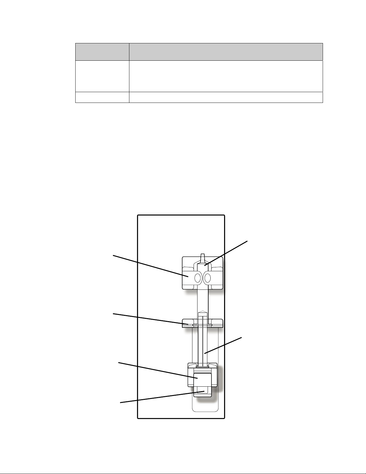
Chapter 1—Overview
Feature Function
Up/Down Keys Increases the speed of the pump when Up arrow () is depressed,
decreases the pump speed when Down arrow () is depressed.
When door is open, simultaneously press the and keys and then
press the or key to select the pump segment diameter.
Tubing Retainer A spring-loaded device that secures the pump segment in place.
The Heparin Pump Module
The heparin pump provides a means of injecting heparin into the blood circuit gradually over
the course of the treatment and/or as a bolus. The pump can accommodate a variety of
syringes that are commercially available. The pump works in conjunction with the “Heparin”
screen where such parameters as the size and type of the syringe, infusion rate, infusion time,
and bolus amount of heparin to be infused are selected.
If heparin is infused manually (by pushing in the carriage lock button while pushing on the
slide carriage), the volume will not be added to the displayed amount, and must be added to
the total heparin amount. Manually moving the carriage to infuse heparin is not
recommended.
Barrel
Lock
Tabs
Wings
Slot
Slide
Carriage
Carriage
Latch
Figure 14 – The Heparin Pump Module (shown with syringe)
Syringe
Syringe
Plunger
2008T Machine Operator’s Manual P/N 490122 Rev U 41

Chapter 1—Overview
The Level Detector Module
The Level detector module is used to monitor the level of fluid in the venous drip chamber.
The venous drip chamber is mounted inside its holder and the blood tubing leading back to
the patient is threaded through the venous line clamp below it. An ultrasonic device inside
the chamber holder monitors the drip chamber for the presence of air. If the level of blood in
the chamber is too low and air is detected, the machine alarms, the blood pumps stops, and
the clamp occludes the venous blood tubing.
An optical sensor located below the occlusion clamp recognizes whether or not blood, an
opaque fluid, is detected in the venous line. When the dialysate supply lines are on the shunt,
and the shunt door is closed, and blood is not sensed, the audible alarm is suppressed entirely.
Also located on the front of the module is a pressure port. The small monitor line from the
drip chamber is connected to the transducer port. The pressure of the venous side of the
blood circuit is read by the transducer mounted on the inside of the module, and the pressure
is displayed in the “Home” screen.
Venous Drip
Chamber
Holder
Level Detector
Sensor
Optical
Detector
Venous
Pressure Port
Up/Down
Level Adjust
Door
Latch
Venous
Clamp
Optical Detector
Door (Rotate
Clockwise to Open)
Figure 15 – The Level Detector Module
42 2008T Machine Operator’s Manual P/N 490122 Rev U

Chapter 1—Overview
Table 7 – Level Detector Features
Feature Function
Venous Pressure
port (P
Venous Drip
Chamber Holder
Level Adjust Keys
Optical Detector
Venous Line
Clamp
Ven.
)
Line from venous drip chamber is connected to a transducer protector
and attached here to provide venous blood pressure readings.
Holds the drip chamber and aligns it with the ultrasonic level detector
sensor. Latching door secures chamber in place.
Raises the level of the fluid in the chamber when the (up arrow)
key is pressed, and lowers the level when the (down arrow) key on
the level detector is pressed.
Secures venous blood tubing leading back to the patient and houses
venous line clamp and optical detector. The optical detector
distinguishes between opaque fluid (blood) and a transparent
medium such as saline.
Automatically occludes the blood tubing leading back to the patient
during blood-alarm situations.
Note: If the machine is in Low Power Mode (display screen is off and the Status Light
flashing green), power to the Level Detector module is turned off. To turn the Level
Detector module back on, simply touch the touchscreen, keyboard, or touchpad. For more
information about Low Power Mode, see page 334 for more information.
Blood Tubing System
The dialysate delivery machine can be used with a variety of blood-tubing configurations.
The modules (Arterial Drip Chamber, Blood Pump, Level Detector, and Heparin Pump) can
be arranged on the 2008T hemodialysis machine in a variety of ways to allow for pre- or
post-arterial pump pressure monitoring. The machine can accommodate most standard blood
tubing that have pump segments ranging from 2 to 10 mm internal diameter. An additional
single needle blood pump and special arterial line with two pump segments and a compliance
chamber is required on a machine set up for single-needle dialysis.
Blood Pressure Module
The Blood Pressure module is located internally with the pressure tubing running from the
back of the machine to the cuff. The module can automatically take the patient’s blood
pressure at defined intervals, record the systolic, diastolic, MAP, and pulse values, and plot
out the results on the “Blood Pressure” screen, “Trends” screen, and optional “Crit-Line”
screen. The pressure cuffs come in a variety of sizes to accommodate low volume through
large adult patients. The Adult size comes standard with the 2008T hemodialysis machine
and can accommodate patients with upper arm circumferences of 25-35 centimeters. An
optional large cuff is also available.
2008T Machine Operator’s Manual P/N 490122 Rev U 43

Chapter 1—Overview
The Dialysate Path
The 2008T hemodialysis machine is a three-stream dialysate delivery machine: it mixes the
dialysate from three different sources and sends it to the dialyzer for treatment. The three
main parts of the dialysate are: purified (RO) water, acid concentrate, and bicarbonate
concentrate. After the machine heats and degasses the water, it mixes in the concentrates to
form dialysate. The machine then filters the dialysate with the DIASAFE
page 273). The ultra-pure dialysate pumps through dialysate lines to the ports on the side of
the dialyzer. Meanwhile, the blood pumps through the bloodlines connected at each end of
the dialyzer. The blood and dialysate meet in the dialyzer but never touch. The dialysate
pulls waste from the patient’s bloodstream and then washes it out the drain. The Balancing
Chamber makes sure that the incoming flow of the dialysate is equal to the volume of the
outgoing flow to control ultrafiltration from the patient’s body. Ultrafiltration (UF) is the
process of removing excess fluid during the treatment. The fluid that is removed is called UF
Removed and the value is displayed on the machine’s “Home” screen.
The Dialysate Section
®
plusUS filter (see
Optional
bibag
Connector
The Dialysate Section contains connectors for acid and bicarbonate concentrates.
Red Acid
Connector
Concentrate Jug
Connector Cap
Extended
Lines Bracket
(optional)
Blue
Bicarbonate
Connector
Fluid
Sample
Port
Figure 16 – The Dialysate Section
Note: The acid and bicarbonate lines can be extended to ten feet in length. Contact Fresenius
Medical Care Spare Parts department or your sales representative for more information.
44 2008T Machine Operator’s Manual P/N 490122 Rev U

Table 8 – Dialysate Section Features
Feature Function
Chapter 1—Overview
Red acid and
blue bicarbonate
connectors
Concentrate Jug
Connector Cap
Extended Lines
Bracket
Fluid Sample Port The Fluid Sample Port allows testing of the UF pump.
bibag
®
System (Optional)
The concentrate connectors draw in acid and bicarbonate
concentrates. The concentrate connectors pull out and connect to
jugs of acid and bicarbonate concentrates or a concentrate central
feed. When connecting, make certain to correctly match red to acid
and blue to bicarbonate concentrates.
The connector cap snaps onto the top of concentrate jugs. The Acid
and Bicarbonate connectors connect to the cap so the machine can
pull concentrate from the jugs.
Optional bracket that is used to coil up extended acid and bicarbonate
lines. The bracket can be mounted in a variety of locations.
The bibag connector is part of the bibag system. It is a hardware option that allows use of a
dry bicarbonate powder to make dialysate solution for the 2008T hemodialysis machine. The
bicarbonate powder is contained in a bag called the bibag disposable. The machine adds
purified (RO) water to the bag and pumps out the liquid bicarbonate concentrate to mix with
the acid concentrate and more RO water.
Note: The “45x” concentrate family must be selected in order to use the bibag system.
When a 45x type concentrate is selected with the bibag module installed, the machine will
automatically detect whether or not a bibag disposable is connected upon entering Dialysis
or SLED.
Note: When using the ‘Independent Cond Test’ Service Mode option (functional software
version 2.72 or later) with the bibag disposable as the bicarbonate source, the 2008T
hemodialysis machine will independently verify the conductivity and pH when running selftests.
Bicarbonate outlet
nozzle
bibag
disposable
handle
Straw
Bicarbonate powder
Figure 17 – The Optional bibag Connector (with bibag disposable)
Door handle
bibag door
(open)
Water inlet
nozzle
bibag disposable
2008T Machine Operator’s Manual P/N 490122 Rev U 45

Chapter 1—Overview
Table 9 – Optional bibag Connector Features
Feature Function
Optional bibag
connector
bibag Door
Bicarbonate Outlet
Nozzle
Water Inlet Nozzle
bibag Disposable
The bibag connector connects the bibag disposable to the machine’s
dialysate path.
The bibag door covers the nozzles of the bibag connector. When the
door is closed with no bag on the bibag connector, the nozzles form a
loop in the dialysate path so the machine can rinse and disinfect the
bibag connector. Pressing down on the bibag door locks the door in
place. Lifting up on the door handle will open the bibag door.
The machine pumps the liquid bicarbonate out of the bibag
disposable through this opening.
The machine adds purified water to the bicarbonate powder in the
bibag disposable through this opening.
The bibag disposable is a bag filled with dry bicarbonate powder. At
the top of the bag are special inlet and outlet ports. These ports
match up with the nozzles on the machine’s bibag connector.
The Bicarbonate Outlet Nozzle connects to a straw inside the bag to
reach the bottom of the bag.
The handle on the bag allows you to easily lift the bibag disposable
off the bibag connector.
See the bibag estimated run time table on page 307 for more
information.
Dialyzer
The 2008T hemodialysis machine is compatible with commercially available dialyzers that
are equipped with standard dialysate connections (ISO 8637). The dialyzer connects to the
dialysate path via the dialysate lines on the shunt interlock.
46 2008T Machine Operator’s Manual P/N 490122 Rev U

The Shunt Interlock
Shunt Door Open
Chapter 1—Overview
Shunt Door Closed
Dialyzer Return
Line Connector
(Red)
Figure 18 – Shunt Interlock, Flow Indicator & Dialyzer Connectors (viewed from back of
machine)
Dialyzer Supply
Line Connector
(Blue)
Shunt
Interlock
Dialysate
Sample Port
Dialysate Flow
Indicator Tube
Float
The shunt interlock is located on the right side of the 2008T hemodialysis machine. It links
the dialysate lines when they are connected to it. The shunt door flips up to reveal colorcoded latching-connectors.
Push the dialyzer connectors onto the shunt interlock to snap them in place
Press down on the end of the red or blue lever and pull out the dialyzer connector to
remove it from the shunt interlock
The dialyzer connectors attach to the dialyzer during dialysis or the shunt interlock during
rinse programs. Make certain to correctly match red to red and blue to blue.
The blue dialyzer supply line features a dialysate flow indicator tube. A moving float in the
tube allows the operator to see when dialysate is running through the lines and the dialyzer.
The float does not move when the machine is in bypass mode. Lifting the shunt door will
manually put the machine in bypass mode.
The dialysate sample port on the same line allows the operator to take a sample of the
dialysate. For more information, see “Testing the Dialysate” on page 347.
2008T Machine Operator’s Manual P/N 490122 Rev U 47

Chapter 1—Overview
IV Pole and Dialyzer Holder
IV Pole Release
Grip
Dialyzer
Holder
Figure 19 – The IV Pole and Dialyzer Holder
Bloodline
Holders
Swivel
Joint
Elbow Release Latch
Button
IV Pole
Clamp
48 2008T Machine Operator’s Manual P/N 490122 Rev U

Table 10 – IV Pole and Dialyzer Holder Features
Feature Function
Chapter 1—Overview
IV Pole
Dialyzer Holder
The IV pole is on the right side of the 2008T hemodialysis machine.
This pole is utilized to hold various medications and solutions that
may be required during a treatment.
The IV pole mount near top half of the machine may feature the
optional PatientCard Reader. For more information, see page 37.
Near the top of the pole is a black release grip that is used to adjust
the height of the IV pole. Lift up on the grip to slide the top of the IV
pole up or down. Let go of the grip to lock the IV pole at its new
height.
The dialyzer holder keeps the dialyzer in place during the treatment.
The end of the dialyzer holder swings shut to clamp around a
dialyzer. It rotates at the swivel joint on an arm. This is so the
dialyzer can be easily flipped in the holder during treatment setup and
end procedures.
The opposite end of the arm clamps on the IV pole when the arm is
straight. To move the arm up or down along the IV pole: slide the
Release Latch Button toward the IV pole and bend the arm upward at
the elbow. The arm’s IV pole clamp will loosen and then the arm can
move freely. To clamp the arm on the IV pole, straighten the arm at
the elbow again.
The dialyzer holder also has bloodline holders like the tubing guides
on the machine’s modules. Press the bloodlines into these holders to
help keep them visible and free from kinks.
Moving the Machine
The 2008T hemodialysis machine has wheels on the bottom to make it easy to move. Before
moving the machine, make sure the IV pole is secured in its lower mount.
The wheel lock may need to be released before the machine will roll. The wheel lock is on
the right side of the 2008T hemodialysis machine at the base. To unlock the wheels, press
down on the front end of the foot pedal. To lock the wheels again, push down on the back
end of the foot pedal.
Unlocked Wheels Locked Wheels
Figure 20 – The Wheel Lock
2008T Machine Operator’s Manual P/N 490122 Rev U 49

Chapter 1—Overview
Warning! Tip Hazard. Do not push or lean against the machine when the wheel lock is set.
Warning! Be careful not to tip the machine when rolling it over uneven surfaces. Push the
machine from the middle when moving it.
Moving across a level surface
Before moving the machine,
properly secure the IV pole
to its lower mount. Hold the
IV pole below its upper
mount as a handle to
maintain control of the
machine. Push the machine
from the middle when
moving it.
Moving over a ¾ inch threshold
Hold IV pole below
upper mount
Secure IV pole to lower
mount
1. Stop machine at
threshold.
Moving down a 1 ½ inch step
1. Stop machine at
step.
Figure 21 – Moving the 2008T Hemodialysis Machine
2. Brace foot against base. Use
IV pole to raise forward
wheels onto threshold. Do
not tip machine too far back!
2. Brace foot against base.
Hold IV pole above upper
mount.
3. Push machine slowly
over threshold. Keep
firm hold on IV pole.
3. Slowly lower machine
down step. Keep firm
hold on IV pole. Do not
tip machine too far
forward!
50 2008T Machine Operator’s Manual P/N 490122 Rev U

Chapter 2
Daily Preparation for Treatment
This chapter provides the qualified operator with the recommended daily procedures for
preparing the 2008T hemodialysis machine for regular hemodialysis operation.
To prepare the 2008T hemodialysis machine for Sustained Low Efficiency Dialysis (SLED),
see Appendix B on page 289.
Covered here are the initial tasks that are to be performed before the patient is connected to
the extracorporeal blood circuit. These tasks are not patient-specific, and are broken down
into three categories:
Setting up the dialysis delivery system
Preparing the extracorporeal blood circuit
Conducting pressure and alarm tests
Starting Point
The following is a checklist of conditions that should exist after installation of the 2008T
hemodialysis machine by a qualified technician. Before beginning the daily preparation
procedures, visually inspect the machine to verify that:
The water supply line is connected to the water inlet and the water is turned on.
The machine’s drain line is inserted into a drain with an air gap.
The power cord is plugged into a grounded, GFI-protected wall socket, and the main
power switch located on the back of the machine is in the ON position.
The heater switch is in the ON position.
The acid/acetate suction line (red connector) is inserted into the red, acid/acetate, rinse
port.
The bicarbonate suction line (blue connector) is inserted into the blue, bicarbonate,
rinse port.
If the machine has the optional bibag connector, check that the bibag door is firmly
closed
The dialyzer supply line (blue connector) and dialyzer return line (red connector) are
inserted into the matching-color connectors of the shunt interlock.
The machine has been recently disinfected and rinsed, and is ready for use.
Ensure the emergency hand crank for the blood pump is available.
If any of the conditions listed vary from those found on the machine, correct them before
continuing with the daily preparation procedure.
2008T Machine Operator’s Manual P/N 490122 Rev U 51

Chapter 2—Daily Preparation for Treatment
Preparing the Dialysis Delivery System
There are two ways to prepare the 2008T hemodialysis machine for a treatment: the standard,
manual setup method or the Auto Start method (functional software version 2.72 or later with
BlueStar
up the machine and begin testing without assistance from the operator, see page 56. To
prepare the 2008T hemodialysis machine using the standard, manual method, see below.
Note: If the display screen is off and the Status Light flashes green, the machine is in Low
Power Mode. To turn the display back on, simply touch the touchscreen, keyboard, or
touchpad. If these are unresponsive, press the Reset key to exit Low Power Mode. For
more information about Low Power Mode, see 334.
TM
Premium). For instructions on using the Auto Start method to automatically set
Note: If the machine is filled with disinfectant or Rinse is the only option that appears in the
“Select Program” screen, the machine must complete a rinse cycle before being used for
treatment. Select Rinse to start the rinse cycle. Upon completion of rinse cycle test the
machine for any residual disinfectant according to the established guidelines of the facility.
Note: During the power up sequence a message is displayed for a few seconds: “Press
Confirm for Service Mode”. If this is done, the machine enters the calibration screens
instead of the “Select Program” screen.
Note: The “Select Program” screen displays any additional software applications (Apps)
that are installed on the 2008T hemodialysis machine (see Figure 22 for an example).
Manual Machine Setup
To manually prepare the 2008T hemodialysis machine for operation:
1. Press the POWER key on the control panel. The “Select Program” screen (see Figure
22) will appear on the monitor after approximately one minute.
Note: If the message “Low Volume Mode Set!” is displayed on the “Select Program”
screen and the current treatment will be for a patient weighing over 40 kg, be sure to set the
‘Low Volume’ option on the “Test & Options” screen to ‘Off’ before inserting the
PatientCard.
2. Flip down the touchpad located below the Control Panel Keypad.
52 2008T Machine Operator’s Manual P/N 490122 Rev U

Chapter 2—Daily Preparation for Treatment
Figure 22 – The Select Program Screen (functional software version 2.72) and Touchpad
Note: If the bibag disposable is the bicarbonate source, do not pull the blue bicarbonate
connector from the machine’s rinse port. Do the following to prepare the bibag disposable:
a) Remove the plastic seal from underneath the water and bicarbonate nozzles of the
bibag disposable.
b) Open the bibag door on the machine by lifting up on the dark-gray handle.
c) With the white bibag handle facing outward, hang the bag on the bibag connector
nozzles.
d) Close the door, making sure it latches firmly in place. An audible click means the
door is closed.
Note: The bibag disposable must hang freely below the bibag connector. Make certain that
there are no jugs or other objects obstructing or touching the bibag disposable.
3. Insert the acid concentrate (red) connector into a centralized acid supply or a jug
containing sufficient acid concentrate for an entire treatment. If acetate concentrate is
being used, insert the red connector into the acetate supply.
Caution: Be sure the jug contains enough concentrate for the entire treatment. If the jug
runs out during treatment, a condition known as “air lock” may occur, causing conductivity
problems.
4. If the machine is being prepared for normal dialysis: select the Dialysis button on the
display screen by highlighting the button with the touchpad and either tapping or pressing
the CONFIRM key. The “Dialysate” screen will appear on the monitor (see Figure 23).
(The optional touchscreen can be used by touching the Dialysis button directly.)
If the machine is being prepared for Sustained Low Efficiency Dialysis (SLED), select
the SLED button instead. For more information on SLED, see Appendix B on page 289.
2008T Machine Operator’s Manual P/N 490122 Rev U 53

Chapter 2—Daily Preparation for Treatment
5. Verify that the concentrate type, displayed near the top of the screen, correctly matches
the prescribed concentrate type, and that the acid/bicarbonate or acetate concentrates
connected to the machine match the type selected. If an incorrect concentrate type is
displayed, the correct concentrate must be entered. To change the concentrate selection,
see “Setting an Acid/Bicarbonate Type” on page 87.
Note: The machine will not allow usage of the bibag disposable unless the 45x concentrate
family is selected in Service Mode.
Current acid
concentrate
selection
Figure 23 – Confirming Concentrates on the Dialysate Screen (functional software version
2.72 or later)
Note: If the machine is set up for use with Citrasate, a ‘Citrate’ meter box will be displayed
in the dialysate constituent list.
6. After the concentrate displayed is correct, verify that the Base Na+ and Bicarbonate are
as prescribed. Press the CONFIRM key, and then select the Home screen-button.
7. If a liquid bicarbonate is to be used for the treatment, insert the bicarbonate concentrate
(blue) connector into a central bicarbonate supply or a jug containing sufficient
bicarbonate concentrate for an entire treatment. Again, be sure the jug contains enough
concentrate for the entire treatment.
Note: If the dry bicarbonate powder in the bibag disposable will instead be the bicarbonate
source, do not pull the blue bicarbonate connector out of your machine’s bicarbonate port.
Doing so will stop the flow to and from the bibag disposable.
Note: Bicarbonate solution is not stable over time. Make a fresh batch for each treatment
according to the manufacturer’s instructions.
54 2008T Machine Operator’s Manual P/N 490122 Rev U

Chapter 2—Daily Preparation for Treatment
Note: Dialysate flow must be ON in order to fill the bibag disposable with heated water.
Note: The bibag disposable contains a fixed volume of bicarbonate powder. Refer to the run
time tables on page 307 to verify that enough run time (including any set-up time and
potential pre-treatment delays) is available to complete a treatment using one bag.
When the machine is ready (water at minimum temperature and no air in the hydraulics), it
will begin mixing the concentrates. During this time, the message “Preparing Dialysate”
will be displayed in the Status Box and the machine will not be ready for testing until this
message clears. Or, if a bibag disposable is connected, the machine will then fill the bag with
heated water to be used as a bicarbonate concentrate for dialysate production. The machine’s
conductivity and temperature readings should stabilize within ten minutes.
While the 2008T hemodialysis machine is preparing the dialysate, the bloodlines may be set
up. Turn to page 59 for instructions on preparing the extracorporeal blood circuit.
2008T Machine Operator’s Manual P/N 490122 Rev U 55

Chapter 2—Daily Preparation for Treatment
Auto Start Machine Setup
The Auto Start method is a program that automatically powers on the 2008T hemodialysis
machine at a scheduled time and, if the concentrates are connected, begins testing the
machine to prepare it for stringing the bloodlines and running the final bloodline tests.
Figure 24 – The Auto Start Program Waiting for Concentrate Connection
To prepare the 2008T hemodialysis machine for Auto Start setup, the following conditions
must also exist for the program to run:
The Auto Start option has been set to run for the current treatment day (see page 338
for information on setting the Auto Start schedule)
The 2008T hemodialysis machine is either off, in Low Power Mode, or displaying the
“Select Program” screen
Note: Auto Start does not cause the machine to exit Low Power Mode. To make
the screen display visible, touch the touchscreen, keyboard, or touchpad.
The ‘Forced Test’ option in Service Mode has been set to ‘No’.
The red acid concentrate connector is inserted into a central acid supply or a jug
containing sufficient acid concentrate for an entire treatment; if the connector is still in
its port, the Auto Start Dialysis button will be green and the Status Box message
“Connect Concentrates” will be displayed as in Figure 24 above. Once the connector is
removed from its port, the machine will wait up to 7 minutes for dialysate conductivity
and temperature to stabilize. If they do not, automatic testing will be cancelled and the
self tests must be run manually.
Note: Both the acid and bicarbonate concentrate supplies must be connected to
stabilize conductivity. Due to the 7-minute time limit, it is recommended to
attach both acid and bicarbonate supplies at the same time. Follow clinic
protocol and procedures.
56 2008T Machine Operator’s Manual P/N 490122 Rev U

Chapter 2—Daily Preparation for Treatment
The bicarbonate source is connected:
If a liquid bicarbonate is to be used: the blue bicarbonate concentrate connector is
either inserted into a central bicarbonate supply or a jug containing sufficient
bicarbonate concentrate for an entire treatment
Or
If the bibag disposable will instead be the bicarbonate source: the bibag
disposable is connected to the bibag connector with the door closed and the blue
bicarbonate concentrate connector is inserted in the blue, bicarbonate, rinse port
Note: If the bibag disposable is the bicarbonate source, do not pull the blue bicarbonate
connector from the machine’s rinse port. Do the following to prepare the bibag disposable:
a) Remove the plastic seal from underneath the water and bicarbonate nozzles of the
bibag disposable.
b) Open the bibag door on the machine by lifting up on the dark-gray handle.
c) With the white bibag handle facing outward, hang the bag on the bibag connector
nozzles.
d) Close the door, making sure it latches firmly in place. An audible click means the
door is closed.
Note: The bibag disposable must hang freely below the bibag connector. Make certain that
there are no jugs or other objects obstructing or touching the bibag disposable.
If any of the conditions listed vary from those found on the machine, correct them before
running the Auto Start program.
When the scheduled Auto Start time occurs, the machine will automatically start the Dialysis
program, confirm the concentrate, and, after the dialysate is prepared, run all of the listed
self-tests except for the Level Detector, Arterial Pressure, Venous Pressure and TMP tests.
At the beginning of the automatic self-test sequence, the Status Box will display the message,
“Auto Start: Testing.” Pressing keys or touching the touchscreen will interrupt the Auto Start
testing.
Figure 25 – Auto Start: Testing
2008T Machine Operator’s Manual P/N 490122 Rev U 57

Chapter 2—Daily Preparation for Treatment
Note: The remaining self-tests will run either when using the Auto Prime feature or by
selecting the Both Tests button after the bloodlines have been placed on the machine. See
the “Test & Options” screen on page 71 for more information.
Note: The Auto Prime option must be set to ‘Yes’ in Service Mode for the Auto Start tests
to occur.
Note: On the “Test & Options” screen, a failure of any of the self-tests is indicated by a red
X in the error box to the right of the test name. The right side of the screen provides
additional information regarding the failure. A description of the test messages can be found
in Chapter 6, “Troubleshooting”.
When the Auto Start self-tests have been successfully completed, the machine will display
the message, “Auto Start: Complete” in the Status Box and the message, “Connect and
prime bloodlines” in the Dialogue Box (see Figure 28). Press the Reset key to clear it and
then follow the instructions on the next page to connect the bloodlines before priming.
58 2008T Machine Operator’s Manual P/N 490122 Rev U

Chapter 2—Daily Preparation for Treatment
Preparing the Extracorporeal Blood Circuit
Use Figure 26 or Figure 27, depending on the configuration of your machine, as a guide for
connecting the bloodlines. The red lines on the machine are guides for arterial bloodline
(from patient to dialyzer). The blue lines on the machine are guides for the venous bloodline
(from the dialyzer to the patient). Be sure to use aseptic technique for all bloodline
connections.
Note: To prepare the 2008T hemodialysis machine for single-needle dialysis, see “Single
Needle Dialysis” in Appendix A.
Note: The Post-pump arterial chamber configuration is incompatible with the Auto Prime
and Assisted Reinfusion options.
Figure 26 – Pre-pump Arterial Chamber Configuration
Figure 27 – Post-pump Arterial Chamber Configuration
2008T Machine Operator’s Manual P/N 490122 Rev U 59

Chapter 2—Daily Preparation for Treatment
Connecting the Extracorporeal Blood Circuit
For the following set of instructions, refer to Figure 13 – The Blood Pump Module on page
40 and Figure 15 – The Level Detector Module on page 42 regarding the names of the
various module parts.
To connect the bloodlines:
Warning! Use aseptic technique.
Note: These are general instructions are for a new, dry-pack dialyzer. Your specific
procedure should be consistent with the dialyzer manufacturer’s instructions.
Arterial Bloodline Setup
1. Close medication port clamp.
2. Snap the arterial chamber into its holder.
3. Connect the arterial monitor line to the arterial pressure port using a transducer protector
and verify that the monitor line is unclamped.
Warning! Transducer protectors should be used between transducers and each pressure
monitor line of the extracorporeal system to prevent the transducers from getting wet. Wet
transducer protectors must be replaced, as they will cause inaccurate pressure readings. If
the external transducer protector and the internal transducer should become contaminated
with blood, the transducer protectors must be replaced, and the transducer must be
disinfected or replaced.
4. Open the blood pump door.
Warning! Inspect the blood pump rotor for proper operation (tubing guide posts not bent,
rollers move freely, crank lever moves freely). Bent or loose tubing guide posts can damage
bloodlines. Replace rotor if necessary. See page 182 for rotor diagram.
5. If necessary, set the pump for the diameter of the blood pump segment:
Press the Up () and Down () keys on the blood pump module simultaneously.
The display will flash.
Press the Up () or Down () key on the blood pump module until the diameter of
the pump segment being used is displayed.
6. Load the blood pump segment:
a. Press and hold the Start/Stop key on the blood pump module to align rotor for line
insertion.
b. Grasp the pump segment and, using thumb pressure, position it behind the left yoke
by pressing the tubing retainer inward. Be sure the end of the segment clears the
bottom of the yoke.
Warning! Make sure the collar of the pump segment is positioned below the bottom of the
yoke. This will minimize the possibility of the segment kinking during pump operation.
Warning! Keep fingers free of rotor while it is turning to avoid possible injury.
c. Press and hold the Start/Stop key. The rotor will rotate to the 5 o’clock position and
stop. Relieve pressure on the retainer and release the segment. The beginning of the
pump segment should be secured between the left yoke and the tubing retainer.
60 2008T Machine Operator’s Manual P/N 490122 Rev U

Chapter 2—Daily Preparation for Treatment
d. Press and hold the Start/Stop key again and the rotor will rotate one full turn to
automatically position the remainder of the segment within the pump housing. After
loading, any extra pump segment tubing length should be on the right side of the
pump.
e. Release the Start/Stop key when the pump segment has been inserted along the track
inside the pump housing all the way to the right yoke.
f. Grasp the remaining portion of the segment and, using thumb pressure in a manner
similar to step b, position it behind the right yoke.
g. Release the tubing retainer and close the pump door. Be sure the pump segment is
free of kinks and both ends of the segment extend below the yoke.
7. Snap remaining arterial tubing in the clips along the red guidelines shown on modules.
8. Aseptically place the patient end of the arterial line into the priming bucket clip. Snap
the dialyzer end of the arterial bloodline into the dialyzer holder clip.
Warning! Do not allow the ends to touch the fluid in the bucket to prevent contamination.
Venous Bloodline Setup
1. Close medication port clamp.
2. Open the level detector door and roll the venous drip chamber into its holder with the
filter below the sensor heads and the line on the chamber above the door. Close and latch
the door.
Warning! The level detector must be calibrated to the venous line model being used.
Warning! If the venous chamber contains a filter, be sure the filter portion of the chamber is
positioned below the ultrasonic sensor heads of the drip chamber holder.
3. Connect the venous pressure monitor line to the pressure port. Be sure to insert a
transducer protector between the line and the port. Verify that the monitor line is
unclamped.
Warning! Transducer protectors should be used between transducers and each pressure
monitor line of the extracorporeal system to prevent the transducers from getting wet. Wet
transducer protectors must be replaced, as they will cause inaccurate pressure readings. If
the external transducer protector and the internal transducer should become contaminated
with blood, the transducer protectors must be replaced, and the transducer must be
disinfected or replaced.
4. Snap remaining venous tubing in the clips along the blue guidelines shown on modules
(do not insert the venous bloodline into the venous clamp yet).
5. Snap the dialyzer end of the venous bloodline into the dialyzer holder clip.
6. Aseptically place the patient end of the venous line into the priming bucket clip.
Warning! Do not allow the ends to touch the fluid in the bucket to prevent contamination.
Dialyzer Setup
1. Mount the dialyzer in its holder, arterial-end up.
2. If the CLiC device will be used for this treatment, connect the Crit-Line Blood Chamber
to the dialyzer’s arterial port at this time. For more information, see the 2008T
Hemodialysis Machine with CLiC User’s Guide (P/N 490206).
2008T Machine Operator’s Manual P/N 490122 Rev U 61

Chapter 2—Daily Preparation for Treatment
Priming the Blood Circuit
There are three different ways to prime the bloodlines on the 2008T hemodialysis machine:
Standard Prime, Prime Amount, and Auto Prime (functional software version 2.72 with
BlueStar Premium).
The Standard Prime method allows the operator to prime the blood circuit by
controlling the flow of the saline manually. Continue below to use the Standard
Prime method.
The Prime Amount method is a machine option that is set in the Service Mode, and
limits the amount of saline used in the priming procedure to a preset volume. Turn to
page 63 to use the Prime Amount method.
The Auto Prime method aids the operator in automatically priming the bloodlines and
running the bloodline self-tests. This method can be used after the machine has been
automatically started using the Auto Start program (see page 56) but can also be used
after the Auto Start portion of the self-tests have passed for subsequent treatments.
Turn to page 65 to use the Auto Prime method.
Prime the blood circuit according to how your machine was set up. Follow your unit protocol
or dialyzer manufacturer’s instructions for priming and rinsing dialyzers.
Warning! Use aseptic technique.
Standard Prime Method
1. Connect the dialyzer end of the arterial bloodline to the arterial port of the dialyzer.
Rotate the dialyzer to the arterial end down position.
2. Connect the dialyzer end of the venous bloodline to the venous port of the dialyzer.
3. Insert the venous line in the venous line clamp and the optical detector. Close the optical
detector door.
Warning! The tubing beneath the venous drip chamber must be inserted into the venous line
clamp and the optical detector.
4. Hang a saline bag and attach an administration line, if not already attached, to the saline
port on the arterial bloodline. Aseptically spike the saline bag.
5. Gravity prime the patient end of the arterial bloodline below the saline “T” with saline.
When primed, clamp the patient end of the arterial bloodline.
6. If the heparin pump is to be used: connect the heparin syringe, prime the heparin line
with heparin, and load heparin syringe into heparin pump. If the heparin pump is not
used, clamp the heparin line.
62 2008T Machine Operator’s Manual P/N 490122 Rev U

Chapter 2—Daily Preparation for Treatment
7. On the control panel keypad, press the Prime key.
8. Press the blood pump Start/Stop key and run the blood pump at a rate of 150 ml/min.
Adjust the flow rate by pressing the (up) or (down) keys.
9. Fill the arterial drip chamber to an acceptable level using the key (level adjust) on the
blood pump. Close the arterial pressure monitor line clamp and disconnect the line from
the arterial pressure port so the port is open to atmosphere.
Warning! The Level Adjust key on the Blood Pump module can only be used to raise the
level in the arterial chamber. Do not press the Level Adjust key so long that the pressure
transducer protector becomes wet. Wet transducer protectors must be replaced to avoid
erroneous pressure readings.
10. Run the blood pump to flush saline through the circuit until a fluid level is detected in the
venous drip chamber. The blood pump will stop when the level detector senses a level of
fluid or two minutes have elapsed, whichever comes first.
11. Press the Reset key on the control panel to restart the blood pump and continue flushing
saline through the blood circuit in accordance with established facility protocol regarding
dialyzer rinsing.
12. After the required saline amount has passed through the circuit, press the Start/Stop key
on the blood pump to stop the pump.
13. Clamp the patient end of the venous bloodline.
14. Adjust the fluid levels in the drip chambers by pressing the appropriate or level
adjust keys. Close the venous pressure monitor line clamp and disconnect the monitor
line from the venous pressure port so the port is open to atmosphere.
15. Aseptically connect the patient end of the arterial bloodline to the patient end of the
venous bloodline using a sterile recirculation piece. Unclamp both lines.
16. Set the blood pump rate to 350-400 ml/min. Press the blood pump Start/Stop key to
start the pump and begin recirculation. If necessary, press the Reset key to clear any
alarms.
17. Ensure that the extracorporeal circuit is free of air bubbles.
Next, turn to page 71 to run the self-tests and finish connecting the bloodlines.
Prime Amount Method
1. Connect the dialyzer end of the arterial bloodline to the arterial port of the dialyzer.
Rotate the dialyzer to the arterial end down position.
2. Connect the dialyzer end of the venous bloodline to the venous port of the dialyzer.
3. Hang a saline bag and attach an administration line, if not already attached, to the saline
port on the arterial bloodline. Aseptically spike the saline bag.
2008T Machine Operator’s Manual P/N 490122 Rev U 63

Chapter 2—Daily Preparation for Treatment
4. Gravity prime the patient end of the arterial bloodline below the saline “T” with saline.
When primed, clamp off the patient end of the arterial bloodline.
5. If the heparin pump is to be used: connect the heparin syringe, prime the heparin line
with heparin, and load heparin syringe into heparin pump. If the heparin pump is not
used, clamp the heparin line.
6. On the control panel keypad, press the Prime key.
7. Press the blood pump Start/Stop key and run the blood pump at a rate of 150 ml/min.
Adjust the flow rate by pressing the (up) or (down) keys.
8. Fill the arterial drip chamber to an acceptable level using the key (level adjust) key on
the blood pump. Close the arterial pressure monitor line clamp and disconnect the line
from the arterial pressure port so the port is open to atmosphere.
Warning! The Level Adjust key on the Blood Pump module can only be used to raise the
level in the arterial chamber. Do not press the Level Adjust key so long that the pressure
transducer protector becomes wet. Wet transducer protectors must be replaced to avoid
erroneous pressure readings.
9. The blood pump will start and continue to run until the pre-set amount of saline has been
flushed through the circuit. When blood pump stops, clamp the patient end of the venous
bloodline.
10. Insert the venous bloodline into the venous line clamp and optical detector on the level
detector module. Close the optical detector door.
Warning! The tubing beneath the venous drip chamber must be inserted into the venous line
clamp and the optical detector.
11. Adjust the fluid levels in the drip chambers by pressing the appropriate level adjust keys.
Close the venous pressure monitor line clamp and disconnect the monitor line from the
venous pressure port so the port is open to atmosphere.
12. Aseptically connect the patient end of the arterial bloodline to the patient end of the
venous bloodline using a sterile recirculation piece. Unclamp both lines.
13. Set the blood pump rate to 350-400 ml/min. Press the blood pump Start/Stop key to start
the pump and begin recirculation. If necessary, press the Reset key to clear any alarms.
14. Ensure that the extracorporeal circuit is free of air bubbles.
Next, turn to page 71 to run the self-tests and finish connecting the bloodlines.
64 2008T Machine Operator’s Manual P/N 490122 Rev U

Chapter 2—Daily Preparation for Treatment
Auto Prime Method with Auto Start Self-Tests Already Run
Figure 28 – Auto Prime Button on the Test & Options Screen with Auto Start program
If the ‘Auto Prime’ option is set in Service Mode, the Auto Prime button is displayed on the
“Test & Options” screen. This button is available when the Tx Clock is paused and no blood
is sensed and is used to aid the operator in automatically priming the bloodlines after the
Auto Start portion of the self-tests have been run (with the exception of the Level Detector,
Arterial, Venous, and TMP self-tests). If the Independent Conductivity test is shown at the
end of the test list, the conductivity has also been independently verified by the machine and
the independent conductivity reading is displayed on the “Dialysate” screen under the
heading “Pre Tx conductivity” (see Table 11 on page 82 for more information). If a bibag
disposable is the bicarbonate source, the conductivity and approximate pH have already been
independently verified by the Independent Conductivity/pH test.
To begin priming the bloodlines using the Auto Prime method, select the Auto Prime button,
listen for the beep, and continue on to the next page.
Warning! After selecting and confirming the Auto Prime button, the machine will beep.
As a test of the audible alarm system, make certain that the sound occurs. If the machine
fails this or any of the Pressure, Alarm, and Diasafe tests and the cause cannot be corrected,
or if it fails subsequent tests, it should not be used for treatment. Remove the machine from
service and have it inspected by a qualified technician to correct the problem.
Note: This feature completes the remainder of the automatic testing performed during the
Auto Start program. If the Auto Start program’s self-tests were not run, both the Alarm and
Pressure tests must be run before using Auto Prime; turn to page 71 to first run the self-tests.
Note: The Auto Prime feature is disabled when the ‘Single Needle’ option is set.
2008T Machine Operator’s Manual P/N 490122 Rev U 65

Chapter 2—Daily Preparation for Treatment
Note: This procedure is shown using CombiSet bloodlines (P/N 03-2722-9) and a new, drypack dialyzer; if a different bloodline set is used, the clinic is responsible for providing
instructions.
Note: If the dialyzer requires more saline than is programmed as the default ‘Prime
Amount’ in Service Mode, follow clinic protocol to resolve the issue.
Figure 29 – First Auto Prime Screen
After selecting the Auto Prime button, the first “Auto Prime” screen is displayed (see
above). Follow the on-screen instructions to prime the bloodlines before treatment:
Note: Pressing the Escape key will cancel priming and exit the “Auto Prime” screens and
display the “Test & Options” screen.
1. Attach bloodlines with ends in prime bucket
Follow the on-screen diagram to snap the drip chambers into their holders and
aseptically place the patient ends of the bloodlines into the priming bucket clip. Make
sure the line on the venous drip chamber is positioned above the Level Detector door
to prevent the transducer protectors from getting wet. Snap the dialyzer ends of the
bloodlines into the bloodline holders on the dialyzer holder.
Warning! Do not allow the ends to touch the fluid in the bucket to prevent contamination.
66 2008T Machine Operator’s Manual P/N 490122 Rev U

Chapter 2—Daily Preparation for Treatment
2. Put line in venous clamp and close med ports
Ensure the venous bloodline is inserted into the venous line clamp below the optical
detector. Close the clamps on the medication ports on each of the drip chambers.
Warning! The tubing beneath the venous drip chamber must be inserted into the venous line
clamp and the optical detector.
3. Connect arterial and venous pressure monitor lines, leave unclamped
The arterial and venous pressure monitor lines must be unclamped and connected to
their pressure ports.
4. Connect bloodlines to dialyzer, arterial end up
Connect the arterial and venous bloodlines to the dialyzer with the red, arterial
bloodline at the top of the dialyzer.
5. Connect dialysate lines to dialyzer
With the bloodlines already connected as shown in the on-screen diagram, connect
the dialysate lines to the dialyzer. Pull on the dialyzer connectors to make sure they
are firmly connected to the dialyzer and close the shunt door afterward.
Note: All dialyzer connectors must be fastened tightly to prevent air from entering the
dialysate circuit or to prevent dialysate from leaking from the dialyzer.
6. Open saline clamps and gravity prime arterial line to prime bucket
Open the saline port clamp on the arterial bloodline then gravity prime the patient
end of the arterial bloodline below the saline “T” with saline.
7. Close clamps , raise level in art. chamber
When the arterial bloodline below the saline “T” is primed with saline, close the
clamp at the patient end of the arterial blood and close the heparin line clamp. Use
the key (level adjust) on the blood pump to set the arterial drip chamber to an
acceptable level if necessary.
8. Press Start button to prime
Press the Start button to automatically start the blood pump and run saline through
the bloodlines. The Start button will be grayed-out during priming. When the Prime
Progress bar graph reaches 100%, the next set of instructions will be displayed to
recirculate the saline, see the next page.
2008T Machine Operator’s Manual P/N 490122 Rev U 67

Chapter 2—Daily Preparation for Treatment
Figure 30 – Second Auto Prime Screen: Recirculate Saline
Follow the on-screen instructions to recirculate saline in the bloodlines before treatment:
9. Connect arterial and venous bloodlines with sterile recirc piece
Aseptically connect the patient end of the arterial bloodline to the patient end of the
venous bloodline using a sterile recirculation piece as shown in the diagram.
10. Open arterial clamp
Open the clamp at the patient end of the arterial bloodline.
11. Rotate dialyzer
Rotate the dialyzer to venous end up to clear the remaining air out of the dialyzer.
The Auto Prime method requires the dialyzer to be flipped only once during setup
and the treatment can be run with the dialyzer venous end up if desired.
12. Press Start button to Recirc Saline
Press the Start button to start the blood pump and recirculate the saline. The
bloodline test will begin, followed by the saline recirculation program. A bar graph
will fill to show the progress of the test and recirculation program. The Start button
will be grayed-out as the test runs.
Note: The recirculation time depends on the Recirc Goal and Recirc Time settings in
Service Mode.
When the Test & Recirc bar graph shows 100%, the machine will display the
message, “Auto Prime Complete, Press Confirm” in the Dialogue Box. Press the
CONFIRM key to exit this screen and view the “Test & Options” screen (see next
page).
68 2008T Machine Operator’s Manual P/N 490122 Rev U

Chapter 2—Daily Preparation for Treatment
Figure 31 – Test & Options Screen with Independent Conductivity/pH and all tests complete
The “Test & Options” screen will display all the completed tests. The message “Test
Complete” will be displayed in the Status Box. Press the RESET key to clear the message.
For more information on reviewing test results on the “Test & Options” screen, see page 72.
Note: If the Pressure and Alarm tests have not been successfully completed, select the Both
Tests button to run the remaining tests.
Continue on the next page to perform the final setup of the machine before entering the
treatment parameters.
2008T Machine Operator’s Manual P/N 490122 Rev U 69

Chapter 2—Daily Preparation for Treatment
Final Setup when using Auto Prime Method
At this point, all self-tests should have been successfully completed and the saline should be
recirculating in the bloodlines. If the ‘Independent Conductivity’ test (functional software
version 2.72 or later with BlueStar Premium) was run as part of the self-tests and a bibag
disposable is the bicarbonate source, the conductivity and approximate pH have already been
independently verified by the Independent Conductivity/pH test.
If the Independent Conductivity self-test was successfully completed but a bibag
disposable is not the bicarbonate source, check the dialysate’s pH level.
If the Independent Conductivity self-test is not listed in the self-tests on the “Test &
Options” screen, check the dialysate’s conductivity and pH level.
Warning! Always verify the conductivity and approximate pH of the dialysate solution
through independent means before initiating each dialysis treatment. Independent means
could be by using an external conductivity meter, pH meter, pH paper or by using the
machine’s independent conductivity test. An approximate pH check is also part of the
machine’s independent conductivty test when a bibag disposable is connected. Verify that
the conductivity is within 0.4 mS/cm of the theoretical conductivity value (TCD) and the pH
is between 6.9 and 7.6 if using a pH meter or pH paper. If conductivity and pH are not
within these limits, do not initiate dialysis. The machine’s independent conductivity test
relies on the use of prequalified manufactured acid concentrates or verified batch
concentrates; the pH check relies on the use of these concentrates and the bibag. It is the
responsibility of the user to ensure that non-prequalified manufactured acid concentrates
have the correct pH. For more information on collecting a dialysate sample for external
testing, see “Testing the Dialysate” on page 347.
Continue below with the final setup steps:
1. Check blood tubing to ensure that there are no kinks, especially between the blood pump
and the dialyzer.
Warning! Check all bloodlines for kinking. Improper blood flow may cause hemolysis of
the blood.
2. Replace the saline bag with a fresh bag if necessary.
3. Check for a normal dialysate flow by observing the rise and fall of the external flow
indicator located on the dialyzer supply line. The float should drop four times in about
15 seconds for a 500 ml/min flow, or four times in 10 seconds for an 800-ml/min flow.
4. Open the shunt door and verify that the machine goes into bypass mode. In bypass mode,
the float in the flow indicator of the dialyzer supply line should drop and remain at the
bottom of the indicator and an audible alarm may sound.
Note: The 2008T hemodialysis machine can be configured (in Service Mode) so that audible
alarms occur only when the optical detector senses blood. If this option is not selected, an
audible alarm will sound when the shunt interlock door is open.
Next, turn to page 76 to enter the treatment parameters and prepare to connect the patient to
the machine for treatment.
70 2008T Machine Operator’s Manual P/N 490122 Rev U

Chapter 2—Daily Preparation for Treatment
Testing the 2008T Hemodialysis Machine
Before beginning treatment, the 2008T hemodialysis machine should undergo Pressure and
Alarm tests to ensure that it is functioning properly. There are four different ways to run selftests for the machine:
If the machine has been automatically started up using the Auto Start program and the
Auto Prime program (functional software version 2.72 or later with BlueStar Premium)
has been completed, then all testing has already been automatically run; turn to page 76
to enter the treatment parameters and prepare to connect the patient to the machine for
treatment.
If the bloodlines have not been primed yet, the majority of self-tests can be run before
selecting the Auto Prime program (during which the remaining four self-tests will be
completed). Select the Both Tests button in the “Test & Options” screen to run the Auto
Start self-tests before priming then turn to page 65 to run the Auto Prime program.
If the Auto Start program has been run but Auto Prime is not desired, then four alarm
self-tests remain: the Level Detector, Arterial Pressure, Venous Pressure, and TMP selftests (see below). Select either the Both Tests or the Alarm Test button to complete the
remaining self-tests. Turn to page 74 to perform the final setup procedure.
If the machine has not been automatically started up using the Auto Start program and the
bloodlines have already been primed, all pressure and alarm tests must be run at this time.
Select the Both Tests button in the “Test & Options” screen to start the test, see below:
Note: The 2008T hemodialysis machine can be configured so that this testing is mandatory
after power up with the Service Mode ‘Forced Test’ option selected (see page 309 for more
information). In this case, the test will start on its own shortly after the operator powers the
machine on.
Note: The ‘Forced Test’ option must be set to ‘No’ when using the Auto Start feature.
To run the test sequence using the Both Tests, Alarm Test, or Pressure Test button,
The dialyzer lines must be connected to the shunt with the interlock door closed.
The machine must be in an alarm-free condition by allowing sufficient time for the
dialysate to reach proper conductivity and temperature. This takes about five minutes
from the time the concentrate is confirmed on the “Dialysate” screen (see Figure 23 on
page 54).
Arterial and venous monitor lines must be clamped and removed from the pressure
monitor ports so the monitor ports are open to atmosphere.
UF and SVS must be off.
Warning! It is essential that the 2008T hemodialysis machine’s balancing system is
operating properly. The machine must successfully complete a Pressure test before each
treatment, especially when using high-flux dialyzers.
Note: If the Service Mode ‘Independent Cond Test’ option is enabled (functional software
version 2.72 or later), the Independent Conductivity self-test will be listed among the selftests. Running this test will independently verify the conductivity of the dialysate. If the
bibag disposable is the bicarbonate source for the treatment, the Independent
Conductivity/pH self-test will be listed and the machine will independently verify both the
conductivity and pH of the dialysate. See page 316 for more information.
2008T Machine Operator’s Manual P/N 490122 Rev U 71

Chapter 2—Daily Preparation for Treatment
To run the Pressure and Alarm tests:
1) From any
screen, select
Test & Options
2) From the
“Test & Options”
screen, select
Both Tests
3) Press
CONFIRM
Figure 32 – Starting Automatic Tests (functional software version 2.72 or later with lines on
shunt)
Test Sequence
The automated test sequence consists of two distinct parts—Alarm tests and Pressure Holding
tests. The Pressure Holding Test, the Alarm test, or both tests can be started by selecting the
corresponding button on the “Test & Options” screen and pressing the CONFIRM key on
the touchpad. After a long power down, however, only the Both Tests button is enabled.
72 2008T Machine Operator’s Manual P/N 490122 Rev U

Chapter 2—Daily Preparation for Treatment
Individual tests are identified as shown on the “Test & Options” screen. A failure of any of
the tests is indicated by a red X in the error box to the right of the test name.
The Alarm test consists of tests that verify the integrity of the settable alarm limits of the
system. Both the alarm and pressure tests should be conducted by the operator prior to each
treatment.
The Pressure Holding Test (PHT) consists of two separate tests that are conducted
sequentially. The purpose of the PHT test is to ensure the pressure integrity of the hydraulic
system under actual pressures generated during the normal operation of the system. PHT
must be performed before each high-flux treatment.
If all tests are completed successfully, a message “Test Complete” appears in the Status
Box. The operator must press Reset once to clear the message. Patient-specific treatment
parameters (other than UF related) can be entered at any time during the test.
An audible alarm sounds only if a test has failed. In a failure situation, after all of the tests
have been completed, the message “Test Failed,” “Alarm Test Failed,” or “Pressure Test
Failed” is displayed in the Status Box depending on the nature of the failure. A red X
appears in the Error box designating the test(s) failed. The right side of the screen provides
additional information regarding the failure. A description of the test messages can be found
in Chapter 6, “Troubleshooting”. Pressing the Reset key once mutes an alarm; pressing it a
second time resets the right side of the screen.
Figure 33 – Test Failure Screen (showing functional software version 2.72 or later with
BlueStar Premium)
Warning! After selecting and confirming a test button, the machine will beep. As a test of
the audible alarm system, make certain that the sound occurs. If the machine fails this or
any of the Pressure, Alarm, and Diasafe tests and the cause cannot be corrected, or if it fails
subsequent tests, it should not be used for treatment. Remove the machine from service and
have it inspected by a qualified technician to correct the problem.
2008T Machine Operator’s Manual P/N 490122 Rev U 73

Chapter 2—Daily Preparation for Treatment
The 2008T hemodialysis machine can be set up to perform online PHTs during treatment.
These tests routinely happen every 12 minutes, and check the integrity of the hydraulic
system. In the event of a failure, an alarm sounds and a message is displayed in the Status
Box. For more information see “Online Pressure Holding Test” on page 163.
Recirculation and Final Set-Up Procedure
If the Auto Prime program (functional software version 2.72 or later with BlueStar Premium)
has been successfully completed, then all setup and testing is complete. Turn to page 76 to
enter the treatment parameters and prepare to connect the patient to the machine for
treatment.
If the 2008T hemodialysis machine has been set-up using the Standard Prime or Prime
Amount methods, the following steps must still be performed:
1. Rotate dialyzer to arterial inlet up.
2. Check the conductivity and pH of the dialysate. If the optional ‘Independent
Conductivity Test’ (see page 71 for more information) is enabled, the dialysate
conductivity has already been independently verified and the reading is displayed on the
“Dialysate” screen. If a bibag disposable is the bicarbonate source for the treatment, the
pH has also been independently confirmed as a result of this test. If using a reuse
dialyzer, test for residual disinfectant before connecting the dialysate lines to the dialyzer.
For more information on collecting a dialysate sample for external testing, see “Testing
the Dialysate” on page 347.
Warning! Always verify the conductivity and approximate pH of the dialysate solution
through independent means before initiating each dialysis treatment. Independent means
could be by using an external conductivity meter, pH meter, pH paper or by using the
machine’s independent conductivity test. An approximate pH check is also part of the
machine’s independent conductivty test when a bibag disposable is connected. Verify that
the conductivity within 0.4 mS/cm of the theoretical conductivity value (TCD) and the pH is
between 6.9 and 7.6 if using a pH meter or pH paper. If conductivity and pH are not within
these limits, do not initiate dialysis. The machine’s independent conductivity test relies on
the use of prequalified manufactured acid concentrates or verified batch concentrates; the
pH check relies on the use of these concentrates and the bibag. It is the responsibility of the
user to ensure that non-prequalified manufactured acid concentrates have the correct pH.
For more information on collecting a dialysate sample for external testing, see “Testing the
Dialysate” on page 347.
Note: If 1.5x or 2x dialysate flow (Auto Flow) is selected, be sure that the dialysate flow
rate is at least the minimum required rate (depending on facility procedure and
manufacturer’s instructions).
3. Connect dialysate lines to dialyzer by matching the color of the dialyzer connector to the
color of the blood tube fitting and then close the shunt door. When done correctly, the
red arterial blood tubing connector and the red dialyzer connector of the dialysate line
should be connected to the corresponding ports at the top of the dialyzer. This is to create
a counter-current flow (blood flowing from top to bottom, dialysate flowing from bottom
to top) inside the dialyzer to maximize clearance.
4. Pull on the dialyzer connectors to make sure they are firmly connected to the dialyzer.
74 2008T Machine Operator’s Manual P/N 490122 Rev U

Chapter 2—Daily Preparation for Treatment
Note: All dialyzer connectors must be fastened tightly to prevent air from entering the
dialysate circuit or to prevent dialysate from leaking from the dialyzer.
5. Reconnect arterial and venous monitor lines to their respective ports. Unclamp the lines.
6. When the dialysate compartment is filled, rotate the dialyzer so the arterial inlet is down.
7. After priming the extracorporeal blood circuit, press Reset to clear all alarms. Set the
blood pump rate to 350-400 ml/min and start the blood pump to begin recirculating the
saline through the circuit.
8. Press the (down) key on the Level Detector module to lower the fluid level in the drip
chamber. Verify that the blood pump stops and the venous clamp occludes.
Warning! The test of the level detector system must be run as a precaution and aid to
identifying potential failures. Remove the machine from service if it fails this test.
9. Press the (up) key on the Level Detector module to raise the fluid level in the drip
chamber to an acceptable level.
10. Check blood tubing to ensure that there are no kinks, especially between the blood pump
and the dialyzer.
Warning! Check all bloodlines for kinking. Improper blood flow may cause hemolysis of
the blood.
Warning! If using a dialyzer that has been stored in a liquid disinfectant such as
formaldehyde, test the recirculating saline solution for residual disinfectant according to
established facility protocol or the manufacturer’s instructions. Special rinsing techniques
must also be employed to assure the concentration of disinfectant is reduced and maintained
at an appropriate level. These rinsing procedures are the responsibility of the medical
director. The procedure must include a test for residual disinfectant and techniques to avoid
rebound of the disinfectant. Turning the dialysate flow off when using a reused dialyzer
may allow the chemical disinfectant to rebound (increase) to an unacceptable level.
11. Replace saline bag with a fresh bag if necessary.
12. Check for a normal dialysate flow by observing the rise and fall of the external flow
indicator located on the dialyzer supply line. The float should drop four times in about
15 seconds for a 500 ml/min flow, or four times in 10 seconds for an 800-ml/min flow.
13. Open the shunt door and verify that the machine goes into bypass mode. In bypass mode,
the float in the flow indicator of the dialyzer supply line should drop and remain at the
bottom of the indicator and an audible alarm may sound.
Note: The 2008T hemodialysis machine can be configured (in Service Mode) so that audible
alarms occur only when the optical detector senses blood. If this option is not selected, an
audible alarm will sound when the shunt interlock door is open.
Next, turn to page 76 to enter the treatment parameters and connect the patient to the machine
for treatment.
2008T Machine Operator’s Manual P/N 490122 Rev U 75

Chapter 3
Setting Treatment Parameters
This chapter instructs the patient care specialist on the procedures for entering
patient-specific treatment parameters. The procedures for preparing the machine for daily
use, in Chapter 2, must be completed prior to setting treatment parameters.
Before proceeding, be sure that:
The machine has passed the alarm and pressure tests.
The dialysate is at the proper temperature, conductivity, and pH.
The dialysate has been tested and found free of residual disinfectant.
The treatment parameters can be entered in a variety of ways: screen-by-screen entry (see
page 77), using the “Default Parameters” screen, or using the PatientCard to automatically
download them to the 2008T hemodialysis machine.
The “Default Parameters” screen is available by pressing and confirming the New Tx key
when the Service Mode ‘Default Rx Screen’ option is set to ‘Yes’ (functional software
version 2.72 or later), see page 118 to continue.
To use the PatientCard and “Prescription” screen (using functional software version 2.72
or later), turn to page 125 to continue.
Warning! Do not connect a patient to the machine or attempt to set treatment parameters
until these conditions have been met.
Warning! The values shown in pictures here are for example only. Parameters must be
entered as prescribed by the patient’s physician. Failure to enter correct parameters could
result in serious injury or death.
76 2008T Machine Operator’s Manual P/N 490122 Rev U

Chapter 3—Setting Treatment Parameters
Recommended Order for Screen-by-Screen Entry
The process of setting patient-specific treatment parameters screen-by-screen should be done
in a specific order. The table below lists the order the screens should be opened, and
parameter to set in each of them.
Dialysate Screen—Access the Sodium and Bicarbonate level of the dialysate and
display the constituent concentration as prescribed by the physician.
Home Screen—Access the UF and Sodium Variation System (SVS) parameters,
dialysate flow, dialysate temperature, display conductivity, and later, start the treatment.
Test & Options Screen—Settings to perform single-needle or Low Volume dialysis or
use high-flux dialyzers are activated in this screen. The patient ID (if applicable) is also
entered here.
Heparin Screen—Set the parameters for administering heparin.
Kt/V AF Screen—Set the parameters for the Kt/V display and run the Access Flow
measurement.
BTM/BVM Screen or Crit-Line Screen—If applicable, set the BTM and BVM or
Crit-Line
Blood Pressure Screen—Set pressure and interval settings to facilitate taking pulse
and blood pressure readings automatically.
Before entering treatment parameters, the existing parameters and settings should be reverted
to their defaults. This is done using the New Tx key, continue to the next page.
®
parameters.
2008T Machine Operator’s Manual P/N 490122 Rev U 77

Chapter 3—Setting Treatment Parameters
New Treatment Key
When the 2008T hemodialysis machine is first turned on in preparation for daily operation
(after a long power down), all treatment parameters revert to their default settings. This can
also be accomplished by pressing the New Tx (New Treatment) key when in Dialysis/SLED.
The New Tx key allows the operator to reset patient treatment parameters to their default
settings without interrupting the power to the machine. If the PatientCard is not used, the
New Tx key should be used to prepare the 2008T hemodialysis machine for each treatment.
After pressing and confirming the New Tx key or after a long power down:
All treatment data (blood pressure, Kt/V, Patient ID) are deleted. The treatment
summary information is moved to the previous record in the “Trends” screen.
Crit-Line/BVM settings are reset to default values
The RTD counter is reset to zero
All heparin treatment parameters are reset to zero
SVS profile is reset to None
UF treatment parameters are reset as follows:
o UF profile is reset to None
o UF Removed is reset to zero
o UF Goal = 3000
o UF Time = 3:00
o UF Rate = 1000
The “Dialysate” screen is displayed and the concentrate will need to be confirmed
Note: If the Service Mode ‘New Tx Rx Warning’ (New Treatment Prescription Warning)
option is enabled (
the New Tx key will display pop-up windows if the Base Na+ and Bicarbonate values do
functional software version 2.72 or later), resetting the treatment using
not match the nominal concentrate settings. The operator must then confirm the values are
not nominal. See page 322 for more information. This option is disabled when using the
PatientCard.
When the Service Mode ‘Default Rx Screen’ option is set to ‘Yes’ (functional software
version 2.72 or later), pressing and confirming the New Tx key will display the “Default
Parameters” screen where the operator may conveniently access most treatment parameters in
one place, see page 118 for more information.
To activate the New Treatment Option:
Figure 34 – New Tx key
1) Press the New Tx key.
Note: When pressing the New Tx key,
the cursor will disappear because a new
parameter is being entered.
2) Press CONFIRM or
press Escape to cancel.
Note: Pressing CONFIRM
or Escape will cause the
cursor to reappear.
78 2008T Machine Operator’s Manual P/N 490122 Rev U

Entering a Treatment Parameter
Treatment parameters can be entered quickly and easily using the keyboard, touchpad, and
touchscreen. All editable treatment data are displayed in yellow rectangular buttons in the
treatment screens (for a description of the different types of buttons, see page 31). To change
a treatment parameter in any screen, highlight the parameter to change by selecting the
corresponding button on the display screen. The selected button changes to a brighter shade
of yellow when highlighted. Enter the new value using the numbers or / (up or down)
keys located on the keyboard. After entering the new value, press the CONFIRM key to
save it in the 2008T hemodialysis machine’s memory. The following example illustrates this
procedure.
To set a treatment parameter:
Chapter 3—Setting Treatment Parameters
1) Using UF Goal as an
example, a treatment
parameter can be selected
in two different ways:
Touch the button directly
with the touchscreen.
Slide your finger along the
touchpad to move the
cursor arrow until the
desired button is
highlighted. Then either
tap the touchpad or press
the CONFIRM key.
When the button is selected,
it becomes a brighter yellow.
2) Use the number or
arrow keys on the
keyboard to enter the
desired value.
3) After entering the
value, either tap the
touchpad or press
CONFIRM (or Enter
on the keyboard) to
save the value.
Figure 35 – Entering Treatment Parameters
Note: If an incorrect parameter value was entered, press the Escape
key on the touchpad or the Esc key on the keyboard to cancel.
You can only cancel an entry before the CONFIRM key has been
pressed. If a parameter value entry has been confirmed, follow steps
1 - 3 to re-enter the correct parameter value.
2008T Machine Operator’s Manual P/N 490122 Rev U 79

Chapter 3—Setting Treatment Parameters
An operator may attempt to enter data that is invalid. Some examples are:
Attempting to enter a time of 1:80. The time format is hours:minutes. Anything over
59 minutes is not valid.
Attempting to enter a time of 0:62. Until the CONFIRM key or another parameter
entry button is selected, this is allowed because the operator may be intending to enter
6:20, which is valid.
Attempting to enter a value that is above or below the allowed range of a parameter
entry box. For instance, entering a Na
therefore is an invalid entry.
When the / (up or down) keys are used to enter a value, the scrolling will stop at the
upper or lower allowed values. If the operator enters an invalid time with the numbers on the
keyboard, a Dialogue Box message shows the erroneous value and explains to press the
Escape key. If an invalid parameter other than time is entered, the value will be entered as
the lowest or highest allowed value, accompanied with a message in the Dialogue Box.
+
value above 155 mEq/l is not allowed and
4) Enter the values for each
of the buttons (highlighting
them and using the
keyboard for each one) then
press the CONFIRM key to
save them.
Note: If an incorrect
parameter has been entered
before pressing the
CONFIRM key, the Escape
key must be pressed for
each of the parameters to be
reset.
Figure 36 – Entering Parameters, continued
To set an option for the treatment:
Some options are set using toggle-buttons (for a
description of the different types of buttons, see page 31).
Select the desired toggle-button by either using the
touchpad or the touchscreen. In the example in Figure
37, the ‘X’ to the right of the button moves from ‘Off’ to
‘On’ and turns gray. Either press the Escape key to
cancel the change or press the CONFIRM key to confirm
the change. When confirmed, the ‘X’ in the new position
changes to blue, indicating the option is now set.
Figure 37 – Changing a toggle-button setting
Note: The on-screen cursor will disappear if not moved for five seconds. It also disappears
when a value is entered but not yet confirmed. To display the cursor again the operator can
do one of the following: tap the touchpad, press the CONFIRM or Escape key on the
touchpad or press the Enter or Esc key on the keyboard.
80 2008T Machine Operator’s Manual P/N 490122 Rev U

Dialysate Screen Settings
The “Dialysate” screen is displayed automatically at start up. It is also shown when either the
Dialysate button or Conductivity button in the “Home” screen is pressed.
Within the “Dialysate” screen, the concentrations of base sodium (Na
other constituents are displayed. The Theoretical Conductivity (TCD)—the conductivity of
the dialysate based on these concentrations—is displayed in the left side of the screen. The
actual conductivity of the dialysate is displayed on the right side, above the Conductivity bar
graph.
Most dialysate or dialysate-related alarm parameters are accessed from the “Dialysate”
screen. Unless otherwise described, enter or change a dialysate-related value by following
the procedure described in “Entering a Parameter” on page 79.
What to do from this screen…
Enter the prescribed dialysate settings for:
Concentrate type
Base Na
Bicarbonate level
Sodium Variation (SVS) profile
+
level
Chapter 3—Setting Treatment Parameters
+
), bicarbonate, and
Set Alarm limits for:
Low Acid/Bicarbonate alert
Position and width of Conductivity Alarm window
Turn Dialysate Flow on or off (functional software version 2.34 or later)
View the independent conductivity reading when dialysate lines are on the shunt
Warning! The specific acid and bicarbonate concentrates, including the sodium, bicarbonate,
and electrolyte compositions, must be prescribed by a physician.
Note: If the machine is set up for use with Citrasate, a ‘Citrate’ meter box will be displayed
in the dialysate constituent list.
2008T Machine Operator’s Manual P/N 490122 Rev U 81

Chapter 3—Setting Treatment Parameters
A
Acid Concentrate Type
Theoretical
Conductivity (TCD)
of the Final
Dialysate at the
displayed Base Na
and Bicarbonate
values.
Electrolyte Profile of
Selected
Concentrate at the
base sodium and
bicarbonate levels
+
Figure 38 – The Dialysate Screen (functional software version 2.72 or later with lines on
shunt)
ctual Conductivity
Alarm Window
Conductivity
Scale
The following table describes the features that are found in the “Dialysate” screen.
Table 11 – Dialysate Screen Features
Button Function
Concentrate—Selecting the Concentrate button opens a subscreen to allow for
the selection of a concentrate type from a drop down menu. See “Figure 40 –
Entering Concentrate Information” on page 88.
Base Na
dialyzer in the Final Dialysate (post proportioning and the reaction of the acid
and bicarbonate concentrates). Selecting this button and using the or (up
or down) keys on the keyboard, the operator can set the base sodium content of
the dialysate in milliequivalents per liter (mEq/L). The values of some of the
other constituents will change as this parameter is adjusted (see Table 12 on
page 84 for more information).
Bicarbonate—This is the prescribed bicarbonate that will be delivered to the
dialyzer in the Final Dialysate (post proportioning and the reaction of the acid
and bicarbonate concentrates). Selecting this button and using the or (up
or down) keys on the keyboard, changes the bicarbonate level in milliequivalents
per liter (mEq/L). The values of some of the other constituents will change as
this parameter is adjusted (see Table 13 on page 85 for more information).
Dialysate Flow On/Off—Selecting and confirming this toggle-button will turn off
dialysate flow. The value displayed in the Dialysate Flow button on the “Home”
screen will flash when dialysate flow is turned off with this toggle-button. Select
and confirm this button again to resume dialysate flow at the previously set rate
(functional software version 2.34 or later).
+
—This is the prescribed base sodium (Na+) that will be delivered to the
82 2008T Machine Operator’s Manual P/N 490122 Rev U

Button Function
Acid/Bicarbonate Alert—Selecting this button opens a subscreen with options
to notify the user when there is only 20 percent concentrate remaining in either
supply jug. See “Setting the Acid/Bicarbonate Alert” on page 89.
Empty bibag—At the end of a bibag-based treatment, a blue Empty bibag
button is displayed in the upper right corner of the “Dialysate” screen to empty
the bag for easy disposal (see page 175 for more information).
Alarm Position—Selecting this button and using the or (up or down) keys
on the keyboard, the operator can shift the conductivity alarm window, up or
down in 0.1 mS/cm increments. The alarm window can be shifted 0.5 mS/cm
above or below the TCD of the selected concentrate type within the maximum
upper limit of 16.0 mS/cm, and the minimum lower limit of 12.5 mS/cm. For more
information, see “Conductivity Limits” on page 90.
If the Service Mode ‘Cond Alarm Position’ option is set to ‘Locked’, this button is
un-selectable and the alarm position cannot be adjusted. See page 313 for
more information.
Alarm Width—Selecting this button and using the or (up or down) keys on
the keyboard, the operator can change the width of the conductivity alarm
window from 0.6 to 1.0 mS/cm width. For more information, see “Conductivity
Limits” on page 90.
Chapter 3—Setting Treatment Parameters
Pre Tx Conductivity Reading (functional software version 2.72 or later)—
This box appears only if the Service Mode ‘Independent Cond Test’ option is set
to ‘Yes’. This reading is frozen after the self test and will not change in the
course of the treatment.
SVS Profile—This button, which also appears in the “Home” screen, opens the
“Sodium Variation System (SVS) Profile” subscreen. For more information, see
“Sodium Variation System” on page 102. This button is colored green when an
SVS profile is running (functional software version 2.34 or later).
If the SVS option is set to ‘No’ in Service Mode, this button will not be displayed.
2008T Machine Operator’s Manual P/N 490122 Rev U 83

Chapter 3—Setting Treatment Parameters
Final Dialysate Composition
Final Dialysate contains sodium, bicarbonate, and the minor dialysate constituents shown on
the “Dialysate” screen. The 2008T hemodialysis machine maintains dialysate sodium and
bicarbonate at the prescribed levels using a volumetric proportioning system. The
conductivity of the dialysate is displayed and used to monitor, but not control, the Final
Dialysate composition.
The dialysate constituents depend on the sodium and bicarbonate selections; they will change
if either the sodium or bicarbonate selection changes. When the operator changes the
prescribed bicarbonate (set in the Bicarbonate button), the acid stream also changes in order
to keep the prescribed Final Dialysate sodium constant. Similarly, when the operator changes
the prescribed sodium (set in the Base Na+ button), the bicarbonate stream also changes in
order to keep the prescribed Final Dialysate bicarbonate level constant.
The minor electrolyte constituents of potassium, calcium, and magnesium are part of the acid
stream and will change from nominal settings when the bicarbonate or sodium is changed
from nominal. For the NaturaLyte, GranuFlo, and Citrasate brand concentrates, Table 12
provides examples of how potassium, calcium, and magnesium are affected as the prescribed
sodium changes, first from the nominal 137 mEq/L to the lowest limit of 130 mEq/L and then
the highest limit of 155 mEq/L. These changes to the dialysate composition keep the
prescribed Final Dialysate bicarbonate level constant.
Table 12 – Final Dialysate Ranges in mEq/L with Bicarbonate Constant at 33 mEq/L
NaturaLyte 2251-0 with 4 mEq/L Acetate
Prescribed
Sodium
137 mEq/L
nominal setting
130 mEq/L
lowest setting
155 mEq/L
highest setting
GranuFlo 2251-3B with 8 mEq/L Acetate (4 mEq/L Acetic Acid + 4 mEq/L Sodium Acetate)
Prescribed
Sodium
137 mEq/L
nominal setting
130 mEq/L
lowest setting
155 mEq/L
highest setting
Sodium Bicarbonate Potassium Calcium Magnesium Acetate Dextrose
137 33 2.0 2.5 1.0 4.0 100
130 33 1.9 2.3 0.9 3.7 93
155 33 2.3 2.9 1.2 4.7 117
Sodium Bicarbonate Potassium Calcium Magnesium Acetate Dextrose
137 33 2.0 2.5 1.0 8.0 100
130 33 1.9 2.3 0.9 7.5 93
155 33 2.3 2.9 1.2 9.4 117
84 2008T Machine Operator’s Manual P/N 490122 Rev U

Chapter 3—Setting Treatment Parameters
Citrasate 2251-CA with 2.7 mEq/L Acetate (2.4 mEq/L Citrate + 0.3 mEq/L Acetate)
Prescribed
Sodium
137 mEq/L
nominal setting
130 mEq/L
lowest setting
155 mEq/L
highest setting
Table 13 below provides examples of how these same constituents are affected as the
prescribed Final Dialysate bicarbonate instead changes, first from the nominal 33 mEq/L (34
mEq/L for Citrasate) to the lowest limit of 20 mEq/L and then the highest limit of 40 mEq/L.
These changes to the dialysate composition keep the prescribed Final Dialysate sodium level
constant.
Table 13 – Final Dialysate Ranges in mEq/L with Sodium Constant at 137 mEq/L
Prescribed
Bicarbonate
33 mEq/L
nominal setting
Sodium Bicarbonate Potassium Calcium Magnesium Citrate Acetate Dextrose
137 34 2.0 2.5 1.0 2.4 0.3 100
130 34 1.9 2.3 0.9 2.2 0.2 93
155 34 2.4 2.9 1.2 2.8 0.3 118
NaturaLyte 2251-0 with 4 mEq/L Acetate
Sodium Bicarbonate Potassium Calcium Magnesium Acetate Dextrose
137 33 2.0 2.5 1.0 4.0 100
20 mEq/L
lowest setting
40 mEq/L
highest setting
137 20 2.3 2.8 1.1 4.5 113
137 40 1.9 2.3 0.9 3.7 93
GranuFlo 2251-3B with 8 mEq/L Acetate (4 mEq/L Acetic Acid + 4 mEq/L Sodium Acetate)
Prescribed
Bicarbonate
33 mEq/L
nominal setting
20 mEq/L
lowest setting
40 mEq/L
highest setting
Sodium Bicarbonate Potassium Calcium Magnesium Acetate Dextrose
137 33 2.0 2.5 1.0 8.0 100
137 20 2.3 2.8 1.1 9.0 113
137 40 1.9 2.3 0.9 7.5 93
Citrasate 2251-CA with 2.7 mEq/L Acetate (2.4 mEq/L Citrate + 0.3 mEq/L Acetate)
Prescribed
Bicarbonate
34 mEq/L
nominal setting
20 mEq/L
lowest setting
Sodium Bicarbonate Potassium Calcium Magnesium Citrate Acetate Dextrose
137 34 2.0 2.5 1.0 2.4 0.3 100
137 20 2.3 2.8 1.1 2.8 0.3 114
40 mEq/L
highest setting
137 40 1.9 2.4 0.9 2.3 0.2 94
2008T Machine Operator’s Manual P/N 490122 Rev U 85
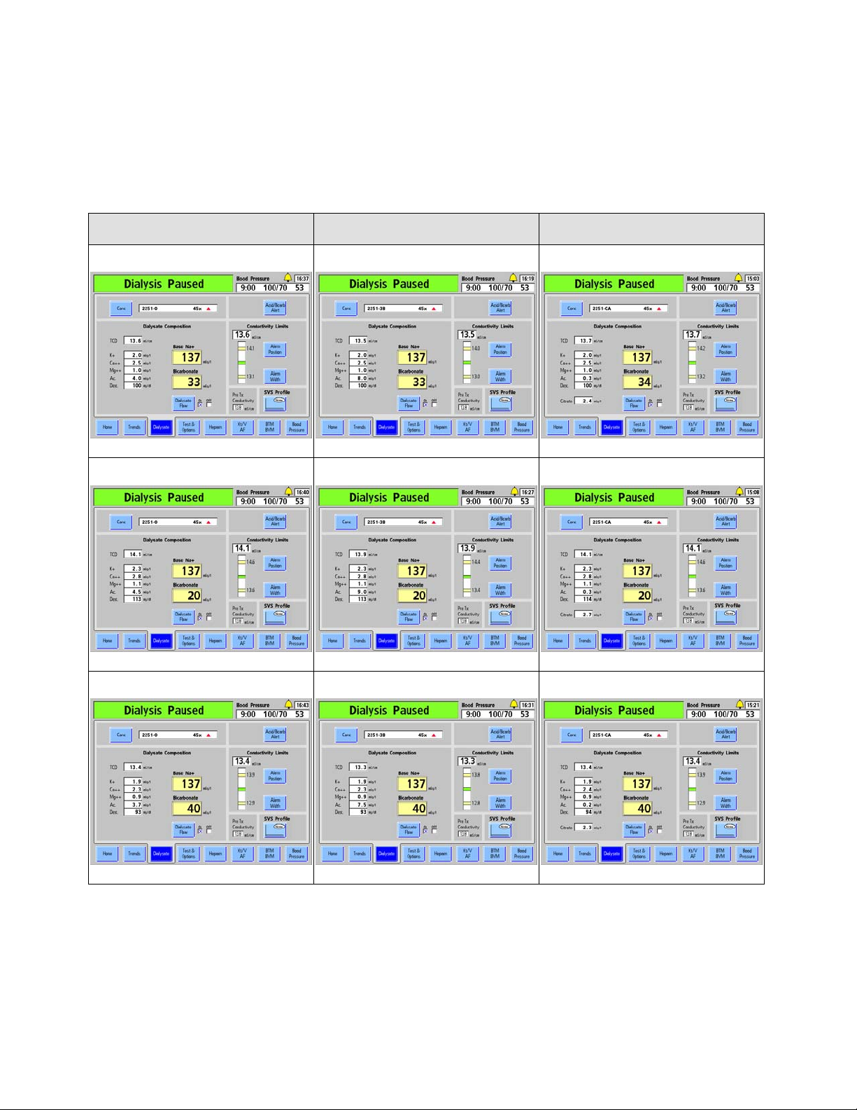
Chapter 3—Setting Treatment Parameters
The following table shows the full extent of those changes to the electrolyte constituents in
the Final Dialysate composition with sodium (Base Na+) at 137 mEq/L and post-reaction
bicarbonate at 33 mEq/L (34 mEq/L for Citrasate), 20 mEq/L, and 40 mEq/L:
Table 14 – Example of “Dialysate” Screen Dialysate Composition Ranges with Sodium
Constant at 137 mEq/L
NaturaLyte® GranuFlo® Citrasate®
Nominal Bicarbonate Setting
Minimum Bicarbonate Setting
Maximum Bicarbonate Setting
Nominal Bicarbonate Setting
Minimum Bicarbonate Setting
Maximum Bicarbonate Setting
Nominal Bicarbonate Setting
Minimum Bicarbonate Setting
Maximum Bicarbonate Setting
86 2008T Machine Operator’s Manual P/N 490122 Rev U

Setting an Acid/Bicarbonate Type
Acid concentrates for use in Dialysis/SLED are selected ahead of time in Service Mode. The
acid and bicarbonate concentrate types are paired together when setting dialysate parameters
on the “Dialysate” screen. If the current patient’s prescribed dialysate differs from the
previous patient’s, or if the machine is new or has been recalibrated, a new acid/bicarbonate
concentrate type matching the dialysate prescribed by the current patient’s physician must be
entered.
To enter the acid/bicarbonate concentrate type:
1) From the
“Dialysate” screen,
select the Conc
button. The
“Concentrate”
subscreen opens.
Chapter 3—Setting Treatment Parameters
Figure 39 – Enter Acid & Bicarbonate Type
2008T Machine Operator’s Manual P/N 490122 Rev U 87

Chapter 3—Setting Treatment Parameters
1) The electrolyte profile of the
highlighted selection is
displayed in this column.
Note: If the machine is set up
for use with Citrasate a
‘Citrate’ meter box will be
displayed in the dialysate
constituent list.
2) Highlight the desired
selection by scrolling through
the choices using the or
(up or down) keys on the
keyboard.
3) When the desired type is highlighted, press
the Enter key or CONFIRM key on the Touchpad
to save the selection and return to the “Dialysate”
screen.
Note: Be sure the acid/bicarbonate concentrates
connected to the machine match the type
selected from the Concentrate menu.
4) Enter the prescribed Base Na+
and Bicarbonate values as described
in “Entering a Treatment Parameter”
on page 79.
Figure 40 – Entering Concentrate Information
88 2008T Machine Operator’s Manual P/N 490122 Rev U

Chapter 3—Setting Treatment Parameters
Setting the Acid/Bicarbonate Alert
The Acid/Bicarbonate Alert option sounds an alarm when the fluid level in either of the
concentrate jugs has been drained to 20 percent of its original amount. In addition to the
alarm, a Low Alarm message such as “
appear in the Status Box. This alert aids the operator in maintaining adequate amounts of
concentrate in the containers during treatment. Be sure to set the new volume in this screen
whenever the concentrate containers are refilled.
1) From the “Dialysate”
screen, select Acid/Bicarb
Alert. The “Acid/Bicarb
Alert” subscreen appears.
Low Acid Warning” or “Low Bicarb Warn” will
2) Select Acid. Using the keyboard, enter the actual
amount, in liters, of concentrate in the acid jug.
3) Select Bicarbonate. Using the keyboard,
enter the actual amount, in liters, of
concentrate in the bicarbonate jug.
Note: If the facility is
on a centralized acid
or bicarbonate supply
system, enter zero to
deactivate the alarm
for that concentrate.
6) Select Dialysate to exit the
“Acid/Bicarb Alert” subscreen.
The volume of each concentrate
will count down as it is used.
Figure 41 – Setting Acid & Bicarbonate Alerts
4) Select Alert until an X
appears in the On checkbox.
5) Press CONFIRM to
save the change.
2008T Machine Operator’s Manual P/N 490122 Rev U 89
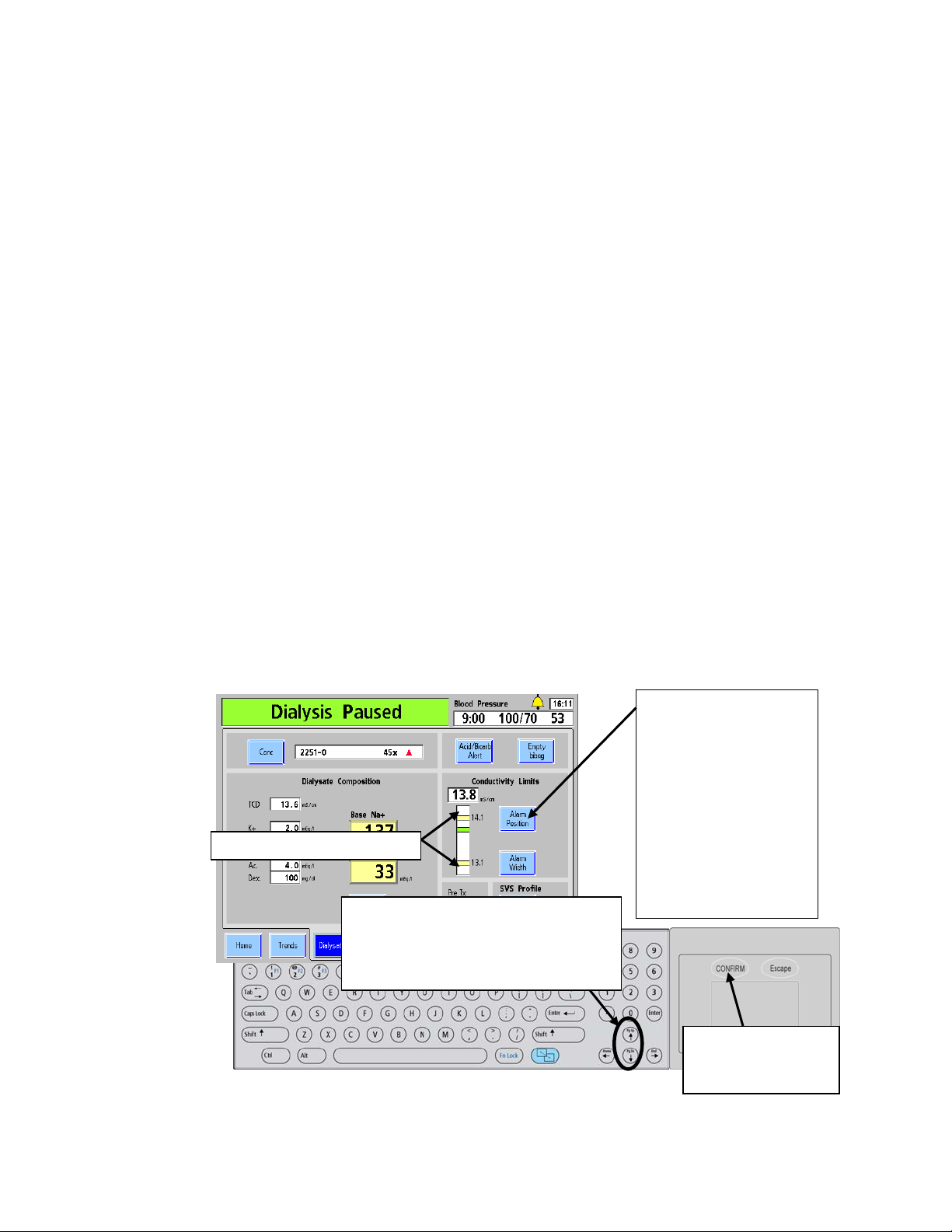
Chapter 3—Setting Treatment Parameters
Conductivity
The Theoretical Conductivity (TCD) represents the expected conductivity for the selected
concentrate at the set Na+ and bicarbonate levels. It is displayed above the electrolyte
constituents on the left side of the “Dialysate” screen (see Figure 38 on page 82). The actual
conductivity of the Final Dialysate is displayed above the conductivity bar graph on the right
side of the “Dialysate screen.” It is represented by a horizontal bar in the conductivity graph.
The bar appears green when the conductivity is within alarm limits, and turns red when the
actual conductivity is outside the alarm window. With both concentrate supplies connected
to the machine, a stable, accurate conductivity reading should be attained about five minutes
after the concentrate is confirmed in the “Dialysate” screen.
If the ‘Independent Conductivity’ Service Mode option is set, the machine’s independent
conductivity reading is also displayed on the “Dialysate” screen under the heading “Pre Tx
Conductivity” (see Figure 38 on page 82).
Conductivity Limits
As the operator changes the sodium or bicarbonate settings, the TCD (Theoretical
Conductivity) will change. The alarm limits are set around the TCD. The alarm window is
the area between the upper and lower alarm limits. The upper and lower alarm limits are
shown by yellow horizontal lines in the conductivity bar graph. They are set 0.5 mS/cm
above and below the TCD by default. The conductivity alarm sounds when the actual
conductivity of the dialysate climbs or falls outside of this window. The alarm window can be
shifted up or down to within 0.5 mS/cm of the default setting using the Alarm Position
button (and the keyboard), and widened or narrowed using the Alarm Width button (and the
keyboard). The width of the alarm window can be set from a minimum of 0.6 mS/cm to a
maximum of 1.0 mS/cm, within the range of 12.5–16.0 mS/cm.
The following examples illustrate how to set the conductivity alarm window:
Upper and lower alarm limits
2) To shift the alarm window upward,
press the (up) arrow key. To shift
the window downward, press the
(down) arrow key.
Figure 42 – Changing Conductivity Limits
1) To access the
position of the
conductivity alarm
window, select Alarm
Position.
Note: If the Service
Mode ‘Cond Alarm
Position’ option is set to
‘Locked’, this button is
un-selectable and the
alarm position cannot be
adjusted.
3) Press the
CONFIRM key to
save the change.
90 2008T Machine Operator’s Manual P/N 490122 Rev U

Chapter 3—Setting Treatment Parameters
Conductivity Alarm Window
1) To access the
conductivity alarm window,
select Alarm Width.
2) Press the (up) arrow key to
increase the distance between
the upper and lower alarm limits.
Press the (down) arrow key to
decrease it.
3) Press CONFIRM
to save the new
alarm settings.
Figure 43 – Changing Conductivity Limit Width
Warning! Always verify the conductivity and approximate pH of the dialysate solution
through independent means before initiating each dialysis treatment. Independent means
could be by using an external conductivity meter, pH meter, pH paper or by using the
machine’s independent conductivity test. An approximate pH check is also part of the
machine’s independent conductivty test when a bibag disposable is connected. Verify that
the conductivity is within 0.4 mS/cm of the theoretical conductivity value (TCD) and the pH
is between 6.9 and 7.6 if using a pH meter or pH paper. If conductivity and pH are not
within these limits, do not initiate dialysis. The machine’s independent conductivity test
relies on the use of prequalified manufactured acid concentrates or verified batch
concentrates; the pH check relies on the use of these concentrates and the bibag. It is the
responsibility of the user to ensure that non-prequalified manufactured acid concentrates
have the correct pH. For more information on collecting a dialysate sample for external
testing, see “Testing the Dialysate” on page 347.
2008T Machine Operator’s Manual P/N 490122 Rev U 91

Chapter 3—Setting Treatment Parameters
Home Screen Settings
After entering the data in the “Dialysate” screen, treatment parameters regarding treatment
length, ultrafiltration, and the administration of sodium can be entered in the “Home” screen.
The “Home” screen can also provide a view of the status of the treatment once it has begun
(see “Home Screen Monitoring” on page 137). Unless otherwise described, enter or change a
dialysate-related value by following the procedure described in “Entering a Parameter” on
page 79.
Note: The 2008T hemodialysis machine is equipped with both visual cues and audible
alarms to alert the operator to potential problems. In every alarm condition, assess the
patient for any changes in his/her physiologic state. Ensure that the patient’s access is
exposed and all connections in the extracorporeal circuit are secure and visible during the
entire procedure. It is the responsibility of the dialysis personnel to provide safe and
effective dialysis treatment. Document all unusual events.
Figure 44 – The Home Screen (showing functional software version 2.72 or later)
92 2008T Machine Operator’s Manual P/N 490122 Rev U

Chapter 3—Setting Treatment Parameters
What to do from this screen…
Enter the prescribed treatment settings for:
UF Goal
UF Time
Check UF Rate (Calculated from UF Goal and UF time)
Dialysate Flow
Dialysate Temperature
Treatment Time (RTD) (optional; RTD will transfer from UF time if UF removed is 0
when UF is turned on.)
Start or pause the Tx Clock
Set the speed of the blood pump
If prescribed, access the proper screen to set treatment parameters for:
UF profile
Sodium Variation (SVS) profile
The following table provides a description of the data buttons available in the “Home” screen.
Table 15 – The Home Screen Features
Feature Function
The amount of fluid (in ml) to be removed during the entire treatment is
entered here. This button is also available in the “UF Profile” subscreen
if a profile is to be used to vary the rate of ultrafiltration during
treatment. If the UF Goal is set to zero, the UF Time will also change to
zero; the UF Rate may then be set independent of UF Time and UF
Goal.
Note: Setting the UF Goal to zero while the blood pump is
still running will cause the UF Rate to be set to a minimum
of 10 ml/hr. If the blood pump is stopped, setting the UF
Goal to zero causes the UF Rate to be set to a minimum of
70 ml/hr (or 300 ml/hr if the High Flux option is set on the
Test & Options screen). To stop ultrafiltration entirely (with
a UF Rate of zero), simply press the UF on/off key on the
control panel keypad to set it to 'off'.
The length of treatment time during which ultrafiltration will occur is
entered here in hours and minutes (hr: min). UF Time will generally be
equal to treatment time and will automatically transfer to the RTD
button. Once treatment begins, this button acts as a countdown timer
indicating the amount of time left for ultrafiltration. This time can be
increased or decreased by the operator at any time. Changing the UF
Time or UF Goal will change the UF Rate accordingly except when the
UF Goal is set to zero. If the UF Rate is adjusted, the UF Time will be
automatically calculated without affecting the UF Goal. To run Isolated
Ultrafiltration, see “Running Isolated UF as Sequential Dialysis” on
page 100. Blood alarms or online pressure holding tests temporarily
stop this timer.
2008T Machine Operator’s Manual P/N 490122 Rev U 93

Chapter 3—Setting Treatment Parameters
Feature Function
Enter here, in 10 ml/hr increments, the rate fluid will be drawn from the
patient (ultrafiltration). Generally the UF rate is not entered, but rather
automatically calculated from the UF Goal and UF Time. If the UF Rate
value is manually changed, the UF Time value will automatically
change accordingly.
Displays the total amount of ultrafiltration removed in ml. The counter
keeps track of the UF in 1 ml increments.
The prescribed dialysate flow rate, in ml/min, is entered here. The rate,
displayed in ml/min, can be entered from 0 to 800 in increments of 100
(plus the setting of 150 ml/min). If flow is set for sequential dialysis
(Isolated UF), the button displays ‘SEQ’. For more information on
sequential dialysis, see page 100.
To turn off dialysate flow, select the Dialysate Flow button and either
use the key to scroll down to OFF or press the 0 key and then press
the CONFIRM key. To turn dialysate flow back on, select the Dialysate
Flow button, set it to the desired value, and press the CONFIRM key.
Warning! UF Removed must be reset to 0 before initiating
treatment. If the UF Removed is not reset, the amount
displayed will be used in the UF calculation, resulting in
incorrect UF removal from the patient.
1.5x or 2x auto flow may be selected by scrolling up past 800. If this
automatic selection is set, the dialysate flow rate will be set to
approximately 1.5 or 2 times the blood flow rate between 500 and 800
ml/min, in 100 ml/min increments. When 1.5x or 2x is selected and
confirmed, the dialysate flow rate will be indicated with the letter “a”
preceding the dialysate flow rate, such as: “a500”.
Note: Dialysate flow changes are generally delayed about 30
Note: With Auto Flow, even though the dialysate flow is
Warning! Setting the dialysate flow to a rate that is too low
can adversely affect dialyzer clearance and reduce treatment
efficacy. If 1.5x or 2x selects a flow rate below that
prescribed, the dialysate flow may be manually set to the
desired value.
Note: The value displayed in the Dialysate Flow button will
flash when dialysate flow is set to ‘OFF’ from the “Dialysate”
screen (see page 82 for more information). Select the
Dialysate Flow toggle-button and press the CONFIRM key
to turn the dialysate flow back on when desired.
seconds after a change in the blood pump rate to prevent
unnecessary flow adjustments during priming and to allow
the machine to stabilize before determining the new dialysate
flow rate.
expressed as a multiple of the blood flow rate, the dialysate
flow is not exactly the calculated multiple of the blood flow.
The dialysate flow changes in increments of 100 ml/min only.
In order to be conservative with lower dialysate flow rates,
each transition point to the next higher dialysate flow rate is
somewhat earlier than one would calculate. See the table on
page 352 for more details.
94 2008T Machine Operator’s Manual P/N 490122 Rev U

Feature Function
The desired temperature of the dialysate in degrees Celsius is set here.
Once this setting is confirmed, the button will display the actual
temperature. The allowable temperature setting range from 35 C to 39
C. A temperature alarm occurs when the actual temperature rises or
falls 2 C beyond the set temperature. If the dialysate flow is set to
OFF or SEQ, the temperature is “N/A”, since there is no dialysate flow.
The actual conductivity is displayed here. Selecting this button displays
the “Dialysate” screen where the Theoretical Conductivity (TCD) is
displayed for the selected concentrates settings. See page 81 for more
information.
RTD (Remaining Time of Dialysis)—At the start of the treatment, the
time entered in the UF Time button is automatically transferred to the
RTD button if UF removed is 0. If it is necessary to change the
treatment time, RTD can be entered here. A dialysate or blood alarm
will stop this timer.
Ultrafiltration (UF) Profile—Opens the “UF Profile” subscreen from
which a profile for executing variable rate ultrafiltration can be selected.
The button displays the current profile selection. For more information,
see “Setting a UF Profile” on page 97.
Sodium Variation System (SVS) Profile—This button opens the “SVS
Profile” subscreen from which the operator can select how sodium is
varied during the course of the treatment. For more information, see
“Sodium Variation System” on page 102. This button is colored green
when an SVS profile is running (functional software version 2.34 or
later).
If the SVS option is set to ‘No’ in Service Mode, this button will not be
displayed.
The Treatment Clock button is selected and confirmed to start or
pause the treatment. The green segment of the pie chart represents
the amount of treatment completed. The green segment grows as the
treatment progresses. The circle will be completely green when RTD is
equal to zero. During treatment, this button displays the message, “Tx
Running.”
Selecting and confirming this button will pause the treatment clock and
the button will display the message, “Tx Paused.” When the treatment
is paused, the RTD, heparin infusion time, and UF time each stop
counting down, the UF and heparin pumps stop, and the SVS time is
paused. The UF key LED indicators will flash. Turning the Treatment
Clock back on will restore operation of these parameters unless turned
off with the respective front panel on/off key or on-screen button.
The first time the Treatment Clock is turned on, the UF Removed is
reset to 0 and the UF, Heparin pumps and SVS & UF programs are
turned on and a blood pressure reading is taken, if applicable.
Chapter 3—Setting Treatment Parameters
Blood Pump Rate—Displays the speed of the blood pump and allows
the operator to set it from the display screen in addition to the module.
The rate, displayed in ml/min, can be entered from 0 to 600 in Dialysis
or 0 to 300 in SLED in increments of 5. Setting the blood flow rate to
zero will stop the blood pump. The blood flow rate flashes when the
blood pump is stopped.
2008T Machine Operator’s Manual P/N 490122 Rev U 95

Chapter 3—Setting Treatment Parameters
Table 16 – UF Control Key
Key Function
The UF on/off key turns the ultrafiltration pump on or off. During
ultrafiltration, the green light is illuminated.
This light flashes when ultrafiltration is interrupted, and the UF Time
countdown stops. Operation will resume when the Treatment Clock is
turned on or the UF on/off key is pressed.
If the UF on/off key is pressed during dialysis to turn off the UF pump,
it will not resume with the Treatment Clock button.
96 2008T Machine Operator’s Manual P/N 490122 Rev U

Ultrafiltration
Use the UF Goal and UF Time buttons to determine the necessary UF rate for the treatment.
The maximum UF rate (set in Service Mode) is limited to between 1000 ml/hr or 4000 ml/hr
(at 1000 ml/hr intervals), depending on the option selected. The UF Goal is limited to 9990
ml. Reset the UF removed to zero after setting the UF time. The ultrafiltration will be at a
steady rate throughout the treatment. When the UF on/off key is turned off, no ultrafiltration
is occurring. When the Tx Clock button is turned on, the UF pump (as well as a number of
other functions) is automatically started. When the UF goal has been achieved, the UF time
is set to 0:00, and the UF rate goes to 70 ml/hr (conventional dialyzers) or 300 ml/hr (high
flux dialyzers). If a profile (variation during treatment) is desired for the UF rate, use the UF
Profile button.
Warning! When using high-flux dialyzers with low UF rates there is a possibility of back-
filtration. Back filtration depends on: type of high-flux dialyzer, flow resistance on dialysate
and blood sides, and blood viscosity.
Chapter 3—Setting Treatment Parameters
Warning! Weigh the dialysis patient before and after treatment to check against fluid
removal discrepancies.
Setting a UF Profile
The different UF Profiles available are used to improve patient comfort during dialysis by
providing alternating patterns of high and low rates of ultrafiltration. This also allows the
fluid in the patient to equilibrate more completely between the intracellular and extracellular
compartments. A UF profile divides the UF Time into twelve equal segments of differing UF
rates, based on the profile, in order to reach the prescribed UF Goal.
To view the available profiles, select the UF Profile button on the “Home” screen. The “UF
Profile” subscreen (see Figure 46) will open displaying up to eight possible profiles and a
selection for “None.” The first four profiles are standard profiles. The fifth through eighth
profiles are programmable to meet the needs of the clinic.
Table 17 – The UF Profile Subscreen Buttons
Button Function
Profile 1 – Increases the UF rate for approximately the first 40% of
the treatment then gradually decreases
2008T Machine Operator’s Manual P/N 490122 Rev U 97

Chapter 3—Setting Treatment Parameters
Button Function
Profile 2 – Aggressive level UF with a gradual decline.
Profile 3 – Moderate level UF increase throughout approximately
the first 60% of treatment and declines to a minimum.
Profile 4 – Low-level UF moving into a series of decreasing peaks
and valleys for the first two-thirds of the treatment followed by a
plateau of moderate UF to completion.
Profiles 5, 6, 7, 8 – Customizable in Service Mode, see page 331
for more information. The images on these buttons will match the
appearance of the customized profiles.
None – Ultrafiltration occurs at a constant minimum rate calculated
from the set UF Time in order to reach the set UF Goal. It does not
mean that no ultrafiltration will occur.
UF Goal – This is the value from the “Home” screen, see page 93
for more information.
Maximum UF Rate – Once the UF Goal and UF Time are entered,
the Maximum UF Rate for the selected profile is calculated and
displayed here. The calculated rate cannot exceed the Maximum
UF Rate limit set in Service Mode, see “Max UF Rate” on page 323.
UF Time – This is the value from the “Home” screen, see page 93
for more information. When a UF profile is selected and confirmed,
the machine will apply the new UF profile to the remaining UF time
in twelve equal segments.
Note: Any of the four customizable profiles (5 through 8) that are not programmed will
function the same as the None profile. See “UF Profile Screen: Creating Custom UF
Profiles” on page 331 for instructions on how to customize these profiles.
To initiate an ultrafiltration profile, select one of the profiles by selecting the appropriate
button. Enter the desired UF Goal and UF Time values using the numeric keys or the or
(up or down) keys on the keyboard and confirming with the Enter or CONFIRM keys.
The UF Goal and UF Time values from the “Home” screen will appear in the “UF Profiles”
subscreen. Once the UF Goal and UF Time are entered, the Maximum UF Rate for the
selected profile is calculated and displayed in the corresponding text box on the screen.
98 2008T Machine Operator’s Manual P/N 490122 Rev U

To enter an ultrafiltration profile:
1) From the Home or SVS
Profile screen, select UF Profile
to open the “UF Profile” screen.
Chapter 3—Setting Treatment Parameters
Figure 45 – Setting a UF Profile
2) Select the profile
button that
graphically
represents the
prescribed manner
in which
ultrafiltration is to be
carried out. An
enlarged view of the
selected profile will
appear on the right
side of the
subscreen.
Figure 46 – Setting UF Profile Parameters
This button (UF Profile
in the “Home” screen)
changes to the selected
profile when selection is
confirmed.
3) If not previously
entered from the
“Home” screen,
enter the UF Goal
and UF Time
values (see
“Entering a
Treatment
Parameter” on
page 79).
4) Press
CONFIRM.
2008T Machine Operator’s Manual P/N 490122 Rev U 99

Chapter 3—Setting Treatment Parameters
Note: The “None” profile performs ultrafiltration at a constant rate. It does not mean that no
ultrafiltration will occur.
The maximum UF rate is displayed for the selected profile, UF Goal, and UF Time. If the
maximum UF Rate is too high (beyond the configuration of the machine), a message appears
in the Dialogue Box located in the upper, right corner of the screen. The operator has the
option of increasing the UF Time, reducing the UF Goal, or selecting another profile.
To change the profile, select the corresponding profile button.
To change the time, select the UF Time button.
To change the UF goal, select the UF Goal button. The maximum ultrafiltration rate,
based on the UF Goal, Time & Profile, will be calculated and displayed in the Maximum
UF-Rate display.
When all ultrafiltration parameters are satisfactory, press CONFIRM to save the changes,
then exit from the “UF Profile” screen. The machine will apply the new UF profile to the
remaining UF time in twelve equal segments.
Isolated Ultrafiltration
Isolated Ultrafiltration (UF) is sometimes prescribed for patients suffering from excessive
fluid retention. During Isolated UF the machine does not run dialysate through the dialyzer,
it performs only ultrafiltration, pulling the patient’s excessive fluid from the bloodstream via
the dialyzer with no diffusion.
Running Isolated UF as Sequential Dialysis
Isolated UF is performed using the “SEQ” (Sequential) setting on the “Home” screen’s
Dialysate Flow button. Sequential dialysis refers to a two-stage treatment in which one of the
stages consists solely of Isolated UF followed by hemodialysis. Using Sequential dialysis,
Isolated UF is usually performed at the beginning of a standard dialysis treatment, although it
can also be administered during treatment. The operator can start or stop the Isolated UF
option at any time. After 60 minutes of Isolated UF, the machine will notify the operator that
dialysate flow has been off for 60 minutes. At that time, the operator must choose to turn on
dialysate flow and begin hemodialysis or to continue with Isolated UF
Note: Setting and confirming the Dialysate Flow to ‘0’ will turn it OFF instead of running
sequential dialysis. After five minutes of Isolated UF, an alarm sounds and the Low Alarm
message, “5 Minutes Flow Off,” appears in the Status Box. The operator has the option of
continuing Isolated UF or starting dialysis. This alarm occurs only once.
100 2008T Machine Operator’s Manual P/N 490122 Rev U
 Loading...