

Page 1
©2013 Fresca ™ All rights reserved. This material may not be reproduced, displayed, modified or distributed without the express prior written permission of the copyright holder.
FSP8006
VERONA
INSTALLATION GUIDE
PAGE 1
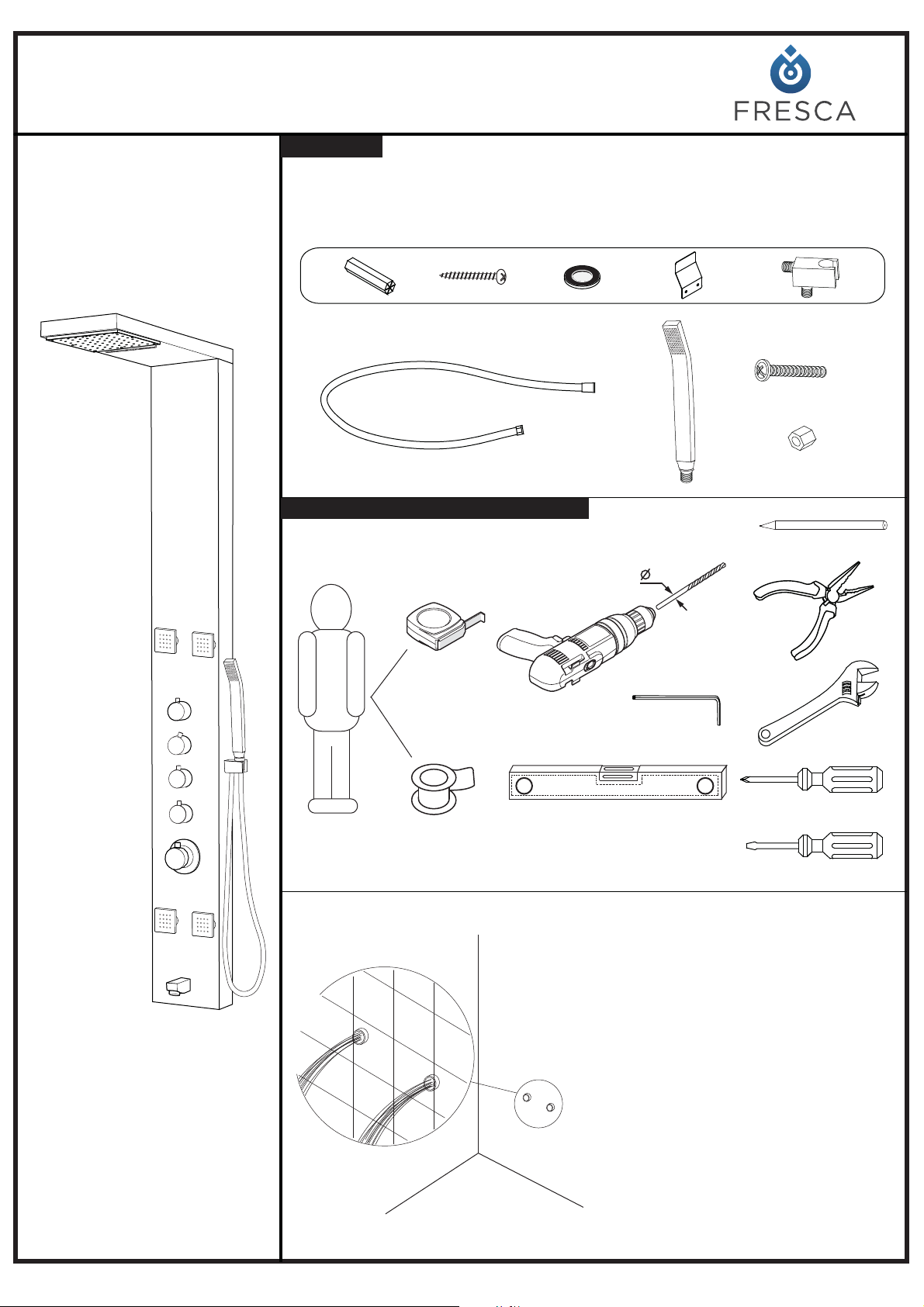
Parts List
For lnstallation Yon may Require
Please unpack and inspect all packages and components carefully,
make sure they are complete. Examine for shipping damage. If some
parts are damaged or missing, notify your dealer immediately.
6
Before assembly, flush the water
supply pipes thoroughly to
remove debris(allow the water to
run with the main stopcock open
for about 3 mins), otherwise dirt
particles might affect the function
of the shower panel!
Note!
Page 2
©2013 Fresca ™ All rights reserved. This material may not be reproduced, displayed, modified or distributed without the express prior written permission of the copyright holder.
PAGE 2
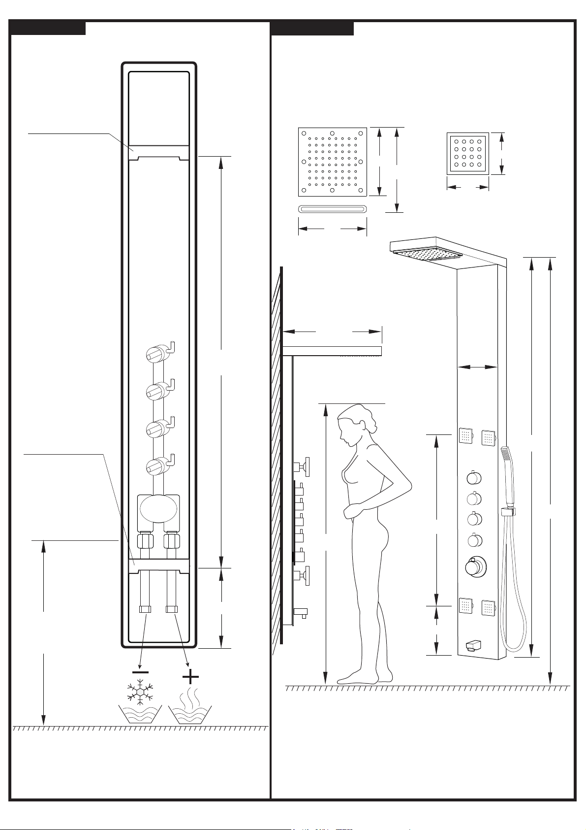
Dimensions
Back View
Measure the distance from the upper fixing
hanger to the lower fixing hanger. The
dimensions are for your reference only.
"
5 3/4
"
46 7/8
"48
UPPER HANGING
BRACKET
LOWER HANGING
BRACKET
Recommended
height
Cold inlet
Hot inlet
SHOWERHEAD
MASSAGE JET
Choose a suitable place to install the shower
panel, adjust the shower panel’s vertical position
based on the user’s height and your sanitary room.
Usually, install the panels at the distance of
82 3/5 from the top to the ground, but you
can assemble according to your instance.
"
"7
"2
"
2
"
7
"
10
The height can be altered to suit individual
requirements.
The dimensions are for reference only.
"70
"
8
"
23 3/4
"
60 1/4
"
7
82 3/5
Note!
"
"
20 1/4
Page 3
©2013 Fresca ™ All rights reserved. This material may not be reproduced, displayed, modified or distributed without the express prior written permission of the copyright holder.
PAGE 3
Note!
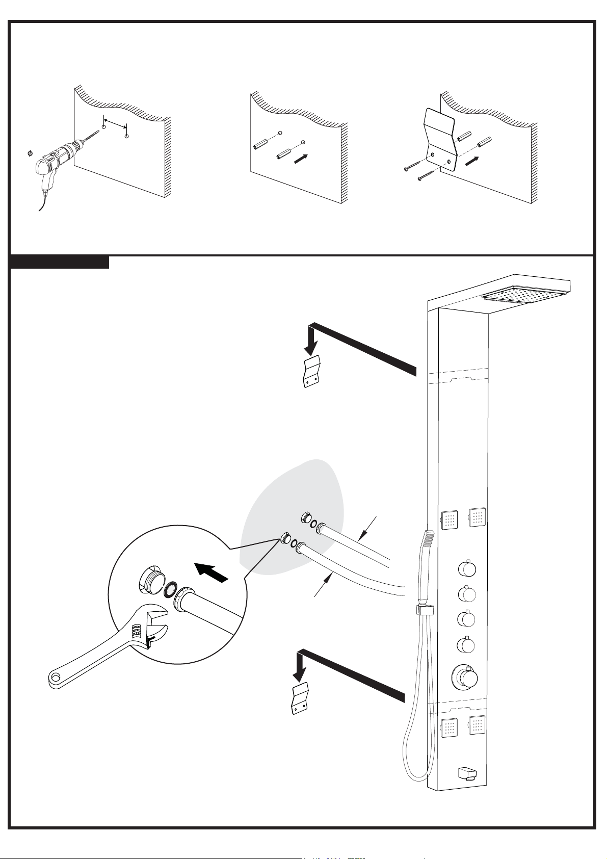
Before drilling any holes for fixing your shower panel ensure that
there are no hidden cables or pipework within the wall.
COLD
HOT
Wall-mounting
6
mm Drill
Insert the wall plugs inside
the holes
Tighten the screws to the wall
with wall mounting brackets
1
2
3
wall wall wall
25
mm
Drill the holes in the wall
Your item may appear slightly different from the illustration
Hang the shower panel on the mounting bracket
Page 4
©2013 Fresca ™ All rights reserved. This material may not be reproduced, displayed, modified or distributed without the express prior written permission of the copyright holder.
PAGE 4
Corner-mounting
30 10
+
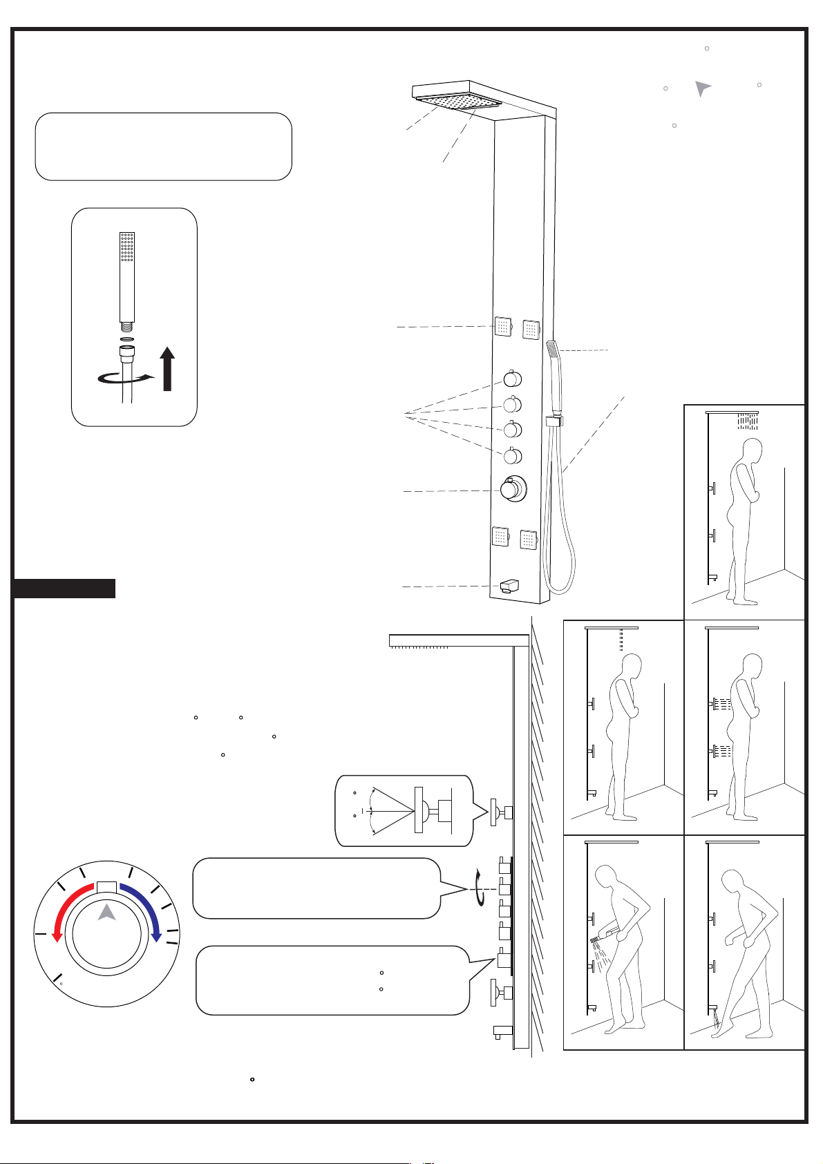
The temperature has been pre-setted
at a safe temperature 104 F with the
safety push button to 104 F.
Select the shower function
required and adjust the flow-rate
by rotating the control knobs.
Note!
Note!
Don’t forget to place the rubber
washer when it is necessary.lt
will avoid water leakage.
head shower
waterfall
hand shower
1.5m stainless steel hose
4 massage jets
volume controls
thermostatic faucet
spout
The shower panel is for indoors use only. For outdoors use please refer
to the “Fresca”outdoors shower panel series.
If the safety push button has been operated, it is important that it is returned to its
original position(100.4 F) in order to prevent the next shower user from accidental
scalding if the temperature is too high.
Thermostatic
Control
1
2
2
F
1
1
3
F
1
0
0
.
4
F
9
5
F
8
6
F
Operation
Technical data
Minimum working pressure 11.6 PSI
Maximum working pressure 72.5 PSI
Recommended operating pressure
21.75 PSI - 43.5 PSI
Test pressure 145 PSI
Temperature scale 86 F-122 F
Hot water temperature Max. 158 F
Safety stop 100.4 F
Thermostatic Control
F
To change the water temperature,
please push the button and turn
knob accordingly.
1
2
2
1
1
3
1
0
0
.
4
9
5
8
6
Page 5
©2013 Fresca ™ All rights reserved. This material may not be reproduced, displayed, modified or distributed without the express prior written permission of the copyright holder.
PAGE 5
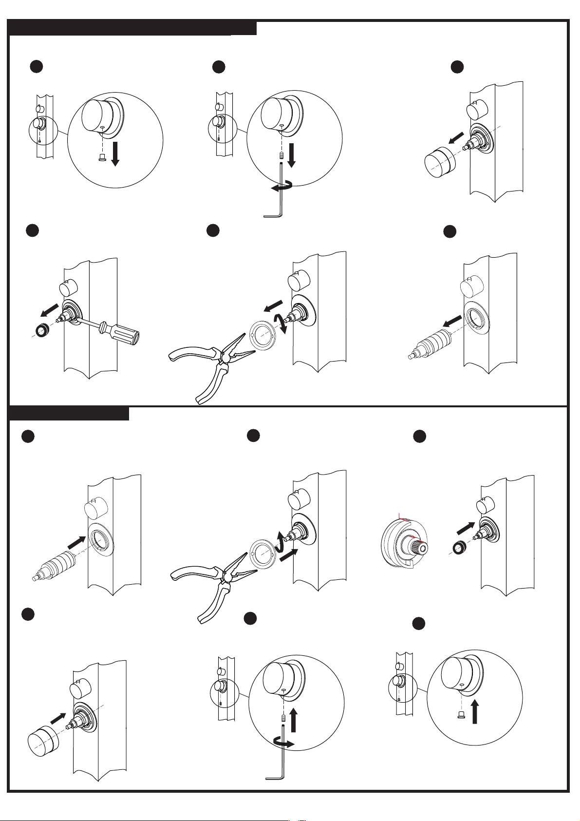
Take off cap
Remove process
Thermostatic valve removal and installation
Place valve in place(ensure
the screw head pointing to
the cut off of the plated ring)
Press the button on the head
and put on the head as
below ensuring the screw
hole pointing to the front
Use allen wrech to fix the
HEX screw tightenly
Put on cap
Remove the valve
Put golden ring
on top of valve
Loosen HEX screw off with allen
wrench
Take off plastic ring
Position on the golden ring and pull out
the valve by needle nose pliers
Take off head
1
1
2
2
3
3
4
4
5
5
6
6
Installation process
Put plastic ring in place
with a rubber hammer
(align the red marks in
line)
 Loading...