

SPPDF 01 Development Suite
User’s Manual
For SPPDM-01 FIR Filter Platform

25 Locust St, Haverhill, Massachusetts 01830 • Tel: 800/252-7074, 978/374-0761 • FAX: 978/521-1839
e-mail: sales@freqdev.com • Web Address: http://www.freqdev.com
SPPDF 01 Development Suite
User’s Manual
Table of Contents
Chapter I - Introduction . . . . . . . . . . . . . . . . . . . . . . . . . . . . . . . . . . . . . . . . . . . . . . . . . . . . . . . . . . . . . . . .Page
1.1. Hardware Description . . . . . . . . . . . . . . . . . . . . . . . . . . . . . . . . . . . . . . . . . . . . . . . . . . . . . . . . . . . . . 3
1.2. Software Description . . . . . . . . . . . . . . . . . . . . . . . . . . . . . . . . . . . . . . . . . . . . . . . . . . . . . . . . . . . . . . 5
Chapter II - Filter Coefficient Generator
2.1. Filter Coefficient Generator Installation and Startup . . . . . . . . . . . . . . . . . . . . . . . . . . . . . . . . . . . . . . . 6
2.2. Filter Coefficient Generator GUI Control Group Descriptions . . . . . . . . . . . . . . . . . . . . . . . . . . . . . . . .6
Chapter III – Filter Coefficient Loader
3.1. Filter Coefficient Loader Equipment Required . . . . . . . . . . . . . . . . . . . . . . . . . . . . . . . . . . . . . . . . . . .10
3.2. Filter Coefficient Loader Installation and Startup . . . . . . . . . . . . . . . . . . . . . . . . . . . . . . . . . . . . . . . . .10
3.3. Filter Coefficient Loader GUI Main Panel Description . . . . . . . . . . . . . . . . . . . . . . . . . . . . . . . . . . . . .11
Appendix
A. Example 1 -- Manual FIR Filter Selection . . . . . . . . . . . . . . . . . . . . . . . . . . . . . . . . . . . . . . . . . . . . . . .15
Example 2 – Filter Coefficient Generator, Immediate Mode Operation
Single Set Coefficient . . . . . . . . . . . . . . . . . . . . . . . . . . . . . . . . . . . . . . . . . . . . . . . . . . . .16
Example 3 - Filter Coefficient Generator, Immediate Mode Operation
Multiple Coefficient Sets . . . . . . . . . . . . . . . . . . . . . . . . . . . . . . . . . . . . . . . . . . . . . . . . . .19
Example 4 – Filter Coefficient Loader, Batch Mode Operation
Single Set Coefficient . . . . . . . . . . . . . . . . . . . . . . . . . . . . . . . . . . . . . . . . . . . . . . . . . . . .22
Example 5 – Filter Coefficient Loader, Batch Mode Operation
Multiple Coefficient Sets . . . . . . . . . . . . . . . . . . . . . . . . . . . . . . . . . . . . . . . . . . . . . . . . . .24
B. Software Plug . . . . . . . . . . . . . . . . . . . . . . . . . . . . . . . . . . . . . . . . . . . . . . . . . . . . . . . . . . . . . . . . . . .26
C. Field Programming Circuit for SPPDM-01 . . . . . . . . . . . . . . . . . . . . . . . . . . . . . . . . . . . . . . . . . . . . . . .32
List of Figures
1. SPPDF-01 Hardware Configuration . . . . . . . . . . . . . . . . . . . . . . . . . . . . . . . . . . . . . . . . . . . . . . . . . . . . 4
2. Filter Coefficient Generator Main Panel . . . . . . . . . . . . . . . . . . . . . . . . . . . . . . . . . . . . . . . . . . . . . . . . . 6
3. Filter Coefficient Loader GUI Main Panel . . . . . . . . . . . . . . . . . . . . . . . . . . . . . . . . . . . . . . . . . . . . . . . .11
4. Filter Coefficient Generator Display – Immediate Mode Operation,
Single Coefficient Sets . . . . . . . . . . . . . . . . . . . . . . . . . . . . . . . . . . . . . . . . . . . . . . . . . . . . . . . . . . . . .16
5. Amplitude/Phase Plot – Immediate Mode Operation,
Single Coefficient Sets . . . . . . . . . . . . . . . . . . . . . . . . . . . . . . . . . . . . . . . . . . . . . . . . . . . . . . . . . . . . .17
6. Filter Coefficient Generator Display – Immediate Mode Operation,
Multiple Coefficient Sets . . . . . . . . . . . . . . . . . . . . . . . . . . . . . . . . . . . . . . . . . . . . . . . . . . . . . . . . . . . .19
7. Amplitude/Phase plot – Immediate Mode Operation,
Multiple Coefficient Sets . . . . . . . . . . . . . . . . . . . . . . . . . . . . . . . . . . . . . . . . . . . . . . . . . . . . . . . . . . . .20
8. Filter Coefficient Loader – Batch Mode Operation,
Single Coefficient Sets . . . . . . . . . . . . . . . . . . . . . . . . . . . . . . . . . . . . . . . . . . . . . . . . . . . . . . . . . . . . .22
9. Filter Coefficient Loader – Batch Mode Operation,
Multiple Coefficient Sets . . . . . . . . . . . . . . . . . . . . . . . . . . . . . . . . . . . . . . . . . . . . . . . . . . . . . . . . . . . .24
10. Required circuit to provide coefficient memory access
for the SPPDM-01 family of products . . . . . . . . . . . . . . . . . . . . . . . . . . . . . . . . . . . . . . . . . . . . . . . . . . .32

25 Locust St, Haverhill, Massachusetts 01830 • Tel: 800/252-7074, 978/374-0761 • FAX: 978/521-1839
e-mail: sales@freqdev.com • Web Address: http://www.freqdev.com
SPPDF-01 Development Suite
User’s Manual
Introduction
Chapter I
3
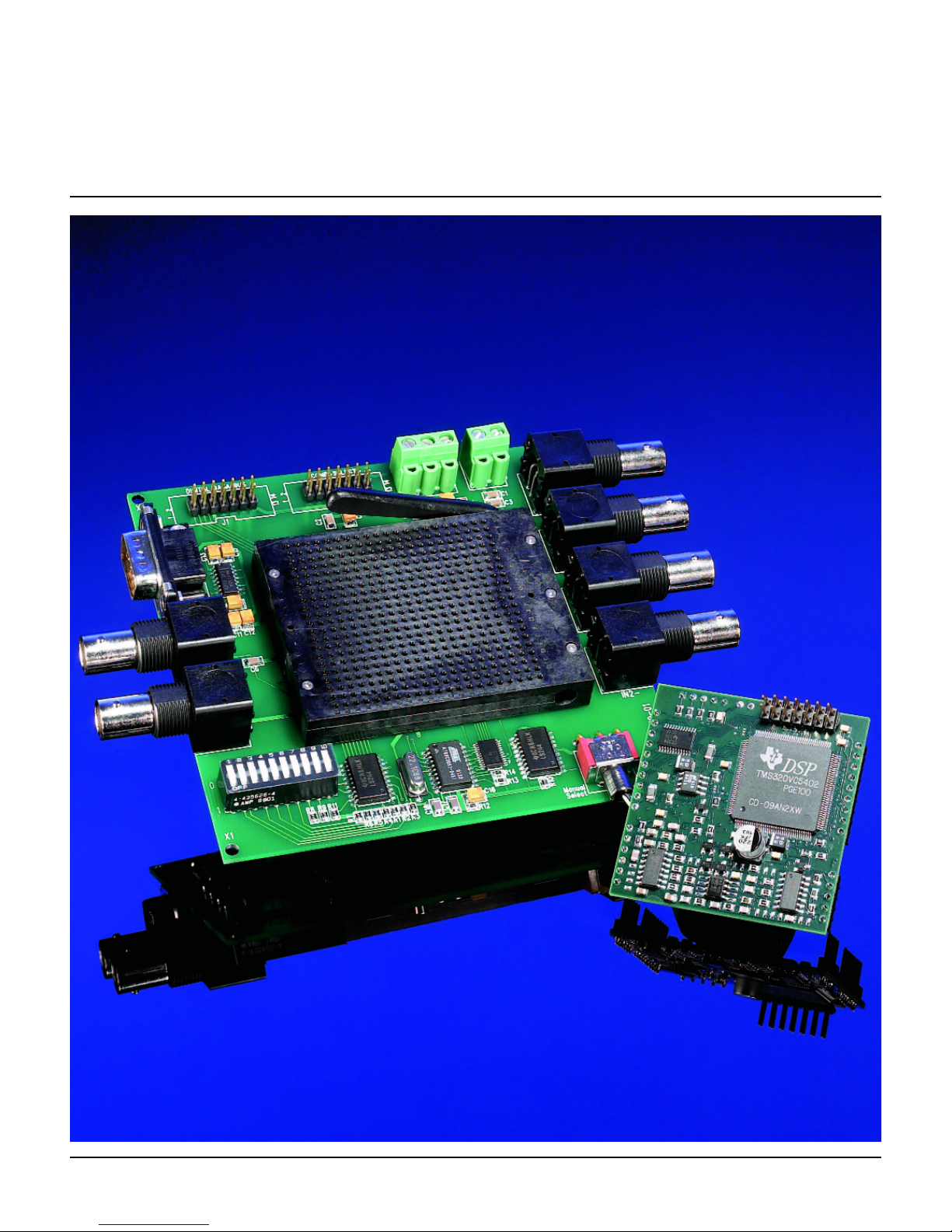
The SPPDF-01 is a FIR Filter Design Suite for the SPPDM-01 dual channel, FIR filter plat-
form with analog I/O that utilizes Frequency Devices MatLab
TM
GUI with MatLabTMV5.3 or
MatLab
TM
V6.0.
The SPPDF-01 Suite consists of:
• An SPPDM-01 dual channel signal processing platform containing a MatLabTMcompatible
FIR filter algorithm
• An SPPDB-01 development board for the SPPDM-01,
• An RS232, DB9 cable, and
• A CDRom with CDDF-01 software containing this manual, data sheets for the SPPDF-01,
SPPDM-01 and SPPDB-01, and the following utilities:
1. Filter Coefficient Generator (FCG) Software – This FCG software provides coeffi-
cient data conversion for FIR filters in the frequency domain and generates sets of
coefficients for single or multiple filters between 100 Hz and 20.0 kHz. From a set of
specifications, FCG produces a data set that approximates the given filter characteristics in the frequency domain. The FCG software is a tool compatible with MatLab
TM
V5.3 or MatLabTMV6.0 and allows the user to evaluate and modify low-pass, highpass, band-pass, and band-reject filters.
2. Filter Coefficient Loader (FCL) Software – FCL software is the communication and
translation interface that loads single or multiple sets of coefficients for various FIR filter types into the SPPDM-01 platform’s flash memory implementing the direct application, physical realization, and usage of the FIR filters. Coefficient loading utilizes the
RS232 interface on the SPPDB-01 development board to communicate with MatLab
TM
V5.3 or MatLabTMV6.0 FIR filter coefficient library files
Appendix C of this manual has information on how to add field programming capability. A circuit diagram is provided that may be added to the field application of the SPPDM-01
which emulates the SPPDB-01 development board and permits field loading of new filter
coefficient sets.
1.1 Hardware Description
The SPPDM-01 has a double precision FIR filter algorithm programmed into its EEPROM that
provides two channels of FIR filtering. Each channel is independently programmed and the FIR
algorithm can be configured, shaped or altered in terms of; corner frequency, number of taps
(shape factor) and filter type simply by loading different sets of coefficients. The FIR filter data
comes from a dual 24-bit sigma-delta ADC on the SPPDM-01. This 24-bit data is left-shifted to
automatically become a 32-bit double word. The on-board DSP reads a 32-bit coefficient set
from Flash Memory for each channel according to the user’s selection. Finally, the digital output
of the DSP is filtered and fed sequentially into a dual 24-bit DAC for conversion of the now filtered analog signals. The 2 Megabits Flash Memory permits many coefficient sets to be stored
and user addressed for maximum flexibility.
Many FIR filter types can be implemented with the DSP algorithm, provided the MatLab
TM
utili-
ty converges mathematically and the user stays within the 100 Hz to 20.0 kHz frequency range.
The number of filter channel taps for each filter channel must be ≤300.
25 Locust St, Haverhill, Massachusetts 01830 • Tel: 800/252-7074, 978/374-0761 • FAX: 978/521-1839
e-mail: sales@freqdev.com • Web Address: http://www.freqdev.com
SPPDF-01 Development Suite
User’s Manual
Introduction
Chapter I
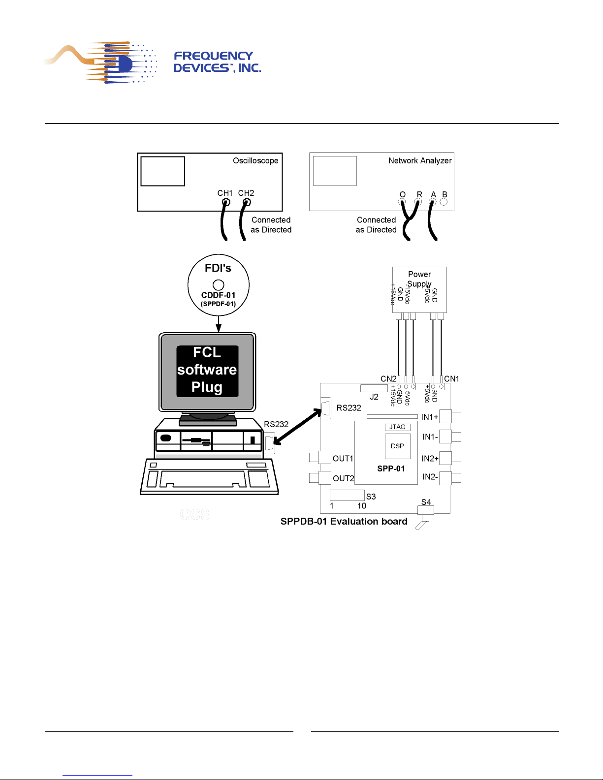
See Figure 1 for SPPDF-01 hardware configuration:
Figure 1 - SPPDF-01 Hardware Configuration
An oscilloscope is recommended for troubleshooting and a network analyzer is presented
as an example of a frequency-magnitude, frequency-phase signal characteristic analyzer.
4
DB9

25 Locust St, Haverhill, Massachusetts 01830 • Tel: 800/252-7074, 978/374-0761 • FAX: 978/521-1839
e-mail: sales@freqdev.com • Web Address: http://www.freqdev.com
SPPDF-01 Development Suite
User’s Manual
Introduction
Chapter I
1.2 Software Description
Users can define and configure filters using FREQUENCY DEVICES’ SPPDF-01 Filter
Coefficient Generator (FCG) software. The FCG - GUI is invoked from within the MatLab
TM
(User Supplied) environment and sends commands to the MatLabTMengine using the specific filter values loaded into the FCG – GUI. The MatLab
TM
engine responds to FCG commands and
calculates coefficient sets for the indicated FIR filters. These coefficient sets are temporarily
stored in the MatLab
TM
workspace environment. The filter response is displayed graphically with-
in MatLab
TM
for verification of program convergence and acceptability. To prevent loss, the coeffi-
cients sets can be stored as files on the PC in a designated folder, before exiting MatLab
TM
.
Note: the FCG software is provided as a convenience to the user. It is a tool to
facilitate standard FIR filter design. Experienced MatLab
TM
users may design their own
custom FIR filters for the SPPDM-01 using the appropriate MatLab
TM
FIR design tools, as
long as SPPDF-01 design constraints are met.
Design constraints on the SPPDM-01 FIR Filter Platform are:
• Frequency Range: 100 Hz to 20 kHz
• Maximum Number of Taps: 300.
Note: Low-pass and high-pass filters are easily configured but some versions of bandpass and band-reject filters might not converge mathematically within some of the constraints. User may be required to try other parameter combinations until a converging
implementation is found.
Chapter II of this document will be directed to MatLab
TM
users who wish to use Frequency
Devices’ FCG-GUI to design standard FIR filters for the SPPDM-01. The experienced MatLab
TM
filter designer may skip Chapter II and go right to Chapter III, the Filter Coefficient Loader (FCL)
section.
The FCG software is a design tool for FIR filters to be used within the MatLabTMenviron-
ment. The FCG software provides for the entry of specific filter parameters into the MatLab
TM
environment allowing the MatLabTMengine to calculate coefficients that approximate the given filter descriptions.
User must first determine filter type, followed by selection of various specification parame-
ters. Based on the selected values, MatLab
TM
creates a best approximation set of coefficients.
This set of coefficients corresponds to a single or multiple number of filters and may be managed
in two modes: Immediate and Batch.
• Immediate Mode of operation relies on the MatLab
TM
workspace to present the set of
coefficients as an M x N matrix where M is the number of filters and N is the number
of coefficients for each filter. See Appendix A - Examples 2 and 3.
• Batch Mode of operation creates a text batch file where the system saves the set
of coefficients uniquely identified by the various filters. See Appendix A – Examples
4 and 5.
5
25 Locust St, Haverhill, Massachusetts 01830 • Tel: 800/252-7074, 978/374-0761 • FAX: 978/521-1839
e-mail: sales@freqdev.com • Web Address: http://www.freqdev.com
SPPDF-01 Development Suite
User’s Manual
Filter Coefficient Generator
Chapter II
2.1. FCG Installation and Startup:
Install the FCG software by inserting the CDDF-01 disk into the PC, CDRom drive.
Select the drive in Explorer or use the RUN menu.
CLICK on the Filter Coefficient Generator folder, then
CLICK on "SETUP" and follow the instructions on the installation window.
After installation of the software, two shortcuts will be inserted on the desktop, namely
FCG and FCGScript. Configure the software to run under the installed version of MatLab
TM
by
running the FCGConfig file located under the FCG directory, Program Files in the Windows directory. The FCGConfig program will ask and set the location of your MatLab
TM
engine file:
matlab.exe.
After configuring the environment, DOUBLE CLICK on the new short cut called FCG on
the PC desktop to start the program.
The experienced user may skip the above steps by loading the MatLab
TM
environment,
going to the specific directories, and making the necessary initializations and M-file calls from
within MatLab
TM
. This will automatically invoke the FCG main panel GUI.
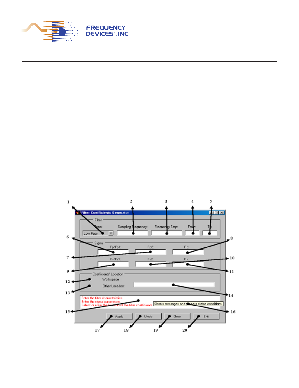
2.2 FCG GUI Control Group Descriptions
The components of the main panel are shown in the Figure 2 below:
Figure 2 – Filter Coefficient Generator Main Panel
6

25 Locust St, Haverhill, Massachusetts 01830 • Tel: 800/252-7074, 978/374-0761 • FAX: 978/521-1839
e-mail: sales@freqdev.com • Web Address: http://www.freqdev.com
SPPDF-01 Development Suite
User’s Manual
Filter Coefficient Generator
Chapter II
The main panel GUI is divided into five functional groups. Note: All entries or selections must
be completed in all groups before the "Apply" command (which initiates the filter coefficient generation) is executed.
2.2.1 Group A, Filter (Items 1 - 5) - contain the controls necessary to specify the parameters
used in the generation of sets of coefficients for single or multiple filters over a predefined
bandwidth.
1. Filter Type List Control: Is used to select filter type. Select Low-Pass, High-Pass,
Band-Pass or Band-Stop. The default value shown at startup is Low-Pass. When
selecting Low-Pass or High-Pass Filter Type, the Second Pass-band Cutoff Input
Control (Fp2) and the Second Stop-band Cutoff Input Control (Fs2) will be disabled.
2. Sampling Frequency Input Control: Specifies the sampling frequency. Sampling frequency must be entered. Required sampling rate for the SPPDM-01 family of prod-
ucts is always 48000Hz.
3. Frequency Step Input Control: Enters a constant that represents the frequency steps
for the generation of the sets of filter coefficients over the bandwidth for a particular filter. Since there is a limit to the maximum number of steps, small step sizes may limit
bandwidth. The Frequency Step (Fstep) represents a positive number limited by
SPPDM-01 family parameters such as the Maximum Bandwidth (MB) (100 to 20,000
Hz) and the Maximum Number of Filters (MNF = 512). For a specific filter, the Per Step
Maximum Number of Filters (PSMNF) is calculated to be PSMNF = MB / Fstep. This
value must be greater than one and less than MNF. The frequency step value is meaningless when only one set of filter coefficients is generated. A valid Fstep must be
entered.
4. From: Range Input Control is used to enter a numeric value for the lowest bandwidth
limit. It represents the starting point in the generation of the sets of filter coefficients.
The “To” (Item 5) is enabled when a valid number is entered into From. The number
must be between 1 and the MNF of 512.
5. To: Range Input Control enters a numeric value for the highest bandwidth limit. It represents the end point used in the generation of the sets of filter coefficients. The number must be between 1 and 512 for the frequency step. The number must be equal or
greater than the “From” number (Item 4). This control remains disabled until a valid
From value is entered. Then a valid To value can be entered.
2.2.2 Group B, Signal (Items 6 - 11) - are the controls used to input the relative specifications
for the filter(s) described in Group A.
6. Fp/Fp1: First Pass-band Cutoff Input Control enters a numeric value interpreted as
Pass-band Cutoff Frequency (Fp in Hz) for low-pass and high-pass type filters and as
First Pass-band Cutoff (Fp1) frequency for band-pass and band-stop type filters.
7. Fp2: Second Pass-band Cutoff Input Control enters a numeric value interpreted as
Second Pass-band Cutoff Frequency (Fp2 in Hz) for band-pass and band-stop type filters. This control is enabled only when the Filter Type (Item 1, Figure 1) selected is
either Band-Pass or Band-Stop.
7

25 Locust St, Haverhill, Massachusetts 01830 • Tel: 800/252-7074, 978/374-0761 • FAX: 978/521-1839
e-mail: sales@freqdev.com • Web Address: http://www.freqdev.com
SPPDF-01 Development Suite
User’s Manual
Filter Coefficient Generator
Chapter II
8. Rp: Pass-band Ripple Input Control enters a numeric value interpreted as the Pass-
band Ripple (Rp in dB) for every type of filter selected. When entering values, a good
ripple value is one that produces convergence in the FIR coefficient generation algorithms when combined with the other relative specifications. Common values of ripple
for convergence are from 0.01 to 0.1 dB.
9. Fs/Fs1: First Stop-band Cutoff Input Control enters a numeric value interpreted as
Stop-band Cutoff Frequency (Fs in Hz) for low-pass and high-pass type filters and as
First Stop-band Cutoff Frequency (Fs1) for band-pass and band-stop type of filters.
10. Fs2: Second Stop-band Cutoff Input Control enters a numeric value interpreted as
Second Stop-band Cutoff Frequency (Fs2 in Hz) for band-pass and band-stop type of
filters. This control is enabled only when the Filter Type (Item 1, Figure 1) selected is
either Band Pass or Band Stop.
11. Rs: Stop-band Attenuation Input Control enters a numeric value interpreted as the
Stop-band Attenuation (Rs in dB) for every type of filter selected. The stop-band attenuation must be less than or equal to the maximum bandwidth. Valid stop-band atten-
uation must be entered.
2.2.3 Group C, Coefficient Location (Items 12 - 14) - manages the two available modes of
operation: Immediate mode and Batch mode.
12. Workspace: CLICK this button whenever the set/sets of filter coefficients are to be
dumped into the MatLab
TM
Workspace. This provides immediate access of the coeffi-
cients through a matrix data structure in the workspace. User may want to initialize an
Mx Nmatrix variable that will contain the coefficient data where M is the number of filters and N is the number of coefficients per filter. Note: data will be lost if the work-
space is cleared, or in quitting the MatLab
TM
environment without saving the vari-
able contents.
13. Other Location: CLICK this button whenever the set/sets of filter coefficients are to be
down loaded to a specific text file. This provides access to the coefficients at a later
time. For example, the file may be accessed and its contents read into a matrix structure in the workspace. The inexperienced user should use this mode of operation
when attempting to use the FCG - FGL setup. The experienced user may accomplish
every task from within MatLab
TM
, allowing the use of the systems in immediate mode.
Selecting this control enables the Batch Mode Input Control Window next to the
Other Location button.
14. Batch Mode Input Control Window: This window is enabled whenever the Other
Location button is selected. This window allows entry of files from any other location
different from the MatLab
TM
workspace. Complete pathname must be entered for the
file destination. The name of the file must have the ".coe" suffix, otherwise it will
not be validated. The file created will identify each set of coefficients using the following format: filt1 tab-character coefficient1 tab-character coefficient2 tab-character …
coefficientN newline filt2 …
8

25 Locust St, Haverhill, Massachusetts 01830 • Tel: 800/252-7074, 978/374-0761 • FAX: 978/521-1839
e-mail: sales@freqdev.com • Web Address: http://www.freqdev.com
SPPDF-01 Development Suite
User’s Manual
Filter Coefficient Generator
Chapter II
2.2.4 Group D, Message (Items 15 - 16) - contains an indicator that shows system status, and
generation process information at specific instances. This group also presents controls’
(tooltips) about functional characteristics.
15.Message Text Box Window: This window continuously shows messages and process
status conditions. It provides next step usage indications to help user/system interaction.
It serves as a tool to obtain information about the system status and the coefficients generation process.
16.Tooltip Indicator: Placing the cursor over any message or status line in the window, will
produce a drop down text with an explanation. To obtain next step; process instructions,
controls, indicator purpose, functions, or descriptions, place cursor over any control or
indicator in the FCG panel. This tool is used to learn about a control or indicator function
before its use.
2.2.5 Group E, Command (Items 17 - 20) - allows the user to initiate certain process/system
commands.
17. Apply: Using this command button starts the filter generation process using the entered
group of parameters. It also initiates plots of filter amplitude and phase for each set of
coefficients generated. The command enables execution only after appropriate parameters have been entered and validated. After completion, it sends the coefficients to the
location specified in the Coefficients’ Location Group (Group C, Items 12, 13 and 14).
18. "Undo" & 19. "Clear" Command Buttons: These command buttons are "dummy" but-
tons. They are for features yet to be implemented. They are provided as tools for an
experienced programmer who wishes to add commands to start a specific sequence of
instructions. Their default function is to present a message to the user.
20. Exit: Use this command button to exit the software. It closes any open windows and
quits the FCG system. The MatLab
TM
environment may continue to be used after exiting
the FCG software.
9

25 Locust St, Haverhill, Massachusetts 01830 • Tel: 800/252-7074, 978/374-0761 • FAX: 978/521-1839
e-mail: sales@freqdev.com • Web Address: http://www.freqdev.com
SPPDF-01 Development Suite
User’s Manual
Filter Coefficient Loader
Chapter III
The Filter Coefficients Loader (FCL) Software is a tool that performs the interface, com-
munication, translation, and formatting functions for single or multiple sets of coefficients and different filter types for loading into an SPPDM-01 platform using the SPPDB-01 development
board. The FCL also reformats and initiates the translation of FIR filter coefficient data into a format that is recognized by the SPPDM-01 hardware as coefficients that influence the imbedded
FIR filter algorithm.
FCL allows the user to issue a single command to select and load mode of operation, serial communication parameters, and filter addresses in memory space. The user starts the
process that implements the SPPDB-01, RS232 serial communication port, using a translationformatter to transform the "raw" coefficient data into FIR specifications recognized by the
SPPDM-01 FIR filter algorithm. For this to occur, the FCL uses a "software plug" (see Appendix
B) that groups a set of dynamically linked subroutines for translation formatting of coefficient data
into a recognizable pattern of information. It also uses a graphical user interface that implements
a serial communication protocol for the loading of coefficients into the SPPDM-01.
The FCL’s role in FIR design and application is to provide the means for the filter coefficients generated, from relative specifications, to be interpreted as valid frequency-magnitude/frequency-phase characteristics by the SPPDM-01. This allows performance of real time analysis,
experiments, decision-making, etc. in an easy, fast, reliable and repeatable way.
3.1 Equipment Required:
Provided by Frequency Devices
3.1.1 SPPDF-01 FIR Filter Development Suite
• SPPDM-01 FIR filter platform
• SPPDB-01 Design/Development Board
3.1.2 Filter Coefficients Generator and Loader Software Installation Disk, CDDF-01
3.1.3 RS232 cable and connectors, provided with SPPDF-01
Provided by Customer
3.1.4 PC Test Station (Windows 9x or more) MatLabTMV5.3 or higher
3.1.5 ±15Vdc, +5Vdc Power Supply
3.2 Installation and Startup:
To install the FCL software, insert the CDDF-01 disk provided with the Development Suite
in the appropriate CDRom drive.
• Select the Filter Coefficient Loader folder
• RUN setup and follow instructions on the installation window.
10

25 Locust St, Haverhill, Massachusetts 01830 • Tel: 800/252-7074, 978/374-0761 • FAX: 978/521-1839
e-mail: sales@freqdev.com • Web Address: http://www.freqdev.com
SPPDF-01 Development Suite
User’s Manual
Filter Coefficient Loader
Chapter III
After installation of the software, two shortcuts are inserted on the desktop, namely FCL
and FCLScript. The software must be configured to run under the installed version of MatLab
TM
by running the FCLConfig file located under the FCG directory Program Files in the Windows
directory. The FCLConfig program will ask and set the location of the MatLab
TM
engine file: matlab.exe. After configuring the environment, DOUBLE CLICK on the new short cut called FCL on
the PC desktop to start the program.
The experienced user may skip the above steps by loading the MatLab
TM
environment,
going to the specific directories, and making the necessary initializations and M-file calls from
within MatLab
TM
. This will automatically invoke the FCL main panel GUI.
3.3 FCL GUI Main Panel:
The components of the FCL, GUI Main Panel are shown in the Figure 3 below:
Figure 3 - Filter Coefficient Loader GUI Main Panel
The main panel is divided into five functional groups. Note: All entries or selections
must be completed in all groups before the "Program" command (Item 18) is executed.
3.3.1 Group A, Filter (Items 1 - 5) - contains the controls necessary to specify the
parameters used for loading sets of coefficients for single or multiple filters over a
predefined bandwidth.
11

25 Locust St, Haverhill, Massachusetts 01830 • Tel: 800/252-7074, 978/374-0761 • FAX: 978/521-1839
e-mail: sales@freqdev.com • Web Address: http://www.freqdev.com
SPPDF-01 Development Suite
User’s Manual
Filter Coefficient Loader
Chapter III
1. Filter Number: CLICK on this control whenever a single set of coefficients is to be loaded
into the SPPDM-01 external memory. Selecting this control enables the Filter Number
Input Control Window (Item 2).
2. Filter Number Input Control Window: This control is enabled whenever the Filter
Number Selector is used. This control allows entry of the numeric value that identifies a
single set of coefficients as the taps for a specific filter. The number must be between 1
and 512, the maximum number of filters (MNF) allowed.
3. Filter Range: CLICK on this control whenever multiple sets of coefficients need to be
loaded into the SPPDM-01 external memory. Selecting this control enables the Filter
Range (From) Input Control (Item 4).
4. Filter Range (From) Input Control: This control is enabled whenever the Filter Range is
selected. With this control the user enters a numeric value representing the lowest filter
identification number to load. It represents the starting point identifying the multiple sets
of coefficients as the taps for a specific group of sequentially positioned filters. The number must be between 1 and 512, the MNF allowed.
5. Filter Range (To) Indicator: This indicator shows a numeric value representing the highest filter identification number LOADED. It represents the end point, identifying the multiple sets of coefficients as the taps for a specific group of sequentially positioned filters.
The number must be between 1 and 512, the MNF allowed. The Filter Range (To)
number must be equal or greater than the Filter Range (From) number.
3.3.2 Group B, Coefficients’ Location (Items 6 - 7): Manages the immediate and batch modes
of operation.
6. Workspace: CLICK on the "Workspace" button to enable the Immediate Mode. This
allows the set or sets of filter coefficients to be loaded from the MatLab
TM
Workspace and
immediately accesses the coefficients through a matrix data structure (See Chapter II,
Item 12). The FCG software may produce the matrix data. Note: Data is lost 1) if the
workspace is cleared, or 2) quitting the MatLab
TM
environment without saving the
variable contents.
7. Other Location: CLICK the "Other Location" button to enable the Batch Mode window.
This will allow a set or sets of filter coefficients to be loaded from a specific text file into
the SPPDM-01. Selecting this control enables the Batch Mode Input Control Window
(Item 8).
8. Batch Mode Input Control: This control window becomes active whenever the Batch
Mode Selector "Other Location" is selected. Use this window to enter any other location
different from the MatLab
TM
workspace. The complete path-name for the file destination
must be entered. The name of the file must have the ".coe" suffix, otherwise it will
not be validated. The workspace variable created specifies the set of coefficients as an M
x N matrix. Variable M is the number of filters and N is the number of coefficients per filter.
3.3.3 Group C, Serial Communication (Items 9 – 15): presents the controls used to set and
enter the parameters that control the serial communication protocol.
12

25 Locust St, Haverhill, Massachusetts 01830 • Tel: 800/252-7074, 978/374-0761 • FAX: 978/521-1839
e-mail: sales@freqdev.com • Web Address: http://www.freqdev.com
SPPDF-01 Development Suite
User’s Manual
Filter Coefficient Loader
Chapter III
9. Port: Use this control to select the communication port through which data will flow.
Select a number starting from 1 for the communication port one up to 32 for the communication port thirty-two. The selection must be made before the loading of coefficients is
started. The default value shown at startup is 1. See the operating system’s manuals for
the PC for instructions on how to configure higher number ports.
10. Parity: Use this control to select the parity mode for the selected communication port.
For the SPPDF-01 parity must be "None". Select None for no parity,
11. Data: Use this control to select the number of data bits for the selected communication
port. For the SPPDF-01 the data (bits) must be set to "8".
12. Stop: Use this control to select the number of stop bits for the selected communication
port. For the SPP environment the stop (bits) must be "1".
13. Baud Rate: Use this control to select the baud rate for the selected communication port.
For the SPPDF-01 environment the baud rate must be set to "9600".
14. Out Buffer Size: Use this control to enter a numeric value that specifies the size of the
output queue for the selected communication port. This number is not limited to a specific
range of values. A valid output buffer size value must be entered before the loading
of coefficients. Default is 512 bytes.
15. In Buffer Size: This control enters a numeric value that specifies the size of the input
queue for the selected communication port. This number is not limited to a specific range
of values. A valid input buffer size value must be entered before the loading of coefficients. Default is 512 bytes.
3.3.4 Group D, Message Group (Items 16 – 18): contains an indicator that shows system sta-
tus, and generation process information for specific cases. This group also presents controls’ (tooltips) about functional characteristics and a progress bar for relative process
completion at specific instances.
16. Message Text Box: This window continuously shows messages and process status conditions. It presents next step usage messages to aid with user-system interaction. It
serves as a tool to obtain sequential information about the system status and coefficient
loading process.
17. Tooltip Indicator: Position the cursor on top of a status line or message in the status window to obtain next step process instructions in a drop down text box. Putting the cursor
over any control or indicator in the FCL, GUI panel provides a short description of that
control. Use this tool to learn about the control or indicator function before it is used.
3.3.5 Group E, Command Group (Items 18 – 21): allows the user to initiate certain
process/system commands.
18. Program Command Button: This command button starts the filter set/sets of coefficient
loading process utilizing the selected parameters. This starts the translation, formatting
and loading process through the "software plug (Appendix B)". After successful completion, the coefficients will reside in the SPPDM-01 external memory. This command will
only execute after all required parameters have been entered and validated.
13

25 Locust St, Haverhill, Massachusetts 01830 • Tel: 800/252-7074, 978/374-0761 • FAX: 978/521-1839
e-mail: sales@freqdev.com • Web Address: http://www.freqdev.com
SPPDF-01 Development Suite
User’s Manual
Filter Coefficient Loader
Chapter III
19. "Verify" & 20. "Erase": These command buttons are "dummy" buttons. They are for
features yet to be implemented. They are provided as tools for the experienced programmer who wishes to add commands to start a specific sequence of instructions.
Their default function is to present a message to the user.
21. Exit: Use this command button to exit the software. It closes any open panels and quits
the FCL system. The MatLab
TM
environment may continue to be used after exiting.
14

25 Locust St, Haverhill, Massachusetts 01830 • Tel: 800/252-7074, 978/374-0761 • FAX: 978/521-1839
e-mail: sales@freqdev.com • Web Address: http://www.freqdev.com
SPPDF-01 Development Suite
User’s Manual
SPPDB-01
Manual FIR Filter Selection
Appendix A - Example 1
For Manual FIR Filter Selection a 10-bit DIP-switch on the SPPDB-01 is used to select a
filter to run for each SPPDM-01 channel. It is designated as D
0
to D9, where D9is the most sig-
nificant bit (MSB), while D
0
is the least significant bit (LSB). In the SPPDF-01 Suite, D9is used
as a channel selection bit (Channel 1 (0) and Channel 2 (1)). D
0
to D8are used as frequency
selection bits. The DSP checks the switch status at the rate of 48 kHz. If the status has
changed, the DSP follows these steps:
• Check D
9
bit. If D9is ‘0’, the filter number selection is set for channel one (1), if D9is
‘1’, the filter number selection is set for channel two (2).
• Extract bits D
0
to D8and get the filter setting number.
• According to the filter number, calculate the coefficient set address in flash memory.
• Copy the coefficient set into the DSP internal memory.
• Run with new coefficients.
With 9-bit tuning (D
0
thru D8), up to 512 different filter numbers (coefficients) can be
selected for each channel on SPPDM-01. Although the FCG can create 1 to 682 sets of filter
coefficients at one time, only the first 512 sets are accessible. To select a filter number, set D
0
to
D
8
according to the following formula.
FN=1+D
0+D1
*2+D2*4+D3*8+D4*16+D5*32+D6*64+D7*128+D8*256. Where FN means Filter
Number.
15

25 Locust St, Haverhill, Massachusetts 01830 • Tel: 800/252-7074, 978/374-0761 • FAX: 978/521-1839
e-mail: sales@freqdev.com • Web Address: http://www.freqdev.com
SPPDF-01 Development Suite
User’s Manual
FCG Immediate Mode Operation
Single Set Coefficient
Appendix A - Example 2
1. Open MatLabTMand initialize a global variable in the MatLabTMworkspace called coeffi-
cients. Set the format to long for better representation of the results.
Figure 4 – Filter Coefficient Generator Display,
Immediate Mode Operation - Single Coefficient Set
2. Initiate the FCG by clicking on the desktop icon. On the GUI, under "Filter Type"
select Low Pass as the filter. Notice that the Second Pass-band Cutoff Input Control and
the Second Stop-band Cutoff Input Control are disabled and no longer visible.
3. Sampling Frequency: Enter 48000 (Hertz) as the sampling frequency. This value is con-
stant for the SPPDM-01 family of products. Remember to drop units (Hertz) when entering this and the following parameters
4. Frequency Step: Enter 100 as the frequency increment between sets of coefficients.
5. From: - Enter the (Range) From Value: Enter 1 as the lowest filter number.
6. To: - Enter the (Range) To Value: Enter 1 as the highest filter number. This will generate
only one set of filter coefficients for the type selected. This also makes the Frequency
Step value meaningless.
7. Fp/Fp1 - Enter the Pass-band Cutoff Frequency: Enter 10300 (Hertz) as the pass-band
cutoff frequency.
8. Rp - Enter the Pass-band Ripple: Enter 0.01 (dB) as the pass-band ripple.
16

25 Locust St, Haverhill, Massachusetts 01830 • Tel: 800/252-7074, 978/374-0761 • FAX: 978/521-1839
e-mail: sales@freqdev.com • Web Address: http://www.freqdev.com
SPPDF-01 Development Suite
User’s Manual
FCG Immediate Mode Operation
Single Set Coefficient
Appendix A - Example 2
9. Fs/Fs1 - Enter the Stop-band Cutoff Frequency: Enter 11050 (Hertz) as the stop-band
cutoff frequency.
10. Rs - Enter the Stop-band Attenuation: Enter 98.5 (dB) as the Stop band Attenuation.
Drop the negative sign when entering this parameter.
11. Select MatLab
TM
Workspace: CLICK on the workspace location control for immediate
mode of coefficients generation.
12. Generate the Coefficients: CLICK on Apply to start the immediate mode of coefficients
generation process and send the set of coefficients to the MatLab
TM
workspace. This also
starts the Amplitude/Phase Plot shown in Figure 5 below:
Figure 5 - Amplitude/Phase Plot – Immediate Mode Operation, Single
12.1. Frequency-Magnitude (Hz-dB) Characteristics Plot: Shows the frequency-mag-
nitude characteristics graph for the set of coefficients generated for the filter and
allows design decisions to be made for actual FIR filters designed from the set of
entered parameters.
12.2. Frequency-Phase (Hz-degrees) Characteristics Plot: Presents the frequency-
phase characteristics plot representation for the entered set of filter coefficients.
The graph shows the user the ideal frequency-phase representation.
17

25 Locust St, Haverhill, Massachusetts 01830 • Tel: 800/252-7074, 978/374-0761 • FAX: 978/521-1839
e-mail: sales@freqdev.com • Web Address: http://www.freqdev.com
SPPDF-01 Development Suite
User’s Manual
FCG Immediate Mode Operation
Single Set Coefficient
Appendix A - Example 2
12.3. Go Command Button: CLICK Go and the plot panel window will close and execu-
tion will return to the main panel.
12.4. Stop Command Button: CLICKING Stop will close the plot panel window and
return user to the main panel.
13. Note: CLICK Go command button after inspecting the amplitude/phase characteristics
representations to close the plot panel window and return to the main panel. You may
also CLICK the Stop command button to get to the main panel. The Message indicator
shows the number of filters designed. For this example it is one (1).
14. Inspect results: At the MatLab
TM
environment prompt type: whos. The system will
respond with the information for the coefficients variable:
Name Size Bytes Class
coefficients 1x299 2392 double array (global)
Grand total is 299 elements using 2392 bytes
IMPORTANT
Remember: When clearing or quitting the workspace, the coefficients data will be
lost unless the variables are saved to the workspace. After saving them, the coefficients may be used as desired: i.e. loading into the SPPDM-01 platform, mathematical transformation, inspection, etc. Follow MatLab
TM
’s and the FCL’s instructions for
performing these tasks.
References:
1.1. The Mathworks, Using MatLab
TM
Graphics
1.2. The Mathworks, Building GUI’s with MatLab
TM
1.3. The Mathworks, Using MatLab
TM
1.4. The Mathworks, MatLabTMFunction Reference
1.5. The Mathworks, Application Program Interface (API) Guide
1.6. The Mathworks, Application Program Interface (API) Reference
1.7. SPPDF-01 Operation/User Manual
SPPDB-01 Specifications Sheets
18

25 Locust St, Haverhill, Massachusetts 01830 • Tel: 800/252-7074, 978/374-0761 • FAX: 978/521-1839
e-mail: sales@freqdev.com • Web Address: http://www.freqdev.com
SPPDF-01 Development Suite
User’s Manual
FCG Immediate Mode Operation
Multiple Coefficient Sets
Appendix A - Example 3
1. Open MatLabTMand load into the initialize a global variable in the MatLabTMworkspace
called coefficients. Set the format to long for better representation of the results. Initialize
this variable by loading the values obtained from the FCG software or any other coefficient
generating software. The experienced user may find it easier to work within the MatLab
TM
environment with both, FCG and FCL, without quitting MatLabTM.
Figure 6 – Filter Coefficient Generator Display,
Immediate Mode Operation – Multiple Coefficient Sets
2. Initiate the FCL by clicking on the desktop icon. On the GUI, under "Filter Type"
select Low Pass as the filter. Notice that the Second Pass-band Cutoff Input Control and
the Second Stop-band Cutoff Input Control are disabled and no longer visible. An experienced user may continue to use MatLab
TM
if already opened, by starting the M-file that ini-
tialized the FCL-GUI.
3. Sampling Frequency: Enter 48000 (Hertz) as the sampling frequency. This value is con-
stant for the SPPDM-01 family of products. Remember to drop units (Hertz) when entering this and the following parameters
4. Frequency Step: Enter 1000 as the frequency increment between sets of coefficients.
5. From: - Enter the (Range) From Value: Enter 1 as the lowest filter number.
6. To: - Enter the (Range) To Value: Enter 5 as the highest filter number. This will generate
five (5) sets of filter coefficients for the type selected. The sets are created in steps specified in the Frequency Step control.
7. Fp/Fp1 - Enter the Pass-band Cutoff Frequency: Enter 10300 (Hertz) as the pass-band
cutoff frequency. 8. Rp - Enter the Pass-band Ripple: Enter 0.01 (dB) as the pass-band
ripple.
19

25 Locust St, Haverhill, Massachusetts 01830 • Tel: 800/252-7074, 978/374-0761 • FAX: 978/521-1839
e-mail: sales@freqdev.com • Web Address: http://www.freqdev.com
SPPDF-01 Development Suite
User’s Manual
FCG Immediate Mode Operation
Multiple Coefficient Sets
Appendix A - Example 3
8. Rp - Enter the Pass-band Ripple: Enter 0.01 (dB) as the pass-band ripple.
9. Fs/Fs1 - Enter the Stop-band Cutoff Frequency: Enter 11050 (Hertz) as the stop-band
cutoff frequency.
10. Rs - Enter the Stop-band Attenuation: Enter 98.5 (dB) as the Stop-band Attenuation.
Drop the negative sign when entering this parameter.
11. Select MatLab
TM
Workspace: CLICK on the workspace location control for immediate
mode of coefficients generation.
12. Generate the Coefficients: CLICK on Apply to start the immediate mode of coefficients
generation process and send the set of coefficients to the MatLab
TM
workspace. This also
starts the Amplitude/Phase Plot shown in Figure 7 below:
Figure 7 - Amplitude/Phase Plot – Immediate Mode Operation
(First plot in a multiple number of plots)
13. Go: CLICK the Go command button after inspecting the amplitude/phase characteristics,
to close the plot panel window and return to the main panel. The Stop command button
may also be clicked to return to the main panel. The Message indicator shows the number of filters designed.
20

25 Locust St, Haverhill, Massachusetts 01830 • Tel: 800/252-7074, 978/374-0761 • FAX: 978/521-1839
e-mail: sales@freqdev.com • Web Address: http://www.freqdev.com
SPPDF-01 Development Suite
User’s Manual
FCG Immediate Mode Operation
Multiple Coefficient Sets
Appendix A - Example 3
14. Inspect results: At the MatLabTMenvironment prompt, type: whos. The system will
respond with the information for the coefficients variable:
Name Size Bytes Class
coefficients 5x299 11960 double array (global)
Grand total is 1495 elements using 1
1960 bytes
IMPORTANT
Remember that, when clearing or quitting the workspace, the coefficients data will be lost
unless the variables are saved to the workspace. After saving them, the coefficients may
be used as desired: i.e. loading into the SPPDM-01 platform, mathematical transformation, inspection, etc. Follow MatLab
TM
’s and the FCL’s instructions for performing these
tasks.
References:
1.1. The Mathworks, Using MatLab
TM
Graphics
1.2. The Mathworks, Building GUI’s with MatLab
TM
1.3. The Mathworks, Using MatLab
TM
1.4. The Mathworks, MatLabTM Function Reference
1.5. The Mathworks, Application Program Interface (API) Guide
1.6. The Mathworks, Application Program Interface (API) Reference
1.7. SPPDF-01 Operation/User Manual
1.8. SPPDB-01 Specifications Sheets
21

25 Locust St, Haverhill, Massachusetts 01830 • Tel: 800/252-7074, 978/374-0761 • FAX: 978/521-1839
e-mail: sales@freqdev.com • Web Address: http://www.freqdev.com
SPPDF-01 Development Suite
User’s Manual
FCL Batch Mode Operation
Single Set Coefficient
Appendix A - Example 4
1. Initialize a global variable in the MatLabTMworkspace called coefficients. Set the format
to long for better representation of the results.
Figure 8 – FCL Display, Single Set Coefficient, Batch Mode Operation
2. Select Filter Number: CLICK on the Filter Number control for loading of a single set of
coefficients.
3. Enter the Filter Number: Enter 10 to identify the filter and specify its location in memory
as the tenth one.
4. Select MatLab
TM
Workspace: CLICK on the workspace location control to load the coeffi-
cients directly from the workspace.
5. Select the communication port: Select 2 as the communication port.
6. Select the Parity: Select None as the parity for the selected communication port. This
value is constant for the SPPDM-01 family of products.
7. Select the Data (Bits) Number: Select 8 as the number of data bits for the selected com-
munication port. This value is constant for the SPPDM-01 family of products.
8. Select the Stop (Bits) Number: Select 1 as the number of stop bits for the selected com-
munication port. This value is constant for the SPPDM-01 family of products.
9. Select the Baud Rate: Select 9600 as the baud rate for the selected communication port.
This value is constant for the SPPDM-01 family of products.
10. Enter the Out(put) Buffer Size: Enter 512 (bytes) as the size of the output buffer for the
selected communication port. Remember to drop the units when entering this parameter.
22

25 Locust St, Haverhill, Massachusetts 01830 • Tel: 800/252-7074, 978/374-0761 • FAX: 978/521-1839
e-mail: sales@freqdev.com • Web Address: http://www.freqdev.com
SPPDF-01 Development Suite
User’s Manual
FCL Batch Mode Operation
Single Set Coefficient
Appendix A - Example 4
11. Enter the In(put) Buffer Size: Enter 512 (bytes) as the size of the input buffer for the
selected communication port. Remember to drop the units when entering this parameter.
12. Load the single set of Coefficients: CLICK Program to start the loading process of the
single set of coefficients from the workspace into the SPPDM-01’s external memory location. A popup window with a bar will indicate an active system condition. After a few seconds of data translating and formatting, the Software Plug (Appendix B) takes over and
starts the communication protocol.
Wait for the communication protocol process to finish. After successful completion of the
loading process, the workspace will show successful memory verification. The Message
indicator will show the number of filters loaded. For this example it is one (1).
13. Inspect results: At the MatLab
TM
environment prompt type: whos. The system will
respond with the information for the coefficients variable:
Name Size Bytes Class
coefficients 1x320 2560 double array (global)
Grand total is 320 elements using 2560bytes
14. User can work with the coefficients as desired. For example: Load them into an SPPDM-
01, mathematically transform them, inspect them, etc. Remember - If the workspace is
cleared or exited, the coefficient data is lost unless the variables or the workspace are
saved. Follow MatLab
TM
instructions for performing these tasks.
15. Reboot the SPPDM-01 unit: Turn the power to the SPPDB-01 evaluation board OFF.
When the unit is turned ON, the last entered set of coefficients is loaded from the
SPPDM-01’s external memory into the DSP internal memory where it is interpreted as
valid FIR filter characteristics in the frequency domain.
16. Inspect or work with the SPPDM-01’s FIR filter: The filter may now be selected in
Manual Mode Operation, Appendix A - Example 1 (with DIP switches), or automatically
(with a computer program). Select the filter by setting the selection code to the desired filter location (number). This will set the SPPDB-01 evaluation board and the SPPDM-01 to
work as a FIR filter possessing the frequency domain characteristics derived from the initial relative specifications.
23

25 Locust St, Haverhill, Massachusetts 01830 • Tel: 800/252-7074, 978/374-0761 • FAX: 978/521-1839
e-mail: sales@freqdev.com • Web Address: http://www.freqdev.com
SPPDF-01 Development Suite
User’s Manual
FCL Batch Mode Operation
Single Set Coefficient
Appendix A - Example 5
1. Initialize a global variable in the MatLabTMworkspace called coefficients. Set the format
to long for better representation of the results.
Figure 9 -
FCL Display – Batch Mode Operation, Multiple Set Coefficients
2. Select Filter Range: CLICK on the Filter Range control. This will allow you to load a
multiple set of coefficients.
3. Enter the Filter Range (From) Value: Enter 10 as the lowest filter number. After the
loading process is finished, the "Filter Range To" will contain a value that will reflect the
number of sets loaded from Coefficients Location.
4. Select Coefficients’ Location: CLICK "Other Location" button to load the coefficients
from a text file. This will enable the Batch Mode Input Control. Enter the complete valid
pathname for the file that will contain the sets of filter coefficients. The system will not
continue execution if programming is attempted without a valid pathname. In the example the pathname is:
C:\RS232MEX\DB_SPP_Programming_GUI\filtersets1.coe.
Remember to use the .coe suffix in the filename.
5. Select the communication port: Select 2 as the communication port.
6. Select the Parity: Select None as the parity for the selected communication port. This
value is constant for the SPPDM-01 family of products.
7. Select the Data (Bits) Number: Select 8 as the number of data bits for the selected com-
munication port. This value is constant for the SPPDM-01 family of products.
24

25 Locust St, Haverhill, Massachusetts 01830 • Tel: 800/252-7074, 978/374-0761 • FAX: 978/521-1839
e-mail: sales@freqdev.com • Web Address: http://www.freqdev.com
SPPDF-01 Development Suite
User’s Manual
FCL Batch Mode Operation
Mutiple Coefficient Sets
Appendix A - Example 5
8. Select the Stop (Bits) Number: Select 1 as the number of stop bits for the selected com-
munication port. This value is constant for the SPPDM-01 family of products.
9. Select the Baud Rate: Select 9600 as the baud rate for the selected communication port.
This value is constant for the SPPDM-01 family of products.
10. Enter the Out(put) Buffer Size: Enter 512 (bytes) as the size of the output buffer for the
selected communication port. Remember to drop the units when entering this parameter.
11. Enter the In(put) Buffer Size: Enter 512 (bytes) as the size of the input buffer for the
selected communication port. Remember to drop the units when entering this parameter.
12. Load the multiple set of Coefficients: CLICK on Program to start the loading process
of the multiple sets of coefficients from the workspace into the SPPDM-01’s external memory locations. The popup window with a bar will indicate an active system condition. After
a few seconds of data translating and formatting, the software plug (Appendix B) takes
over and starts the communication protocol. This process is repeated, as many times
as there are sets to be loaded. Wait for the communication protocol process to finish.
After successful completion of the loading process, the workspace will show successful
memory verification. The Message indicator will show the number of filters loaded. For
this example it is five (5). Based on the Filter Range (From) Control value, the Filter
Range To Indicator shows the upper limit number for the filter sets just loaded. Use this
number so that future loadings into the SPPDM-01 do not overlap.
13. Reboot the SPPDM-01: Turn the power to the SPPDB-01 evaluation board OFF. When
power is reapplied, the last entered set of coefficients is loaded from the SPPDM-01 external memory into the DSP internal memory where it is interpreted as a valid FIR filter characteristics in the frequency domain.
14. Inspect or work with the SPPDM-01’s FIR filter: The filter may now be selected in
Manual Mode Operation, Appendix A - Example 1 (with DIP switches), or automatically
(with a computer program) by setting the selection code to the desired filter location (number). This will set the SPPDM-01 to work as a FIR filter possessing the frequency domain
characteristics derived from the initial relative specifications.
15. Exit: CLICK the Exit command to stop execution and close the program. It will close any
opened panels and quit the FCL system. The MatLab
TM
environment may continue to be
used after exiting.
25

25 Locust St, Haverhill, Massachusetts 01830 • Tel: 800/252-7074, 978/374-0761 • FAX: 978/521-1839
e-mail: sales@freqdev.com • Web Address: http://www.freqdev.com
SPPDF-01 Development Suite
User’s Manual
Software Plug
Appendix B
A tool is provided to interact with data and programs external to the MatLabTMenvironment
by taking advantage of the MatLab
TM
Application Program Interface (API). By utilizing MEX-files
(MatLab
TM
executable files), there is a library of functions that provide a communication link
between MatLab
TM
and an external environment. The MEX-files (Dynamic Link Libraries DLL) as
they are called in the Microsoft Windows environment, are linked subroutines that may be loaded
and executed in the workspace.
The MEX-files behave just like M-files and built-in functions in MatLab
TM
. The difference is
that M-files have a platform-independent extension, ".m", whereas MatLab
TM
identifies MEX-files
by platform-specific extensions. This system was developed under the Windows Platform,
hence, the dll suffix. The MEX-files may be called exactly into the workspace as any M-function
is called.
In the SPPDF-01 and in the Windows Platform, if there is a MEX-file called LINK.DLL, it is
invoked from MatLab
TM
as LINK if no arguments are required. The call can be made from either
the workspace or another M-file.
The "software plug", MEX-file or DLL using the FCL implements serial communication routines that provide the protocol link for the loading of coefficients into the SPPDM-01 filter platform.
The Software "Plug" syntax: The "software plug" may be called using the following syntax:
[data, status] = RS232MEX (command, parameters)
The command input is a character string. With this input, an action is performed using the
parameters input. The actions performed are specified as follows:
Character Code
Action
'O' or 'o' : open and configure a communication port
'C' or 'c' : close communication port
'WF' or 'wf' : write from file to output buffer
'WB' or 'wb' : write to output buffer
'FI' or 'fi' : flush input queue
'FO' or 'fo' : flush output queue
'RF' or 'rf' : read to file from input buffer
'RB' or 'rb' : read from input buffer
'RY' or 'ry' : read byte from input buffer
'WY' or 'wy' : write byte to output buffer
26

25 Locust St, Haverhill, Massachusetts 01830 • Tel: 800/252-7074, 978/374-0761 • FAX: 978/521-1839
e-mail: sales@freqdev.com • Web Address: http://www.freqdev.com
SPPDF-01 Development Suite
User’s Manual
Sotware Plug
Appendix B
OutFlushCommPort:
Purpose: Removes all data from the output queue.
Algorithm: Removes all characters from the output queue of the specified port.
Syntax: [data, status] = RS232MEX(action, [CommPort])
Parameters: int CommPort - communication port to flush
Examples:
[result, condition] = RS232MEX('FO', [2])
[result, condition] = RS232MEX('fo', [2])
9.1.1. InFlushCommPort:
Purpose: Removes all data from the input queue.
Algorithm: Removes all characters from the input queue of the specified port.
Syntax: [data, status] = RS232MEX(action, [CommPort])
Parameters: int CommPort - communication port to flush
Example:
[result, condition] = RS232MEX('FI', [2])
[result, condition] = RS232MEX('fi', [2])
9.1.2. CloseCommPort:
Purpose: Closes the specified communication port, restores the associated
interrupt vectors, and frees the input and output queues.
Algorithm: Closes a communication port.
Syntax: [data, status] = RS232MEX(action, [CommPort])
Parameters: int CommPort - communication port to close
Example:
[result, condition] = RS232MEX('C', [2])
[result, condition] = RS232MEX('c', [2])
9.1.3. ReadBytePort:
Purpose: To read the specified byte from the input queue.
Algorithm: Reads a byte from the input queue of the specified port. Returns an
integer whose low-order byte contains the byte read. If an error
occurs, the returned value is a negative error code.
Syntax: [data, status] = RS232MEX(action, [CommPort])
Parameters: int CommPort - communication port to operate on
Example:
[result, condition] = RS232MEX(‘RY’, [1]);
[result, condition] = RS232MEX(‘ry’, [1]);
Byte = uint8(result); % example on how to use the returned value
27

25 Locust St, Haverhill, Massachusetts 01830 • Tel: 800/252-7074, 978/374-0761 • FAX: 978/521-1839
e-mail: sales@freqdev.com • Web Address: http://www.freqdev.com
SPPDF-01 Development Suite
User’s Manual
Software Plug
Appendix B
9.1.4. ReadCommPort:
Purpose: To read the specified number of bytes from the input queue.
Algorithm: Reads desired number of bytes from input queue of the specified port
and stores them in Buffer. Returns either on timeout or when Count
bytes have been read. Returns an integer value indicating the number
of bytes read from queue.
Syntax: [data, status] = RS232MEX(action, [CommPort, Buffer, Count])
Parameters: int CommPort - communication port to operate on
char Buffer – variable in which to store the data that was read from
the selected port
int Count – number of bytes to read from the selected port
Example:
% assign values to the structure element
dataelement = hex2dec(' ');
parameter4.port = 2;
parameter4.data = uint8(dataelement);
parameter4.count = 2;
[result, condition] = RS232MEX('RB', parameter4)
[result, condition] = RS232MEX('rb', parameter4)
9.1.5. WriteBytePort:
Purpose: To write the specified byte to the output queue.
Algorithm: Writes a byte to output queue of specified port. The byte written is the
low-order byte of the integer. Returns an integer whose value is 1 or
0, indicating the number of bytes placed in queue.
Syntax: [data, status] = RS232MEX(action, [CommPort, Byte])
Parameters: int CommPort - communication port to operate on
int Byte – specifies the value of the byte to be written to the selected
port.
Example:
%assign value to the structure element
dataelement = uint8(hex2dec('85'));
parameter2.port = 1;
parameter2.byte = dataelement;
[result, condition] = RS232MEX('WY', [parameter2])
[result, condition] = RS232MEX(‘wy’, [parameter2]);
28

25 Locust St, Haverhill, Massachusetts 01830 • Tel: 800/252-7074, 978/374-0761 • FAX: 978/521-1839
e-mail: sales@freqdev.com • Web Address: http://www.freqdev.com
SPPDF-01 Development Suite
User’s Manual
Software Plug
Appendix B
9.1.6. WriteCommPort:
Purpose: To write the specified number of bytes to the output queue.
Algorithm: Writes Count bytes to output queue of specified port. Returns an
integer indicating number of bytes placed in queue.
Syntax: [data, status] = RS232MEX(action, [CommPort, Buffer, Count])
Parameters: int CommPort - communication port to operate on
char Buffer – variable in which the data to be written to the selected
port is stored
int Count – number of bytes to write
Example:
% assign values to the structure element
dataelement = [hex2dec('85') hex2dec('84')];
parameter2.port = 2;
parameter2.data = uint8(dataelement );
parameter2.count = 2;
[result, condition] = RS232MEX('WB', parameter2)
[result, condition] = RS232MEX('wb', parameter2)
9.1.7. ReadToFile:
Purpose: To read from the input queue until either the requested number of
bytes is satisfied or the termination byte is encountered, and to store
them in a file.
Algorithm: Reads from input queue of specified COM port and writes data to file
specified by FileHandle. Bytes are read from input queue until Count
is satisfied, Termination Byte is encountered, or an error occurs.
Returns number of bytes successfully written or an error code if an
error occurs.
Syntax: [data, status] = RS232MEX(action, [CommPort, FileHandle, Count,
TerminationByte])
Parameters: int CommPort - communication port to operate on
int FileHandle – handle of the file to which the data is written
int Count – number of bytes to read from the selected port
int TerminationByte – byte value used to terminate the read
29

25 Locust St, Haverhill, Massachusetts 01830 • Tel: 800/252-7074, 978/374-0761 • FAX: 978/521-1839
e-mail: sales@freqdev.com • Web Address: http://www.freqdev.com
SPPDF-01 Development Suite
User’s Manual
Software Plug
Appendix B
Example:
% assign values to structure element
parameter3.port = 2;
parameter3.file = 'c:\RS232MEX\TextFileToWriteTo.txt';
parameter3.position = 0;
parameter3.count = 24;
parameter3.temination = -1;
[result, condition] = RS232MEX('RF', parameter3)
[result, condition] = RS232MEX('rf', parameter3)
9.1.8. WriteFromFile:
Purpose: To read from the specified file and write to output queue of the
specified COM port.
Algorithm: Reads bytes from a file and writes them to the output queue until EOF
is encountered, the byte count is met, or the termination byte is
encountered.
Syntax: [data, status] = RS232MEX(action, [CommPort, FileHandle, Count,
TerminationByte])
Parameters: int CommPort - communication port to operate on
int FileHandle – pointer to the file containing the data to be written to
the output queue
int Count – number of bytes to write
int TerminationByte – byte value used to terminate the write
Example:
% assign values to structure element
parameter1.port = 2;
parameter1.position = 0;
parameter1.count = 0;
parameter1.temination = -1;
[result, condition] = RS232MEX('WF', parameter1)
[result, condition] = RS232MEX('wf', parameter1)
30

25 Locust St, Haverhill, Massachusetts 01830 • Tel: 800/252-7074, 978/374-0761 • FAX: 978/521-1839
e-mail: sales@freqdev.com • Web Address: http://www.freqdev.com
SPPDF-01 Development Suite
User’s Manual
Software Plug
Appendix B
9.1.9. OpenCommPort:
Purpose: To open the specified COM port and configure its hardware settings.
Algorithm: Opens a COM port, and sets the port parameters as specified.
Syntax: [data, status] = RS232MEX(action, [CommPort, BaudRate, Parity,
DataBitsNum, StopBitsNum, InQSize, OutQSize])
Parameters: int CommPort - communication port to operate on
long BaudRate – baud rate for the specific port
int Parity - parity mode for the port
int DataBitsNum - number of data bits
int StopBitsNum - number of stop bits
int InQSize - input queue size
int OutQSize - output queue size
Examples:
[result, condition] = RS232MEX('O', [1, 9600, 0, 8, 1, 512, 512])
[result, condition] = RS232MEX('o', [1, 9600, 0, 8, 1, 512, 512])
Operational Overview of the SPPDF-01 Suite
• Run MatLab.
• Run Filter Coefficients Generator (FCG) software to create a set of filter coefficients.
• Run Filter Coefficients Loader (FCL) software to download the coefficients into the
SPPDM-01 via the RS232 port on the SPPDB-01 development board.
• Remove and re-apply power to reset the SPPDM-01
• Enter a coefficient or filter address via the computer port or the Manual DIP-switch on the
SPPDB-01 board to select a filter to run.
31

25 Locust St, Haverhill, Massachusetts 01830 • Tel: 800/252-7074, 978/374-0761 • FAX: 978/521-1839
e-mail: sales@freqdev.com • Web Address: http://www.freqdev.com
SPPDF-01 Development Suite
User’s Manual
Field Programmable
Coefficient Memory Access
Appendix C
Incorporation of the following circuit schematic into the OEM subassembly permits reprogramming and modification of the SPPDM-01 with the SPPDF-01 Filter Coefficient Loader (FCL) software utilizing MatLab
TM
V5.3 or V6.0 and an RS232 interface. Essentially, the circuit below mim-
ics the SPPDB-01.
Figure 10
Required circuit to provide coefficient memory access for the SPPDM-01 family
of products
The customer is responsible for obtaining manufacturer’s data sheets and listed components for
layout purposes. The only item that must be obtained from FDI is the SPPFP-01, 8-bit, 2k byte
preprogrammed micro-controller (U4). Contact factory for pricing and delivery.
Note: See Figure 10 for component location.
U4 SPPFP-01 - A
TM
EL AT89C2051 8-BIT, 2K byte preprogrammed micro-controller
U3 TI SN74CBTD3384 10 Bit Bus FET Switch
U5 MAXIM # MAX232AC - RS232 12 to 5 Volt Level Shifter (May not be required along
with its associated capacitors if U4 is connected to 5 volt logic.)
C11-16 4.7UF 20V 20% Tantalum
C17-18 33PF 50-100V 5 % (1206)
R12 8.25k 1/10W 1%
R13-14 4.75k 1/10W 1%
Y1 22.1184 MHz SMT Crystal ~18PF
32
 Loading...