

Page 1

Bedienungsanleitung und Montageanweisung
Bautenschutz Gerhard Weitmann
Alpengartenweg 2. 87459 Pfronten
Tel. +49 (0) 8363 92291 - Fax +49 (0) 8363 92292
free call 0800 0006931
www.infrarot-schimmel.de - www.winflip-shop.de
gerhard@weitmann.de
Installation and operating instructions
hicoTHERM® 36-60
Temperierungs- und Sanierungssystem
Temperature regulation and renovation system
hicoTHERM® 36-110
Heizungssystem
Heating system
hicoTHERM® 36-220
Heizungssystem
Heating system
Page 2
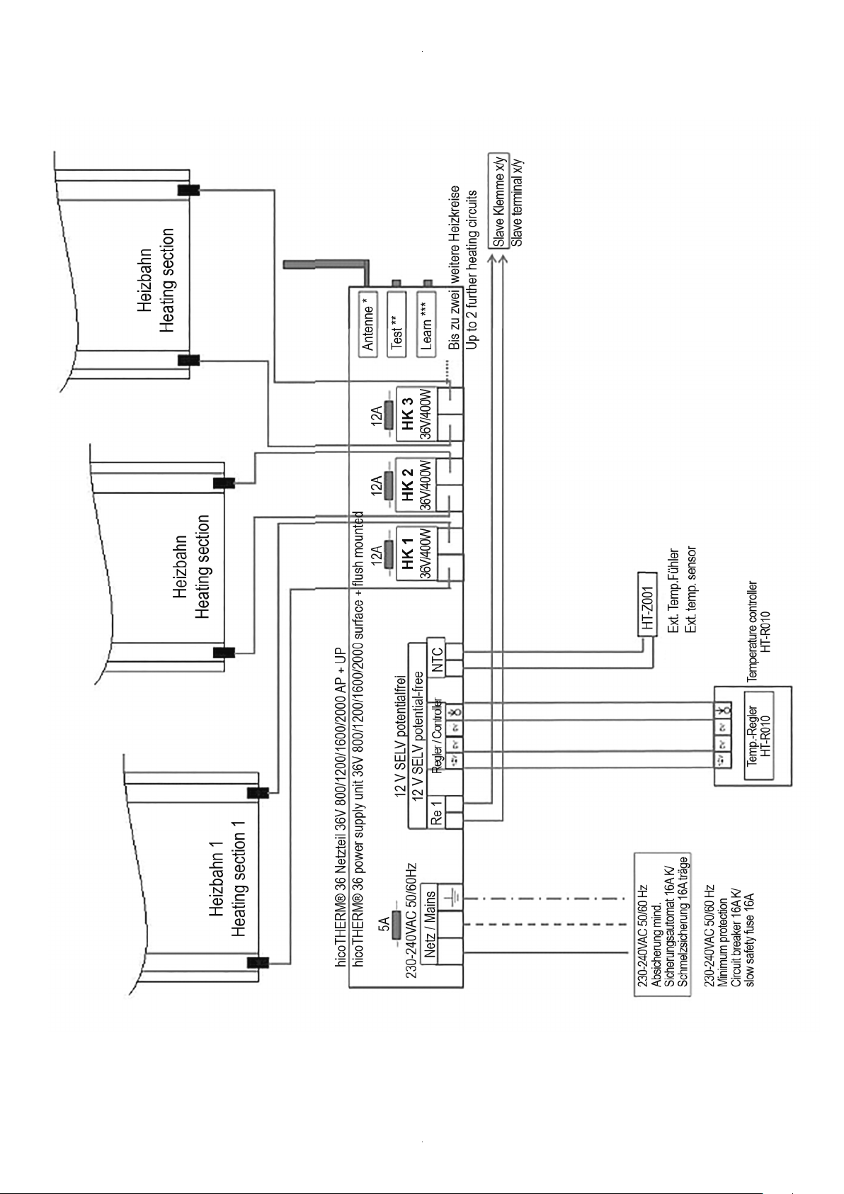
MONTAGE-SKIZZE:
INSTALLATION DRAWING:
Bitte unbedingt aufbewahren
Please make sure you keep this
Heizfolie
Heating film TransformerControl unit
2
Regelgerät Trafo
Thermofühler
Temperature sensor
Page 3

Bedienungsanleitung und
Installation and operating
Montageanweisung
hicoTHERM® 36-60
Temperierungs- und Sanierungssystem
hicoTHERM® 36-110
Heizungssystem
hicoTHERM® 36-220
Heizungssystem
instructions
hicoTHERM® 36-60
Temperature regulation and renovation system
hicoTHERM® 36-110
Heating system
hicoTHERM® 36-220
Heating system
Inhaltsverzeichnis
0 MONTAGE-SKIZZE
1 AUSLIEFERZUSTAND
1.1 Lieferumfang
2 INFORMATIONEN FÜR BENUTZER
2.1 Allgemeines
2.2 Funktion und Anwendung
2.3 Bedienung
2.4 Wartung
3 MONTAGE
3.1 Vorbereitung
3.2 Verlegung
3.2.1 Vorbehandlung des Untergrunds
3.2.2 Wärmedämmung
3.2.3 Verlegearten
3.2.4 Einbau unter Fliesen
3.2.5 Deckeneinbau
3.2.6 Einsatz in Feucht-/Nassräumen
3.3 Elektrischer Anschluss
3.4 Inbetriebnahme
Contents
0 INSTALLATION DRAWING
1 CONFIGURATIONS AVAILABLE
1.1 System contents
2 INFORMATION FOR USERS
2.1 General
2.2 Function and use
2.3 Operation
2.4 Maintenance
3 INSTALLATION
3.1 General preparation
3.2 Installation
3.2.1 Preparation of the substructure
3.2.2 Heat insulation
3.2.3 Installation options
3.2.4 Installation underneath tiles
3.2.5 Installation in ceilings
3.2.6 Installation in wet conditions
3.3 Electrical connection
3.4 Start-up
4 TECHNISCHE DATEN
5 GEWÄHRLEISTUNG UND GARANTIE
6 GARANTIE-KARTE
..................................................................................................................
4 TECHNICAL DATA
5 WARRANTY AND GUARANTEE
6 WARRANTY CARD
.....................................................................................................................
3
Page 4

1 AUSLIEFERZUSTAND
1 CONFIGURATIONS AVAILABLE
Das Flächenheizungssystem hicoTHERM® 36 kann als Vollheizung, Zusatzheizung oder zur Oberflächentemperierung in der Sanierung (z.B.
Schimmelprävention) eingesetzt werden.
1.1 Lieferumfang
Das hicoTHERM® 36-System besteht aus folgendem Lieferumfang:
• Konfektionierte hicoTHERM® 36 Heizfolie in 60/110/220 W/m
2
• Netzteil
• Unterputz bis 1600 W
• Aufputz bis 2000 W
• Montageanleitung
• Regler
Lieferbar sind verschiedene Temperaturregler in der Ausführung drahtgebunden oder Funk.
2 INFORMATIONEN FÜR BENUTZER
Bitte vor Installation diese Bedienungsanleitung sorgfältig lesen und die
Hinweise befolgen. Das hicoTHERM® 36-System kann von Kindern ab 8
Jahren und darüber sowie von Personen mit verringerten physischen,
sensorischen oder mentalen Fähigkeiten oder Mangel an Erfahrung
und Wissen benutzt werden, wenn sie beaufsichtigt oder bezüglich des
sicheren Gebrauchs des Gerätes unterwiesen wurden und die daraus
resultierenden Gefahren verstehen. Kinder dürfen nicht mit dem Gerät
spielen. Reinigung und Benutzer-Wartung dürfen nicht von Kindern
ohne Beaufsichtigung durchgeführt werden.
Eine Kopie der Bedienungsanleitung ist im Stromkreisverteiler aufzubewahren. Bei Besitzerwechsel den Nachbesitzer bitte über die Installation informieren. Im Feucht/Nassräumen muss die DIN VDE 0100 Teil
701 berücksichtigt werden. Wenn die hicoTHERM® Heizfolie unter einem
z.B. Fliesenbelag (vorzugsweise unterhalb der Abdichtung) im Feucht-/
Nassbereich (z.B. Dusche) eingebaut wird, zählt dieser Bereich nicht zu
den Schutzbereichen 0, 1 oder 2 nach DIN VDE 0100 Teil 701. Der Einbau
ist unter diesen Voraussetzungen zugelassen.
The hicoTHERM® 36 radiant heating system can be used as a comprehensive or supplementary heating source or for temperature regulation
in renovation projects (e.g. prevention of mould).
1.1 System contents
The hicoTHERM® 36 system consists of the following:
• Ready-to-use hicoTHERM® 36 heating film (60/110/220 W/m2):
• Power supply unit
• Flush-mounted up to 1,600 W
• Surface-mounted up to 2,000 W
• Installation instructions
• Controller
Various temperature controllers are available in wired or wireless configurations.
2 INFORMATION FOR USERS
Please read these instructions through carefully before starting installation and follow the instructions. The hicoTHERM® 36 system can be
used by children who are 8 years old or older as well as by people who
are physically, sensorily or mentally challenged or lack experience and
know-how, provided that they are supervised or have been instructed
about how to use the equipment safely and understand the dangers involved. Children must not be allowed to play with the equipment. Cleaning and user maintenance must not be carried out by children without
supervision.
A copy of the instruction manual must be kept in the distribution box.
If there is a change in ownership, please provide the new owner with
the installation information. Section 701 of DIN VDE 0100 must be taken
into account in wet conditions. When the hicoTHERM® heating film is
installed in wet conditions (e.g. shower), for example underneath tiles
(preferably underneath the sealing), this area is not included in protection areas 0, 1 or 2 as specified in DIN VDE 0100 Section 701. Installation is
permitted under these conditions.
2.1 Allgemeines
Das hicoTHERM® 36 System ist auf Sicherheit geprüft. Bei Arbeiten am
Heizsystem ist die Bedienungsanleitung dem Monteur zur Kenntnisnahme zu übergeben.
Das hicoTHERM® 36 lässt sich unauffällig in Decke, Wand oder Boden
verbauen. Zur Montage ist ein Verlegeplan zum Auffinden und Positionsbestimmung der Heizfolien, Netzteile, elektrischen Zuleitungen und
ggf. des Temperaturfühlers zu erstellen (siehe Skizze 3.1).
Um die optimale Funktionsfähigkeit des Systems zu gewährleisten ist
eine qualifizierte Dimensionierung und Planung (z.B. Heizlastberechnung DIN EN 12831) empfehlenswert.
Bei Wand- oder Bodenflächen ist darauf zu achten, dass die Heizflächen
nicht verstellt werden. Hier ist eine entsprechende Kennzeichnung der
Produkte (Herstellerfreigabe für elektrische Flächenheizung) zu prüfen
und die Dicke und Wärmeleitfähigkeit λ [W/(mK)] bzw. der sich daraus ergebende Wärmedurchlasswiderstand Rλ [m2K/W] zu beachten.
Der maximale Wärmedurchlasswiderstand des Bodenbelags, inklusive der zum Bodenbelag gehörenden Unterlage, darf den Wert von
Rλ = 0,15 m2K/W nicht überschreiten.
4
2.1 General
The hicoTHERM® 36 system has been tested to make sure it is safe.
When work is being done on the heating system, these instructions
must be given to the fitter for his information.
hicoTHERM® 36 can be installed inconspicuously in the ceiling, in the
wall or under the floor. Before installation begins, an installation plan
must be drawn to find and determine the position of the heating films,
the power supply units, the electrical supply lines and – if applicable –
the temperature sensor (see drawing 3.1). In order to guarantee optimum system viability, it is advisable to carry out accurate dimensioning
and planning (e.g. heating load calculation / DIN EN 12831). In the case
of wall or floor surfaces, care needs to be taken to make sure that the
heating areas are not covered.
The products need to be checked to make sure they are designed for
such systems (manufacturer’s approval for electrical radiant heating
applications), with particular attention being paid to the information
provided about thickness and heat conductivity λ [W/(mK)] and/or the
heat transfer resistance Rλ [m2K/W] resulting from this. The maximum
heat transfer resistance of the floor covering, including the underlay
that forms part of the floor covering, must not exceed Rλ = 0,15 m2K/W.
Page 5
Eine optimale und schnelle Wärmeverteilung erreicht man mit sehr
dünnen Belägen (Tapete, Putzsysteme, keramische Beläge).
Optimum, fast heat distribution is achieved with very thin coverings
(wallpaper, plaster systems, ceramic coverings).
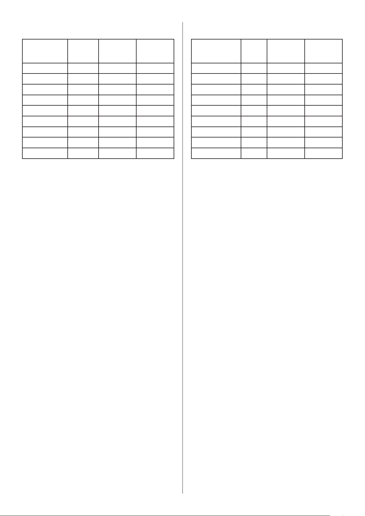
Material Dicke [mm] Wärmeleit-
fähigkeit
λ [W/(mk)]
Keramische Fliesen 13 1,05 0,012
Natursteinplatten 12 1,2 0,010
Teppichboden – – 0,07 - 0,17
Nadelvlies 6,5 0,54 0,12
Linoleum 2,5 0,17 0,015
PVC-Belag 2,0 0,20 0,010
Echtholz-Parkett 11 - 14 0,09 - 0,12 0,055 - 0,076
Laminat 9 0,17 0,05
Kork - Korklaminat 3 - 10 0,12 - 0,10 0,027 - 0,102
Planungsrichtwerte für Bodenbeläge auf Fußbodenheizung.
Das System wird mit Schutzkleinspannung 36V betrieben und bietet somit ein Höchstmaß an elektrischer Sicherheit.
Der Anschluss des Netzteils an das Hausnetz, sowie die Installation des
Temperaturreglers und der Heizfolien darf nur durch eine Elektrofachkraft durchgeführt werden.
Wärmedurchlasswiderstand
R λ [m2K/W]
Material Thickness
[mm]
Ceramic tiles 13 1,05 0.012
Natural stone slabs 12 1.2 0.010
Carpeting – – 0,07 - 0,17
Needlemat 6.5 0.54 0.12
Linoleum 2.5 0.17 0.015
PVC 2.0 0.20 0.010
Parquet flooring 11 - 14 0.09 - 0.12 0.055 - 0.076
Laminate 9 0.17 0.05
Cork – cork laminate 3 - 10 0.12 - 0.10 0.027 - 0.102
Approximate planning figures for floor coverings with underfloor heating.
The system is operated at extra-low voltage (36V), so that it provides maximum electrical safety.
Trained electricians must be deployed to connect the power supply unit
to the mains system in the building as well as to install the temperature
controller and the heating films.
Heat
conductivity
λ [W/(mk)]
Heat transfer
resistance
R λ [m2K/W]
2.2 Funktion und Anwendung
Das hicoTHERM® 36-System ist eine auf Strahlungswärme optimierte
Folienheizung für Wand, Decke und Fussboden, die sich durch eine sehr
geringe Aufbauhöhe auszeichnet und unmittelbar an der Oberfläche
eine äußerst schnelle Erwärmung einzelner Flächenbereiche gewährleistet. Es findet in den vielfältigsten Bereichen z.B. in Wohnräumen,
Dachausbauten, Fitness- und Saunabereichen, Wintergärten, Sitzbereichen, Schimmelprävention usw. Anwendung. Das hicoTHERM® 36-Heizungssystem ist entsprechend der gültigen EN 60335-1 und EN 603352-96 zugelassen.
Generell bei Strahlungsheizungen ist es sinnvoll, die tatsächliche Oberflächentemperatur des Heizelementes durch einen Temperaturregler
mit Thermofühler zu regeln.
Verwenden Sie pro Raum einen Regler und für den Bodeneinbau zusätzlich einen Temperaturfühler zur Erfassung und Begrenzung der Oberflächentemperatur an der Heizfläche.
Die Heizungsfolie ist generell geeignet für das nachträgliche Einbringen
von Löchern mit maximaler Größe von 70 mm (siehe Skizze unter 3.1).
Beachten Sie auch den Mindestabstand von 20 mm zwischen den Bohrungen und zu den Kupferleitern (siehe 3.1).
Der Kupferstreifen auf der Heizbahn darf nicht beschädigt oder eingeschnitten werden.
2.2 Function and use
The hicoTHERM® 36 system is a film heating system with optimised
radiant heating that is designed for walls, ceilings and floors, is very
thin and guarantees extremely fast direct surface heating of individual
areas. It can be used in many different contexts, e.g. in living areas,
attic conversions, fitness and sauna facilities, conservatories, seating
areas, mould prevention etc. The hicoTHERM® 36 heating system is
approved for use in accordance with the latest version of EN 60335-1 and
EN 60335-2-96.
With radiant heaters in general, it is advisable to use a temperature controller with a temperature sensor to regulate the actual surface temperature of the heating area.
Use one controller per room in addition to a temperature sensor for floor
installation to determine and limit the surface temperature of the heating area.
It is generally possible for holes with a maximum size of 70 mm to be
made in the heating film subsequently (see the drawing in 3.1). Care
needs to be taken in addition that the holes are at least 20 mm away
from each other and from the copper conductors (see 3.1).
The copper strip on the heating section must not be damaged or cut
into.
2.3 Bedienung
Das hicoTHERM® 36 System besticht durch die einfache Handhabung
der Installation und Bedienung.
Zum Erreichen der Wohlfühltemperatur wird der Regler auf den gewünschten Wert eingestellt. Die Raumtemperaturregelung erfolgt
dann automatisch.
Die tatsächliche Oberflächentemperatur, bzw. Aufheizgeschwindigkeit der Heizflächen sind abhängig vom jeweiligen Deckbelag und der
Wärmedämmung des Untergrunds und können von der eingestellten
Raumtemperatur abweichen.
2.3 Operation
Simple installation and operation are the outstanding features of the
hicoTHERM® 36 system.
The controller is set to the required level to adjust the room temperature
to the level you feel happy with. After this, room temperature regulation
is carried out automatically.
The actual surface temperature and heating-up speed of the heating
areas depend on the covering and the heat insulation of the substructure and may differ from the room temperature setting.
5
Page 6
Bei der Auswahl der Raumtemperaturregler sind die Vorgaben der
Ökodesign Richtlinie 2009/125/EG zu beachten. Demzufolge müssen
Raumtemperaturregler die folgenden Mindestanforderungen erfüllen:
• Elektronische Einzeltraumtemperaturregelung mit Wochentags regelung
The specifications included in the ecodesign directive 2009/125/EC must
be observed when choosing the room temperature controllers. Room
temperature controllers are required to satisfy the following minimum
requirements:
• Electronic individual room temperature control with week timer
Zusätzlich müssen mindestens 2 der folgenden 3 Regelungsfunktionen
erfüllt werden:
• Raumtemperaturkontrolle mit Erkennung offener Fenster
• Fernbedienungsoption
• Adaptive Regelung des Heizbeginns
2.4 Wartung
Das hicoTHERM® 36 Heizungssystem ist wartungsfrei.
Bei einem Störfall können folgende Schritte Abhilfe schaffen:
• Überprüfen Sie bitte den Temperaturregler, z.B. die Störanzeige am
Display.
• Überprüfen Sie die Fehleranzeige am Netzteil.
• Überprüfen Sie die Sicherung der Spannungsversorgungen und die
hausinternen Sicherungen oder den FI-Schutzschalter.
Bei unveränderter Störung benachrichtigen Sie einen zugelassenen
Elektrofachmann oder Ihren hicoTHERM®-Fachhändler.
Generell wird empfohlen, das System nach fünf Jahren von einem zugelassenen Elektrofachmann überprüfen zu lassen.
3 MONTAGE
In addition to this, at least 2 of the following 3 control functions must
be carried out:
• Room temperature control with open window detection
• Remote control option
• Adaptive start control
2.4 Maintenance
The hicoTHERM® 36 heating system requires no maintenance.
If problems occur, the following activities may be helpful:
• Please check the temperature controller, e.g. the fault display.
• Check the fault display on the power supply unit.
• Check the power supply and building fuses or circuit breakers.
If the fault is not eliminated, inform a licensed electrician or your
hicoTHERM® dealer.
It is in general recommended that the system is checked by a licensed
electrician every five years.
3 INSTALLATION
3.1 Vorbereitung
Die hicoTHERM® 36-Systeme sind für den Innenbereich an Boden, Wand
und Decke geeignet.
Die Auswahl der zu verwendeten Heizfläche richtet sich nach den später
beabsichtigten Stellflächen für Möbel und Beläge sowie einer optimalen
Wärmeeinbringung. Dazu sei noch einmal auf den Punkt 2.1 der Bedienungsanleitung verwiesen.
Die hicoTHERM® 36-Heizfolie ist nicht für den Verbau als Speicherheizung konzipiert und damit nicht für den Verbau innerhalb des Bodenestrichs zu verwenden. Je näher die Heizfolie zur Raumoberfläche
verbaut wird, desto schneller reagiert das Heizsystem und gibt die wohltuende Wärmestrahlung in den Raum ab.
Zur Erleichterung ihrer persönlichen Planung und Dokumentation der
Verlegearbeiten sollten Sie die Montage-Skizze (Seite 2) benutzen.
Die Heizfolien werden nach Kundenvorgabe konfektioniert und können
nachträglich gekürzt werden (siehe Skizze 3.1). Die Folie ist elektrisch
stets an den vormontierten Kontakten zu kontaktieren.
3.1 General preparation
hicoTHERM® 36 systems are suitable for inside floors, walls and ceilings.
The heating area chosen is determined on the basis, firstly, of where furniture and coverings are planned subsequently and, secondly, of optimum heat distribution. Attention is again drawn to point 2.1 of these
instructions in this context.
The hicoTHERM® 36 heating film is not designed for installation as a storage heating system and should not therefore be incorporated in floor
screed. The closer the heating film is to the room surface, the faster the
heating system responds and the faster the pleasant radiant heat reaches the room.
You should use the installation drawing (page 2) to facilitate your personal planning and to document the installation work.
The heating films are supplied in accordance with the customer’s specifications and can be shortened subsequently (see drawing 3.1).
The pre-assembled contacts must always be used to establish the necessary electrical contacts.
6
Page 7

3.2 Verlegung
Dieser Abschnitt bezieht sich auf die Verlegung der Folie und des Trafos.
Die Verlegung der Leitungen und der elektrischen Anschlüsse ist im Abschnitt 3.3 Elektrischer Anschluss erklärt. Berücksichtigen Sie die Mindestverarbeitungstemperatur von +5°C.
Bei Wänden unterhalb von 2,3 m Höhe und in Decken, die weniger als
45° zur Senkrechten geneigt sind, sollte die Heizfolie ca. 15 cm kürzer als
die Länge der Montagefläche sein. Die Heizfolie kann bei Bedarf senkrecht zu den Kupferbahnen einmalig geteilt werden. Beschnitte immer
nur von der unkontaktierten Seite der Heizfolie vornehmen.
Jede andere unsachgemäße Beschädigung der Folie wie z. B. Einrisse
durch scharfe Gegenstände oder Knicke sind zu vermeiden. Bewahren Sie
die Heizfolie deshalb bis zum Einbau im gerollten Zustand in der Verpackung auf (Mindestbiegeradius beachten, siehe 4. TECHNISCHE DATEN).
Nach erfolgter Verlegung können jedoch Löcher, wie in Abschnitt 2.2
Funktion und Anwendung beschrieben, eingebracht werden.
Warnhinweis:
Beachten Sie, dass Schrauben nur dann in die Heizfläche eingebracht
werden dürfen, wenn diese mit Kunststoffdübeln zur elektrischen Isolation installiert werden. Zusätzlich dürfen zwei Schrauben nicht mit einem
elektrisch leitfähigen Material (z.B. Metallbilderrahmen, Metallzierleiste,
Regalsystem aus Metall) verbunden werden. Verwenden Sie keine Nägel.
3.2 Installation
This section relates to installation of the film and the transformer. Installation of the supply lines and the electrical connections is explained
in Section 3.3 Electrical connection. Note that the minimum processing
temperature is +5 °C.
When walls are less than 2.3 m high and ceilings slope less than 45°, the
heating film should be about 15 cm shorter than the length of the installation area. If necessary, the heating film can be divided once at right
angles to the copper conductors. Make sure that cutting is always from
the uncontacted side of the heating film.
All other inappropriate damage to the film, such as tears caused by
sharp objects or kinks, must be avoided. It is therefore important to keep
the heating film rolled up in its packaging until it is required for installation (note the minimum bending radius, see 4. TECHNICAL DATA).
After installation has been completed, holes may, however, be made in
the film, as outlined in Section 2.2 Function and use.
Warning:
Note that screws may only be fitted in the heating surface if they are installed with plastic plugs for electrical insulation purposes. In addition
to this, two screws may not be connected by a material that conducts
electricity (e.g. metal picture frames, decorative metal trim, metal shelving system). Do not use any nails.
3.2.1 Vorbehandlung des Untergrunds
Die Heizfolie kann auf jedem tragfähigen, sauberen und ebenen Untergrund aus anorganischen Materialien wie Stein, Estrich, Putz, etc. oder
organischen Materialien wie Holz, Kork, Kunststoff (evtl. mit Oberflächengrundierung / Haftvermittler), etc. angebracht werden. Die Unter- und Deckschichtmaterialien müssen bis 70 °C temperaturbeständig
sein. Im Zweifel kontaktieren Sie den Hersteller dieser Materialien.
Unregelmäßige Oberflächen sind zu vermeiden (z.B. sichtbare Holz/
Stein - Ausmauerungen). Unter Umständen ist die Fläche vorab mit Ausgleichsputz oder Nivelliermasse auszugleichen.
Es ist besonders darauf zu achten, dass keine spitzen Erhebungen wie
Steine, Schraubenköpfe, Nägel oder ähnliches aus dem Untergrund hervorstehen.
3.2.1 Preparation of the substructure
The heating film can be applied to any viable, clean and flat substructure
made from inorganic materials like stone, screed, plaster etc. or organic
materials like wood, cork, plastic (possibly with surface finishing / a tie la
yer) etc. The substrate and top layer materials must resist temperatures
of up to 70°C. Contact the manufacturer of these materials if you are in
any doubt.
Irregular surfaces must be avoided (e.g. visible wood/stone – brickwork).
Under certain circumstances, the surface may need to be evened out beforehand with plaster or a levelling compound.
Particular care must be taken to make sure that no pointed objects like
stones, screw heads, nails etc. are projecting out of the substructure.
7
Page 8
Für eine schwimmende Verlegung ohne Verklebung, z.B. zwischen
Estrich und Laminat, empfehlen wir, eine ca. 2 mm ausgleichende Korkschicht oder Glasfaservlies unter der Heizfolie zu verlegen.
If the heating film is being installed without adhesive, e.g. between screed
and laminate, we recommend the inclusion of roughly 2 mm of a cork layer
or fibreglass matting underneath the heating film to compensate for this.
3.2.2 Wärmedämmung
Eine Wärmedämmung im Boden und Wandbereich ist zu empfehlen,
um die Wärmeabgabe ins Mauerwerk und den Boden zu reduzieren.
Um den Wärmefluss nach unten zu begrenzen, ist folgendes Mindestverhältnis der Wärmedurchgangskoeffizienten des Fußbodenaufbaues
oberhalb der Dämmschicht und des Wärmedurchgangskoeffizienten
für alle Schichten unterhalb der Lastverteilschicht einzuhalten (nach EN
50559:2013-12):
• Zwischengeschossdecke, über beheizten Räumen:
U max: 1,25 W/(m2*K)
• Zwischengeschossdecken über teilweise beheizten Räumen:
U max: 0,75 W/(m2*K)
• Kellerdecken, Wände und Decken gegen unbeheizte Räume sowie
Decken und Wände, die an das Erdreich grenzen:
U max: 0,35 W/(m2*K)
Die Dämmschichten unter der Fußbodenkonstruktion sind nach folgender Tabelle zu wählen. Mindest-Wärmedurchgangskoeffizienten
sind einzuhalten. Es dürfen nur genormte, für Fußbodenheizung geeignete Dämmstoffe verwendet werden. Die Zusammendrückbarkeit der
Dämmschicht darf nicht mehr als 5 mm betragen. Bei mehreren Lagen
ist die Zusammendrückbarkeit der einzelnen Lagen zu addieren.
3.2.2 Heat insulation
Heat insulation in the floor and walls is recommended, in order to reduce the loss of heat to the walls and floor. To limit heat radiation downwards, the following minimum ratio of the heat transfer coefficient of
the floor structure above the insulation layer and the heat transfer coefficient of all layers underneath the load distribution layer must be observed (according to EN 50559:2013-12):
• Intermediate ceilings, above heated rooms:
U max: 1.25 W/(m2*K)
• Intermediate ceilings, above rooms that are heated to some extent:
U max: 0.75 W/(m2*K)
• Cellar ceilings, walls and ceilings next to unheated rooms as well as
ceilings and walls adjacent to earth:
U max: 0.35 W/(m2*K)
The insulation layers below the floor structure must be chosen in accordance with the following table. Minimum heat transfer coefficients
must be observed. Standardised insulation materials that are suitable
for underfloor heating must be used. The insulation layer must not be
compressible by more than 5 mm. If there are several layers, the compressibility of the individual layers is added together.
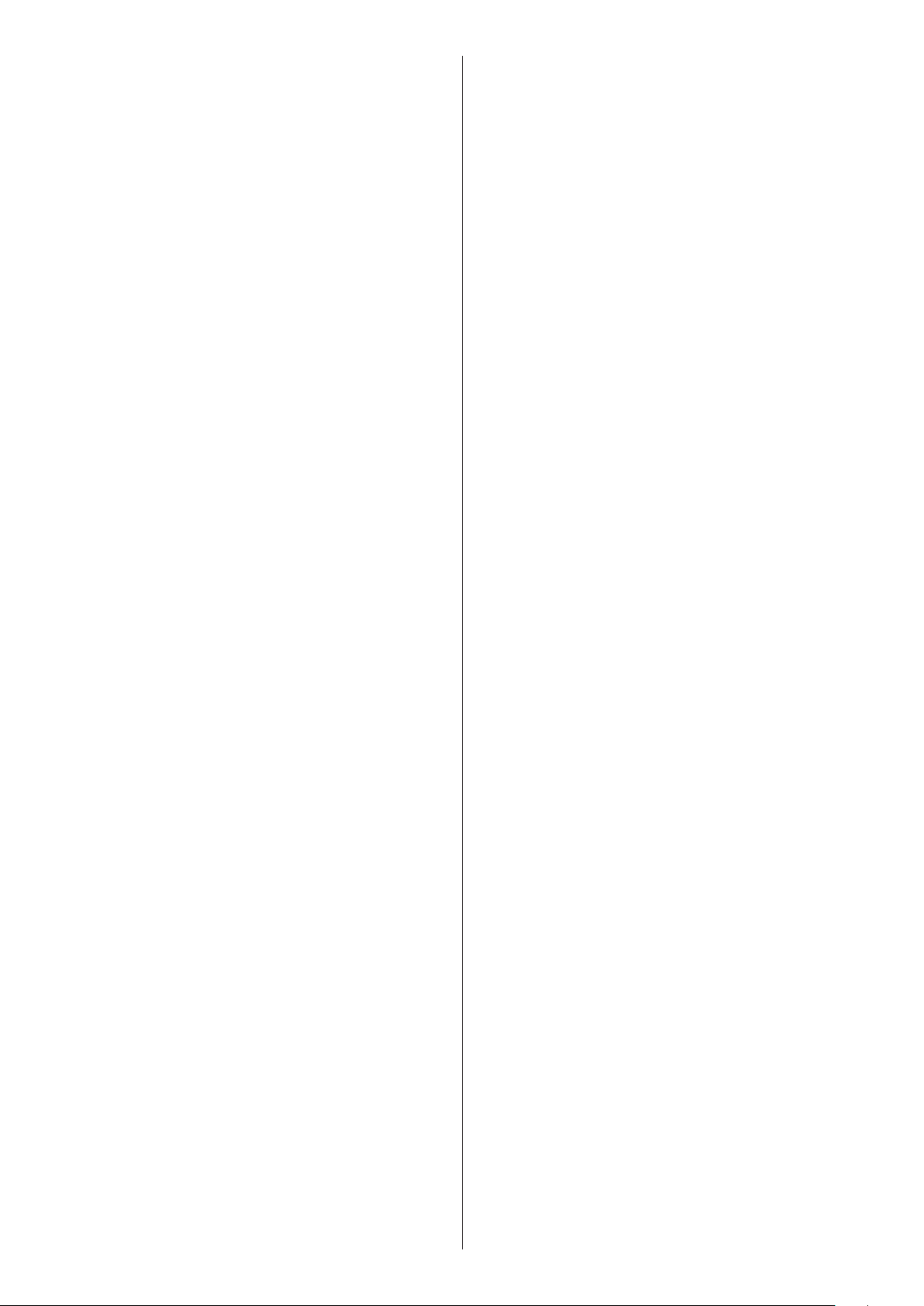
U
R
min
m2*K/W
Zwischengeschossdecken über beheizten
Räumen
Zwischengeschossdecken über teilweise
beheizten Räumen
max
W/(m2*L)
1,25 0,75
0,75 1,25
Heizflächen zwischen Außenluft oder Erdreich 0,35 2,86
Kellerdecken, Wände oder Decken gegen
unbeheizte Räume
0,35 2,86
Mindest-Wärmedurchgangskoeffizient und Mindest-Wärmeleitwiderstand der Bauteile.
U
max
W/(m2*L)
R
min
m2*K/W
Intermediate ceilings above heated rooms 1.25 0.75
Intermediate ceilings above rooms that are
heated to some extent
0.75 1.25
Heating areas between outside air or earth 0.35 2.86
Cellar ceilings, walls or ceilings next to unheated rooms
0.35 2.86
Minimum heat transfer coefficient and minimum heat conductivity of
the components.
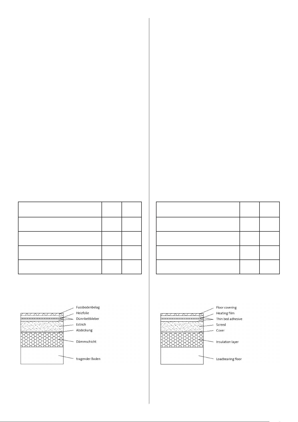
Wärmedämmung und Verlegung als Direktheizung im Dünnbettkleber Heat insulation and installation as direct heating in thin bed adhesive
8
Page 9

3.2.3 Verlegearten
3.2.3 Installation options
Es gibt drei verschiedene Verlegearten:
(A) Einbetten der Folie zwischen anorganischen Schichten mit Disper
sions-Spachtelmassen oder Dispersions Putzsysteme wie z.B.
Schönox FS, Brillux PM1881 oder Maxit K+B.
(B) Verkleben der Folie zwischen anorganischen und organischen
Schichten mit allen Arten von flexiblen Klebern wie unter (A)
beschrieben.
(C) Schwimmende Verlegung an Boden und Decke als oberste Schicht
unter der Deckschicht.
In den Fällen (A) - (B) ist die Folie im Dünnbettverfahren im feuchten
Kleberbett ohne Luftblasen einzuarbeiten. Dazu das Kleberbett 1-2 mm
stark auf den Untergrund auftragen, anschließend die Folie in das noch
feuchte Bett vorsichtig mit einer Kunststoffkelle eindrücken. Danach
mit dem gleichen Klebesystem eine dünne Deckschicht (1-2 mm) auf die
Heizfolie aufziehen und abschließend die Deckschicht möglichst eben
abziehen und für den weiteren Belag vorbereiten.
Es ist darauf zu achten, dass die Folie nicht über Soll-Dehnfugen verlegt
wird. Bei kleineren Dehnungsrissen, z.B. bei Fliesenfugen im Bereich 1-2
mm, sind flexible Klebersysteme zu empfehlen.
There are three different installation options:
(A) Incorporation of the film between inorganic layers with dispersion
spackling pastes or dispersion plaster systems, such as Schönox FS,
Brillux PM1881 or Maxit K+B.
(B) Gluing of the film between inorganic and organic layers with all
kinds of flexible adhesives, as outlined in (A).
(C) Floating installation on floors and ceilings as the uppermost layer
underneath the top layer.
The film must be incorporated in the moist adhesive bed by the thin bed
process without any air bubbles in the cases (A) – (B). To do this, apply
the adhesive bed 1 – 2 mm thick to the substructure and then carefully
press the film into the bed while it is still moist using a plastic trowel.
Put a thin covering layer (1 – 2 mm) on top of the heating film afterwards
using the same adhesive system and finally make the top layer as smooth as possible in preparation for the final covering.
Care must be taken to make sure that the film is not installed above joints
that are meant to expand. Flexible adhesive systems are recommended
in the case of minor expansion cracks, e.g. tile joints in the 1 – 2 mm range.
Sollen mehrere Heizungsbahnen nach Verlegeart (C) schwimmend
nebeneinander verlegt werden, so ist darauf zu achten, dass die Heizbahnen mit einem Klebeband gegen Verrutschen gesichert werden
und zwischen den einzelnen Folien ein Mindestabstand von 20 mm
eingehalten wird. Die Heizbahnen und Kupferkontaktstreifen dürfen
sich bei mehrbahniger Verlegung nicht berühren oder kreuzen.
Zur Installation des Reglers und Fühlers siehe Abschnitt 3.3 Elektrischer
Anschluss.
3.2.4 Einbau unter Fliesen
Vor der Verklebung der Fliesen muss die Heizfolie mit flexiblem Fliesenkleber vollständig in einem Dünnbettverfahren und einer 1-2 mm starken Deckschicht verlegt werden. Die Oberfläche muss nach Vorschrift
des Kleberherstellers getrocknet sein. Bei der Verlegung von mehreren
Bahnen ist auf einen ebenen Ausgleich zu achten.
3.2.5 Deckeneinbau
Bei der Installation der hicoTHERM® 36-Heizfolie in einer abgehängten
Decke oder wenn diese von einem Dachraum zugänglich ist, muss ein
Warnschild „Deckenheizung direkt wirkend“ an der Zugangsöffnung der
Decke angebracht werden.
If several heating sections are to be installed without bonding next to
each other (installation option “C”), care must be taken to make sure
that the heating sections are protected against slippage by applying adhesive tape and that there is a minimum distance of 20 mm between
the individual sections of film. If several different heating sections are
installed next to each other, the individual sections and the copper contact strips must not touch or cross each other.
See Section 3.3 Electrical connection for information about installation
of the controller and sensor.
3.2.4 Installation underneath tiles
Before the tiles are glued, the heating film must be installed completely
by a thin bed process with flexible tile adhesive and a top layer 1 – 2 mm
thick. The surface must be dried in accordance with the instructions issued by the adhesive manufacturer. When several different sections are
being installed, care must
3.2.5 Installation in ceilings
When hicoTHERM® 36 heating film is being installed in a suspended ceiling or when the film is accessible from an attic, a warning sign “Ceiling
heating – direct impact” must be attached to the access opening to the
ceiling.
3.2.6 Einsatz in Feucht-/Nassräumen
Beim Einsatz in Feucht-/Nassräumen sind die Vorgaben aus der DIN VDE
0100 Teil 701 zu berücksichtigen. Der Trafo und die sonstigen Komponenten sind grundsätzlich für den Einsatz in Feucht- und Nassräumen
geeignet, dürfen jedoch nur außerhalb des Schutzbereich 2 installiert
werden.
3.2.6 Installation in wet conditions
When installation is being carried out in wet conditions, the specifications made in section 701 of DIN VDE 0100 must be observed. The
transformer and the other components are basically suitable for use in
wet conditions, but may only be installed outside protection area 2.
9
Page 10

3.3 Elektrischer Anschluss
3.3 Electrical connection
Die Installation der elektrischen Komponenten darf nur durch einen zugelassenen Elektrofachmann erfolgen. Für das Heizungssystem ist eine allpolige Trennvorrichtung vom Netz mit mindestens 3 mm Kontaktöffnungsweite je Pol in die feste Installation vorzusehen. Vor der Inbetriebnahme
der Anwendung sind alle Verbindungen und Schrauben zu überprüfen.
Als indirekten Berührungsschutz ist ein Fehlerstromschalter (FI mit 30
mA) notwendig.
An den einzelnen Lastausgängen der Netzteile dürfen jeweils nur maximal 400 W angeschlossen werden. Die Maximallängen der einzelnen
Heizbahnen sind:
hicoTHERM® 36-60 max. 11 m
hicoTHERM® 36-110 max. 6 m
hicoTHERM® 36-220 max. 3 m
Werden mehrere kurze Bahnen an einem Ausgang angeschlossen muss
explizit darauf geachtet werden den Höchstwert von 400 W pro Heizkreis nicht zu überschreiten.
Der optional erhältliche Temperaturfühler ist direkt, oder mittels einem
Leerrohr unter und möglichst nahe an die Heizfolienoberfläche zu installieren und an das Netzteil, bzw. Temperaturregler HT-R010 anzuschließen (siehe Bedienungsanleitung).
Der Anschluss und Inbetriebnahme muss von einer Elektrofachkraft
durchgeführt werden.
A licensed electrician must be deployed to install the electrical components. An all-pole mains disconnection facility with a contact opening
width per pole of at least 3 mm must be provided for the heating system
during installation. All the connections and screws must be checked before the system is started up.
A circuit breaker (FI with 30 mA) is necessary as indirect contact protection.
A maximum of only 400 W in each case may be connected to the individual load outputs of the power supply units. The maximum lengths of
the individual heating sections are:
hicoTHERM® 36-60 max. 11 m
hicoTHERM® 36-110 max. 6 m
hicoTHERM® 36-220 max. 3 m
If several short sections are connected to one output, special care must
be taken to make sure that the maximum of 400 W per heating circuit
is not exceeded.
The temperature sensor available as an optional extra must be installed
via an empty conduit underneath and as close as possible to the heating
film surface and must be connected to the power supply unit and/or
temperature control unit HT-R010 (see the installation instructions).
Connection and start-up must be carried out by a trained electrician.
Achtung:
Weichen die Widerstandsmesswerte mehr als 15 % vom Ausgangswert
ab, so ist mit einer Beschädigung der Kontakte oder der Heizfolie zu rechnen. In diesem Fall dürfen Sie das Heizsystem nicht in Betrieb nehmen.
Die Netzteile können je nach Ausführung Auf- oder Unterputz verbaut
werden. Dazu ist ein Mindestabstand von 50 mm zur Folie einzuhalten.
Die maximale Leitungslänge auf der Sekundärseite des Netzteils darf
maximal betragen:
10 m bei 2,5 mm2 Kabel
25 m bei 6 mm2 Kabel
Wir empfehlen die Verwendung unser PUR-Kabellitze (Li11Yv) für die
Auf- und Unterputzinstallation.
Die Verlegung der elektrischen Leitungen hat nach der aktuell gültigen DIN VDE 0100 zu erfolgen. Die Temperaturregler werden je nach
Ausführung mittels Kabel-, oder Funkverbindung mit dem Netzteil verbunden.
3.4 Inbetriebnahme
Nach einer Mindesttrocknungszeit des Klebers (siehe Empfehlung des
Herstellers) und nach erfolgter elektrischer Inbetriebnahme kann das
hicoTHERM36-Heizsystem erstmalig aufgeheizt werden. Bringen Sie
nun das mitgelieferte Warnschild in unmittelbarer Nähe der Heizfolie
gut sichtbar an und hinterlegen Sie die Bedienungsanleitung im Verteilerkasten.
Important to remember:
If the resistance readings differ more than 15% from the original level,
damage to the contacts or the heating film must be expected. You must
not put the heating system into operation in this case.
The power supply units can be surface-mounted or flush-mounted, depending on the configuration. They must be at least 50 mm away from
the film. The maximum conductor length on the secondary side of the
power supply unit is:
10 m in the case of a 2.5 mm2 cable
25 m in the case of a 6 mm2 cable.
We recommend the use of our PUR cable conductors (Li11Yv) for surfacemounted or flush-mounted installation.
The electrical conductors must be installed in accordance with the
latest version of DIN VDE 0100. The temperature controllers are connected to the power supply unit either by wire or wirelessly, depending on
the configuration.
3.4 Start-up
The hicoTHERM® 36 heating system can be heated up for the first time
after a minimum adhesive drying period (see the manufacturer’s recommendation) and following electrical start-up. Attach the warning sign
supplied with the system now in a highly visible place in the immediate
vicinity of the heating film and put the instructions in the circuit breaker
panel box.
10
Page 11
Beispiel einer Einbausituation Example of an installation configuration
11
Page 12

4 TECHNISCHE DATEN
4 TECHNICAL DATA
Netzspannung: 230 V AC
Stromeinspeisung: 1,74 A je 400 W Belastung
Leistung
(hicoTHERM®36-Heizfolie): 60 W/m2 (hicoTHERM® 36-60)
110 W/m2 (hicoTHERM® 36-110)
220 W/m2 (hicoTHERM® 36-220)
Leistung pro Laufmeter: 35 W / lfm (hicoTHERM® 36-60)
65 W / lfm (hicoTHERM® 36-110)
130 W / lfm (hicoTHERM® 36-220)
Sekundärspannung: 36 V
Absicherung: 12 A AP
15 A UP
Schutzmaßnahme: FI-Schutzschaltung 30 mA
Nenngrenztemperatur: + 70 °C
Mindestverarbeitungstemperatur: + 5 °C
Minimaler Biegeradius: R10 mm
Material: PET-Folie mit Carbonfasern
und Füllstoffen
Primärleitung Netzteil: 1,5 mm2
Sekundärleitung Netzteil: 2,5 mm2, max. 10 m Länge
6,0 mm2, max. 25 m Länge
Heizfolienabmessung, Breite: 59 cm
54 cm (netto Heizbreite)
Maximallänge: hicoTHERM® 36-60 max. 11 m
hicoTHERM® 36-110 max. 6 m
hicoTHERM® 36-220 max. 3 m
Max. Wärmedurchlasswiderstand: Rλ für Bodenbelag: 0,15 m2 K/W
Mains voltage: 230 V AC
Power input: 1.74 A per 400 W load
Output
(hicoTHERM®36 heating film): 60 W/m2 (hicoTHERM® 36-60)
110 W/m2 (hicoTHERM® 36-110)
220 W/m2 (hicoTHERM® 36-220)
Output per metre: 35 W / m (hicoTHERM® 36-60)
65 W / m (hicoTHERM® 36-110)
130 W / m (hicoTHERM® 36-220)
Secondary voltage: 36 V
Fuse protection: 12 A surface-mounted
15 A flush-mounted
Protection measure: FI circuit breaker 30 mA
Nominal temperature limit: + 70 °C
Minimum processing temperature: + 5 °C
Minimum bending radius: R10 mm
Material: PET film with carbon fibres
and fillers
Primary conductor/power supply unit: 1.5 mm2
Secondary conductor/power supply unit: 2.5 mm2, max. 10 m length
6.0 mm2, max. 25 m length
Heating film dimensions, width: 59 cm
54 cm (net heating width)
Minimum lengths: hicoTHERM® 36-60 max. 11 m
hicoTHERM® 36-110 max. 6 m
hicoTHERM® 36-220 max. 3 m
Max. heat transfer resistance: Rλ for floor covering: 0.15 m2 K/W
Symbolerklärung:
a) Entsorgungshinweis: Das Produkt darf nicht im allgemeinen
Hausmüll entsorgt werden! Recycling über Elektronikentsorgung
der kommunalen Sammelstellen.
b) Zulässiger Einbau als Deckenheizung (direkt wirkend)
c) Zulässiger Einbau als Fußbodenheizung (direkt wirkend)
d) Bedienungsanleitung lesen, Anleitungen befolgen
e) Schutzklasse II
Explanation of symbols:
a) Waste disposal instructions: the product may not be disposed of in
general household waste! It must be recycled via the electronics
waste disposal system organised by the local authorities.
b) Approved for installation as a ceiling heating system (direct impact)
c) Approved for installation as an underfloor heating system
(direct impact)
d) Read and follow the instructions
e) Protection class II
12
Page 13

5 GEWÄHRLEISTUNG UND GARANTIE
5 WARRANTY AND GARANTEE
1.) Für unser hicoTHERM® Flächenheizsystem leisten wir Gewähr entsprechend der Vorschrift des deutschen Bürgerlichen Gesetzbuches.
Gegenüber privaten Endkunden ist die gesetzlich vorgeschriebene
Gewährleistungsfrist 2 Jahre. Auf fest mit dem Gebäude verbundene
Systemkomponenten, wie z.B. die hicoTHERM®-Heizfolien, räumen wir
eine Gewährleistungsfrist von 5 Jahren ein. Gegenüber Unternehmern
beträgt hiervon abweichend die Gewährleistungsfrist ein Jahr.
2.) Darüber hinaus geben wir auf unsere hicoTHERM® Flächenheizungsfolien eine Garantie von 5 Jahren, die sich an die gesetzliche Gewährleistungsfrist anschließt. Diese Garantie gilt für Endkunden, die unser
hicoTHERM® System als Neuprodukt erworben haben und bezieht sich
auf die Flächenheizungsfolien. Darüber hinaus ist Voraussetzung für
die Inanspruchnahme der Garantie, dass die Systeminstallation sowie
der elektrische Anschluss von einem Fachhandwerker durchgeführt
worden ist. Zur Inanspruchnahme der Garantie ist es erforderlich, dass
der Kunde die von dem Fachhandwerker ausgefüllte und von diesem
unterzeichnete Garantiekarte, die bei der Installation erstellt wird sowie
den Verlegeplan mit einer Kopie der Rechnung vorlegt. Bei Nichtvorlage
dieser Unterlagen ist eine Inanspruchnahme der Garantie nicht möglich.
Die Gewährleistungsfrist beginnt ab Endkunden-Rechnungsdatum.
Die Garantieleistung von Frenzelit umfasst zunächst die Prüfung, ob
ein Garantieanspruch besteht. Sollte ein Garantiefall vorliegen, so kann
Frenzelit die Art und Weise der Störungsbehebung selbst bestimmen. Es
steht Frenzelit frei, den nachgewiesenen Rechnungsbetrag der Heizfolie zu erstatten, eine Reparatur der hicoTHERM® Flächenheizungsfolien
selbst vorzunehmen oder aber durch Dritte ausführen zu lassen und die
hierfür anfallenden Kosten zu übernehmen. Des Weiteren ist Frenzelit berechtigt, ein vergleichbares System von Frenzelit oder von einem
Fremdanbieter als Ersatz zu liefern. Weitere Ansprüche des Kunden
im Vorliegen eines Garantiefalls bestehen nicht. Frenzelit übernimmt
beispielsweise nicht die Kosten für den Ein- und Ausbau, Kosten für zusätzliche Handwerksleistungen oder aber Kosten und Aufwendungen,
die dem Kunden durch die Beseitigung der Störung während der Garantiezeit entstehen. Auch übernimmt Frenzelit im Rahmen der Garantie
nicht die Kosten für die Leistungen eines gegebenenfalls erforderlichen
Notdienstes.
Nicht von der Garantie umfasst sind Schäden an der hicoTHERM®
Flächenheizfolie, welche nicht durch einen Mangel der hicoTHERM®
Flächenheizfolie entstanden sind. Ausgeschlossen von der Garantie
sind somit Schäden respektive Mängel, die aufgrund einer fehlerhaften
Verlegung oder Installation, auf einer fehlerhaften Bedienung oder einer
unsachgemäßen Inanspruchnahme oder aufgrund eines Verschleißes
aufgetreten sind. Anspruch auf Leistungen aus der Garantie bestehen
auch nur, wenn ausschließlich von Frenzelit zur Verwendung mit dem
hicoTHERM® System freigegebenen Systemkomponenten, wie z.B. Netzteile, Regelsysteme usw., verwendet werden.
Nicht von der Garantie umfasst sind auch die Beseitigung von Mängeln
bzw. Schäden, die auf einer mangelhaften Weiterverarbeitung und/oder
Wartung, auf Witterungseinflüsse oder auf sonstige Naturerscheinungen beruhen. Ansprüche des Kunden auf Ersatz von mittelbaren Schäden oder Folgeschäden sind nicht von der Garantie umfasst.
Solange und soweit durch Frenzelit oder durch Frenzelit veranlasste
Dritte Garantieleistungen erbracht werden, führt dies nicht zu einer
Verlängerung der eingeräumten Garantiefrist von 5 Jahren.
3.) Der Garantieanspruch im Hinblick auf die hicoTHERM® Flächenheizungsfolien kann nur innerhalb von 11 Jahren ab Produktionsdatum der
hicoTHERM®-Flächenheizungsfolien schriftlich geltend gemacht werden. Hiernach sind Ansprüche aus der Garantie ausgeschlossen. Ausgeschlossen sind auch Ansprüche auf Garantieleistungen, solange und
soweit diese außerhalb der europäischen Union zu erbringen wären.
1.) We provide warranty for our hicoTHERM® radiant heating system in
accordance with the requirements of the German Civil Code.
The legally stipulated warranty period for private end users is 2 years.
We provide a warranty period of 5 years for system components that are
firmly attached to the building, such as the hicoTHERM® heating films.
In contrast to this, the warranty period for commercial customers is one
year.
2.) We provide an additional 5-year guarantee for our hicoTHERM® radiant heating films, which follows the legal warranty period. This guarantee applies to end users that have bought our hicoTHERM® system
as a new product and relates to the radiant heating films. A further
precondition for valid guarantee claims is that the system has been
installed and the electrical connection has been established by an appropriately trained professional. A valid guarantee claim can only be made
if the customer submits the warranty card that is completed and signed
by the professional when the system is installed, the layout plan and a
copy of the invoice. A guarantee claim cannot be accepted unless these
documents are presented. The warranty period begins on the date of the
invoice to the end user.
The warranty provided by Frenzelit consists initially of an assessment
of whether there is a valid guarantee claim. If there is a valid guarantee
claim, Frenzelit has the right to decide for itself how the fault is eliminated. It is up to Frenzelit to decide whether to reimburse the amount
invoiced for the heating film on the basis of appropriate proof of payment, to repair the hicoTHERM® radiant heating films itself or to have
the repair work carried out by third parties and to pay the costs incurred
in this context. Frenzelit is also entitled to supply a comparable system
from Frenzelit or a different manufacturer as replacement for the existing system. The customer shall have no further rights in the case of a
valid guarantee claim. Frenzelit does not, for example, pay the installation and removal costs, the costs of additional services provided by appropriate professionals or costs and expenses incurred by the customer in
elimination of the fault during the guarantee period. In the context of
a guarantee claim, Frenzelit does not pay the costs of any emergency
services that are needed from and charged by a provider either.
Damage to the hicoTHERM® radiant heating film that is not attributable
to a fault in the hicoTHERM® radiant heating film is not covered by the
guarantee. This means that the guarantee does not cover damage and/
or faults that have occurred due to mistakes made in installation and
operation, due to improper use or due to wear and tear. In addition to
this, there shall only be a valid guarantee claim if all the system components installed, such as power supply units, control systems etc., have
been approved for use by Frenzelit with the hicoTHERM® system.
In addition, the guarantee does not cover the elimination of faults and/
or damage that are attributable to faulty processing and/or maintenance, to weathering or to other climatic and environmental factors. The
guarantee does not cover claims by the customer to compensation for
indirect or consequential damage.
As long as and to the extent that guarantee services are provided by
Frenzelit or third parties commissioned by Frenzelit, this does not lead
to an extension of the guarantee period of 5 years.
3.) Guarantee claims about the hicoTHERM® radiant heating films can
only be made in writing within 11 years of the production date of the
hicoTHERM® radiant heating films. Valid guarantee claims cannot be
made after this. No valid guarantee claims can in addition be made as
long as and to the extent that the services are required to be provided
outside the European Union.
13
Page 14

6 GARANTIE-KARTE 6 WARRANTY CARD
Kunde
Name
Name ___________________________________________
Straße
Address ___________________________________________
PLZ/Ort
Postcode/town/city ___________________________________________
Telefon
Telephone no. ___________________________________________
Auftragsgeber
Contact name ___________________________________________
Elektroinstallateur
Electrician ___________________________________________
Verlegedatum
Fitting date ___________________________________________
Installationsdatum
Installation date ___________________________________________
Customer
Einbauort (Raum)
Fitting (Room) ___________________________________________
Decke
Ceiling
Wand
Wall
Boden
Floor
Firmenstempel + Unterschrift des Elektroinstallateur
Company stamp + electrician‘s signature
Prüfprotokoll
Die Garantie ist nur gültig, wenn die Garantie-Karte vollständig ausgefüllt ist.
1. Bitte bei allen Bahnen den Widerstand vor dem Einbau messen und
mit dem Etikett vergleichen. Diesen Messwert im Verlegeplan zu je der Heizbahn notieren und auf der Garantiekarte vermerken.
2. Bitte bei allen Bahnen den Widerstand nach dem Einbau messen und
mit dem Messwert zuvor vergleichen. Den zweiten Messwert im Ver legeplan zu jeder Heizbahn notieren und auf der Garantiekarte ver merken.
Datum
Date ____________________________________________________
Widerstandswerte
Bahn
Section
1 cm W/m
2 cm W/m
3 cm W/m
Länge
Length
Leistung
Capacity
Widerstand vor
Resistance before
2
2
2
Widerstand nach
Resistance after
Ω Ω
Ω Ω
Ω Ω
Test report
The warranty only applies if the warranty card has been filled in completely.
1. Please measure the resistance of all webs before installation and
compare each reading with the label. Note this reading for each web
of heating material in the layout plan and on the warranty card.
2. Please measure the resistance of all webs after installation and com pare the new reading with the previous reading. Note the second
reading for each web of heating material in the layout plan and on
the warranty card.
Unterschrift
Signature __________________________________________
Resistance levels
Bahn
Section
9 cm W/m
10 cm W/m
11 cm W/m
Länge
Length
Leistung
Capacity
Widerstand vor
Resistance before
2
2
2
Widerstand nach
Resistance after
Ω Ω
Ω Ω
Ω Ω
4 cm W/m
5 cm W/m
6 cm W/m
7 cm W/m
8 cm W/m
14
2
2
2
2
2
Ω Ω
Ω Ω
Ω Ω
Ω Ω
Ω Ω
12 cm W/m
13 cm W/m
14 cm W/m
15 cm W/m
16 cm W/m
2
2
2
2
2
Ω Ω
Ω Ω
Ω Ω
Ω Ω
Ω Ω
Page 15
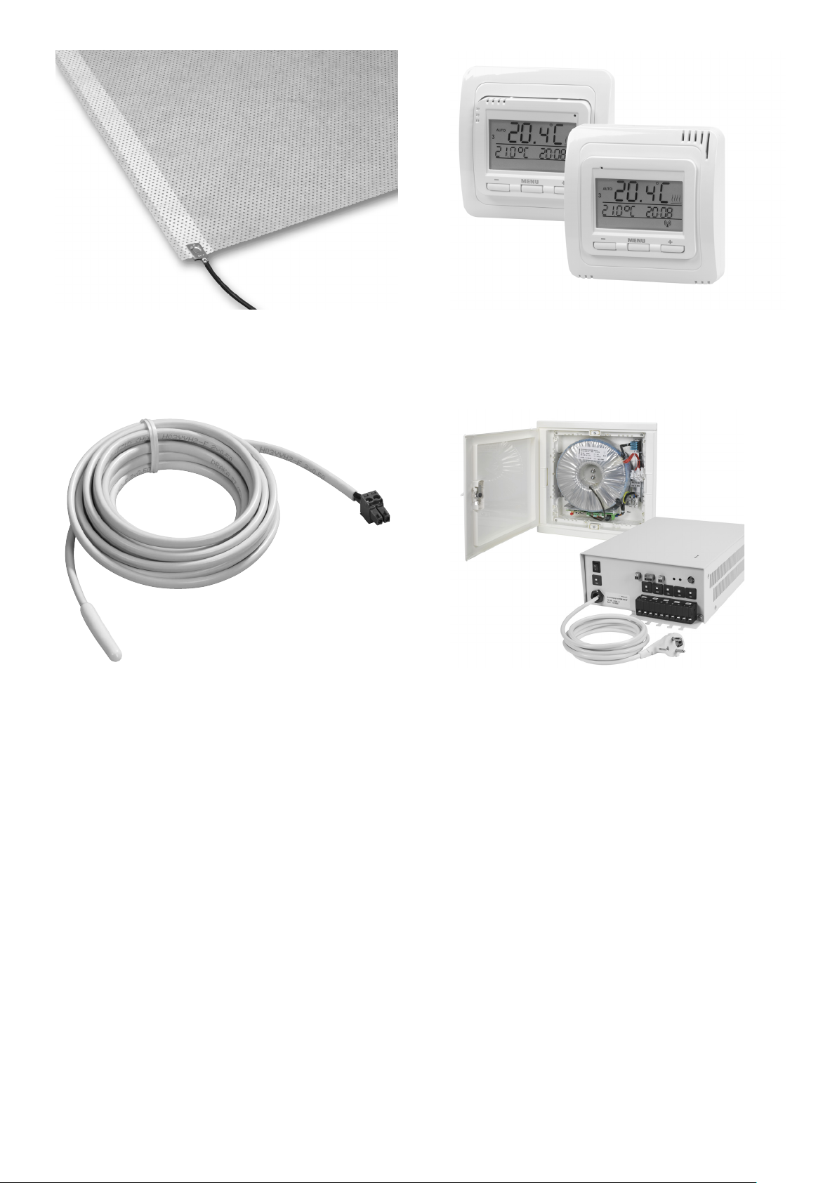
Heizfolie konfektioniert, ....
Heating package: film, ...
... Temperaturregler, ...
... temperature controller, ...
... Temperaturfühler, ...
... temperature sensor, ...
... und Netzteil hicoTHERM® Unterputz (bis 1600 W),
Netzteil hicoTHERM® Aufputz (bis 2000 W).
... power supply unit flush-mounted (up to 1,600 W),
power supply unit surface-mounted (up to 2,000 W).
15
Page 16
Artikel-Nummer: / Article number: 0906205808
Technische Änderungen vorbehalten. / Subject to technical amendment.
FZ/3/03.18/005/FZ
Frenzelit GmbH
P.O. Box 11 40 • 95456 Bad Berneck • Germany
Phone: +49 9273 72-111 • Fax: +49 9273 72-8111
info@hicotherm.com
 Loading...