

Frenic 5000VG7S Series Instruction Manual
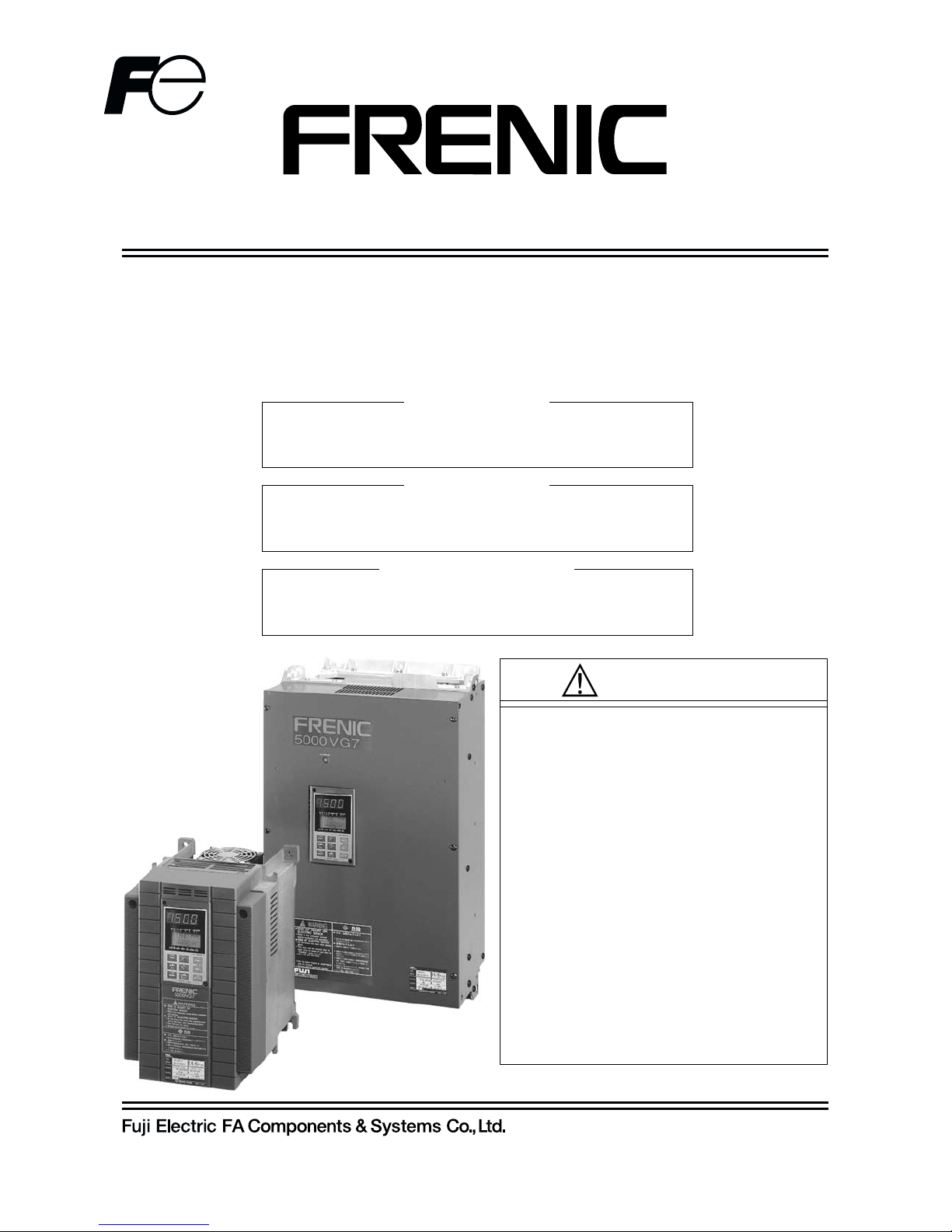
5000VG7S Series
INSTRUCTION MANUAL
High-Performance, Vector Control Inverter
INR-HF51306c-E
CT Use (150%)
VT Use (110%)
HT Use (200%/170%)
200V Series
0.75kW/FRN0.75VG7S-2
〜90kW/FRN90VG7S-2
400V Series
3.7kW/FRN3.7VG7S-4
〜400kW/FRN400VG7S-4
200V Series
1.5kW/FRN0.75VG7S-2
〜110kW/FRN90VG7S-2
400V Series
5.5kW/FRN3.7VG7S-4
〜500kW/FRN400VG7S-4
200V Series
3.7kW/FRN3.7VG7S-2
〜55kW/FRN55VG7S-2
400V Series
3.7kW/FRN3.7VG7S-4
〜55kW/FRN55VG7S-4
■Read all operating instructions
before installing, connecting
(wiring), operating, servicing, or
inspecting the inverter.
■Ensure that this instruction manual
is made available to the final user
of the inverter.
■Store this manual in a safe,
convenient location.
■The product is subject to change
without prior notice.
CAUTION
0-1
Instructions
Thank you for purchasing our FRENIC5000VG7S series inverter. This product is used to drive a 3-phase
induction motor at variable speed. As incorrect use of this product may result in personal injury and/or
property damage, read all operating instructions before using.
As this manual does not cover the use of function cords and option cards, etc., refer to FRENIC5000VG7S
Users Manual.
Safety Instructions
Read this manual carefully before installing, connecting (wiring), operating, servicing, or inspecting the inverter.
Familiarize yourself with all safety features before using the inverter.
In this manual, safety messages are classified as follows:
Improper operation may result in serious personal injury or death.
Improper operation may result in slight to medium personal injury or
property damage.
Situations more serious than those covered by CAUTION will depend on prevailing circumstances.
Always follow instructions.
Instructions on use
· This inverter is designed to drive a 3-phase induction motor and is not suitable for a single-phase motor or
others, as fire may result.
· This inverter may not be used (as is) as a component of a life-support system or other medical device
directly affecting the personal welfare of the user.
· This inverter is manufactured under strict quality control standards. However, safety equipment must be
installed if the failure of this device may result in personal injury and/or property damage.
There is a risk of accident.
Instructions on installation
· Mount this inverter on an incombustible material such as metal.
There is a risk of fire.
· Do not place combustible or flammable material near this inverter, as fire may result.
· The inverter housed in IP00 (18.5kW or over) should be installed in a place where no one can touch it
easily.
Electric shock or injury may result.
0-2
· Do not hold or carry this inverter by the surface cover. Inverter may be dropped causing injury.
· Ensure that the inverter and heat sink surfaces are kept free from foreign matter (lint, paper dust, small
chips of wood or metal chips), as fire or accident may result.
· Do not install or operate a damaged inverter or an inverter with missing parts, as injury may result.
· When changing installation bracket position, use the attached screws, as injury may result.
Instructions on wiring
· Confirm that the phases and rated voltage of this product match those of the AC power supply, as injury
may result.
· Do not connect the AC power supply to the output terminals (U, V, and W), as injury may result.
· Do not connect a braking resistor directly to the DC terminals (P(+) and N(-)), as fire may result.
· When using DC power input, ensure that the fan power switching connector (CN RXTX) is correctly
engaged in the inverter as a trouble may occur.
· When using DC power input of 18.5kW or larger inverter, be sure to connect AC power to terminals R0
and T0 for a power supply of fan as a trouble may occur.
· Ensure that the noise generated by the inverter, motor, or wiring does not adversely affect peripheral
sensors and equipment, as accident may result.
0-3
Instructions on operation
· Be sure to install the surface cover before turning on the power (closed). Do not remove the cover while
power to the inverter is turned on.
Electric shock may occur.
· Do not operate switches with wet hands, as electric shock may result.
· When the retry function is selected, the inverter may restart automatically after tripping. (Design the
machine to ensure personal safety in the event of restart)
Accident may result.
· When the torque limiting function is selected, operating conditions may differ from preset conditions
(acceleration/deceleration time or speed). In this case, personal safety must be assured.
Accident may result.
· As the STOP key is effective only when a function setting has been established, install an emergency
switch independently, and when an operation via the external signal terminal is selected, the STOP key
on the KEYPAD panel will be disabled.
Accident may result.
· As operations start suddenly if alarm is reset with a running signal input, confirm that no running signal is
input before resetting alarm.
Accident may result.
· When an alarm is activated, the motor coasts. If the motor needs to be stopped in such a case, install a
brake to the machine with the motor.
Accident may result.
· If AUTO RESTART is selected in the restart mode after momentary power failure (function code F14), the
inverter restarts automatically starting the motor rotation when the power is recovered.
Accident may result.
· When the tuning (function code H01) is started, the motor, machine or equipment starts and stops
repeatedly. Ensure safety before performing tuning.
Accident may result.
· If the user set the function codes wrongly or without completely understanding this user’s manual, the
motor may rotate with a torque or at a speed not permitted for the machine.
Accident or injury may result.
· Do not touch inverter terminals when energized even if inverter has stopped.
Electric shock may result.
· Do not start or stop the inverter using the main circuit power.
Failure may result.
· Do not touch the heat sink or braking resistor because they become very hot.
Burns may result.
· As the inverter can set high speed operation easily, carefully check the performance of motor or machine
before changing speed settings.
Injury may result.
· Do not use the inverter braking function for mechanical holding.
Injury may result.
· During pre-excitation, the speed adjuster does not function and the motor may be rotated by load
disturbance. When using pre-excitation, therefore, also use the mechanical brake.
Injury may result.
· If improper data is set at the function code related with speed adjuster as in the case of setting high gain
abruptly, the motor may hunt.
Injury may result.
0-4
Instructions on maintenance, inspection, and replacement
· Wait a minimum of five minutes (15kW or less) or ten minutes (18.5kW or more) after power has been
turned off (open) before starting inspection. (Also confirm that the charge lamp is off and that DC voltage
between terminals P(+) and N(-) does not exceed 25V.)
Electric shock may result.
· Only authorized personnel should perform maintenance, inspection, and replacement operations.
(Take off metal jewelry, such as watches and rings. Use insulated tools.)
Electric shock or injury may result.
Instructions on disposal
· Treat as industrial waste when disposing it.
Injury may result.
Other instructions
· Never modify the product.
Electric shock or injury may result.
General Instructions
Although figures in this manual may show the inverter with covers and safety screens removed for
explanation purposes, do not operate the device until all such covers and screens have been replaced.
0-5
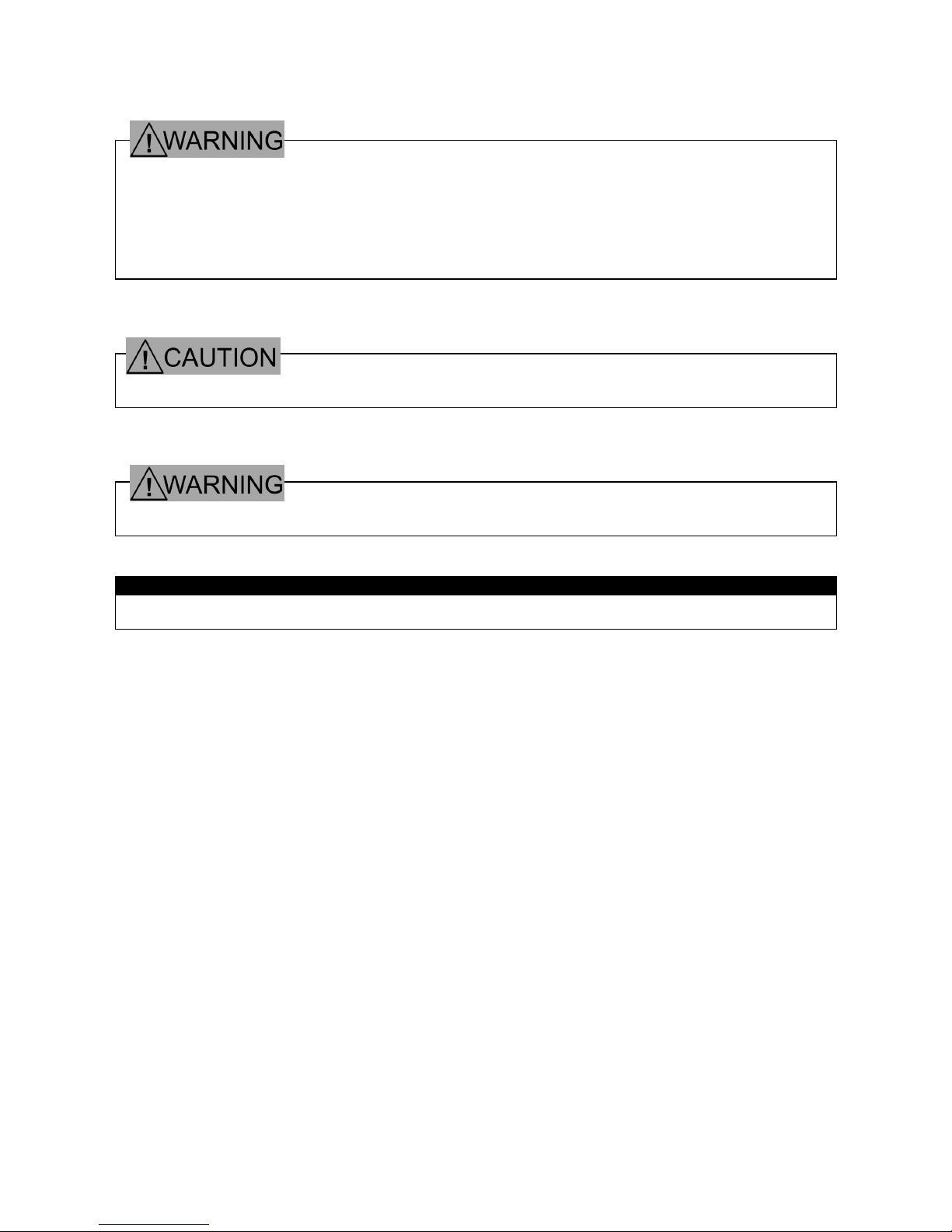
Warning Label Position
Inverter with a small capacity (15kW or lower)
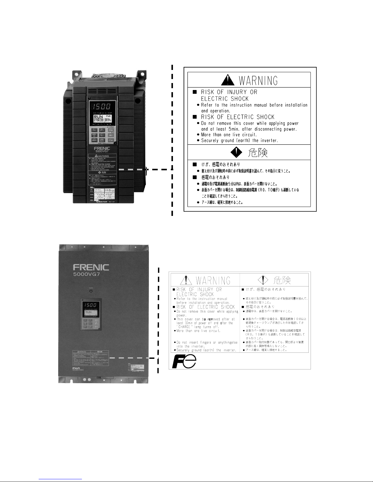
Inverter with a middle capacity (18.5kW or higher)
0-6
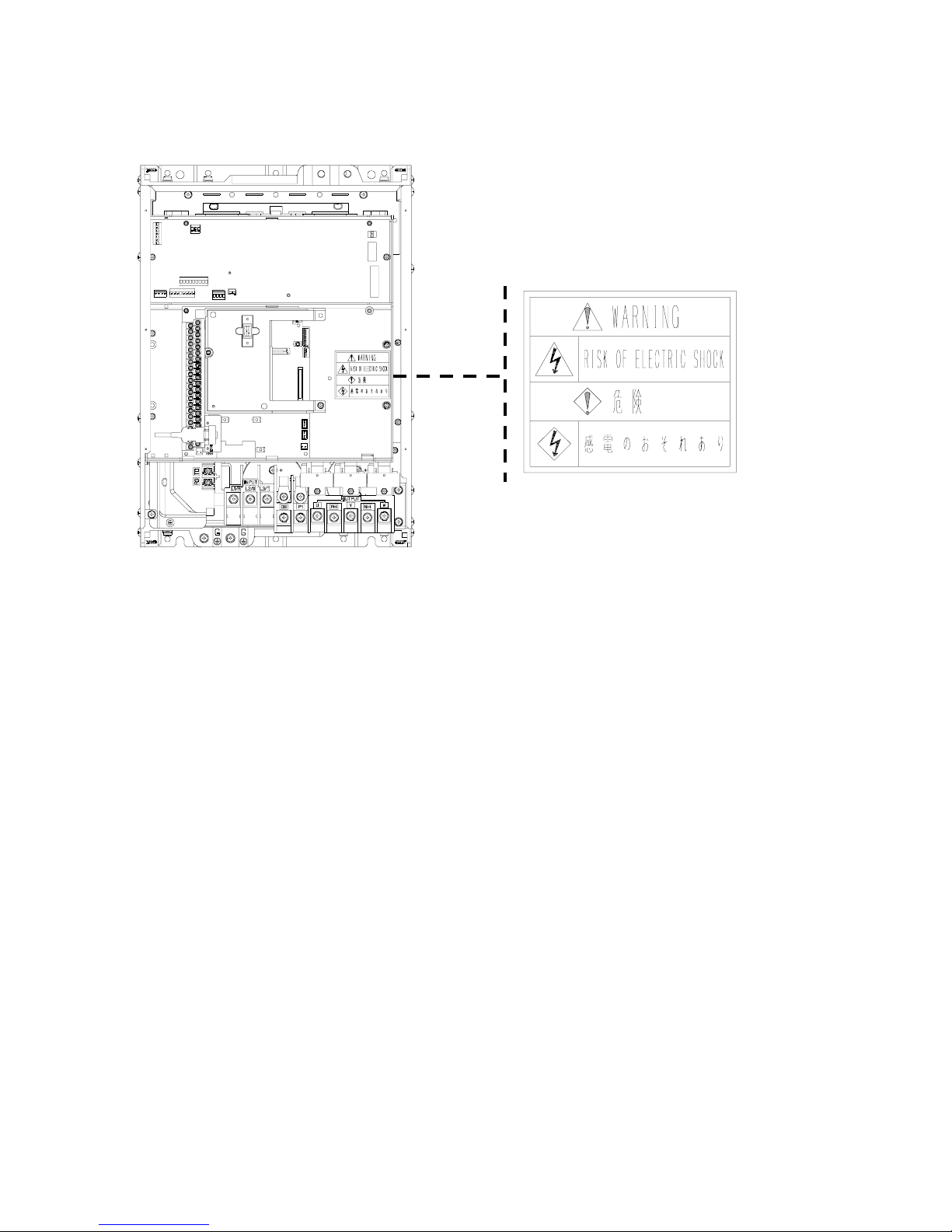
Warning Label Position for Inside the Inverter

0-7
Compliance with UL/cUL Standards
1. Overview
The UL standard is an abbreviation for Underwriters Laboratories Inc. and is a safety standard for preventing
fires and other accidents, and protecting users, servicemen, and general people in the United States.
The cUL standard is a standard which the UL constituted to meet the CSA standard. Products approved by
the cUL standard are as valid as produces approved by the CSA standard.
2. Notes
See the following notes when you use your inverters as UL/cUL approved products.
CAUTION for UL/cUL requirements
・Hazard of electrical shock. Disconnect incoming power before working on this control.
・Dangerous voltage exists until charge lights is off.
・More than one live circuit.
・Use 60/75℃ or 90℃ copper wire only.
・A Class 2 circuit wired with class1 wire.
・Field wiring connection must be made by a UL Listed and CSA Certified closed-loop terminal
connector sized for the wire gauge involved. connector must be fixed using the crimp tool
specified by the connector manufacturer.
・Connect the power supply to main power supply terminals via the Molded-case circuit
breaker(MCCB) or the earth leakage circuit breaker(ELCB) to apply the UL Listing Mark.
(See Instruction Manual basic connection diagram Fig.2-3-1).
・In case of using auxiliary control-power input (R0,T0), connect it referring to Instruction Manual Basic
connection diagram Fig.2-3-1.
・Solid state motor overload protection is provided in each model.
See Users Manual : MHT263□ for details.
0-8
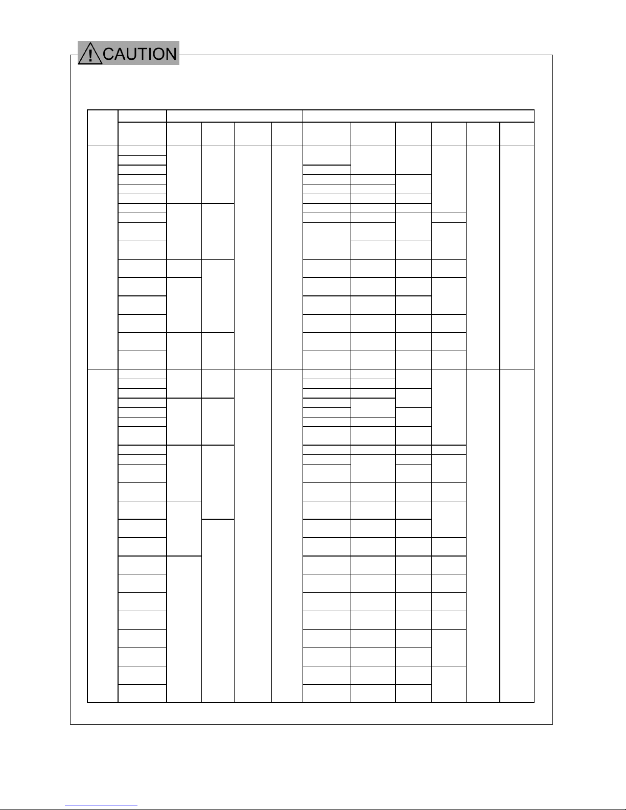
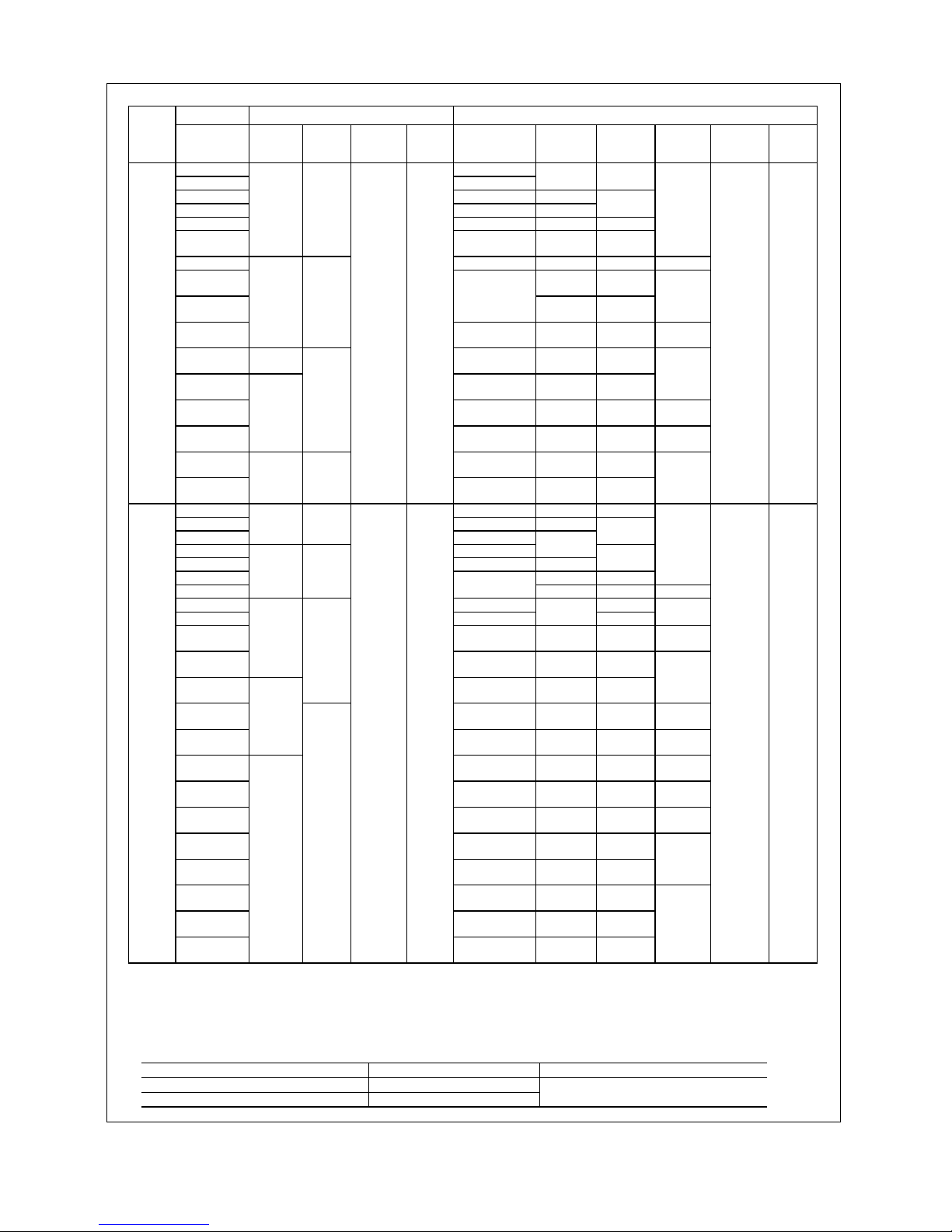
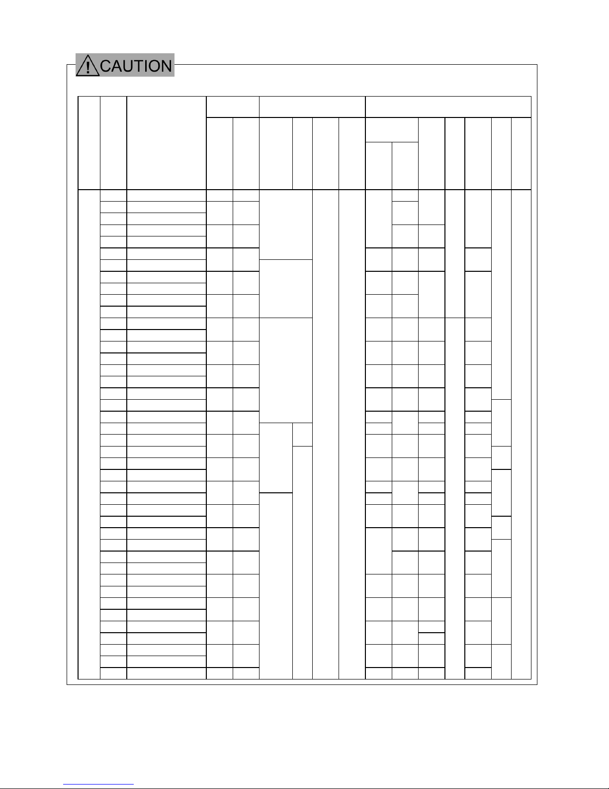
Tightening torque and wire range
1. 60℃/75℃ copper wire
CT/HT Use
Inverter type Required torque [lb-inch](N.m) Wire range [AWG] (mm2)
Voltage
FRN□
VG7S-2/4
Main
terminal
Ground
Auxiliar
y
control-
p
owe
r
Control
L1/R,L2/S,
L3/T
U,V,W P1,P(+
)
P(+),DB,
N(-)
Auxiliar
y
control-
p
owe
r
Control
0.75
1.5
14
(2.1)
2.2 12 (3.3)
14
(2.1)
14
(2.1)
3.7 8 (8.4) 10 (5.3)
5.5 6 (13.3) 8 (8.4)
10
(5.3)
7.5
31.0
(3.5)
31.0
(3.5)
8X2 (8.4X2) 6 (13.3) 6 (13.3)
11 6X2 (13.3X2) 4 (21.2) 4 (21.2)
14
(2.1)
15 4X2 (21.2X2) 3 (26.7) 12 (3.3)
18.5
6X2
(13.3X2)
3
(26.7)
22
51.3
(5.8)
51.3
(5.8)
3X2
(26.7X2)
4X2
(21.2X2)
4X2
(21.2X2)
10
(5.3)
30
119
(13.5)
2X2
(33.6X2)
1/0
(53.5)
3X2
(26.7X2)8(8.4)
37
1X2
(42.4X2)
3/0
(85)
4/0
(107.2)
45
2/0X2
(67.4X2)
4/0
(107.2)
1X2
(42.4X2)
6
(13.3)
55
239
(27)
119
(13.5)
3/0X2
(85X2)
1/0X2
(53.5X2)
2/0X2
(67.4X2)4 (21.2)
75
2/0X2
(67.4x2)
3/0X2
(85X2)
4/0X2
(107.2X2)2(33.6)
3-
Phase
200V
90
425
(48)
239
(27)
10. 6
(1.2)
6. 2
(0.7)
600
(304)
4/0X2
(107.2X2)
250X2
(127X2)1(42.4)
16
(1.3)24(0.2)
3.7 12 (3.3) 14 (2.1)
5.5 10 (5.3) 12 (3.3)
14
(2.1)
7.5
31. 0
(3.5)
31. 0
(3.5)
8 (8.4) 10 (5.3)
11 6 (13.3)
10
(5.3)
15 4 (21.2)
8
(8.4)
18.5 3 (26.7) 6(13.3)
6
(13.3)
22
51. 3
(5.8)
51. 3
(5.8)
6X2
(13.3X2)
4 (21.2) 4 (21.2)
14
(2.1)
30 2 (33.6) 3 (26.7) 3 (26.7) 12(3.3)
37 1 (42.4) 2 (33.6)
45
3X2
(26.7X2)
2
(33.6)
1
(42.4)
10
(5.3)
55
119
(13.5)
2X2
(33.6X2)
1/0
(53.5)
3X2
(26.7X2)8(8.4)
75
119
(13.5)
2/0
(67.4)
3/0
(85)
4/0
(107.2)
90
3/0
(85)
4/0
(107.2)
1X2
(42.4X2)
6
(13.3)
110
239
(27)
1X2
(42.4X2)
1/0X2
(53.5X2)
1/0X2
(53.5X2)4(21.2)
132
350
(177)
400
(203)
3/0X2
(85X2)3(26.7)
160
3/0X2
(85X2)
3/0X2
(85X2)
4/0X2
(107.2x2)2(33.6)
200
4/0X2
(107.2X2)
250X2
(127X2)
300X2
(152X2)
1/0
(53.5)
220
250X2
(127X2)
300X2
(152X2)
350X2
(177X2)
2/0
(67.4)
280
400X2
(203X2)
400X2
(203X2)
250X3
(127X3)
315
250X3
(127X3)
250X3
(127X3)
300X3
(152X3)
3/0
(85)
355
600X2
(304X2)
600X2
(304X2)
400X3
(203X3)
3-
Phase
400V
400
425
(48)
239
(27)
10. 6
(1.2)
6. 2
(0.7)
350X3
(177X3)
350X3
(177X3)
500X3
(253X3)
250
(127)
16
(1.3)24(0.2)
0-9
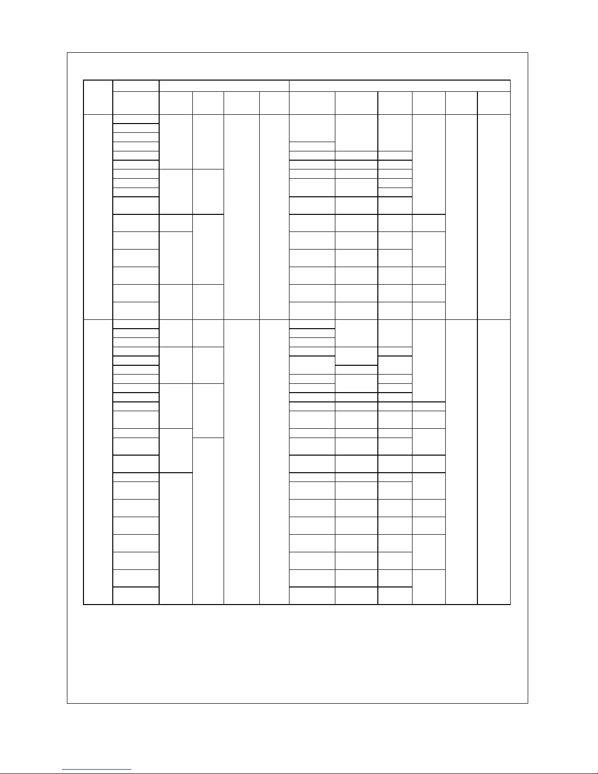
VT Use
Inverter type Required torque [lb-inch](N.m) Wire range [AWG] (mm2)
Voltage
FRN□
VG7S-2/4
Main
terminal
Ground
Auxiliar
y
control-
powe
r
Control
L1/R,L2/S,
L3/T
U,V,W P1,P(+
)
P(+),DB,
N(-)
Auxiliar
y
control-
powe
r
Control
0.75 14 (2.1)
1.5 12 (3.3)
14
(2.1)
14
(2.1)
2.2 8 (8.4) 10 (5.3
)
3.7 6 (13.3) 8 (8.4)
10
(5.3)
5.5 8X2 (8.4X2)6 (13.3)6 (13.3
)
7.5
31. 0
(3.5)
31. 0
(
3.5
)
6X2
(13.3X2)
8X2
(
8.4X2
)
10X2
(
5.3X2
)
14
(2.1)
11 4X2 (21.2X2)3 (26.7)3 (26.7)12 (3.3
)
15
6X2
(
13.3X2
)
6X2
(
13.3X2
)
18.5
3X2
(26.7X2)
4X2
(
21.2X2
)
4X2
(
21.2X2
)
10
(5.3)
22
51. 3
(5.8)
51. 3
(
5.8
)
3X2
(26.7X2)
3X2
(
26.7X2
)
3X2
(
26.7X2
)
8
(8.4)
30
119
(
13.5
)
1X2
(42.4X2)
2X2
(
33.6X2
)
2X2
(
33.6X2
)
37
2/0X2
(67.4X2)
4/0
(
107.2
)
1X2
(
42.4X2
)
6
(
13.3
)
45
3/0X2
(85X2)
1/0X2
(
53.5X2
)
2/0X2
(
67.4X2
)
4
(
21.2
)
55
239
(27)
119
(
13.5
)
2/0X2
(67.4X2)
3/0X2
(
85X2
)
4/0X2
(
107.2X2
)
2
(
33.6
)
75
4/0
(107.2X2)
4/0X2
(
107.2X2
)
250X2
(
127X2
)
3-
Phase
200V
90
425
(48)
239
(27)
10. 6
(1.2)
6. 2
(
0.7
)
250X2
(127X2)
300X2
(
152X2
)
350X2
(
177X2
)
1
(
42.4
)
16
(1.3)
24
(
0.2
)
3.7 10 (5.3) 12 (3.3)14 (2.1
)
5.5 8 (8.4) 10 (5.3
)
7.5
31. 0
(3.5)
31. 0
(
3.5
)
6 (13.3)
10
(5.3)
11 4 (21.2)
8
(8.4)
15 3 (26.7) 6 (13.3
)
6
(13.3)
18.5 4 (21.2)4 (21.2
)
14
(2.1)
22
51. 3
(5.8)
51. 3
(
5.8
)
6X2
(13.3X2)
3
(
26.7)3 (26.7)12 (3.3
)
30 1 (42.4) 2 (33.6
)
37 3X2(26.7X2
)
2
(33.6)
1
(
42.4
)
10
(5.3)
45
2X2
(33.6X2)
1/0
(53.5)
3X2
(
26.7X2
)
8
(8.4)
55
119
(
13.5
)
3X2
(26.7X2)
2X2
(
33.6X2
)
2X2
(
33.6X2
)
75
119
(
13.5
)
3/0
(85)
4/0
(
107.2
)
1X2
(
42.4X2
)
6
(
13.3
)
90
1X2
(42.4X2)
1/0X2
(
53.5X2
)
1/0X2
(
53.5X2
)
4
(
21.2
)
110
239
(27)
1/0X2
(53.5X2)
2/0X2
(
67.4X2
)
3/0X2
(
85X2
)
3
(
26.7
)
132
3/0X2
(85X2)
3/0X2
(
85X2
)
4/0X2
(
107.2X2
)
2
(
33.6
)
160
4/0X2
(107.2X2)
250X2
(
127X2
)
300X2
(
152X2
)
1/0
(
53.5
)
200
250X2
(127X2)
300X2
(
152X2
)
350X2
(
177X2
)
2/0
(
67.4
)
220
350X2
(177X2)
400X2
(
203X2
)
500X2
(
253X2
)
280
4/0X3
(107.2X3)
250X3
(
127X3
)
300X3
(
152X3
)
3/0
(85)
315
300X3
(152X3)
300X3
(
152X3
)
400X3
(
203X3
)
355
350X3
(177X3)
350X3
(
177X3
)
500X3
(
253X3
)
3-
Phase
400V
400
425
(48)
239
(27)
10. 6
(1.2)
6. 2
(
0.7
)
500X3
(253X3)
600X3
(
304X3
)
600X3
(
304X3
)
250
(127)
16
(1.3)
24
(
0.2
)
・ “Suitable for use on a circuit capable or delivering not more than 42,000 rms symmetrical amperes, 230V maximum”
rated for 200V class input.
・ “Suitable for use on a circuit capable or delivering not more than 42,000 rms symmetrical amperes, 480V maximum”
rated for 400V class input.
Connect power supplies described in the following table as the input power supply for your inverters. (short circuit standard)
Inverter model Maximum input voltage Input power supply current
FRN0.75VG7S-2 - FRN90VG7S-2 AC230V
FRN3.7VG7S-4 - FRN400VG7S-4 AC480V
42,000A or less
0-10
2. 90℃ copper wire
CT/HT Use
Inverter type Required torque [lb-inch](N.m) Wire range [AWG] (mm2)
Voltage
FRN□
VG7S-2/4
Main
terminal
Ground
Auxiliar
y
control-
p
owe
r
Control
L1/R,L2/S,
L3/T
U,V,W P1,P(+
)
P(+),DB,
N(-)
Auxiliar
y
control-
p
owe
r
Control
0.75
1.5
2.2
14 (2.1)
3.7 10 (5.3)
14 (2.1) 14 (2.1)
5.5 8 (8.4) 10 (5.3) 12 (3.3)
7.5
31. 0
(3.5)
31. 0
(3.5)
6 (13.3) 8 (8.4) 8 (8.4)
11 3 (26.7) 6 (13.3) 6 (13.3)
15 4 (21.2)
18.5
6X2
(13.3X2)
4 (21.2)
3 (26.7)
22
51. 3
(5.8)
51. 3
(5.8)
4X2
(21.2X2)
6X2
(13.3X2)
6X2
(13.3X2)
14 (2.1)
30
119
(13.5)
3X2
(26.7X2)
1
(42.4)
1/0
(53.5)10(5.3)
37
4/0
(107.2)
2/0
(67.4)
3/0
(85)
45
1/0X2
(53.5X2)
3/0
(85)
4/0
(107.2)
8
(8.4)
55
239
(27)
119
(13.5)
2/0X2
(67.4X2)
1X2
(42.4X2)
1/0X2
(53.5X2)6(13.3)
75
350
(177)
400
(203)
3/0X2
(85X2)4(21.2)
3-
Phase
200V
90
425
(48)
239
(27)
10. 6
(1.2)
6. 2
(0.7)
500
(253)
600
(304)
4/0X2
(107.2X2)2(33.6)
16
(1.3)24(0.2)
3.7 14 (2.1)
5.5 12 (3.3)
7.5
31. 0
(3.5)
31. 0
(3.5)
10 (5.3)
14 (2.1) 14 (2.1)
11 8 (8.4) 12 (3.3)
15
10 (5.3)
18.5
6 (13.3)
8 (8.4)
8 (8.4)
22
51. 3
(5.8)
51. 3
(5.8)
4 (21.2) 6 (13.3)
30 3 (26.7)
6 (13.3)
4 (21.2)
37 2 (33.6) 4 (21.2) 3 (26.7)
14 (2.1)
45 1/0 (53.5) 2 (33.6) 2 (33.6) 12 (3.3)
55
119
(13.5)
4X2
(21.2X2)
1
(42.4)
1/0
(53.5)10(5.3)
75
119
(13.5)
1/0 (53.5) 2/0 (67.4) 3/0 (85)
90 3/0 (85) 3/0 (85)
4/0
(107.2)
8
(8.4)
110
239
(27)
4/0
(107.2)
1X2
(42.4X2)
1X2
(42.4X2)6(13.3)
132 250 (127) 300 (152) 400(203)
160
400
(203)
400
(203)
3/0X2
(85X2)
4
(21.2)
200
600
(304)
600
(304)
250X2
(127X2)1(42.4)
220
4/0X2
(107.2X2)
4/0X2
(107.2X2)
300X2
(152X2)
1/0
(53.5)
280
300X2
(152X2)
350X2
(177X2)
400X2
(203X2)
315
350X2
(177X2)
400X2
(203X2)
500X2
(253X2)
2/0
(67.4)
355
500X2
(253X2)
500X2
(253X2)
300X3
(152X3)
3-
Phase
400V
400
425
(48)
239
(27)
10. 6
(1.2)
6. 2
(0.7)
600X2
(304X2)
600X2
(304X2)
400X3
(203X3)
4/0
(107.2)
16
(1.3)24(0.2)
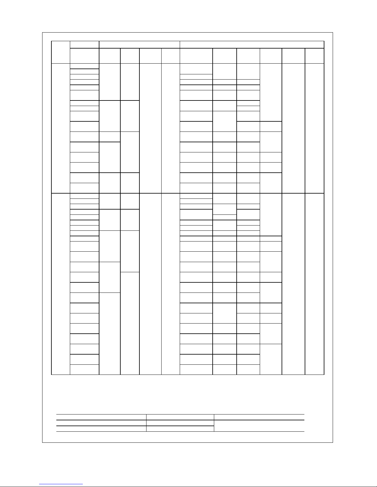
0-11
VT Use
Inverter type Required torque [lb-inch](N.m) Wire range [AWG] (mm2)
Voltage
FRN□
VG7S-2/4
Main
terminal
Ground
Auxiliar
y
control-
powe
r
Control
L1/R,L2/S,
L3/T
U,V,W P1,P(+
)
P(+),DB,
N(-)
Auxiliar
y
control-
powe
r
Control
0.75
1.5
14 (2.1)
2.2 10 (5.3)
14
(
2.1)14 (2.1
)
3.7 8 (8.4) 10 (5.3)12 (3.3
)
5.5 6 (13.3) 8 (8.4) 8 (8.4
)
7.5
31. 0
(3.5)
31. 0
(
3.5
)
8X2
(8.4X2)
6
(13.3)6(13.3)
11 4 (21.2
)
15
6X2
(13.3X2)
4
(21.2)
3 (26.7
)
18.5
4X2
(21.2X2)
6X2
(
13.3X2
)
14
(2.1)
22
51. 3
(5.8)
51. 3
(
5.8
)
3X2
(26.7X2)
6X2
(
13.3X2
)
4X2
(
21.2X2
)
10
(5.3)
30
119
(
13.5
)
2X2
(33.6X2)
4x2
(
21.2x2
)
3X2
(
26.7X2
)
37
1/0X2
(53.5X2)
3/0
(85)
4/0
(
107.2
)
8
(8.4)
45
2/0X2
(67.4X2)
1x2
(
42.4x2
)
1/0X2
(
53.5X2
)
6
(
13.3
)
55
239
(27)
119
(
13.5
)
1/0X2
(53.5X2)
2/0X2
(
67.4X2
)
3/0X2
(
85X2
)
4
(
21.2
)
75
3/0X2
(85X2)
3/0X2
(
85X2
)
4/0X2
(
107.2
)
3-
Phase
200V
90
425
(48)
239
(27)
10. 6
(1.2)
6. 2
(
0.7
)
4/0X2
(107.2X2)
4/0X2
(
107.2X2
)
300X2
(
152X2
)
2
(
33.6
)
16
(1.3)
24
(
0.2
)
3.7 12 (3.3)
5.5 10 (5.3)
14
(
2.1)14 (2.1
)
7.5
31. 0
(3.5)
31. 0
(
3.5
)
8 (8.4) 12 (3.3
)
11
10
(
5.3
)
15
6 (13.3)
8 (8.4)
8
(
8.4
)
18.5 4 (21.2) 6 (13.3
)
22
51. 3
(5.8)
51. 3
(
5.8
)
3 (26.7)
6
(
13.3
)4 (
21.2
)
30 2 (33.6) 4 (21.2)3 (26.7
)
14
(2.1)
37 1/0 (53.5) 2 (33.6)2 (33.6)12 (3.3
)
45
4X2
(21.2X2)
1
(42.4)
1/0
(53.5)10(5.3)
55
119
(
13.5
)
1/0
(53.5)
4X2
(
21.2X2
)
3X2
(
26.7X2
)
75
119
(
13.5
)
3/0
(85)
3/0
(85)
4/0
(
107.2
)
8
(8.4)
90
4/0
(107.2)
1X2
(
42.4X2
)
1X2
(
42.4X2
)
6
(
13.3
)
110
239
(27)
1X2
(42.4X2)
1/0X2
(
53.5X2
)
2/0X2
(
67.4X2
)
132
400
(203)
400
(203)
3/0X2
(
85X2
)
4
(
21.2
)
160
3/0X2
(85X2)
250X2
(
127X2
)
1
(
42.4
)
200
4/0X2
(107.2X2)
4/0X2
(
107.2X2
)
300X2
(
152X2
)
1/0
(
53.5
)
220
300X2
(152X2)
350X2
(
177X2
)
400X2
(
203X2
)
280
350X2
(177X2)
400X2
(
203X2
)
250X3
(
127X3
)
2/0
(
67.4
)
315
4/0X3
(107.2X3)
250X3
(
127X3
)
300X3
(
152X3
)
355
600X2
(304X2)
600X2
(
304X2
)
400X3
(
203X3
)
3-
Phase
400V
400
425
(48)
239
(27)
10. 6
(1.2)
6. 2
(
0.7
)
400X3
(203X3)
500X3
(
253X3
)
600X3
(
304X3
)
4/0
(
107.2
)
16
(1.3)
24
(
0.2
)
・ “Suitable for use on a circuit capable or delivering not more than 42,000 rms symmetrical amperes, 230V maximum”
rated for 200V class input.
・ “Suitable for use on a circuit capable or delivering not more than 42,000 rms symmetrical amperes, 480V maximum”
rated for 400V class input.
Connect power supplies described in the following table as the input power supply for your inverters. (short circuit standard)
Inverter model Maximum input voltage Input power supply current
FRN0.75VG7S-2 - FRN90VG7S-2 AC230V
FRN3.7VG7S-4 - FRN400VG7S-4 AC480V
42,000A or less
0-12
Compliance with European Standard
The CE marking presented on Fuji products is related to the Council Directive 89/336/EEC and the Low
Voltage Directive 73/23/EEC for the Electromagnetic Compatibility (EMC) in Europe.
Compliant standards
・・・・
EN 61800-3: 1997
・・・・
EN 50178: 1997
Only the models in the 400V series comply with the standards above among the "FRENIC5000 VG7S" series.
The 200V series do not conform to the standards. Please note that products of the CT/HT use 18.5 kW and
the VT use 22 kW do not comply with the standards, and if you need to use compliant products, you should
use the products of the CT/HT use 22 kW and the VT use 30 kW which are models with larger capacities by
one grade.
1. Compliance with Low Voltage Directive
1-1 Overview
Inverters are subject to the Low Voltage Directive in Europe. Fuji has obtained an approval for the compliance
from a European inspection organization, and voluntarily declares the compliance with the Low Voltage
Directive.
1-2 Notes
See the notes below when you use the inverters in your products compliant with the Low Voltage Directive in
Europe.
・ The contact capacity for the alarm relay output (30A, B, C) and the relay signal output (Y5A, Y5C) is DC
48V, 0.5A.
・ Connect your inverter to the ground securely.
・ Connect a ring terminal to a wire when you attach it to the main circuit and inverter ground terminals.
・ Use an independent wiring for the inverter ground terminal G. (Do not connect two or more wires)
・ When you use an earth leakage breaker (RCD), you can use only the Type B for protection for the power
supply.
Also you should use a transformer for double insulation or reinforced insulation to insulate your inverter
from the power supply.
・ Use a molded case circuit breaker (MCCB) and a magnetic contactor (MC) compliant with the EN or IEC
standard.
・ For a power supply system (I-T NET) where a neutral point is not grounded, the control terminals are
provided as basic insulation in respect to the main circuit. When a person may touch them directly, you
should add an external insulation circuit for double insulation.
・ Use your inverter under a condition corresponding to the overvoltage category III and the pollution degree 2
or more prescribed in the IEC664. Install your inverter in a control panel (IP54 or more) with a structure
preventing water, oil, carbon and dusts from entering for meeting the pollution degree 2 or more.
・ Use a wire with the diameter and the type prescribed in the Appendix C of the EN 60204 for the
input/output wiring for your inverter.
・ When you install an external heatsink which is a heatsink for inverter external to the control panel, you
should install a protection cover preventing a capacitor and a breaking resistor installed on the heatsink
from being touched.
・ When you install an optional AC reactor, a DC reactor, and an external braking resistor, follow the
description below to prevent an electric shock due to touching the terminals and active electrical parts.
1) Install them in a casing or wall of the IP4X when a person may have an easy access to them.
2) Install them in a casing or wall of the IP2X when a person does not have an easy access to them.
0-13
Table 1-2 Applicable main circuit motor/wire size for compliance to Low Voltage Directive(400V series)
Fuse/MCCB
Rated current [A]
Tightening torque [N.m] Recommended wire size [mm2]
L1/R,L2/SL3/T
( G)
Voltage
Applicable motor
KW
Inverter type
FRN□
With
DCR
Without
DCR
L1/R,L2/S,L3/T
U,V,W
P1,P(+),DB,N(-)
G
R0,T0
Controller
With
DCR
Without
DCR
U,V,W
R0,T0
P1,P(+)
P(+),DB,N(-)
Controller
3.7 3.7VG7S-4(CT/HT) 10 15 2.5
5.5 3.7VG7S-4(VT)
5.5 5.5VG7S-4(CT/HT)
15 20
4
(4)
2.5
7.5 5.5VG7S-4(VT)
7.5 7.5VG7S-4(CT/HT)
20 30
2.5
(2.5)
6
(6)4(4)
2.5
11 7.5VG7S-4(VT)
3.5
11 11VG7S-4(CT/HT)
30 40
4
(4)10(10)
66
15 11VG7S-4(VT)
15 15VG7S-4(CT/HT)
40 50 6
(6)16(16)
18.5 15VG7S-4(VT)
22 22VG7S-4(CT/HT)
40 60
5.8
10
25
(16)
10 10
30 22VG7S-4(VT)
30 30VG7S-4(CT/HT)
75 100 16
(16)
16X2
(16)
25 25
37 30VG7S-4(VT)
37 37VG7S-4(CT/HT)
100 125
25
(16)50(25)
35 35
45 37VG7S-4(VT)
45 45VG7S-4(CT/HT)
100 150 35
(25)
25X2
(25)
50 50
55 45VG7S-4(VT)
2.5
55 55VG7S-4(CT/HT)
125 175
50
(25)
35X2
(35)
25X2 25X2
75 55VG7S-4(VT)
13.5
25X2 35X2 35X2
75 75VG7S-4(CT)
175 -
70(35)
-
95 95
90 75VG7S-4(VT)
13.5
4
90 90VG7S-4(CT)
200 -
95
(50)
- 35X2 50X2
110 90VG7S-4(VT)
6
110 110VG7S-4(CT)
225 - 50X2
(50)
- 50X2 70X2
132 110VG7S-4(VT)
27
70X2 70X2 95X2
132 132VG7S-4(CT)
300 -
185
-
240 240
160 132VG7S-4(VT)
10
160 160VG7S-4(CT)
350 - 240
(120)
- 95X2 120X2
200 160VG7S-4(VT)
16
200 200VG7S-4(CT)
400 - - 120X2 150X2
220 200VG7S-4(VT)
220 220VG7S-4(CT)
500 -
120X2
(120)
- 150X2 185X2
280 220VG7S-4(VT)
280 280VG7S-4(CT)
600 -
185X2
(185)
- 240X2 240X2
25
315 280VG7S-4(VT)
315 315VG7S-4(CT)
700 - 240X2
(240)
- 240X2 185X3
355 315VG7S-4(VT) 150X3
355 355VG7S-4(CT)
800 -
240X2
(240)
-
300X2
185X3
50
400 355VG7S-4(VT)
400 400VG7S-4(CT)
1,000 - 185X3
(300)
- 185X3 240X3
400V
series
500 400VG7S-4(VT) 1,200 -
48
27
1.2 0.7
240X3 - 300X3
2.5
to
6
300X3
70
0.2
~
0.75
Note: The used wires are 600V PVC insulated electric wire with permissible temperature of 70°C.
This wire is selected assuming that the ambient temperature is 50° C or less.

0-14
Contents
Instructions
Safety Instructionss
1. Before Use ・・・・・・・・・・・・・・・・・・・・・・ 1-1
1-1 Inspection After Receipt ・・・・・・・・・・・・ 1-1
1-2 External View of the Product ・・・・・・・・ 1-1
1-3 Handling of the Product ・・・・・・・・・・・・ 1-2
1-4 Transportation ・・・・・・・・・・・・・・・・・・・・ 1-3
1-5 Storage ・・・・・・・・・・・・・・・・・・・・・・・・・・ 1-3
2. Installation and Connection ・・・・・ 2-1
2-1 Operating Conditions ・・・・・・・・・・・・・・ 2-1
2-2 Installation Procedure ・・・・・・・・・・・・・・ 2-2
2-3 Electric Connections ・・・・・・・・・・・・・・・ 2-4
2-3-1 Basic Connections ・・・・・・・・・・・ 2-4
2-3-2 Wiring of Main Circuit and
Grounding Terminals ・・・・・・・・・ 2-6
2-3-3 Wiring of Control
Terminals ・・・・・・・・・・・・・・・・・・・ 2-13
2-3-4 Terminal Arrangement Chart ・・ 2-17
3. Test Run ・・・・・・・・・・・・・・・・・・・・・・・・ 3-1
3-1 Preliminary Check and Preparation ・・ 3-1
3-2 Operating Methods ・・・・・・・・・・・・・・・・ 3-1
3-3 Test Run ・・・・・・・・・・・・・・・・・・・・・・・・・ 3-1
4. KEYPAD Panel ・・・・・・・・・・・・・・・・・・ 4-1
4-1 Appearance of KEYPAD Panel ・・・・・・ 4-1
4-2 Alarm Mode ・・・・・・・・・・・・・・・・・・・・・・ 4-3
4-3 KEYPAD Operation System
(Hierarchical Structure of
LCD Screens) ・・・・・・・・・・・・・・・・・・・・ 4-4
4-3-1 During Normal Operation ・・・・・ 4-4
4-3-2 When an Alarm
Raised Occurs ・・・・・・・・・・・・・・・ 4-4
4-3-3 Program Mode ・・・・・・・・・・・・・・ 4-6
5. Function Selection ・・・・・・・・・・・・・・ 5-1
6. List of Inverter Protective
Functions ・・・・・・・・・・・・・・・・・・・・・・・ 6-1
7. Function Description
(Arranged by Function) ・・・・・・・・・・ 7-1
7-1 If You Think Defective ・・・・・・・・・・・・・ 7-1
7-1-1 If You Think Defective ・・・・・・・・・ 7-1
7-1-2 What You Should Check First ・・ 7-1
7-2 Checks Using Flowchart ・・・・・・・・・・・ 7-3
7-2-1 Malfunctions not
Followed by Alarms ・・・・・・・・・・・ 7-3
7-2-2 Malfunctions Followed
Alarms ・・・・・・・・・・・・・・・・・・・・・・ 7-11
8. Maintenance and Inspection ・・・・ 8-1
8-1 Daily Inspection ・・・・・・・・・・・・・・・・・・・ 8-1
8-2 Periodical Inspection ・・・・・・・・・・・・・・ 8-1
8-3 Measurement of Main Circuit
Electrical Quantity ・・・・・・・・・・・・・・・・・ 8-4
8-4 Insulation Test ・・・・・・・・・・・・・・・・・・・・ 8-5
8-5 Parts Replacement ・・・・・・・・・・・・・・・・ 8-5
8-6 Inquiries about Products and
Product Guarantee ・・・・・・・・・・・・・・・・ 8-5
9. Compliance with Standards ・・・・ 9-1
9-1 Compliance with
UL/cUL Standards ・・・・・・・・・・・・・・・・ 9-1
9-1-1 Overview ・・・・・・・・・・・・・・・・・・・ 9-1
9-1-2 Notes ・・・・・・・・・・・・・・・・・・・・・・ 9-1
9-2 Compliance with
European Standard ・・・・・・・・・・・・・・・ 9-1
9-3 Compliance with Low
Voltage Directive ・・・・・・・・・・・・・・・・・ 9-1
9-3-1 Overview ・・・・・・・・・・・・・・・・・・・ 9-1
9-3-2 Notes ・・・・・・・・・・・・・・・・・・・・・・ 9-1
9-4 Compliance with EMC standard ・・・・・ 9-1
9-4-1 Overview ・・・・・・・・・・・・・・・・・・・ 9-1
9-4-2 RFI Filter ・・・・・・・・・・・・・・・・・・・ 9-1
9-4-3 Recommended Installation ・・・・ 9-1
1-1
1. Before Use
1-1 Inspection After Receipt
Unpackage the product and perform the following checks.
If the product is found to have a fault, please contact the dealer
from which you purchased the product or the nearest sales
office of Fuji Electric.
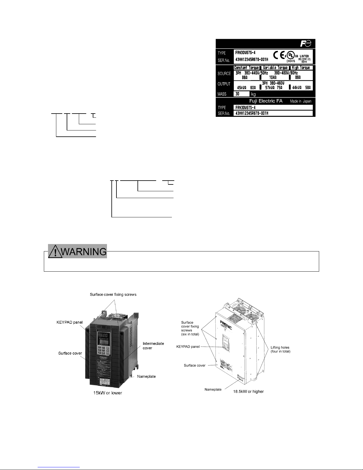
(1) Read the nameplate to check that the product is the same
thing as ordered.
TYPE : Inverter type
(2) Check for broken or missing parts and damage caused to the cover/body during transportation.
· Do not energize a product with broken or missing parts or damaged during transportation.
Doing so may lead to electric shock or fire.
1-2 External View of the Product
Voltage class: 2 for 200V or 4 for 400V
Series name: VG7S
Applicable motor capacity: 30 for 30kW
Model :FRENIC5000
FRN 30 VG7S - 4
Nameplate
SOURCE : Power ratings
OUTPUT : Rated output
MASS : Mass
SER.No. : Serial No.
4 3 HH12345R678 - 001H
Product No.
Serial lot No.
Month of manufacture:1 to 9 for January to
September, X for October,
Y for November,or Z for December
Year of manufacture:Last digit of A.D. (4 for 2004)
1-2
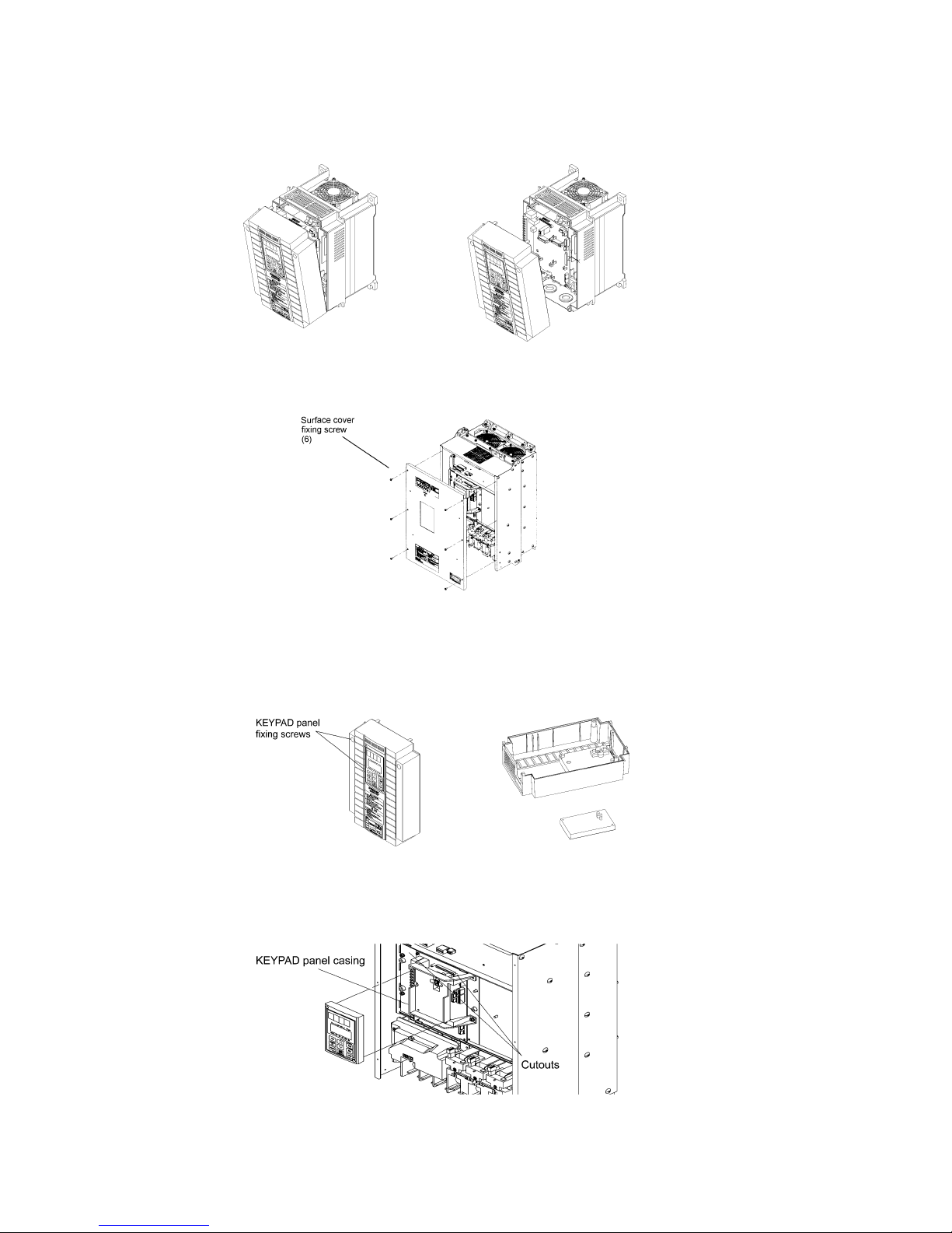
1-3 Handling of the Product
(1) Removal of Surface Cover
Loosen the surface cover fixing screws. Remove the cover by pulling the top of the cover as shown in
Figure 1-3-1.
Remove the six surface cover fixing screws. Remove the surface cover.
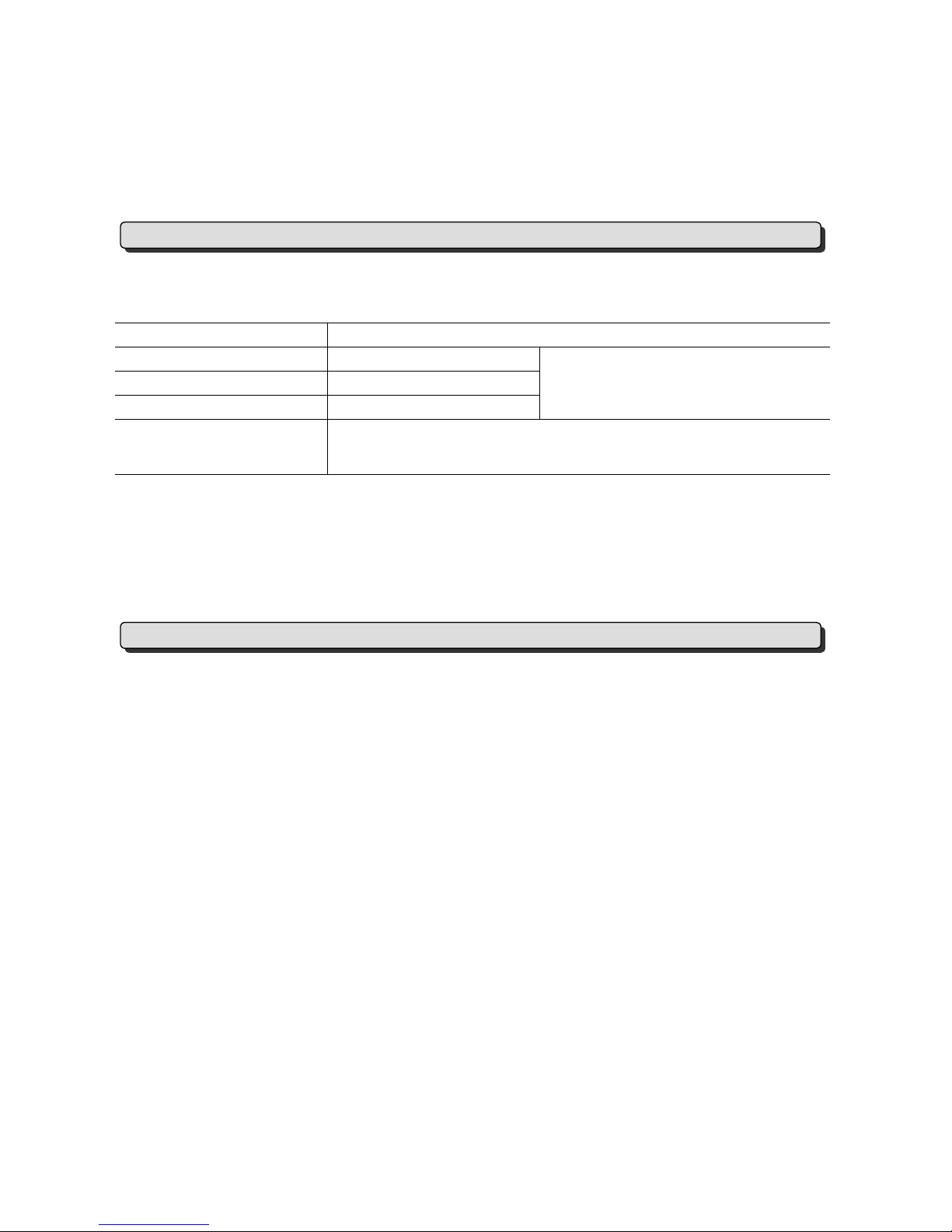
(2) Removal of KEYPAD Panel
After removing the face cover in step (1), loosen the KEYPAD panel fixing screws. Remove the KEYPAD
panel as shown in Figure 1-3-3.
Loosen the KEYPAD panel fixing screws. Carefully remove the KEYPAD panel with your fingers inserted
to the cutouts at the side of the KEYPAD panel. Careless handling may break connectors.
Figure 1-3-1 Removal of Surface Cover (15kW or lower)
Figure 1-3-2 Removal of Surface Cover (18.5kW or higher)
Figure 1-3-3 Removal of KEYPAD Panel (15kW or lower)
Figure 1-3-4 Removal of KEYPAD Panel (18.5kW or higher)
1-3
1-4 Transportation
Always hold the body during transportation.
Do not hold the cover or any other part. Doing so may break or fall the product.
When using a hoist or crane to transport a product with lifting holes, hang hooks and ropes to the holes.
1-5 Storage
Store the product under the conditions specified on Table 1-5-1.
Table 1-5-1 Storage Conditions
Item Requirement
Ambient temperature
-10 to +50°C
Storage temperature
See Note 1
-25 to +65°C
Relative humidity 5% to 95%
See Note 2
No condensation or freezing should occur
due to sudden temperature changes.
Atmosphere The product should not be exposed to dust, direct sunlight, corrosive or
combustible gas, oil mist, vapor, waterdrops, vibration, or air containing
much salt.
Note 1: The storage temperature applies to the temporary storage during transportation, for example.
Note 2: Do not store the product in a place where the temperature significantly changes as this may cause
condensation or freezing even if the humidity requirement is satisfied.
(1) Do not place the product directly on the floor.
(2) Pack the product with a plastic sheet or such if stored under undesirable conditions.
(3) Seal in a desiccative such as silica gel when packing the product if it may be affected by moisture.
The requirements to be satisfied when storing the product for an extended period after purchased greatly
depend on the environment. General requirements are listed below.
(1) Satisfy the requirements for temporary storage.
If the storage period exceeds three months, the ambient temperature should be kept below 30 °C to protect
the dead electrolytic capacitor from deterioration.
(2) Carefully pack the product to prevent the intrusion of moisture, etc. Seal in a desiccant to keep the relative
humidity inside the pack below 70%, as a guide.
(3) The product will be often exposed to moisture or dust if left mounted on a unit or console, especially in a
building under construction. In such a case, remove the product and relocate in a well-conditioned place.
The electrolytic capacitor will be deteriorated if left dead for an extended period. Do not leave it dead for a
period exceeding a year.
Temporary Storage
Extended Storage

2-1
2. Installation and Connection
2-1 Operating Conditions
Install the product under the conditions specified in Table 2-1-1.
Table 2-1-1 Operating Conditions
Item Requirement
Place Indoor
Ambient
temperature
-10 to +50°C
Relative humidity 5% to 95% (no condensation allowed)
Atmosphere
The product should not be exposed to dust, direct
sunlight, corrosive gas, oil mist, vapor, waterdrops, or
air containing much salt.
No condensation should occur due to sudden
temperature changes.
Altitude
1,000m or less (if more than 1,000m, see Table 2-1-
2)
2 to 9Hz: 3mm amplitude
9 to 20Hz: 9.8m/s
2
(or 2m/s2 for 200V, 75kW or
higher and 400V, 90kW or higher inverters)
Vibration
20 to 55Hz: 2m/s
2
55 to 200Hz: 1m/s
2
Table 2-1-2 Output Reduction Rates at Higher Altitudes
Altitude Output Current Reduction Rate
1,000m or less 1.00
1,000-1,500m 0.97
1,500-2,000m 0.95
2,000-2,500m 0.91
2,500-3,000m 0.88
2-2
2-2 Installation Procedure
(1) Install the product onto a rigid structure in the vertical direction with the letters, FRENIC5000 VG7S, seen
from the front and fix with specified bolts. Do not install upside down or in the horizontal direction.
Failure to do so may lead to injury.
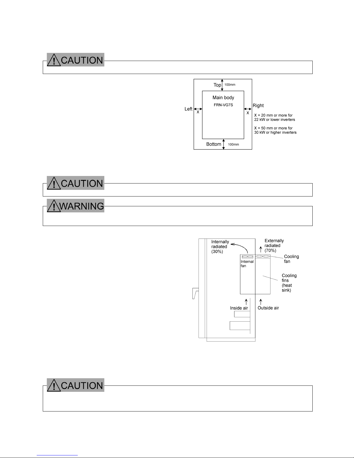
(2) The inverter generates heat during operation.
Reserve a space as shown in Figure 2-2-1 to ensure
a sufficient flow of cooling air. The heat is radiated
from the top. Do not install the inverter under any
unit susceptible to heat.
(3) The cooling fins (heat sink) are heated to almost 90°C during operation of the inverter. The inverter
mounting surface should be made of a material capable of withstanding this temperature rise.
The fins may burn your skin.
· Install the inverter onto an incombustible material such as metal.
Failure to do so may lead to fire.
(4) When storing the inverter in a control panel, for example,
sufficiently ventilate the inverter so that its ambient
temperature will not exceed the specified limit. Do not
store the inverter in a small closed box that does not
radiate heat well.
(5) When storing two or more inverters in a unit or control
panel, they are desirably arranged side by side to
minimize the thermal effect on each other. If they are
inevitably arranged with one above another, separating
plate should be provided to prevent the heat transfer
from the bottom side inverter to the above.
(6) The inverter is prepared to be mounted in a control
panel when delivered. It may be externally cooled
using the optional adapter if 15kW or lower or with the
mounting legs relocated if 18.5kW or higher.
With the inverter externally cooled, the heat generated
inside the unit or control panel is dissipated because the
cooling fins, which radiate 70% of the generated heat,
are excluded from the unit or control panel.
Do not exclude the cooling fins where they may be
clogged with lint or damp dust.
· Do not admit lint, paper, wooden chips, dust, metallic pieces, and any other foreign matters into the inverter
or allow them to stick to the cooling fins.
Doing so may lead to fire or accident.
Figure 2-2-1
Figure 2-2-2 External Cooling System
2-3
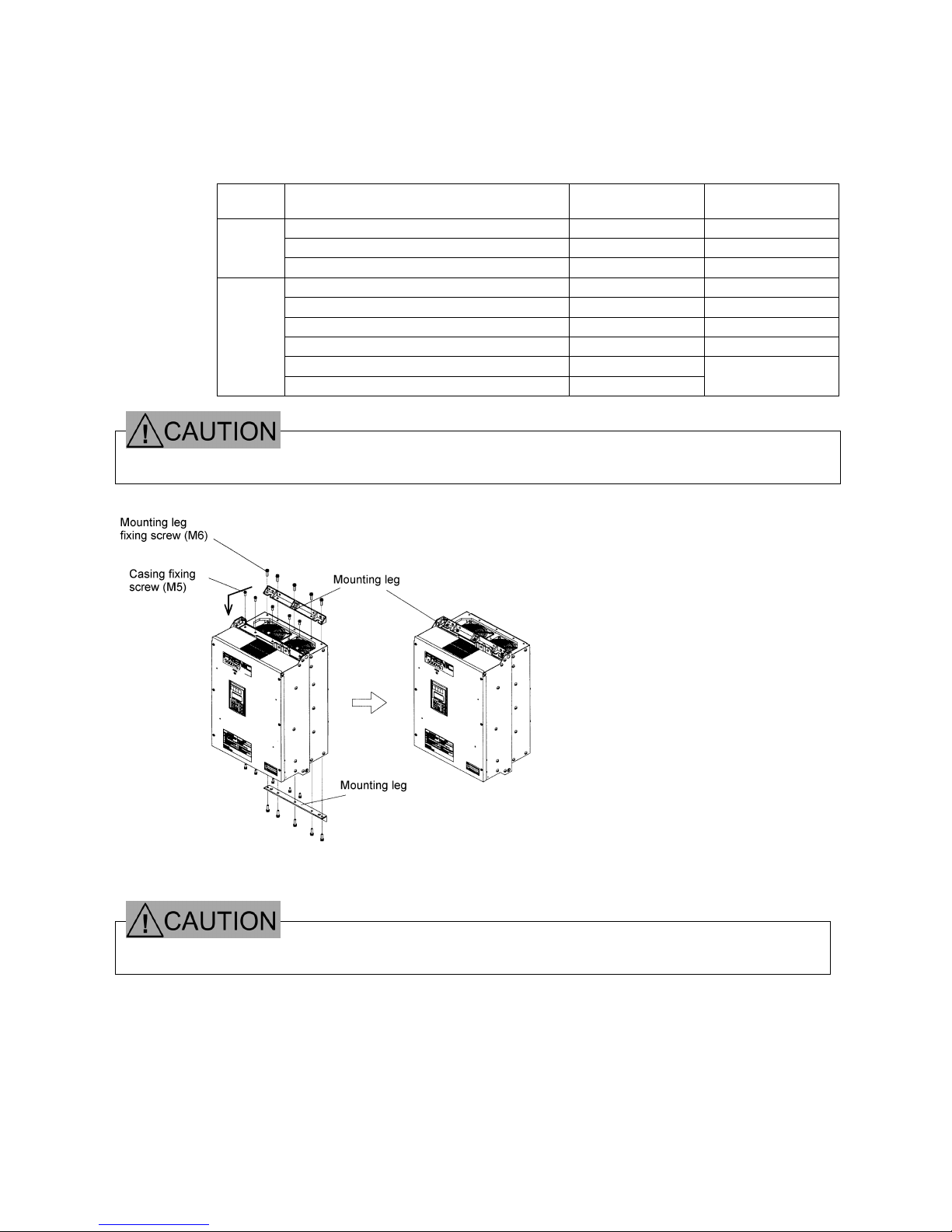
To externally cool a 18.5kW or higher inverter, relocate the upper and lower mounting legs as shown in Figure
2-2-3. Remove the mounting leg fixing screws, relocate the legs, and fix with casing fixing screws. (The
casing fixing screws cannot be directly used for some models. See the following table.)
The mounting leg fixing screws become unnecessary after the legs are relocated.
Number and Size of Fixing Screws
Voltage
class
Inverter model
Mounting leg fixing
screws
Casing fixing
screws
FRN18.5VG7S-2~FRN55VG7S-2
5 (M6 ´ 20) 5 (M5 ´ 16)
FRN75VG7S-2
7 (M6 ´ 20) 5 (M5 ´ 16)
200V
FRN90VG7S-2
6 (M6 ´ 20) 6 (M5 ´ 16)
FRN18.5VG7S-4~FRN75VG7S-4
5 (M6 ´ 20) 5 (M5 ´ 16)
FRN90VG7S-4~FRN110VG7S-4
7 (M6 ´ 20) 5 (M5 ´ 16)
Note 1
FRN132VG7S-4~FRN160VG7S-4
7 (M6 ´ 20) 7 (M5 ´ 16)
FRN200VG7S-4~FRN220VG7S-4
6 (M6 ´ 20) 6 (M5 ´ 16)
Note 1
FRN280VG7S-4~FRN315VG7S-4 Note 3
6 (M8 ´ 20)
400V
FRN355VG7S-4~FRN400VG7S-4
Note 3
8 (M8 ´ 20)
–
Note 2
· Do not use any screws other than specified.
Doing so may lead to fire or accident.
Figure 2-2-3
· Use the screws provided with the inverter when relocating the mounting legs.
Failure to do so may lead to injury.
Note 1: Fix the legs with M5 ´ 20 screws.
Note 2: Fix the legs with leg fixing
screws.
Note 3: The lower leg becomes
unnecessary when the inverter is
installed on its bottom.

2-4
2-3 Electric Connections
Removing the surface cover exposes the terminal blocks. Correctly wire them after reading the following
instructions.
2-3-1 Basic Connections
(1) Connect power supply leads to the main circuit power terminals, L1/R, L2/S, and L3/T. Connecting any
power supply lead to another terminal may fail the inverter. Check that the supply voltage does not exceed
the permissible limit indicated on the nameplate, etc.
(2) The grounding terminal must be grounded to prevent disasters such as electric shock and fire and reduce
the noise.
(3) Use a reliable crimp terminal to connect each lead.
(4) After making connections (wiring), check that:
1) leads are correctly connected,
2) all necessary connections are made, and
3) no terminal or wire is short-circuited or grounded.
(5) When any connection is changed after the inverter is energized:
It takes a long time for the smoothing capacitor in the DC link circuit of the main circuit to be discharged after
the power supply is shut off. After the CHARGE lamp goes off, check with a multimeter or such that the DC
voltage has been reduced to a safe level (25V DC or less). Short-circuiting a circuit in which a voltage
(potential) still remains may generate sparks. Wait until the voltage goes away.
· Always connect the grounding lead.
Failure to do so may lead to electric shock or fire.
· The wiring work should be performed by qualified persons.
· Before working, check that the power supply is shut off (open).
Failure to do so may lead to electric shock.
· Do not use any lead size other than specified.
Doing so may lead to fire.
2-5
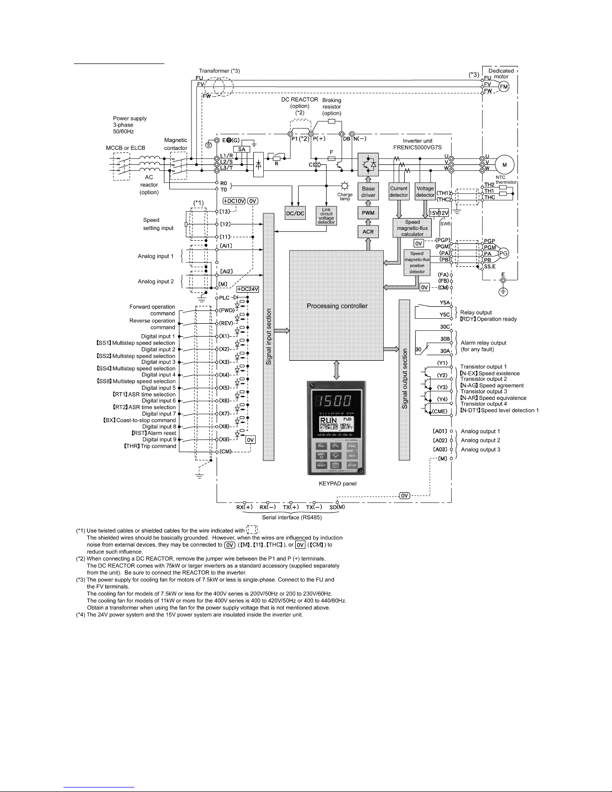
Basic Wiring Diagram
Figure 2-3-1 Basic Wiring Diagram

2-6
2-3-2 Wiring of Main Circuit and Grounding Terminals
Table 2-3-1 Functions of Main Circuit and Grounding Terminals
Terminal symbol Terminal name Description
L1/R, L2/S, L3/T Main circuit power input terminals Connected with three-phase power source.
U, V, W Inverter output terminals Connected with three-phase motor.
R0, T0 Auxiliary control power input terminals Connected with the same AC power source
as used for main circuit, as back-up power
source for control circuit.
P1, P(+) DC reactor connecting terminals Connected with (optional) input power-factor
correcting DC reactor.
P(+), DB Braking resistor connecting terminals Connected with (optional) braking resistor.
P(+), N(-)
DC link circuit terminals Supplies DC link circuit voltage.
Connected with (optional) external braking
unit or (optional) power regenerative unit.
zG
Inverter grounding terminals Grounds inverter chassis (casing).
Connected with earth.
(1) Main circuit power input terminals (L1/R, L2/S, and L3/T)
1) The main circuit power input terminals, L1/R, L2/S, and L3/T should be connected with the power source
via earth-leakage circuit breaker for line protection. Any phase may be connected to any lead. If the
zero-phase current is detectable by the upstream system, however, ordinary circuit breakers may be
used.
2) Connect a magnetic contactor so that the inverter can be disconnected from the power source to minimize
the influence of any failure when the inverter protective function is activated.
3) Do not start or stop the inverter by turning the main power switch on or off. Use the control circuit
terminals, FWD and REV, or the FWD, REV, and STOP keys on the KEYPAD panel to start or stop the
inverter. When the inverter is inevitably started or stopped using the main power switch, do not turn it on
or off more than once per hour.
4) Do not connect any terminal to a single-phase power source.
2-7
(2) Inverter output terminals (U, V, and W)
1) Connect three-phase motor leads to the inverter output terminals, U, V, and W with care not to connect a
wrong phase.
2) Do not connect a phase advancing capacitor or surge absorber (suppressor) to the inverter output
terminals.
3) If the wiring between the inverter and the motor is too long, a high-frequency current will run through the
wiring due to floating capacity to trip the inverter because of overcurrent, increase the leakage current,
and/or deteriorate the current indication accuracy. Therefore, the motor wiring length should not exceed
50m for 3.7kW or lower inverters or 100m for others, as a guide.
Connect the optional output circuit filter (OFL filter) if the wiring is too long.
4) When you use a motor with an encoder, limit the wiring distance between your inverter and motor to 100
m or less.
This limit is due to encoder characteristic. When the distance exceeds 100 m, you need an arrangement
such as inserting an isolation converter.
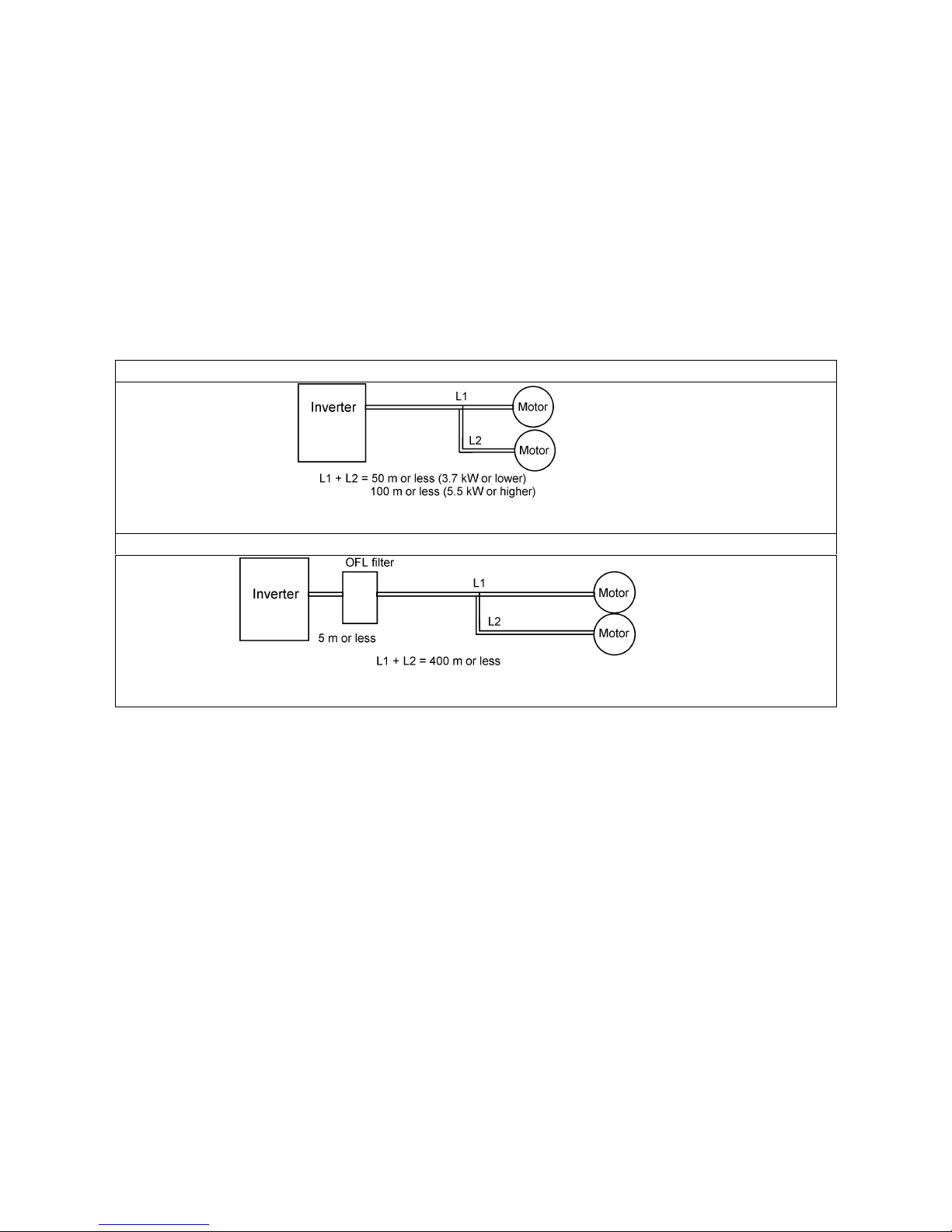
Without output circuit filter
When two or more motors are to be driven, the total length of wirings to those motors should not exceed 50m
for 3.7kW or lower inverters or 100m for 5.5kW or higher ones.
With output circuit filter
When two or more motors are to be driven, the total length of wirings to those motors should not exceed
400m.
Note: When a thermal relay is used between the inverter and the motor, especially for 400V series, the
thermal relay may malfunction even with a wiring length less than 50m. In this case, connect an
OFL filter or reduce the inverter operation noise (carrier frequency) using function code F26 (motor
sound (carrier frequency)).
· Driving a 400V motor with an inverter
If a motor is driven with a PWM inverter, the surge voltage generated by switching inverter elements is
overlapped as applied to the motor terminals. Especially for 400V motors, the motor insulation may be
deteriorated by the surge voltage if the motor wiring is too long. Therefore, any of the following measures
should be taken when a 400V motor is to be driven with an inverter.
1) Use a motor with reinforced insulation (all the Fuji Electric's general-purpose motors have reinforced
insulation).
2) Connect the optional output circuit filter (OFL filter) to the inverter output terminals.
3) Shorten the wiring between the inverter and the motor as short as possible (to10 to 20m or less).
2-8
Figure 2-3-4
(3) Auxiliary control power input terminals (R0 and T0)
If the magnetic contactor in the power supply circuit to
the inverter is turned off (open) when the protection
circuit is activated, the inverter control power supply is
shut off. As a result, alarm outputs (30A, B, and C)
are no longer retained and indications on the
KEYPAD panel go away. To prevent this, the same
AC voltage as used for the main circuit is applied to
the auxiliary control power input terminals, R0 and T0.
Although the inverter functions with no voltage
applied to these terminals, it is strongly recommended
to connect the voltage to R0 and T0 to ensure safe
operation.
1) When a radio noise filter is used, the power to be
connected to the auxiliary control power input
terminals, R0 and T0, should be taken from a point
downstream the filter.
If it is taken from a point upstream the filter, the
noise reduction effect is impaired.
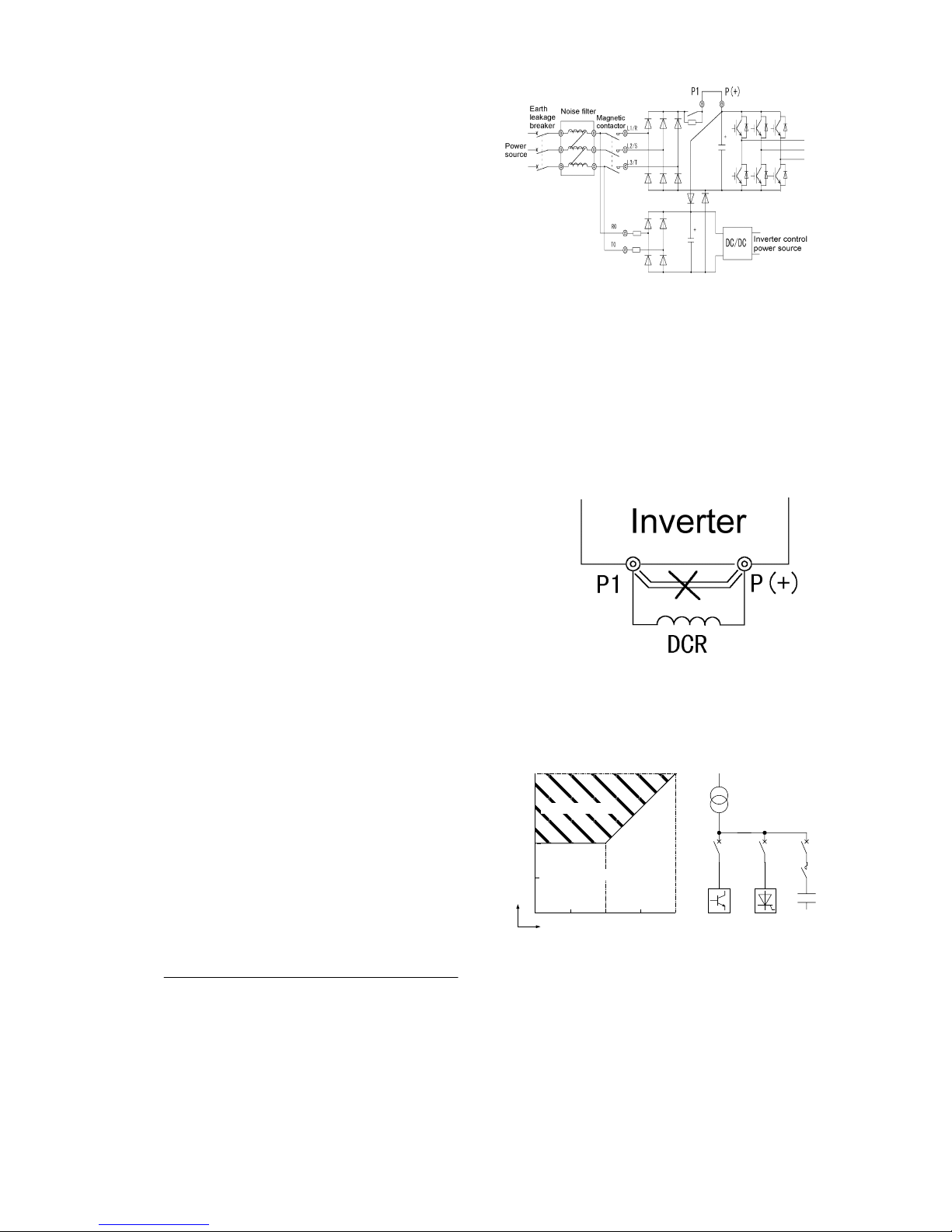
(4) DC reactor connecting terminals (P1 and P(+))
1) These terminals are provided to connect the
optional input power-factor correcting DC reactor.
A jumper is connected between the terminals
before delivery from the factory. Remove the
jumper before connecting the DC reactor.
2) Do not remove the jumper when the DC reactor is
not used.
Note: The DC reactors are (externally) provided as
standard equipment for 75kW or higher inverters.
Always use the DC reactor for those inverters.
3) Connect a DC reactor for an inverter meeting the
following conditions and having a rated motor
output of 55 kW or less.
・ The capacity ratio between the power transformer
and the inverter follows the Figure 2-3-4.
・ You connect a thyristor load to the same power
supply, or you control to turn ON/OFF a capacitor
adjusting power factor.
・ Imbalance of 2% or more exists in power supply.
Power supply voltage imbalance rate [% ]
Maximum voltage [V] – Minimum voltage [V]
Three-phase average voltage [V]
・ Improving input power factor is intended.
Power factor will be improved up to about 0.94.
Figure 2-3-3
Figure 2-3-2 Wiring of Auxiliary Control
Power Input Terminals
=
x 67
DC reactor required
(b)Power supply
system
Power supply
transformer
MCCB MCCB
MCCB
Inverter
Thyristor
converter
Power factor
adjusting
capacitor
(a)Capacity ratio
Power supply
transformer capacity
Inverter capacity [kVA]/unit
0100
500
1000
50
DC reactor not required
[kVA]
MC
2-9
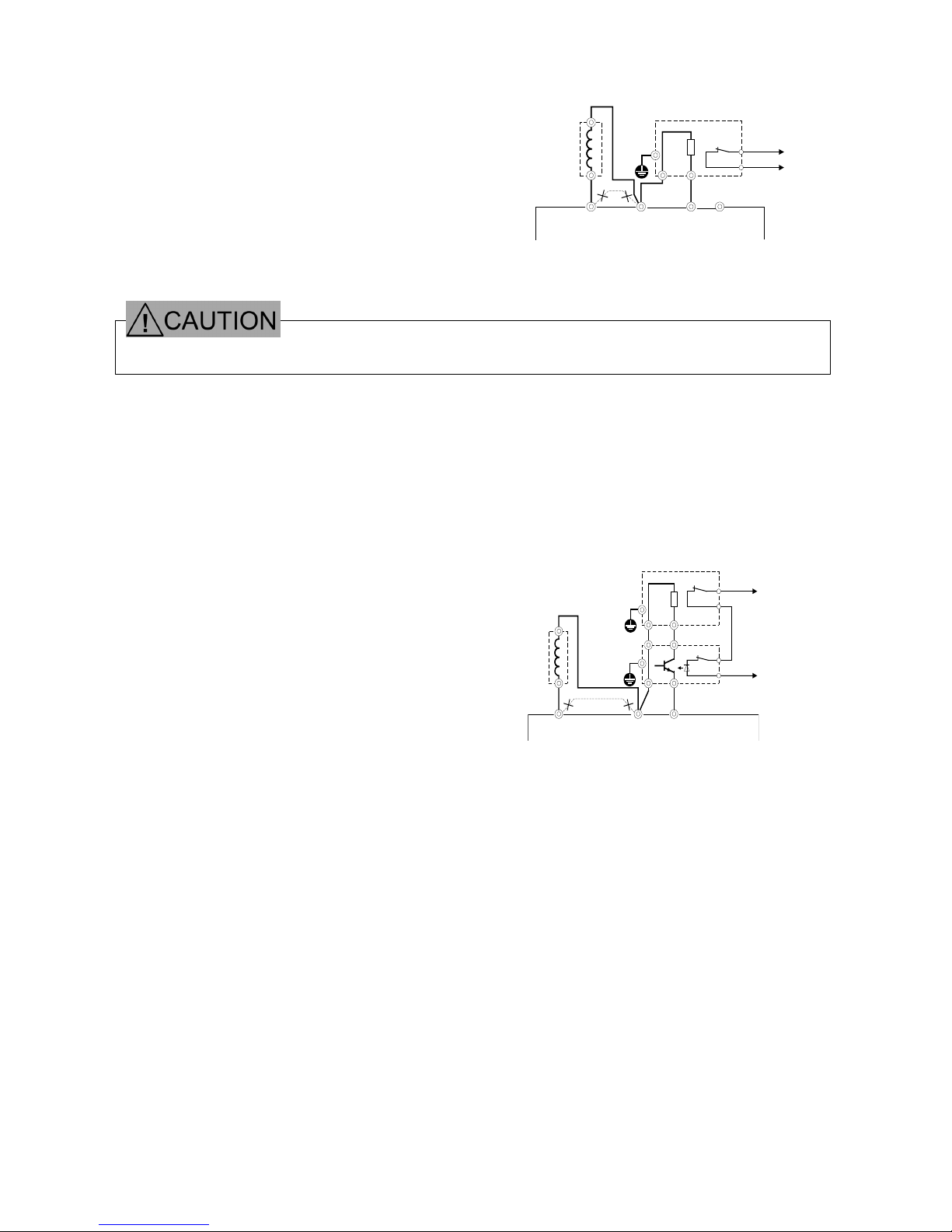
(5) Braking resistor connecting terminals (P(+) and DB)
The optional braking resistor may be externally
mounted. It is required when the inverter is
operated frequently or under heavy inertia.
1) Connect the braking resistor terminals, P(+) and
DB, to the inverter terminals, P(+) and DB.
2) Lay out so that the wiring length will not exceed
5m. The two leads should be twisted or in close
contact (parallel).
· Do not directly connect the braking resistor to the DC terminals, P(+) and N(-).
Doing so may lead to fire.
(6) DC link circuit terminals (P(+) and N(-))
The 200V series, 75kW or higher and 400V
series, 132kW or higher inverters contain no
braking resistor drive circuit. When the braking
resistor is required, a braking unit should be
used.
1) Connect the braking unit terminals, P(+) and
N(-), to the inverter terminals, P(+) and N(-).
Lay out so that the wiring length will not
exceed 5m. The two leads should be twisted
or in close contact (parallel).
2) Connect the braking resistor terminals, P(+)
and DB, to the braking unit terminals, P(+) and
DB. Lay out so that the wiring length will not
exceed 10m.
The two leads should be twisted or in close
contact (parallel).
When the inverter terminals, P(+) and N(-),
are not used, they should be left open. Never
short these terminals or directly connect the
braking resistor. Doing so may break the
inverter.
3) Auxiliary contacts 1 and 2 of the braking unit
have polarity. When connecting a PWM
Converter, see the instruction manual for the
unit.
P1 P(+)DBN(
-
)
DC reactor
(DCR)
Braking resistor DB
G
PDB
2
1
(CM)
(THR)
ZZ
Figure 2-3-5 Connection Diagram
(For 200V, 55kW or Lower and 400V, 110kW or
Lower Inverters
)
DC reactor
(DCR)
P1 P(+) N(-)
External braking resistor DB
G
P
DB
G
P(+)R
P(+)
N(-)
Braking unit BU
1
2
1
2
DB
(CM)
(THR)
Figure 2-3-6 Connection Diagram
(200V, 75kW or Higher and 400V, 132kW
or Higher Inverters)
*More than one braking units or braking
resistors may be needed according to a
model. For the details of connection,
refer to the instruction manual for the
braking unit.

2-10
(7) Inverter grounding terminals (
zG)
The inverter grounding terminals,
zG, must be grounded to ensure your safety and for noise measures.
The Technical Standards for Electric Equipment requires metallic frames of electric equipment be grounded
to prevent disasters such as electric shock and fire. Connect the terminals as described below.
1) Connect to type D grounded poles for 200V series or type C grounded poles for 400V series according to
the Technical Standards for Electric Equipment.
2) Connect the earth terminal to the dedicated grounding pole of the inverter system using a thick, short lead.
Table 2-3-2
Voltage class Grounding work class Grounding resistance
200V Type D
100W or less
400V Type C
10W or less
(8) Auxiliary power switching connector (CN UX) (18.5kW or higher)
For 18.5kW or higher inverters, if the supply voltage to the main circuit is within the range shown in
Table 2-3-3, reconnect the auxiliary power switching connector, CN UX, to U2
. For other inverters, leave
the connector connected to U1
. For details, see Figure 2-3-9.
Table 2-3-3 Voltage Ranges Requiring Reconnection of Auxiliary Power Switching Connector
Frequency [Hz] Supply voltage range [ V ]
50 380 to 398
60 380 to 430
· Check that the number of phases and rated voltage of the product agree with those of the
AC power source.
· Do not connect any AC power source to the output terminals, U, V, and W.
Doing so may lead to injury.
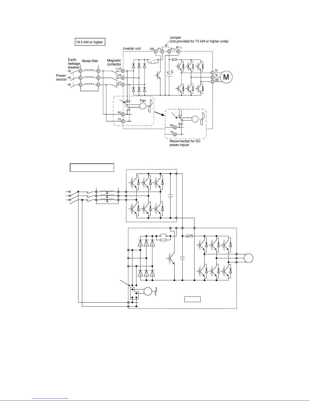
(9) Fan power switching connector (CN RXTX) (18.5kW or higher)
The VG7S accepts DC power inputs through a common DC terminal without using any optional equipment
when combined with a PWM converter as shown in Figure 2-3-8.
However, 18.5kW or higher inverters contain AC power operated parts such as AC cooling fan. When such
DC power inputs are used, reconnect the fan power switching connector, CN RXTX, inside the inverter to
R0-T0
as shown in Figure 2-3-6 and apply an AC power to the terminals, R0 and T0.
For details, see Figure 2-3-9.
Note: The fan power switching connector, CN RXTX, is normally connected to L1/R-L3/T. Do not reconnect the
connector when no DC power inputs are used.
Always connect the same AC voltage as used for the main circuit to the auxiliary control power input
terminals, R0 and T0. Failure to do so deactivates the fan, which may overheat (OH1) and then fail the
inverter.
· Do not connect the fan power switching connector, CN RXTX, inside the inverter to a wrong terminal.
Doing so may fail the inverter.
· When DC power inputs are used, apply an AC power to R0 and T0 to drive the fan.
Failure to do so may fail the inverter.
2-11
Figure 2-3-8 An Example of Wiring of Inverter Combined with PWM Converter
Note 1: When a 15kW or lower inverter is combined with a PWM converter, do not directly connect any power
source to the auxiliary control power input terminals, R0 and T0. If connected to these terminals, the
power source should be insulated from the main power supply to the PWM converter with insulating
transformer.
Examples of wiring of the PWM converter are given in the instruction manual for PWM converter.
Note 2: 200V, 75kW or higher and 400V, 132kW or higher inverters contain no braking transistor.
L1/R
L2/S
L3/T
DB P1 P(+) N(-)
+C
M
U
V
W
Fan
CN RXTX
R0
T0
18.5kW or higher
Inverter unit
L1/R
Filter
Earth
leakage
breaker
Power
source
Magnetic
contactor
L2/S
L3/T
C+
P(+)
N(-)
PWM converter (RHC series)
Reconnect CN RXTX
to .
R0-T0
CN RXTX
CN RXTX
Figure 2-3-7 Reconnection of Fan Power Switching Connector
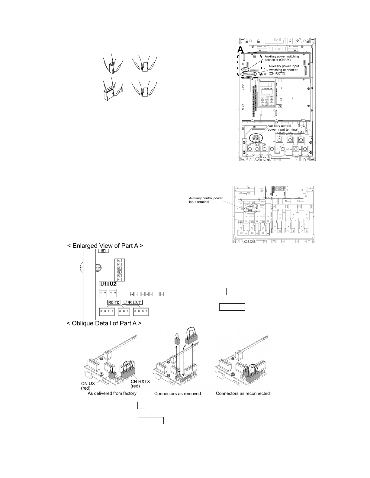
2-12
The switching connectors are mounted in the power PC board at the
top of the control circuit PC board.
Note: When removing either connector, hold the top of the jaw
between fingers to release the latch and remove by pulling
upward.
When mounting, fully insert the connector and apply the latch
until it clicks.
Figure 2-3-9 Power Switching Connectors (18.5kW or Higher Inverters Only)
CN UX
CN RXTX
CN UX
: U1
CN RXTX : L1/R-L3/T
FRN18.5VG7S-2 to FRN55VG7S-2
FRN18.5VG7S-4 to FRN110VG7S-4
FRN75VG7S-2 to FRN90VG7S-2
FRN132VG7S-4 to FRN220VG7S-4
The Figure applies when the inverter is
used with DC power inputs at a supply
voltage of 380-398V, 50Hz or 380-430V,
60Hz.
CN UX is connected to U1
and CN RXTX to L1/R-L3/T before factory shipment.
 Loading...