

Page 1
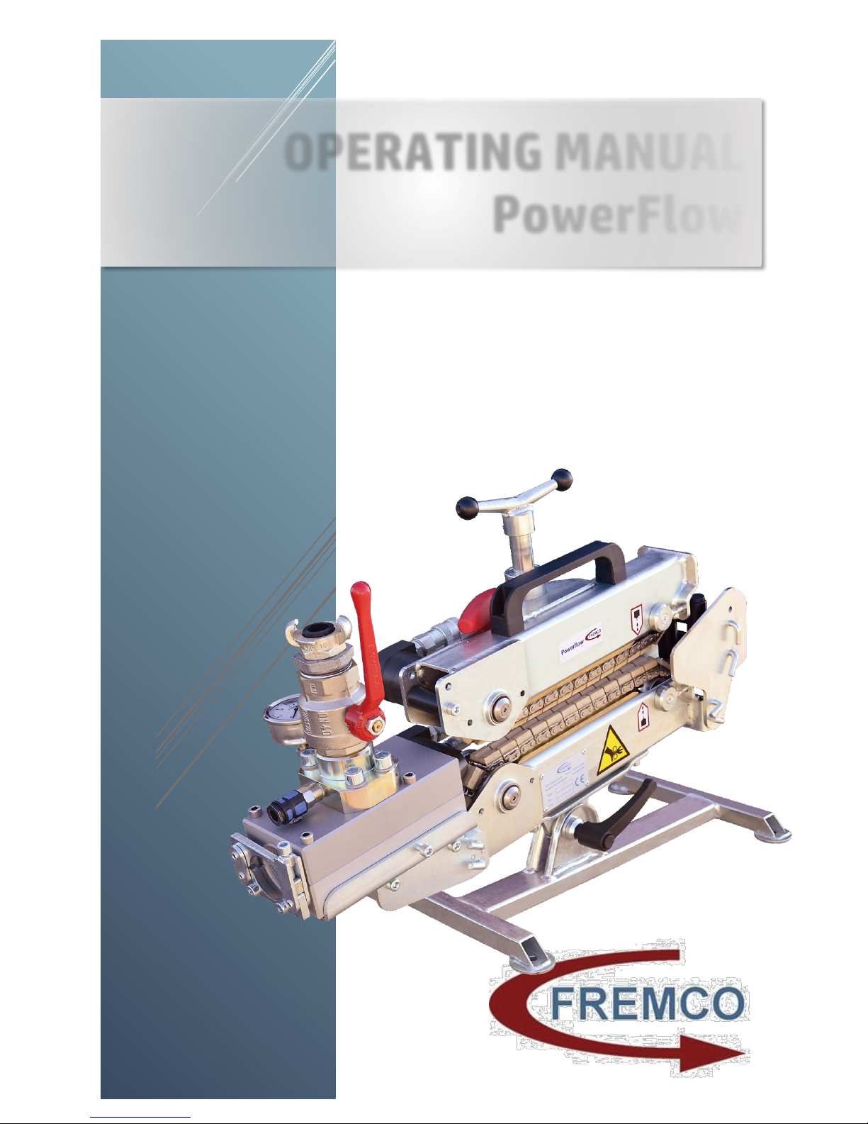
OPERATING MANUAL
PowerFlow
Fremco A/S
Ellehammervej 14
9900 Frederikshavn
Denmark
Tel. +45 72 30 12 13
101-10001 Operating Manual
2013-01-03 EN
Page 2
101-10001 OPERATING MANUAL ©2013-01-03 EN
The material is copyright protected
2
Table of Content
Technical Specifications ....................................................................................................................................... 3
PowerFlow Blowing Machine ................................................................................................................ 3
Hydraulic Control Unit ............................................................................................................................ 4
Big Flow Blowing Junction Block ........................................................................................................... 5
Identification .......................................................................................................................................................... 6
Application ............................................................................................................................................................. 6
Mounting ................................................................................................................................................................ 6
Supply of Air or Water Pressure .......................................................................................................................... 7
Blowing a Fiber Cable into a Duct ....................................................................................................................... 7
Preparing for Blowing ............................................................................................................................ 7
Use of Compressed Air for Blowing ...................................................................................................... 8
Use of Water for Blowing ....................................................................................................................... 8
Maintenance .......................................................................................................................................................... 9
Safety Directions ................................................................................................................................................. 10
Format and Wear Parts ...................................................................................................................................... 10
Recommended Accessories .............................................................................................................................. 10
EC Declaration of Conformity ............................................................................................................................ 11
Page 3
101-10001 OPERATING MANUAL ©2013-01-03 EN
The material is copyright protected
3
Technical Specifications
These specifications cover PowerFlow as well as the hydraulic control unit and the blowing
junction block for microducts. The blowing junction block is a replaceable format part that
must fit the actual size of the fiber cables/microducts and ducts in question.
PowerFlow
Manufacturer Fremco A/S
Ellehammervej 14
9900 Frederikshavn
Denmark
Item No. ................................................................................................................................................ 101-10001
Cable/microduct diameter ..................................................................................................................... 8-25 mm
Duct diameter ........................................................................................................................................ 18-70 mm
Blowing distance¹ ............................................................................................................................. Up to 10 km
Blowing speed¹ .......................................................................................................................... Up to 80 m/min.
Recommended water pressure ........................................................................................................... 10-20 bar
Recommended pressure and airflow²: ................................................... 8-12 bar (8,000-12,000 l/pr. min.)
Weight ............................................................................................................................................................. 38 kg
Length ........................................................................................................................................................ 650 mm
Width .......................................................................................................................................................... 230 mm
Height ......................................................................................................................................................... 350 mm
¹ Depending on type and quality of fiber cable and microduct
² Cooled and dried air
Page 4
101-10001 OPERATING MANUAL ©2013-01-03 EN
The material is copyright protected
4
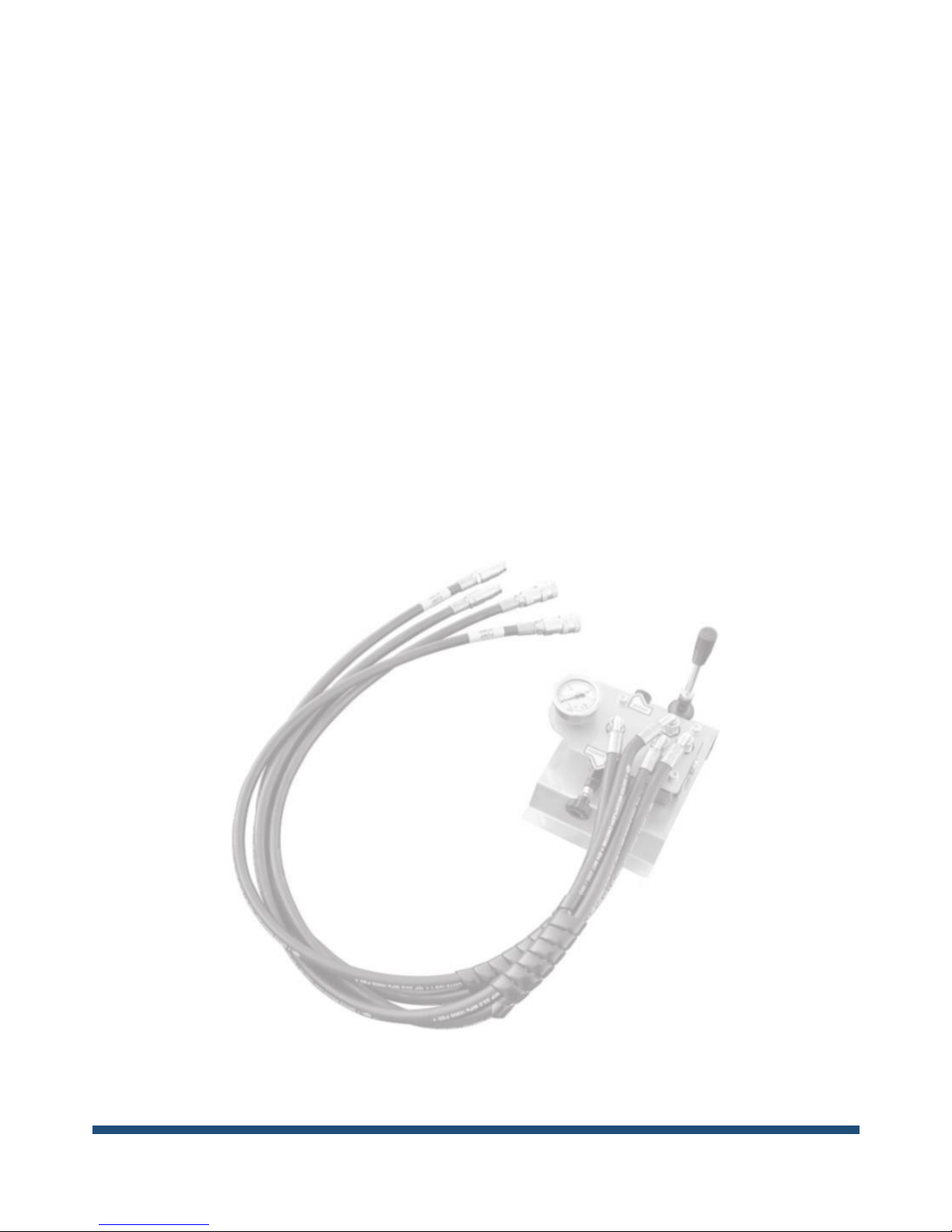
Hydraulic Control Unit
Manufacturer Fremco A/S
Ellehammervej 14
9900 Frederikshavn
Denmark
Item No. .............................................................................................................................................. 103-10041
Hydraulic connection ......................................................................................................... 0>125 bar, 17 l/min
Manometer ................................................................................................................................................. 160 bar
Hose to fiber blowing machine ........................................................................................................... 1500 mm
Hose to hydraulic pump ........................................................................................................................ 1500 mm
Length ........................................................................................................................................................ 250 mm
Width .......................................................................................................................................................... 250 mm
Height ......................................................................................................................................................... 310 mm
Weight ............................................................................................................................................................... 5 kg
Page 5
101-10001 OPERATING MANUAL ©2013-01-03 EN
The material is copyright protected
5
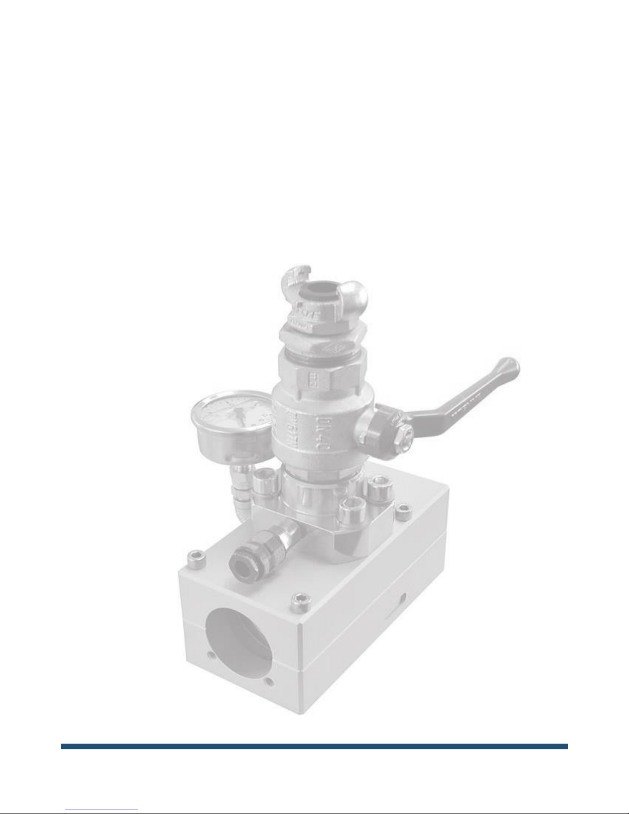
Big Flow Blowing Junction Block
For blowing multiple microducts or single cable
Manufacturer Fremco A/S
Ellehammervej 14
9900 Frederikshavn
Denmark
Item No. ...................................................................................................................................... 103-130424001
Length ........................................................................................................................................................ 270 mm
Width .......................................................................................................................................................... 100 mm
Height without connection pipe .............................................................................................................. 230 mm
Weight ............................................................................................................................................................... 5 kg
Page 6

101-10001 OPERATING MANUAL ©2013-01-03 EN
The material is copyright protected
6
Identification
These instructions have been made to support
the users of the cable blowing machine
PowerFlow. The machine type can be identified
by the type plate on the machine. The type
plate provides information about serial
number, year of production and name and
address of the manufacturer.
It is recommended to read this instruction
carefully and become familiar with the
functionality and maintenance of the cable
blowing machine before use.
Application
The cable blowing machine PowerFlow is
constructed for blowing fiber optic cables into
ducts. An example might be a 12 mm cable
into a 40 mm duct.
Always use format parts designed for the
actual diameter of cable and duct.
It is very important to use the correct format
parts. If the format parts do not fit the duct,
dangerous situations may occur.
Mounting
Depending on the facilities, mount the air
compressor or water pump and the hydraulic
MultiPower Pack in inserting direction in front
of the manhole. Check oil and fuel, and testrun equipment.
Arrange the PowerFlow in front of the manhole
and guide the duct out of the hole and into the
Powerflow. If the duct cannot reach the
PowerFlow, extend the length with an extra
piece of duct and a connector. Connect the
hydraulic MultiPower Pack to the hydraulic
control unit.
Make sure to place the Powerflow machine on
a stable foundation and to fasten it to
withstand the forces, which occur during use.
These push/pull forces can be up to 125 kg.
Be careful to avoid any dirt on the surfaces
when mounting the duct into the blowing
junction block. Tighten the four screws equally
so that the two halves are pressed completely
together.
The cable seals in the black nylon part of the
blowing junction block must fit tightly around
the cable – the hole in the cable seal should be
no more than 0.5 mm larger than the diameter
of the cable. Use one to three cable seals
depending on the expected pressure. New
cable seals should always be installed after
each cable blowing to secure maximum
sealing.
The hydraulic control unit controls the direction
(forward/back), speed and push/pull force.
Use the joystick on the hydraulic control unit to
control start/stop and direction.
Speed can be adjusted by turning the screw
marked “Speed”. By turning the screw to the
left, pressure is reduced.
With the screw marked “Force” you can adjust
the maximum force to be transferred to the
cable. The pressure, and with it the force, is
increased when the screw is turned to the right.
Use the manometer to read the pressure and
thereby the push/pull force.
CAUTION: Do not use excessive
force, as this can damage the fiber
cable.
Page 7

101-10001 OPERATING MANUAL ©2013-01-03 EN
The material is copyright protected
7
Supply of Air or Water Pressure
It is possible to use compressed air as well as
water for blowing cables. Air is best suited
for shorter distances (0-500 m) and for jobs
where water in the ducts should be avoided. It
is very important that the quality and volume
of compressed is correct and meets the
specifications.
If there is water in the air or too low pressure
and volume, it will create insufficient results.
The minimum compressor capacity is 8000
l/min. The compressed air must be filtered,
cooled and dried to avoid moisture and dirt in
the microduct.
Blowing a Fiber Cable into a Duct
Before preparing to blow, make sure that all format parts fit the number and diameter of the
microducts/cable and duct.
Preparing for Blowing
Arrange the cable drum equipment approx. 10 m in front of the Powerflow. Check that the drum
can turn easily and that the setup is stable.
Start the hydraulic MultiPower Pack for cable blowing machines. Adjust to 50-75% power and
let it run 2-5 minutes.
Connect the hoses from the hydraulic control unit to the hydraulic pump.
Adjust the hydraulic control unit to 60-70 bar
Turn off the hydraulic pump.
Connect the hoses from the hydraulic control unit to the Powerflow.
Put the fiber cable through the guide, the chains and the blowing junction block.
Adjust the blowing junction block vertically to align it with the fiber cable coming through the
chains.
REMEMBER to tighten the chains around the fiber cable using the handle on top of the machine.
Attach a cable tip on the fiber cable
Page 8

101-10001 OPERATING MANUAL ©2013-01-03 EN
The material is copyright protected
8
Use of Compressed Air for Blowing
Add approximately 100-500 ml lubricant to the duct, and then place a foam plug in the
duct as well.
Connect the duct to the blowing junction block.
Connect compressed air to the blowing junction block.
Turn on air to the blowing junction block – only for a short time – until the foam plug comes out
at the other end of the duct.
Turn on the hydraulic MultiPower Pack and start the Powerflow machine by moving the joystick
on the hydraulic control unit
Increase air to the blowing junction block gradually.
CAUTION: Check continuously that the drum turns smoothly. If not, check the pressure of the top
chain on the fiber cable. Intensify if necessary.
Use of Water for Blowing
Connect the duct to the blowing junction block.
Connect the suction tube from the water pump to the water supply.
Start the engine on the water pump and let it run for approximately 4-5 min.
Connect the pressure tube from the water pump to the blowing junction block.
Turn on the hydraulic MultiPower Pack and start the machine by moving the joystick on the
hydraulic control unit.
Increase water to the blowing junction block gradually.
CAUTION: Check continuously that the drum turns at steady speed. If not, check if the water
pressure and flow is sufficient or/and intensify the pressure of the top chain on the fiber cable.
Page 9
101-10001 OPERATING MANUAL ©2013-01-03 EN
The material is copyright protected
9
Maintenance
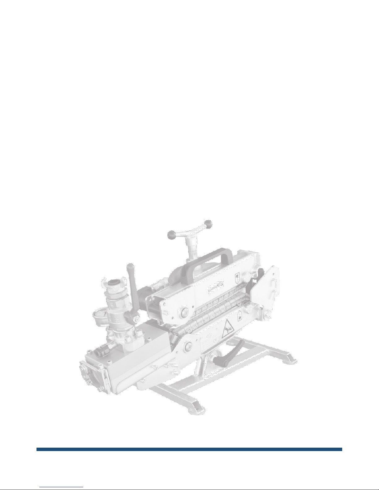
The PowerFlow cable blowing machine does
not require much maintenance, if a simple set
of rules is followed.
See to it that the guide rollers, where the fiber
cable enters the chains, are adjusted in a way
that the cable is guided directly into the middle
of the drive chains.
The chains should be kept well lubricated and
free from sand and dirt. Use a good quality
chain oil, preferably from a spray.
The chain pressure mechanism should be
lubricated regularly with an ordinary grease
lubricant.
The chains should be tightened to an extent
that the they can be lifted only 5-10 mm from
the support rail.
The chain support rails must be replaced when
the side plates on the chain touch the support
rails.
It is very important to avoid any kind of dirt in
the hydraulic connectors, when mounting the
hydraulic hoses.
If the machine is not to be used for a longer
period of time, it should be cleaned, and the
chains should be lubricated. It is also
recommended to spray the machine with an
anticorrosion oil. Store the machine in a dry
and dust-free environment.
It is strongly recommended to use original
spare parts. Repairs should be performed by
the manufacturer. Errors and damage due to
unauthorized use, changes or adjustment of
the machine are not covered by warranty.
Page 10
101-10001 OPERATING MANUAL ©2013-01-03 EN
The material is copyright protected
10
Safety Directions
Make sure to disconnect the machine from
all power sources, like air compressor and
hydraulic pump, before any kind of
adjustment and maintenance takes place.
The hydraulic power supply from the pump
for cable blowing machines or from other
sources may never exceed the specified
maximum pressure.
The air or water pressure should never
exceed the recommendations from the
suppliers of microducts, fiber cables and
duct. The pressure may never exceed 20
bar, which is the maximum pressure for the
blowing junction block.
Observe that the machine is placed on a
stable foundation and secure it before start.
Make sure the blowing junction block is
properly connected to the duct and that the
microducts/cable are placed correctly
between the chains.
Make sure you do not touch the
microducts/cable too close to the machine
because you risk getting your fingers
injured, and make sure the microducts or
the cable do not make loops that might be
dangerous to people around the machine.
Use hearing protection, if the hydraulic
pump or other noisy equipment is placed
nearby.
The joystick on the hydraulic control unit
should never be blocked in a way, where it
is unable to return to neutral position.
The operator must make sure that no other
persons are close to the machine and cable
drums in a way that could be dangerous
when the machine is started.
It is always a clear advantage to be well
prepared so that you can run the blowing
process without interruptions. Stopping in
the middle of the process creates a risk of
being unable to start again.
Make sure the working environment is clean
and tidy to avoid injuries due to stumbling
over cables and equipment.
Format and Wear Parts
Please ask your authorized dealer for a
complete list.
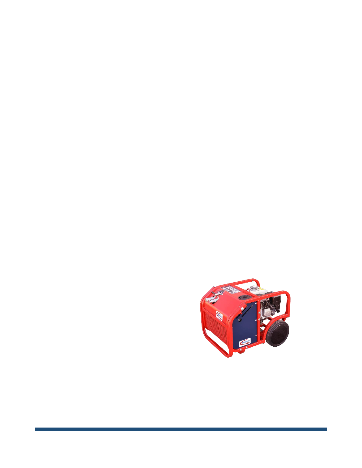
Recommended Accessories
Using other hydraulic power sources can
potentially cause damage on the Powerflow
blowing machine. It is highly recommended to
use the hydraulic power unit from Fremco:
101-10102 hydraulic MultiPower Pack
Page 11

101-10001 OPERATING MANUAL ©2013-01-03 EN
The material is copyright protected
11
EC Declaration of Conformity
We hereby declare that
101-10001 Powerflow Blowing Machine for cables
is manufactured in conformity with the EC Directives 2006/42/EC
Fremco A/S
Ellehammervej 14
DK-9900 Frederikshavn
Denmark
Niels Søgaard Hansen
General Manager
01.04.2012
Fremco A/S ● Ellehammervej 14 ● 9900 Frederikshavn ● Denmark ●Tel. +45 72 30 12 13
 Loading...