


Dual in-line Package Raspberry Pi PICO
For Battery, USB and Extended Powered IoT WiFi
Applications
with Embedded UPS Functionality
DiP-Pi PIoT
Supported Models PIoT: Full, Power Master and WiFi Master
No Solder – No cables – No Lost Time
User Guide
Especially designed for the Raspberry Pi® PICO
“Raspberry Pi” is a trademark of the Raspberry Pi® Foundation.
Designed and Manufactured by www.pimodules.com

Table of Contents
SYSTEM OVERVIEW 3
INTRODUCTION 3
AVAILABLE DIP-PI PIOT MODELS 3
DIP-PI PICO PIOT FULL 4
DIP-PI PICO POWER MASTER 4
DIP-PI PICO WIFI MASTER 4
DIP-PI PIOT TECHNICAL SPECIFICATIONS 4
SETTING UP PROCEDURE 8
INSTALLING THONNY AND TESTING YOUR RASPBERRY PI PICO 8
Simple Blinking Raspberry Pi© Pico LED Micro-Python Program 10
HARDWARE INSTALLING ON RASPBERRY PI PICO 11
HARDWARE INTERFACING/INTERACTION WITH RASPBERRY PI® PICO 13
BATTERY CONNECTION 14
EXTENDED POWERING CABLE CONNECTION 14
ON/OFF SLIDE SWITCH AND RESET SWITCH 14
UPS FUNCTIONALITY 15
EMBEDDED LI-ION LIPO CHARGER 15
ESP8266 WIFI EMBEDDED MODULE 15
WT8266 WIFI EMBEDDED MODULE AT COMMANDS SET 16
WIFI FIRMWARE UPLOADER SWITCH 16
MICRO SD CARD SOCKET 17
INFORMATIVE LEDS 17
DIP-PI PIOT INTERFACES 17
A/D INTERFACES 18
1-WIRE INTERFACE 18
DHT11/22 INTERFACE 19
READY-TO-USE EXAMPLES 20
COMMON PROBLEMS & SOLUTIONS 20
CAN I CONNECT EPR (6-18VDC) INPUT AND RASPBERRY PI PICO MICRO-USB AT THE SAME TIME? 20
WHEN I SWITCH OFF WITH THE SLIDE SWITCH AND MICRO-USB IS CONNECTED, THE VUSB AND IS STILL LIGHT. 20
DOCUMENT REVISIONS 20
DIP-PI PIOT SCHEMATIC 20
Designed and Manufactured by www.pimodules.com

System Overview
Introduction
Dual in-Line Package Raspberry Pi PICO (DiP-Pi PICO) is a family of self-containing, stackable add-ons
to the Raspberry Pi PICO® that decrease to the minimum user involvement for hardware
development of application/idea testing based on Raspberry Pi PICO. DiP-Pi PICO takes care to
support with all basic functionalities possible required by under development user application. User
can easy stack-up (if used Stack headers) 2, 3 or more separated DiP-Pi PICO, possible add own PCB
and rapidly run their application or use as a standalone self-containing device together with
Raspberry Pi PICO® (if used Top-End headers). If designed application fulfills required needs; after
successfully testing, user has 3 solutions:
● It is possible to use selected and tested DiP-Pi set and use them as it is for the application,
● User design the hardware by himself based on selected and tested DiP-Pi,
● And finally, ask Designer and Manufacturer company (www.pimodules.com) to design a
single PCB (and if needed manufacture) based on tested DiP-Pi set. Pi Modules has signed
agreement with Raspberry Pi and currently is “Raspberry Pi Approved Design Partner”
The list of available DiP-Pi is long and continuously updated with new DiP-Pi. Each DiP-Pi is
supported with a simple code supporting its features (written in micro-Python or C).
The DiP-Pi PICO PIoT (named also DiP-Pi PIoT) is an advanced powering system, with UPS
functionality, that cover all possible powering needs for application build-up based on Raspberry Pi
PICO. It is supplying the system with up to 1.5A@5V from 6-18 VDC on various powering sources like
Cars, Solar Panels industrial plant etc. It supports LiPo or Li-Ion Battery charger as also simply
switching from cable powering to battery powering or reverse (UPS functionality). The EPR power
source is protected with PPTC Resettable fuse, Reverse Polarity, as also ESD. The DiP-Pi PIoT contains
Raspberry Pi PICO embedded RESET button and ON/OFF switch on all powering sources (USB, EPR or
Battery). User can monitor (via A/D) battery level and External Powering Level with PICO’s A/D
converters. Both A/Ds are protected also from ESD spikes with additional protection TVS. If for any
reason user needs to use those PICO pins for their own application a simple 0402 resistors (0 OHM)
need to be easy removed.
The charger is automatically charging connected battery (if used) but in addition user can switch it
ON/OFF if their application needs it.
Each powering source or battery charger status is indicated by separate informative LEDs (VBUS, VSYS,
VEPR, 3V3, CHGR).
User can use any capacity of LiPo or Li-Ion type, however, must take care to use PCB protected
batteries. The charger is set to charge battery with 240 mA current. This current is set by resistor so if
user need can himself change it to higher or lower value adjusting current to application exact needs.
It can be done also by Manufacturer on customer request.
Designed and Manufactured by www.pimodules.com

Available DiP-Pi PIoT Models
The DiP-Pi PICO PIoT is assembled around of a single PCB and is offering 3 different devices. There
are:
DiP-Pi PICO PIoT Full
This model is equipped with all available features, including extended powering, Battery Charger, UPS
Functionality, micro–SD Card, WiFi Module, Interfaces and ON/OFF features.
A detailed list of features is provided below on Table 1 DiP-Pi PIoT Technical Specifications
DiP-Pi PICO Power Master
This model is equipped with reduced set of features, and including extended powering, Battery
Charger, UPS Functionality, Interfaces and ON/OFF features.
A detailed list of features is provided below on Table 2 DiP-Pi PIoT Technical Specifications
DiP-Pi PICO WiFi Master
This model is equipped with reduced set of features including micro–SD Card, WiFi Module,
Interfaces and ON/OFF features.
A detailed list of features is provided below on Table 3 DiP-Pi PIoT Technical Specifications
DiP-Pi PIoT Technical Specifications
Mechanical
PIoT
WiFi
Master
Power
Master
DiP-Pi PCB dimensions
21mm x 51mm
YES
YES
YES
Raspberry Pi PICO Footprint
compliance
Yes, size and pinout
YES
YES
YES
Raspberry Pi PICO headers
Male, female, or female-male
(pass thru)
YES
YES
YES
External Cable Powering
EPR Power Input
6-18V DC
YESNOYES
Current/Voltage Supply
1.5A@4.8V
YESNOYES
EPR Power Input Protections
Reverse Polarity, PPTC FUSE,
ESD
YESNOYES
Recommended EPR Power Input
Plug
Plug; DC supply; female;
3.4/1.4mm
YESNOYES
EPR Power Input Socket
Socket, DC Supply, male,
Contact size 3.4/1.3mm or
3.5/1.3mm
YESNOYES
EPR Level monitoring
Yes, via ADC1 (GP27), pass thru
0R 0402 resistor, easy to be
YESNOYES
Designed and Manufactured by www.pimodules.com

removed if this specific GP is
needed for other application
External Powering and USB
Powering ON/OFF
Supported by ON/OFF Slide
Switch
YES
YES
YES
Raspberry Pi PICO USB Powering
Compliant
YES
YES
YES
Raspberry Pi PICO Power Entry
Point
VSYS Pin
YESNOYES
Battery Powering
Supported Battery Types
PCM Protected (2A Max
allowed Current – 2A) LiPo and
Li-Ion Batteries
YESNOYES
Battery Socket
Male JST 2.5mm
YESNOYES
Battery Charger Current
240 mA
YESNOYES
Battery Fuel Gauge
Software - provided by
Manufacturer
YESNOYES
(optional) Charger ON/OFF.
Normally charger is working
automatically, and not need any
user intervention
Yes, via GP21, pass thru 0R
0402 resistor, easy to be
removed if this specific GP is
needed for other application
YESNOYES
BAT Level monitoring
Yes, via ADC1 (GP26), pass thru
0R 0402 resistor, easy to be
removed if this specific GP is
needed for other application
YESNOYES
ON/OFF Functionality
Supported by ON/OFF Slide
Switch on All Power Sources
YESNOYES
UPS Functionality
Yes, automatic if Cable power
missing (EPR, USB) both
directions (from missing cable
to battery powering and vice
versa)
YESNOYES
Indicators - Switches
Informative LEDs
VB (VUSB), VS (VSYS), VE
(VEPR), CH(VCHR), V3(V3.3)
YES
YES
YES
Switches
PICO Reset, ON/OFF on all
Powering Sources (EPR, USB
and BAT), WiFi LD-NO (Normal
usage, Loading ESP new
firmware – usually not needed)
YES
YES
YES
WiFi
WiFi Module
Based on clone ESP8266 Clone
– WT8266
YES
YES
NO
Connectivity with Raspberry Pi
PICO
UART0RX(GP13),
UART0TX(GP12), WiFi Reset
(GP15), WiFi ENABLE(GP11)
used when ultra-low power is
needed. Examples provided
contains simple WEB server set
up. Interaction with WiFi is
done via AT commands.
YES
YESNOMicro SD Card Socket
Designed and Manufactured by www.pimodules.com

Interface Type
Standard micro–SD Cards
Interface recommended by
Raspberry Pi (single bit
interface - SPI). Raspberry Pi
PICO can store/read data or
run software from the SD card.
YES
YES
NO
Connectivity with Raspberry Pi
PICO
SPI0
SD_MISO(GP16), SD_CS(GP17),
SD_CLK(GP18),
SD_MOSI(GP19),
SD_DET(GP20), – if SD card is
not used the GPXX can be used
in other applications
YES
YESNOEmbedded ESD protected 1-wire interface
Type 1-Wire Interface
Direct independent Interface
(separated 3V3 and GND
independent) with ESD
protection and 4K7 resistor
YES
YES
YES
Connectivity with Raspberry Pi
PICO
1-Wire (GP10) routed to
independent 3 pins interface
(3V3, 1-Wire, GND)
YES
YES
YES
1-Wire powering
Independent LDO
3V3@600mA used for WiFi,
1-Wire and DHT11/22,
independent from PIco 3V3
Powering, Current Limit and
Short Circuit Protection,
Thermal Shutdown Protection
YES
YES
YES
1-Wire Connectivity
3 pins (holes) independent
connectivity
YES
YES
YES
DHT22 and DHT11 interface
Humidity/Temperature Sensor
Interface
Direct independent Interface
(separated 3V3 and GND
independent) with 10K resistor
YES
YES
YES
DHT11
Supported
YES
YES
YES
DHT22
Supported
YES
YES
YES
Additional User Application 3V3 LDO
Type of Powering
independent LDO
3V3@600mA used for WiFi,
1-Wire and DHT11/22,
separated from PIco 3V3
Powering, Current Limit and
Short Circuit Protection,
Thermal Shutdown Protection.
Can be used for any user
application. 3V3 is sourced
from VSYS.
YES
YES
YES
Weather Station Capabilities
Humidity/Temperature Sensor
Interface
DHT22, or DHT11 (only one
can be used at the time)
YES
YES
YES
Designed and Manufactured by www.pimodules.com

Used/Free Raspberry Pi PICO Pins
USED PINS
FREE PINS
YES
YES
YES
Left Side
GP10 (if used for the 1-wire) – all
versions
GP11 (if WiFi is assembled) –
WiFi and PIoT
GP12 (if WiFi is assembled) –
WiFi and PIoT
GP13 (if WiFi is assembled) –
WiFi and PIoT
GP14 used for User LEDs
(optional)
GP15 (if WiFi is assembled) –
WiFi and PIoT
Right Side
GP27 (if used for EPR
monitoring)
GP26 (if used for BAT
monitoring)
GP22 (if used for DHT11/22
monitoring)
GP21 (if used for Charger
Control)
GP20 (if SD Card is used) – PIoT
only
GP19 (if SD Card is used) – PIoT
only
GP18 (if SD Card is used) – PIoT
only
GP17 (if SD Card is used) – PIoT
only
GP16 (if SD Card is used) – PIoT
only
Left Side
GP00
GP01
GP02
GP03
GP04
GP05
GP06
GP07
GP08
GP09
GP10 (if not used for the
1-wire)
Right Side
GP28
GP27 (if not used for EPR
monitoring)
GP26 (if not used for BAT
monitoring)
GP22 (if not used for
DHT11/22 monitoring)
GP21 (if not used for Charger
Control)
GP20 (if SD Card is not used)
GP19 (if SD Card is not used)
GP18 (if SD Card is not used)
GP17 (if SD Card is not used)
GP16 (if SD Card is not used)
YES
YES
YES
Table 4 DiP-Pi PIoT Technical Specifications
Designed and Manufactured by www.pimodules.com

Setting up Procedure
Installing Thonny and testing your Raspberry Pi Pico
The DiP-Pis are offered to user with a set ready to use interfaces as also access to WiFi network
combined with extended Powering and UPS functionality, all-in-one! Some simple and more
complicated examples ready-to-use are available here. This set of ready-to-use examples is under
continuously update with new one. They have been written on Micro Python and suggested tool for
using them is Thonny, as it is extremely user friendly. It is obviously that, user can use any other tool
as also language i.e., C or C++. As most of the users are using their Windows PC, we provide
installation instruction for Windows, however they are similar for macOS and Raspberry Pi.
Thonny is an integrated development environment for Python that is designed for beginners. It supports
different ways of stepping through the code, step-by-step expression evaluation, detailed visualization of
the call stack and a mode for explaining the concepts of references and heap. It is extremely user friendly
fro beginner but also for experienced users.
Simple Instructions for Downloading and installing Thonny for Raspberry Pi Pico.
● Download and install Thonny from below link
https://thonny.org
Figure 1 Installing Thonny
● Connect the Raspberry Pi Pico to your computer and in Thonny go to Tools > Options and
click on the Interpreter tab. From the interpreter drop-down list select Micro Python
(Raspberry Pi Pico). The port drop-down menu can be left to automatically detect the Pico.
Click OK to close.
● Press the BOOT button on Pico and enter micro-USB Cable, proceed with installation. Then
press Close
Designed and Manufactured by www.pimodules.com

● You should see (if click on) the Serial Port assigned to Pico
Figure 2 Installing Thonny
● The Python Shell (called also REPL) will now update to show that the Pico is connected and
working.
Figure 3 Installing Thonny
● The Python Shell (called also REPL) will now update to show that the Pico is connected and
working.
Designed and Manufactured by www.pimodules.com

Figure 4 Installing Thonny
● To test we can write a quick print function to say, “Hi DiP-Pi” Point mouse on the REPL
window and press some time the Enter. Then write print('Hi DiP-Pi') and press Enter to run
the code.
Figure 5 Installing Thonny
Simple Blinking Raspberry Pi© Pico LED Micro-Python Program
To further test that we can successfully program the Raspberry Pi Pico. We wrote a simple program
that is flashing Embedded Blinking Raspberry Pi© Pico LED. This quick test ensures us, that our
hardware is working, and it will introduce the Micro-Python language and syntax in the simplest
form. It can be downloaded from here. Please download it to your PC and then open with Thonny.
# www.dip-pi.com
# DiP-Pi PIoT Powered IoT for Raspberry Pi Pico
# MicroPython Raspberry Pi PICO LED ON/OFF demo software
# demo written by Ioannis A.Mourtsiadis by www.pimodules.com
# -*- coding: utf-8 -*-
from machine import Pin, Timer
Designed and Manufactured by www.pimodules.com

from time import sleep_ms
led = Pin(25, Pin.OUT)
LED_state = True
tim = Timer()
def tick(timer):
global led, LED_state
LED_state = not LED_state
led.value(LED_state)
Press Green Button (called: Run Current Script) and your program will start execution and LED
blinking every second. Before you start experimenting with DiP-Pi, you need to make the last test, to
have your Blinking Raspberry Pi© Pico fully operative. You need to make the system running without
need to have loaded the Thonny. Your system must be independent from your PCB. To do that, you
need to save your software to Pico, and say to the Pico “when wake-up, run this script”. This is
standard procedure for all demo programs we demonstrate here. To achieve this, you need your
script to save to your Pico, called as “main.py”.
Go to the File->Save as and when you see picture like this below select Raspberry Pi Pico and save
with a name main.py.
Now, whenever your Raspberry Pi Pico will be powered, will run your main.py script.
You are ready to use Raspberry Pi© Pico with DiP-Pi and develop professional applications.
Designed and Manufactured by www.pimodules.com

Hardware installing on Raspberry Pi PICO
The DiP-Pi PICO is designed and manufactured on the way to minimize need for hand work on the
user. However, some very basic steps need to be proceeded to develop a fully operable system based
on DiP-Pi PICO and Raspberry Pi PICO. On the most cases there is no need to use soldering iron. It is
very important to plug in properly DiP-Pi to the Raspberry Pi PICO. Each DiP-Pi is clearly marked with
PIN 1, that should be placed on Raspberry Pi PICO Pin 1. To avoid any misunderstanding there is
glued in addition a paper label that mind the user how to plug the DiP-Pi on the Raspberry Pi PICO.
Users need to remove this label before plug the DiP-Pi to Raspberry Pi PICO. Below Picture shows PIN
1 Label as also PIN 1 market on DiP-Pi PCB.
Figure 7 Pin 1 Placement
User should mind that Raspberry Pi PICO USB socket needs to be on the same side of the DiP-Pi PIN1
marker when plugged to the DiP-Pi. Opposite plugging-in cause after power connection destroy of
the system.
Figure 8 micro USB Placement
Based on the same PCB there has been released 3 versions of DiP-Pi PIoT:
1. DiP-Pi PIoT Full
Designed and Manufactured by www.pimodules.com

2. DiP-Pi PIoT WiFi Master
3. DiP-Pi PIoT Power Master
Depending to application user need to select the proper one. Below table shows differenced on each
DiP-Pi PIoT. It is also available to download a big A3 page from here
Designed and Manufactured by www.pimodules.com
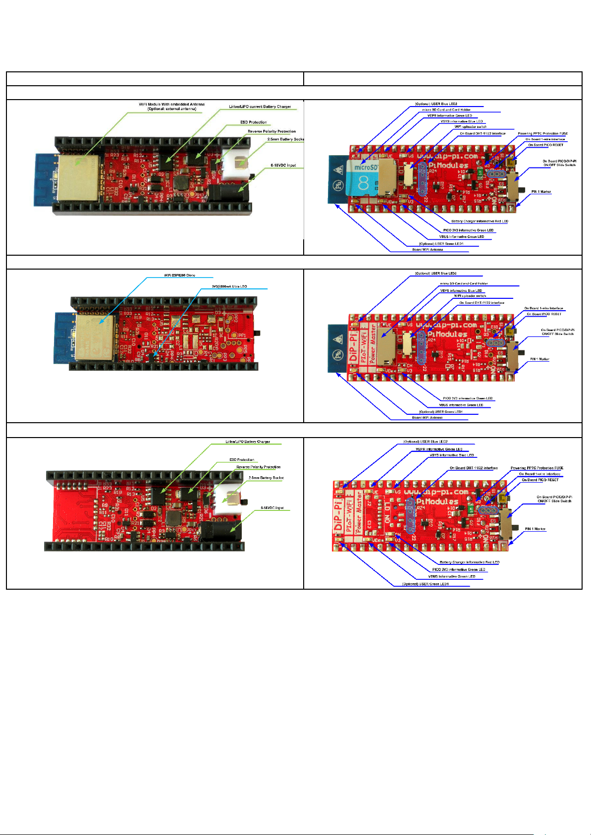
Top Side
Bottom Side
DiP-Pi PIoT Full
DiP-Pi PIoT WiFi Master
DiP-Pi PIoT Power Master
Table 5 DiP-Pi PIoT Moldels
Hardware Interfacing/Interaction with Raspberry Pi® PICO
The core goal of the DiP-Pi is to minimize pins required to be interfaced with and left them for user
applications. Therefore, for WiFi interfacing has been selected Serial Port of Raspberry Pi PICO and AT
Commands instead of SPI, for micro-SD Card single line SPI (not 4 bits), as also A/D Pins if not used
for monitoring of are bridged by 0402 0R resistor that in a case user does not need it, can be easy
removed. The 1-wire and DHT11/22 interfaces if not used for their scope, can be used by user
application. A detailed usage of Raspberry Pi PICO Pins is presented for each model on Table 6 DiP-Pi
PIoT Moldels
Designed and Manufactured by www.pimodules.com

Battery Connection
The DiP-Pi PIoT Full and DiP-Pi PIoT Power Master both are equipped with UPS functionality and
allow to use connected external battery. Used Battery must be PCM protected, and protection must
not allow current higher than 2 A. There is also needed to take a special care how to connect battery
polarity to avoid miss working or destroying of the device. There are special makers on the PCB
showing where should be connected “+ “ and “–“ of the battery. Battery can be used independently
from the Cable powering and can be switched ON/OFF with the slide switch for battery powered
applications as also as automatic power backup UPS functionality.
Figure 9 Battery fitting
Extended Powering Cable Connection
The DiP-Pi PIoT Full and DiP-Pi PIoT Power Master are offering to be powered also with Extended
Powering Input (6-18V DC). This EPR input can be used for industrial applications powering. It is
reverse polarity, ESD and PPT fuse protected.
The power input is done via Socket, DC Supply, male, Contact size 3.4/1.3mm or 3.5/1.3mm. The plug
is included in the package. Polarity should follow below diagram.
Figure 10 EPR Plug Soldering
Designed and Manufactured by www.pimodules.com

ON/OFF Slide Switch and Reset Switch
The DiP-Pi PIoT Full, DiP-Pi PIoT WiFi Master and DiP-Pi PIoT Power Master are equipped with
ON/OFF Slide Switch and PICO RESET Button. It switches power of the Raspberry Pi PICO ON/OFF
on all power sources (USB, EPR and Battery). The position of the slide switch moved to the PIN 1 side
make the system Powered as shown on the below picture. If system is powered by USB can be used
for firmware download instead of removing the USB cable. The PICO RESET Button is connected
directly to the Raspberry Pi® PICO Reset pin, and when pressed resets the Raspberry Pi® PICO and
can be also used as alternative for the firmware download instead of removing the USB cable.
Details are shown on the picture below.
Figure 11 ON/OFF Switch Positioning
UPS Functionality
The UPS Functionality is an integrated part of the powered DiP-Pi PIoT versions (DiP-Pi PIoT Full and
DiP-Pi PIoT Power Master). It is automatic and whenever cable powering is missing it is automatically
switching to battery and vice-versa. The UPS Functionality is working when ON/OFF Slide switch is on
Position ON. Whenever used system can be switched OFF with their Slide ON/OFF Switch.
Embedded Li-Ion LiPo Charger
The DiP-Pi PICO PIoT Full and Power Master are equipped with embedded I-Ion and LiPo charger. It
is working automatically and charging battery when needed. When Battery is charged then the CHG
LED is ON, when battery is not connected or faulty the CHG LED is blinking.
Connectivity with Raspberry Pi PICO:
● BATLEVEL ADC0 (GP26) measures Battery Level
● CHG_ACTIVE (GP21) activate/deactivate Battery Charger
ESP8266 WiFi Embedded Module
The DiP-Pi PICO PIoT and WiFi Master are equipped with embedded Integrated ESP8266 clone
(WT8266). It is handled by AT Commands, and practically can be used for all of the WiFi Applications.
They include simple interactive WEBSERVER, email client, UBIdots client, data access to SD card
logger etc. The default speed of the AT Commands is 115200 bps. The range of baud rates
supported: 110~115200*40.
Designed and Manufactured by www.pimodules.com

Connectivity with Raspberry Pi PICO:
● UART0RX(GP13)
● UART0TX(GP12)
● WiFi Reset (GP15)
● WiFi ENABLE(GP11)
Figure 12 WiFi Module
WT8266 WiFi Embedded Module AT Commands Set
The WT8266 AT Commands detailed specification can be found in different manual listed here
WiFi Firmware Uploader switch
The Uploader Switch is used to upload the newer firmware (only if really needed – under normal
conditions NOT needed) for WT8266 WiFi Module. Under normal usage should be on position NO
(NOrmal). If it is on position LD (LoaD) the WiFi Module will not working properly as will be waiting
for new firmware. The update switch is connected directly to the WT8266 WiFi Module.
Designed and Manufactured by www.pimodules.com

Figure 13 micro-SD Card and WiFi
Micro SD Card Socket
Is used to hold data, or Raspberry Pi® PICO executable software. Therefore, allow user to execute
micro-python directly from it. Above picture shows the micro-SD Card inserted.
Connectivity with Raspberry Pi PICO:
● SD_MISO (GP16)
● SD_CS (GP17)
● SD_CLK (GP18)
● SD_MOSI (GP19)
● SD_DET (GP20)
Informative LEDs
The DiP-Pi PICO PIoT is equipped with multiple Colored Informative LEDs. They are:
● VE – ON when VEPR 6-18VDC is applied (Green)
● VS – ON when VSYS is applied (Blue)
● VB – ON when VBUS is applied (GREEN)
● V3 – ON when V3V3 is generated (GREEN)
● CH – ON when VCHG is generated (RED)
Designed and Manufactured by www.pimodules.com

Figure 14 Informative LEDs
DiP-Pi PIoT Interfaces
Each DiP-Pi PIoT Modules is equiped with with some basic intefaces. There are:
● A/D inerface that measure Battery Level (where is implemented – Version Full and Power
Master)
● A/D inerface that measure EPR Level (where is implemented – Version Full and Power
Master)
● 1-wire embedded Intreface ESD Protected (all versions)
● DHT11/22 embedded Intreface ESD Protected (all versions)
A/D interfaces
Two of existing Raspberry Pi PICO A/D are used by the DiP-Pi. They are:
● BATLEVEL ADC0 (GP26) measures Battery Level
● EPRLEVEL ADC1 (GP27) measures EPR (6-18VDC) Level
Both are equipped with serial 0402 0R Resistor that can be easy removed if this functionality is
not needed. Both A/D are based on Resistor Dividers to cover PICO limited voltage inputs.
Designed and Manufactured by www.pimodules.com

A detailed examples how to read A/D data and convert to voltages as also implementation of
Olympic Score de-noising filtering algorithm are provided here.
1-wire interface
The DiP-PIoT is equipped with 1-wire interface. It contains resistor 4K7K as also ESD protection. This
interface can be used with temperature sensors and i-button (making sophisticated lock systems).
Due to reduced available space the sensor needs to be soldered to DiP-Pi PIoT. If user do not have
soldering skills our company is offering the soldering service.
Figure 15 1-wire interface
Connectivity with Raspberry Pi PICO:
● 1-wire data (GP10)
The 3V3 powering for the 1-wire interface is provided by DiP-Pi from a separate protected LDO
@600mA, therefore there is no risk if short circuit.
A detailed examples in micro-python are provided here.
Designed and Manufactured by www.pimodules.com

DHT11/22 Interface
The DiP-PIoT is equipped with DHT11 or 22 interface. It contains resistor 10K. This interface can be
used with temperature/humidity environmental sensors for application like weather station. Due to
reduced available space the sensor needs to be soldered to DiP-Pi PIoT. If user do not have soldering
skills our company is offering the soldering service. DiP-Pi PIoT is supporting also cabled sensor co
can be placed away of the system.
Figure 16 DHT11/22 Interface
Connectivity with Raspberry Pi PICO:
● DHT11/22 data (GP22)
The 3V3 powering for the DHT11/ 22 interface is provided by DiP-Pi from a separate protected LDO
@600mA, therefore there is no risk if short circuit.
A detailed examples in micro-python are provided here.
Ready-To-Use Examples
Library and Ready-to-Use examples can be downloaded from here.
Common Problems & Solutions
Can I connect EPR (6-18VDC) input and Raspberry Pi PICO micro-USB at the same
time?
Yes, you can. They are electrically separated and can be used at the same time. The ENTRY point for
the EPR (4.8V) is the VSYS, so they are separated by diode on the Raspberry Pi PICO.
Designed and Manufactured by www.pimodules.com

When I switch OFF with the Slide Switch and micro-USB is connected, the VUSB and
is still light.
It is normal, as the VUSB (VB) LED is powered via VUSB so as far the USB is connected the LED is
powered. Similar with VSYS, as is originated form the VUSB. The OFF signal (LOW) is attached to the
Raspberry Pi PICO OFF pin, that cause stopping of Buck/Boost converter working. Therefore, when
powered by micro-USB the ON/OFF witching will cause V3V3 voltage LED (V3) switching.
Document Revisions
Version
Date
Modified Sections
Comments
N.A.
01/09/2021
N.A.
First Preliminary Public Document Release
DiP-Pi PIoT Schematic
Designed and Manufactured by www.pimodules.com

Figure 17 Detailed Schematic
Designed and Manufactured by www.pimodules.com
 Loading...