

FreeX MANX S, MANX M, MANX L Owner's Manual
Owner's manual

Important notice
All technical data in this manual has been worked out very thoroughly by the
authors. In spite of this, errors cannot always be excluded. FreeX and the dealer do
not accept any kind of liability for
any casualties or damage caused directly or
indirectly by the use of this equipment or due to imperfect information. The authors
warmly welcome any comments, suggestions or information about possible
inaccuracies at any time.
We reserve the right for chang
es occurring due to technical progress.
Trademarks
The quotation of brand names, trade marks and trade names etc. in this manual,
even though not being specially marked does not justify the assumption that such
names can be considered as free in the sens
e of the existing trade mark protection
law and hence be used by everyone.
freeX is a registered trademark by FreeX GmbH.
Copyright
© 200
7
by FreeX GmbH.
All rights reserved. No part of this publication may be reproduced or transmitted in
any other way s
ave with written permission of FreeX GmbH.
revision
: 10.07.2008

3
Congratulations
on the purchase of your freeX MANX!
You have made an excellent choice. We wish you lots of great
flights and just as many safe landings with your new wing!
In order to make yo
ur start as easy as possible and to help you
get familiar with your MANX and its advantages, we recommend
-
before you intend to get airborne with your MANX
-
that you
read these instructions very carefully and pay attention to the
data given.
Your freeX
-Team
info@freex.com
www.freex.com

4
Registration
6
Technical Data
6
Personal requirements
7
Description of your flying equipment
7
The MANX in detail
8
The canopy
8
The line system
9
The riser system
10
The speed system
11
Suitable
harnesse
s12The reserve parachute
13
The carrying bag
13
Possibilities for adjustment
16
Brake
16
Speed system adjustment
18
Flying
22
Launching
22
Preparation
22
Launching technique
24
Winch towing
24
Flight tech
nique
25
Speed control
25
With the brakes
25
With the speed system
25
Turning
26
Flying in thermals
26
Flying in turbulence
27
Fast descents
28
Spiral dive
28
B-line Stall
29
Big-ears
30
Landing
30

5
Extreme flight manoeuvres
31
Aerobatics
31
Deflations
32
Asymmetric deflations
32
Collapse with entanglement
32
Front deflations
33
Stall
34
Deep (parachutal) stall
34
Dynamic / Full stall
34
Spin
35Brake failure
35Motorised flight
36
Care and Maintenance
36
Safety instructions and liability
38
Appendix
39
6
Registr
ation
Technical data
freeX is very interested in keeping you up to date in an optimal
way about technical progress and providing you with the latest
information concerning your MANX. In order to do so, we kindly
ask you to r
egister with us by filling in and returning the attached
reply card. In order for us to provide you with the best possible
support, it would be very helpful if you would also answer the
questions on the back of the reply card.
MANX
SML
Startweight
kg60-8580-105
100
-
130
Cells
363636
Glider weight
kg
5,2
5,2
5,2
Area
m2
25,82
28,94
31,58
Span
m
11,40
12,06
12,60
flat
Aspect ratio
5,03
5,03
5,03
Area
m2
22,20
24,86
27,15
Span
m
9,05
9,57
10,01
projected
Aspect ratio
3,69
3,69
3,69
Lines (A/B/C/D)
3/4/3/3
3/4/3/3
3/4/3/3
V-Trimm
km/h
36,00
3636V-Max.
km/h
505050
Sink rate
m/s
1,15
1,15
1,15
Certification
DHV1
DHV1
DHV1
Tow
JaJaJa
7
Personal Requirements
Description of your flying equipment
The freeX MANX has successfully passed the most string
ent test
worldwide and achieved the German DHV
-
Gütesieg
e
l registration
with
LTF 1.
It is suitable for flight training and for the less experienced pilot.
The only frequently flying leisure pilot will also find a perfectly
suited glider in the MANX. It’s un
complicated flight behaviour
allows you to adjust quickly to your new glider. Thus, you can
begin to benefit from the Manx high performance potential early
on, and can set higher goals for all flights.
Even the experienced pilot will derive sheer pleasure
from the
MANX. Its great speed range and high performance potential,
combined with its direct and easy handling make the MANX the
perfect partner for excellent results and more flying fun.
Before starting, however, it is important from the standpoint of
s
afety that you get sufficiently familiar with your new equipment
by reading this manual and by spending time with your glider on a
practice hill. We particularly urge you to make use of the chapter
dealing with Possibilities for adjustment.
The MANX is th
e result of a complex development by the freeX
-
development team, while integrating latest findings in paragliding
aerodynamics and material studies. The outcome is a fast, stable
entry level glider of the highest quality, which couldn't be easier to
launch
, is stable when aloft and sets new standards in handling
and flight performance.
With your MANX you have purchased a glider which is made
according to the latest level of technology, and the dimensions of
which fulfil the harshest demands in all aspects.

8
The MANX in Details
The canopy
Caution: At the time of dispatch, each MANX corresponds to the
certified version. Any arbitrary change beyond the registered
adjustment possibilities (see appropriate chapter) dangerously
affects the flight behaviour and is prohibited!
The canopy of t
he MANX is made of extremely strong, especially
coated Porcher Marine fabric which when treated properly (see
chapter Care and maintenance) has proved to be extraordinarily
wear
-
resistant and airtight, so that you will enjoy safety and
excellent resale val
ue of your MANX for a long time.
The top surface is produced with our new Hybrid technique, with
the first third being made up with the 9092 E85A 44g material,
while the latter two thirds made up with 9017 E77A 40 g material.
This well tested Material
-
Mix
guarantees a high quality, longer life
and a higher class of safety due to the overall lightness to the
canopy. Both materials are impregnated in a water repellent
coating which helps maintain the porosity for a longer period.
The bottom surface uses the 9
017 E38A 40g material which
again optimises the overall weight of the glider.
Diagonally stiffened Porcher Marine fabric 9017 E29A (Hard
finnish) was our choice for the profile and ribs in order to
guarantee maximum profile accuracy in connection with the
load
optimised force penetrations for induced forces. The profile of the
MANX was particularly calculated for the demands of a modern
paraglider by the aerodynamics specialist Dani Loritz and shows
an unusually high range of angle of attack.
Leading and tr
ailing edge are reinforced with a polyester band, air
intake holes and partly closed cells are stiffened for best
attributes for launching and high speeds.
The round shape of the cell openings as well as the partially
closed cells were chosen to guarantee
a balanced tension ratio
between upper and lower surface and at the same time to keep
the openings at the leading edge which normally are
disadvantageous to performance as small as possible.
The MANX is not equipped with a stabilizer in the traditional
sen
se. It has been reduced to a winglet of the smallest possible

9
The line system
dimensions. In this way induced drag has been reduced and the
MANX has been provided with high directional and canopy
stability without bringing about unnecessary parasitic drag.
The centre pro
file on the bottom surface has been enlarged in
comparison to the others, as a result gives a thicker flying profile
in the middle of the wing, known as the so
-
called Kiel Rib. This
Kiel
-
Rib reduces Roll and Yaw and improves the turning
momentum of curves.
The overall result is a more flat and
smoother turning, which improves the ability of climbing in
thermals as well as turns close to the ground.
The Kiel
-
Rib also reduces the Yaw and Roll momentum by
collapses by max 50%.
The parasitic line drag has bee
n minimized by bifurcating
(branching) the lines between canopy and riser at three levels
and by adapting their diameters to the occurring loads. Only high
-
quality Cousin Trestec, Super Aramid and dynema lines are used.
These high
-
tech
-
lines meet the highe
st requirements of a
paraglider line in a special way: The outstanding tension stability
ensures that line lengths still show original figures even after long
use; thus dangerous alterations of flight features by different
tensions are excluded. At the sam
e time, kink resistance passes
highest test standards.
The line groups A, B, C and D each lead separately to the
appropriate riser, making it possible to access each set of lines
separately, for example when B
-
lining (see the section on
techniques for desc
ending). The stabi is attached on the B
-
level.
Additionally there is a seperate Baby A
-
riser. This is for easier
application of the manoeuvre “Big
-
earing”. A, Stabi and brake
lines are Yellow. B, C and D lines are Red.

10
The Riser system
The riser
The 4 riser system of
the MANX is adjusted to a uniform length
of 47cm (L50cm) adjusted. This allows uncomplicated handling
when launching as well as the ability to reach line links during
flight. The precisely designed transmission ratio of the riser
system is adapted to the p
rofile and combines a reduction of
angle of attack with a decrease of arch upon accelerating via the
foot bar.

11
The speed system
For quicker identification of risers, the colour of the seam tape on
the A
-
riser is yellow, and on the B
-
risers is red (=emergency
manoeuvre, B
-
Stall).
The brake/control line is guided by a pulley. It is attached to a 6
cm long extender in order to give the pilot more space when
operating the brakes without adversely affecting D
-
lines.
The final adjustment of the toggle position must take into ac
count
measurements of harness, pilot size and his/her individual
preferences (see chapter Possibilities for adjustment).
The speed system
The speed system of the MANX consists of two parts: The
transmission system of the risers which distributes the
action to

12
Suitable harnesses
the separate line
-
groups, and the pulley system on the A
-
riser
which gives a 3:1 reduction and allows the full 10 cm (Size M 12
cm) of travel on the A
-
riser of the MANX to be used without
excessive effort.
Connecting the footbar to the speed
-
sys
tem are C
-
clips on the
accelerator cord and on the riser. These are simply twisted
together before takeoff with a 90
-
degree movement.
By profile
-
specific shortenings of the A
-
B and C
-
risers, the
MANX is accelerated very effectively by about 14 km/h without
decisively sacrificing stabil ity.
The cord from the foot
-
bar runs as usual through one or several
pulley
-
rollers on the harness to the front and must be connected
with appropriate length to the included foot bar.
The MANX was designed for use with any
licensed harness, like
the FreeX Carrera. Extremely stiffened cross
-
strap
-
harnesses
with very high suspension may, however, adversely affect the
handling of the MANX and its behaviour during spiral dive (see
chapter Fast descents!).
The MANX is authorised
for use with most modern paragliding
harnesses. As optimal configuration, we recommend the use of a
harness with medium to low hang
-
points in order to make full use
of weight shift when turning, which the MANX reacts to very
easily. For the maximum in pass
ive safety, freeX recommend the
use of a harness with back
-
protection and an under
-
seat
-
mounted reserve container. The freeX Carrera is a modern
harness with DHV
-
approval and is ideally suited for use with the
freeX MANX. Contact your freeX dealer for more
information.
Please remember that the suspension level of your harness
transmits into the adjustments of the control/brake line lengths
and of the speed system (see chapter Possibilities for
adjustment)!
13
The reserve parachute
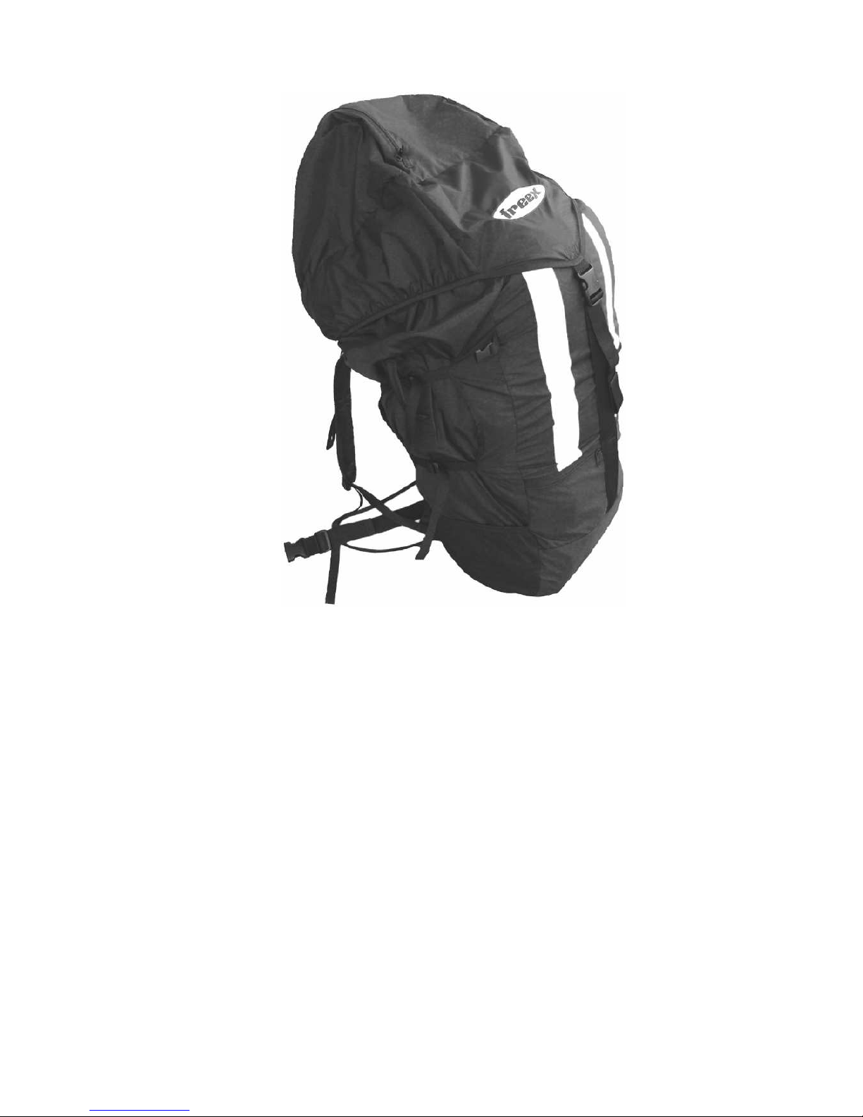
The carrying bag
Carrying a licensed safety chute is part of the
safe use of a glider
even when the risk of equipment failure can be considered to be
negligible. When choosing the appropriate rescue system of the
right size, please apply the same care as you did when you
picked out your freeX paraglider!
The reserve sy
stem LR34 and LR39 from FreeX are a modern
round canopy with a central line to eliminate pendulum
momentum. The opening time and sink rate are of the minimum.
We have created a new generation of backpacks, which improve
greatly on standard models in many
details.
The freeX packsack is sufficiently large, in order to accommodate
the largest of equipment. Special geometry and weight
distribution ensures an outstanding comfort. The durable nylon
material and the complex processing ensure an unusual
longevity.
If the volume is not fully used, then the bag with the
four lateral compression belts can be tightened. Note: Always
remember to open compression belts before the Backpack is
packed! Apart from the enormous capacity, the freeX comfort
packsack possesses a
nother large top flap, into which helmet,
overalls, gloves etc. can be stowed away.
Also modern
harnesses with large back protectors find place.
14
The backpack
First, helmet and vario meter, gloves and similar objects are
stowed away into the padded lid p
ocket with access from outside.
This way they are protected from pressure coming from outside
and there is no risk of them sliding into your back.
Then the canopy itself is pushed into the main compartment.
Even huge harnesses with dorsal protectors are ea
sily stowed
upside down with the seat above the canopy. The zippers allows
closure of the backpack without effort or strain.
Flying suit, jacket and other clothing can be packed in the lower
pocket. The flat outer pocket of the lid is designed for maps,
la
unch information, etc. The position of the small elliptical side
-
pocket makes it easy to reach wallet or sunglasses without
having to take off the backpack.
15
The freeX backpack derives its optimal comfort in carrying even
for longer hiking tours from the d
orsal foam insertion and the
efficient hip
-
belt.
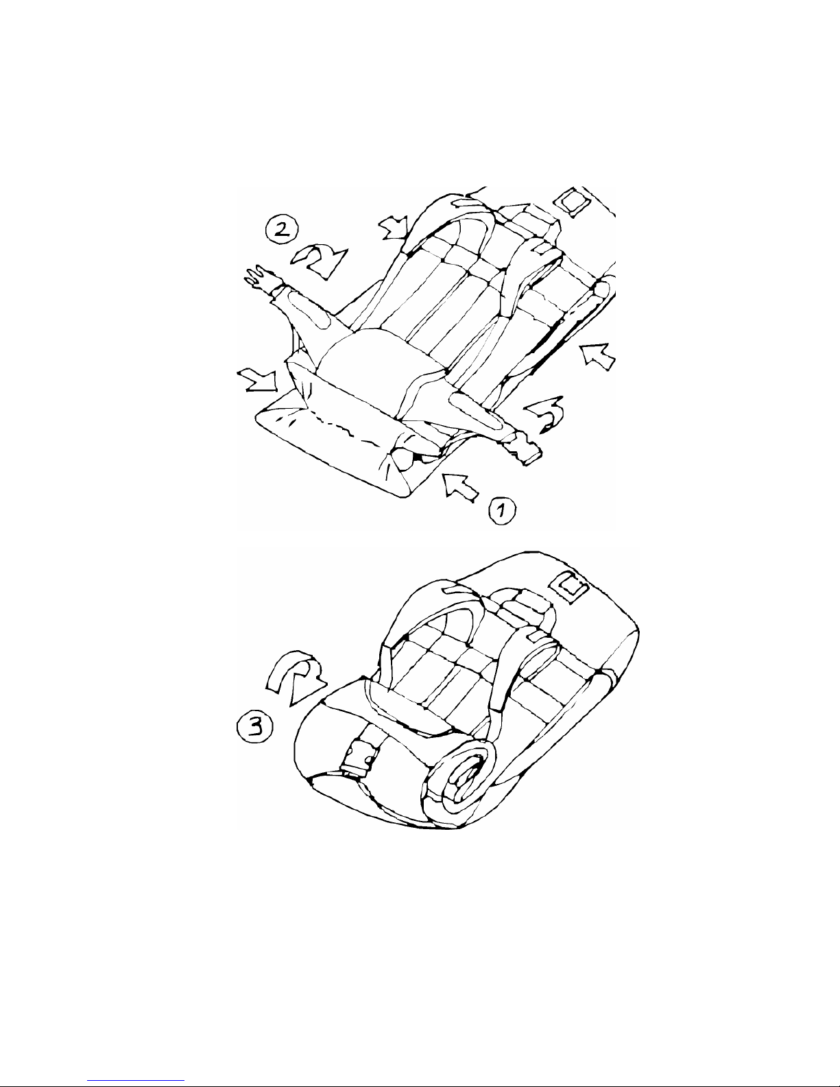
The empty bag can be easily folded up in order to pack away into
the harness.
Simply follow the diagrams below:
Foldingof bag 1
Folding of bag 2
16
Possibilities for adjust
ment
Brake
The manufacturer has set all line and riser lengths
of the MANX
with high precision to the tested measurements as standard. In a
multi
-
phased process for securing quality every paraglider is
rechecked individually before leaving the manufacturer.
Therefore, there is no need for readjustment or fine trimming
.
Your MANX has been set optimally regarding flight performance,
handling and safety.
Any arbitrary alteration of line lengths or risers will result in the
expiry of any responsibility of the manufacturers or distributors!
Exceptions to this are adjustmen
ts of brake position and speed
system.
The brake line adjustments of the MANX at the time of its serial
dispatch are the medium position.
This length adjustment may never be shortened, which means
the brake toggle may never be set at a position which is m
ore
than 5 cm higher! The result would be a continuously slowed
-
down canopy. Please note that through drag the brake already
transmits power before it looks tight in the pilot's eyes!
At the time of dispatch, the brake adjustments have a neutral path
of ab
out 10cm. This adjustment is more apt for practice since it
does not involve the risk of slowing down the canopy
unintentionally. The marking on the steering line corresponds to
this adjustment and should not be set below if possible!
Warning!
In no case m
ay the position of the steering lines be
shortened by more than 5 cm relative to the marking applied!
The MANX exhibits comfortable handling with medium brake
distances. It shows a progression of brake forces (increase of
forces with brake distance). It is
therefore important that every
pilot makes the best adjustments according to his size, harness
combination and personal preferences in order not to tire rapidly
by a non
-
ergonomic position of the brakes.
The region between shoulder and chest is inefficien
t for muscle
power input; this is a transitional region between pulling and
pushing for the arms.
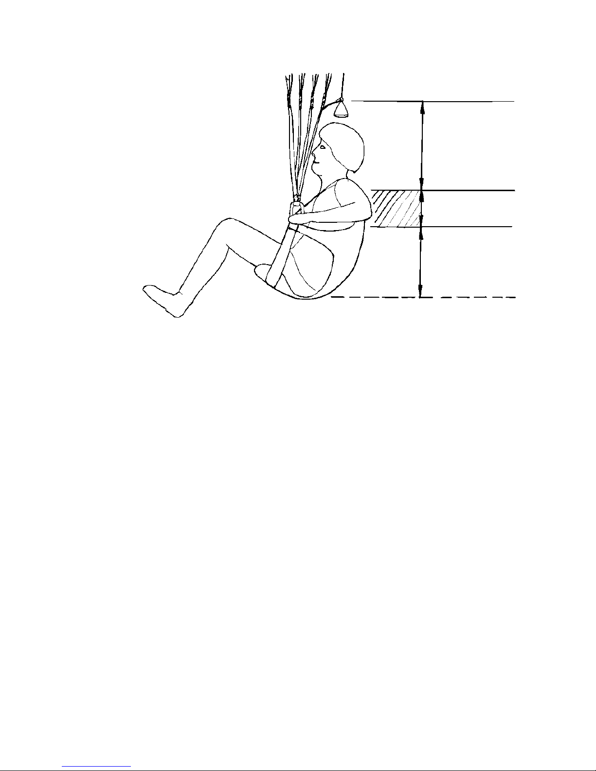
17
Brake adjustment
Thus, this region should be avoided as the main control area and
in harnesses with low suspension or with very tall pilots this is
achieve
d by elongation of steering lines. Since not enough
distance is available above the shoulder (region of pull), the brake
zone must be shifted into the pressure zone (region of push).
Pilots who are smaller or whose harness is attached at a higher
level, us
ually have the choice, following their own inclination, to
retain the brakes at their shortest position and to control within
the region of pull (above the shoulders) or to adjust the brakes to
a significantly longer position and to steer within the lower
arm
position below the chest.
The brake distance must in any case allow the MANX to be
stalled upon landing without taking wraps. This can also happen
dynamically (while taking advantage of the pendulum effect).
Coiling the steering lines around the hands
is not recommended
since the pilot's ability to interpret the stall point is lost (shifting of
reference point), the blood flow to the hands is blocked off and in
the case of having to use the safety chute the throwing hand is
simply tied.
If you wish for
a tighter connection to the toggle you should better
use the "ski
-
stick" method (slide the hand through the toggle with
palms up and grab toggle from behind at the D
-
ring).
 Loading...