

R
This manual covers all color schemes
Although it only shows one color scheme, the aircraft are the same
This manual is for reference to the actual product at the time it was written. We can't speak
for any future upgrades or improvements
R
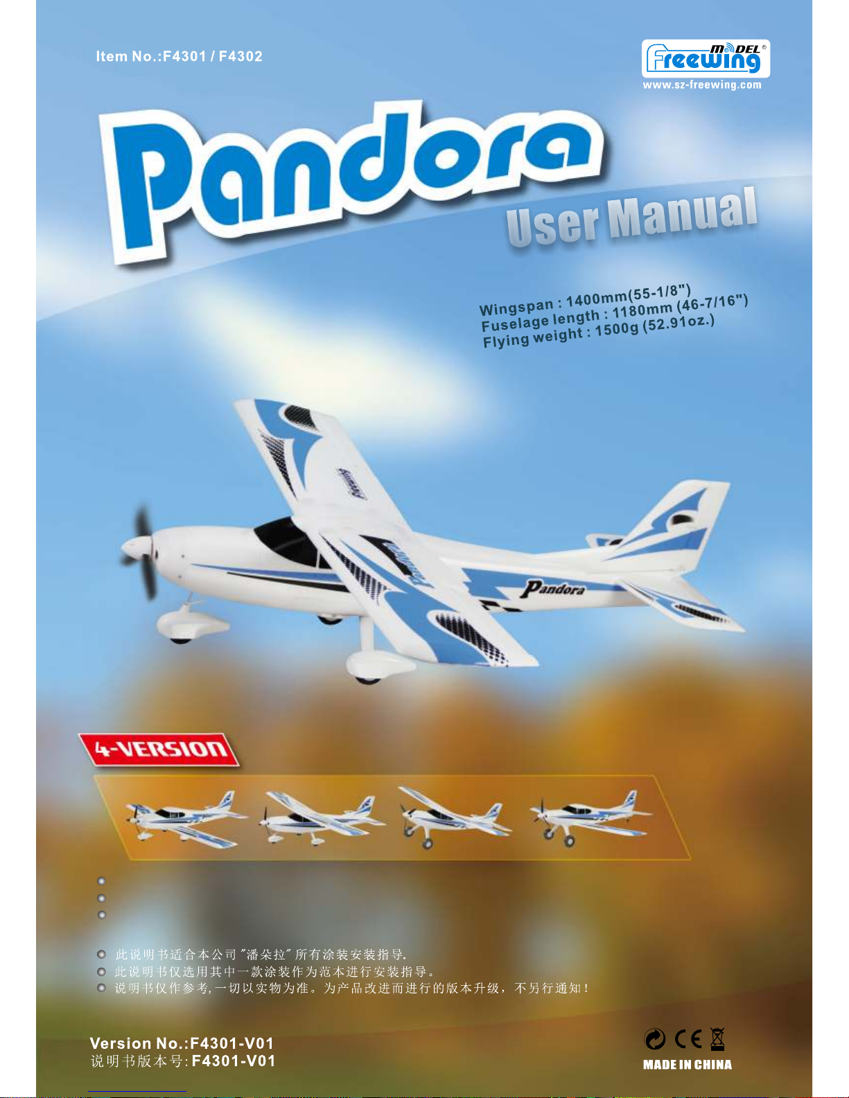
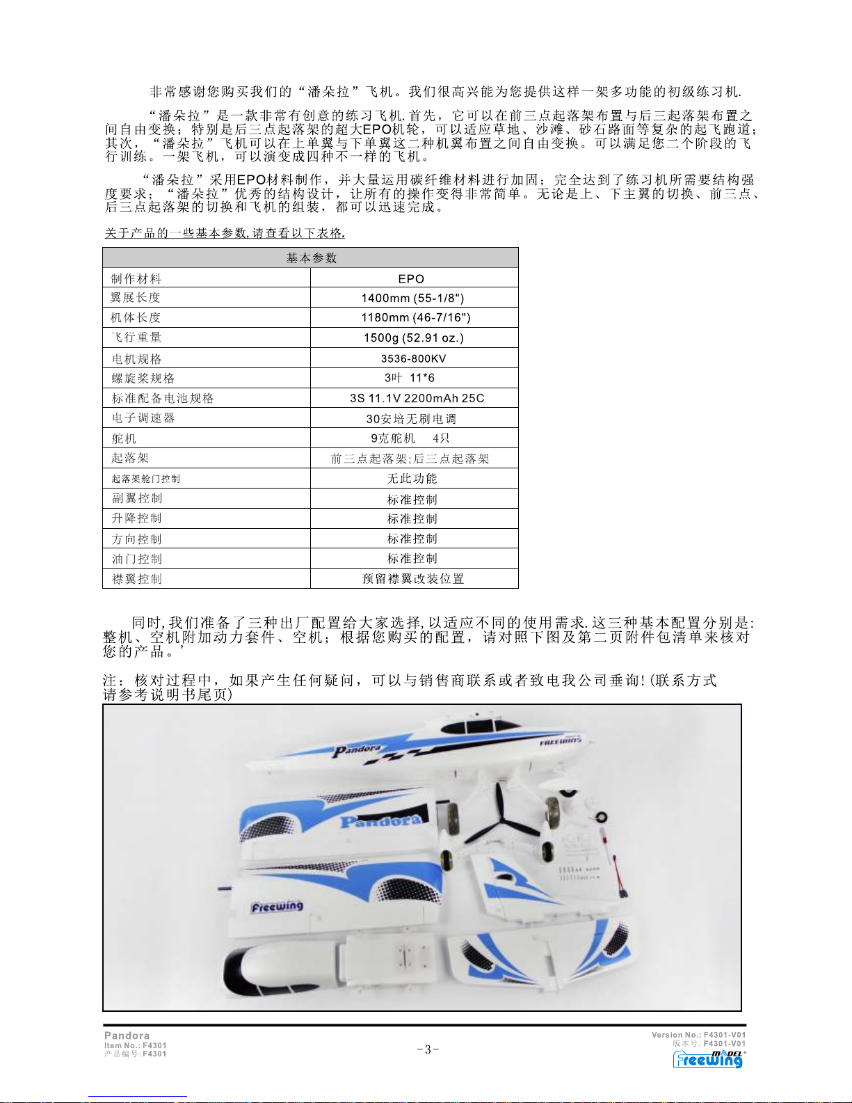
Thank you for purchasing the Freewing Pandora 4 in 1 training aircraft! We're extremely
pleased to be able to provide you with this extremely popular multi-functional aircraft, just listen
to what you have purchased! First, the Pandora is a super stable and well thought out airplane,
but the thing that sets it apart is that you can fly it in high wing/ low wing tail dragger, or in high
wing/low wing tricycle landing gear configuration. Four planes in one! Changing over from high
to low wing and tricycle gear to tail dragger is quick and can easily be done right at the field!
The Pandora is completely capable of taking off from grass runways and even beaches!
Freewing has utilized EPO foam and carbon fiber reinforcement to take the punishment a
new pilot can inflict.
Although she is classified as a trainer, this is an airplane that you'll be flying long after your
skill set has let you move on to higher performance airplanes, just for the fun of it!
So, all set to assemble your new airplane? Let's get you in the air!
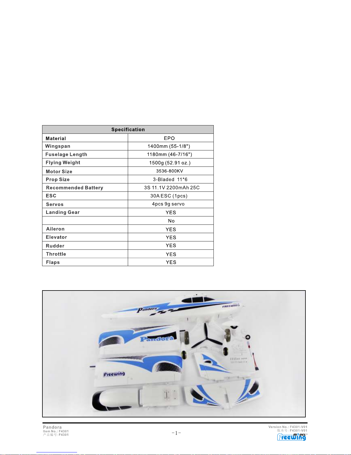
Basic specifications of the Freewing Pandora
Retractable landing gear
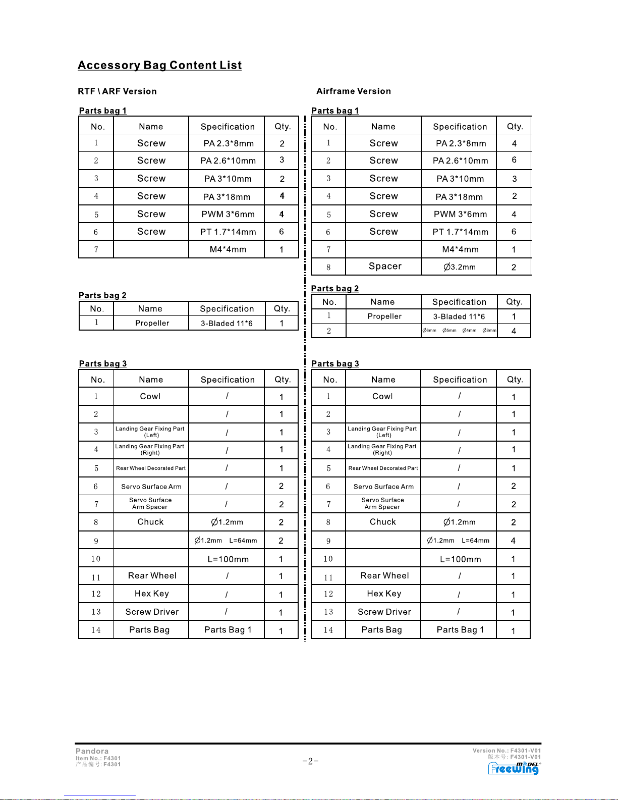
All the parts and pieces needed to fly in all four configurations are provided with this RTF,PNP aircraft kit. Ensure
that all the parts shown in the picture below have been provided with your kit.
R
Grub Screws
Grub Screws
Propeller back plate
Servo extension
cable
Servo Extension
cable
'Y' cord
'Y' cord
Spinner
Spinner
R
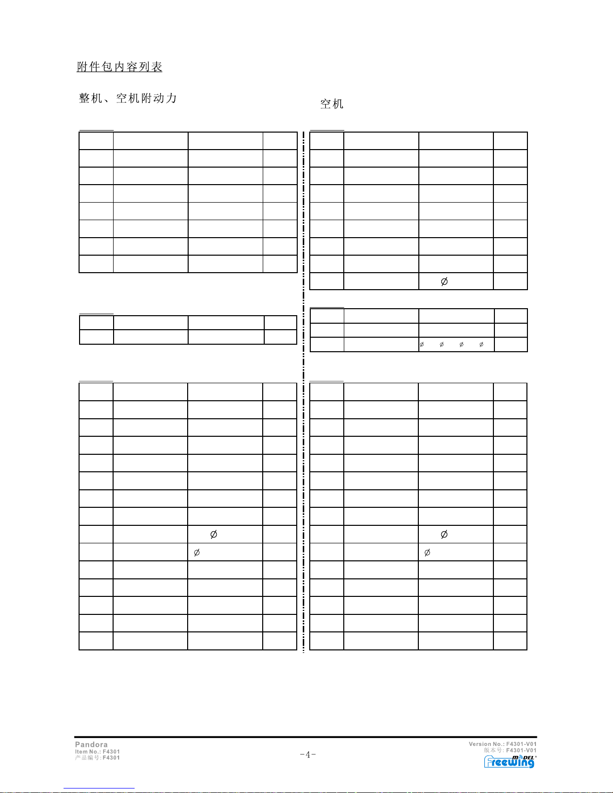
附件包 1
附件包 2
附件包 3
1
螺旋桨
3叶 11*6
1
1
2
3
4
5
7
2
2
1
1
1
6
6
3
4
4
PA 2.6*10mm
PA 3*10mm
PA 3*18mm
PWM 3*6mm
PT 1.7*14mm
机米螺丝
M4*4mm
螺丝
PA 2.3*8mm
1
2
3
4
5
7
8
6
9
10
11
13
14
12
整流罩
螺旋桨固定盘
起落 架固定塑料 件(左)
尾轮塑料件
舵面遥臂
舵面遥 臂固定片
Y
EVA尾轮
/
/
/
/
/
/
/
/
/
/
L=100mm
1.2mm
1.2mm
L=64mm
1
1
1
2
1
1
2
2
2
1
1
1
1
1
1
1
1
2
3
4
5
7
4
3
2
4
1
6
6
6
PA 2.6*10mm
PA 3*10mm
PA 3*18mm
PWM 3*6mm
PT 1.7*14mm
M4*4mm
PA 2.3*8mm
1
2
3
4
5
7
8
6
9
10
11
13
14
12
/
/
/
/
/
/
/
/
/
/
L=100mm
1.2mm
1.2mm
L=64mm
1
1
1
2
1
1
2
2
4
1
1
1
1
1
8
3.2mm
2
螺旋桨定位圈
2
6mm 5mm 4mm 3mm
4
螺丝
螺丝
螺丝
螺丝
螺丝
序号
配件名称
规格参数
数量
序号
配件名称
规格参数
数量
序号
配件名称
规格参数
数量
起落 架固定塑料 件(右)
夹头
主翼舵机钢丝
线
内六角扳手
螺丝刀
零件包 零件包1
机米螺丝
螺丝
螺丝
螺丝
螺丝
螺丝
螺丝
垫片
序号
配件名称
规格参数
数量
序号
配件名称
规格参数
数量
螺旋桨
3叶 11*6
序号
配件名称
规格参数
数量
整流罩
螺旋桨固定盘
起落 架固定塑料 件(左)
尾轮塑料件
舵面遥臂
舵面遥 臂固定片
EVA尾轮
起落 架固定塑料 件(右)
夹头
主翼舵机钢丝
线
内六角扳手
螺丝刀
零件包 零件包1
附件包 1
附件包 2
附件包 3
R
R
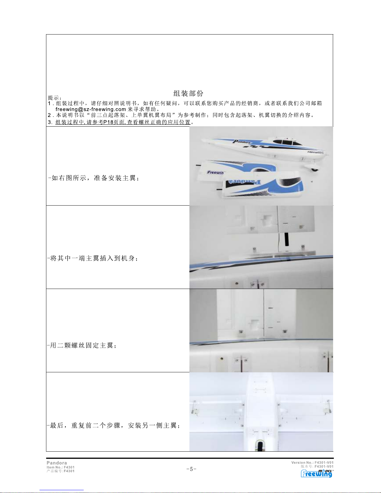
Assembly
Note:
1. Read the manual carefully before beginning assembly and make sure you understand each step in the
process. If you have any questions, contact your distributor, or contact us at freewing@szfreewing.com.
2. As a reference, this manual will assemble the airplane in the high wing tricycle landing gear
configuration as well as explain how to reconfigure the airplane afterwards.
3. Before assembly, please refer to P 18 for proper screw assignments.
Find the parts (see the photo) needed to install the
wing onto the fuselage.
Feed the servo wire through the hole in the center
section, then slip the carbon fiber rod into the round
hole in front of the wire hole and slide the rod up so
that the attachment points are visible through the
points on the wing. Make sure that the servo wires
are not pinched between the wing and the center
section.
Anchor the wing to the center section with the two
provided screws. Do not over tighten the screws!
Repeat these steps for the other wing.

R
Find the parts shown in the photo to assemble the
landing gear.
Insert the main landing gear assembly into the
attachment point on the underside of the fuselage.
Insert the two plastic landing gear retainers and use
the provided screws to anchor them to the landing
gear attachment point as shown in the photos.
The completed assembly.
Place the horizontal stabilizer onto the fuselage and
the slide the vertical stabilizer over it and into it's
position on the fuselage as shown in the photo.

R
Using the two screws, anchor the
assembly to the fuselage. Notice one
screw hole is located about half way up the
length of the horizontal stabilizer and the
other is beyond the leading edge of the
stab. See the photo.
The propeller backing plate slides over the motor
shaft then the propeller, followed by a washer, then
the retaining bolt snugs the prop and backing plate
to the aircraft. Ensure that the retaining nut is tight
so that the propeller is secure, but do not over
tighten it. Then slip the spinner over the prop and
secure it with the three provided screws. There is an
exploded diagram on P18 to use as a reference as
to how to assemble the propeller.
Loosen the four screws holding the wings to the
fuselage and remove the assembly.
Turn the wing assembly over and join the two
aileron servo wires with a 'y' cable as shown in
the photo.
Remove the battery hatch cover by pulling up on
the plastic tape
Note: It is advised that you install the
propeller after binding the aircraft and setting
the control surfaces. Propellers are very
DANGEROUS!

R
Attach all the servo leads to the receiver (sold
separately) as shown in the photo. Afterwards, power
up the radio and plug a fully charged battery into the
ESC. Ensure that your throttle control is at it's lowest
position! If the ESC is not bound to the radio, bind it
now using the instructions provided with your radio.
Once bound you should hear three 'beeps'.
Center all the control sticks and trim tabs (Except
the throttle, leave it in the lowest position) on the
radio. Loosen the screws on the servo control
horns, then center to control surfaces of the
airplane. Once they are centered, tighten the
screws on the control horns back down. If needed,
the clevises can also be rotated to add extra length
to the control rods.
When all the surfaces are centered, reinstall the wing
assembly to the fuselage using the four screws,
tighten them securely but do not over tighten them.
Optional Flap Assembly
If you choose, you can add flaps to your Pandora.
You will need one standard and one reversed servo
and a Y harness (not included with the kit, see your
distributor).
Cut the two slots in the wing. DO NOT cut length
wise as this will remove the flap. Cut as indicated
in the photo.

R
Once cut, carefully bend the flap down and
back to neutral several times to loosen it up.
Remove the wings from the center section by
removing the four screws and sliding the wings
out.
After installing the flap servos, feed the servo
wires through the wire channels and into the
center section.
After the glue holding the flap servos in place has
dried, attach the control rods to the servo control
horns.
Join the two flap servo cables with a 'Y' harness
and plug the end of the 'Y' harness into an
available channel on the receiver.
Don't forget to plug the aileron cable back into the
receiver as well!

R
Reattach the wings to the fuselage and test the
flaps.
Changing from High Wing To Low Wing Configuration
Locate the parts as shown in the photo.
Remove the wing assembly from the fuselage,
ensuring that the flap and aileron 'Y' cables are
unplugged from the receiver.
Remove the four screws holding the wings to the
center section and slide the wings back.
Disconnect the 'Y' harness(es) from the servo
wires and completely remove the wing from the
center section
Take the low wing center section and slide the
wires through the holes, then slide the carbon fiber
rods into their holes.
Anchor the wings to the center section with the four
screws.
Join the two aileron (and flap, if installed)cables
with the 'Y' harness, just like in the high wing
configuration.

R
When the assembly is complete, it should look like it
does in the photo.
Turn the fuselage over and remove the detachable
lower piece that holds the tricycle main gear to the
fuselage.
Remove the main landing gear from this piece as well.
See the photo.
The low wing center section will be installed into the
slot where the detachable lower piece used to be.
Using the same four screws that held the
detachable lower fuselage piece in place, anchor
the lower center section to the fuselage.
Reassemble the main tricycle landing gear to the slot
on the lower center section and anchor it down using
the same hardware and screws that held it to the
removable power fuselage piece.

R
Feed the aileron and flap cables (if installed) through
the fuselage to the receiver and plug them in. When
securing the center section to the fuselage, take care
not to pinch the wires in between the two parts.
Install the canopy. It will snap into place as its held
on with magnets. Note the plastic strap on the
trailing edge of the canopy. Pull up on it to remove
the canopy to get access to the hatch.
Tail Dragger Landing Gear Assembly
Remove the spinner, propeller, backing plate and
the plastic cowling.
Remove the canopy and loosen the screw holding the
nose gear control rod inside the servo control arm's
anchor point. See the photo.
There are four screws that hold the nose gear onto
the fuselage, loosen these and remove the plate.

R
Remove the nose wheel.
Remove the main landing gear as well.
Get the tail dragger landing gear out
The main landing gear fits into the receiving slot on
the fuselage. just in front of the wing's leading edge.
You will have to pinch the piece a bit to slide it in
securely , Then screw the two tabs down over the
receiving slot as shown in the photo.
Slide the tail wheel wire into the plastic
mount as shown in the photo. Then this unit
attaches to the fuselage using two screws.

R
The tail wheel wire slides into the grub screw in the
fuselage. Line up the flat spot on the wire with the
screw and tighten it down.
Reinstall the cowling, back plate, propeller, washer,
anchor screw and spinner. Now your airplane
should look like the photo.
Battery Sizes
The recommended battery size is a 2200 mah 3s which will give you a 4 to 5 minute flight duration
using a mixed throttle. If you tend to use more throttle, the flight times will be reduced. In that case
you can go to a 2200mah 3s battery or higher as long as its 3s. Just make sure to reestablish your
CG as battery sizes will be different weights.
Battery Hatch Dimensions

R
The Center of Gravity is critical to achieve succ
essful flight. The Pandora is very forgiving but she has
her limits. The CG should be 70-80 mm back from the leading edge of the wing. Normally, a low
winged airplane will be balanced with the plane upside down and right side up for a high winged aircraft

R
Voltage
(V)
Before each and every flight, a new pilot must be aware of issues that may arise. These steps will help to ensure a successful flight.
1. The radio must be turned on first before ever plugging a battery to the ESC.
2. Before flight, check to make sure the ESC is functioning properly. Either anchor the plane down or have someone hold the
airplane by the tail and advance the throttle to ensure the RPM increases smoothly with throttle application. Do NOT stand in
front of the airplane!
3. Check your CG before flight, especially if you are switching between different types of batteries.
4. Always take off into the wind, whether hand launching or taking off from the ground.
5. Before flight, ensure that the control surfaces are moving in the correct direction.
6. After take off, gain altitude and get 'three mistakes' of height before leveling off. Then, when in level flight at about half
throttle, trim the plane to fly straight and level.
7. Set your timer to 4 minutes and land when the timer sounds that you are out of time. Check your battery and see how much
power you have left. You can adjust the flight times so that you have about 30% left when you land. Use caution, if you run
the
battery down too low, you will lose power and possibly control of the airplane.
8. Spare parts are available through your local dealer or go to www.sz-freewing.com, but many parts are repairable.

R
Transmitter and Receiver Operation
Note: The radio and transmitter are not
included with the kits and must be purchased
separately. Check with you local dealer for
more information.

6.0mm
R

R
 Loading...