

Freewing MIG-21 FISHBED, MiG-21 User Manual
www.sz-freewing.c om
0-14
MAD E IN CHIN A
M
I
I
G - 2 1
1/9 SCALE 80MM EDF JET
F I S H B E D
USER M A N UAL
LENGTH:1730mm
WINGSPAN:800mm
1
MI G- 21MF F IS HB ED
It em No .:F J210
Brief History
First designed in 1 95 3, t he MiG-21 is widely renowned as a classic Cold War er a brute and holds the distinction
of being the most produced supersonic jet fighter in the world. More than 11,000 MiG-21s of different variations
have flown for over 6 0 countries over a period of mo re than 60 years. In f ac t, the unmistakable outline of the Mi G21 can still be seen today in the sk ie s of ov er 15 countries that still oper at e this hi st or ic warplane. Th e MiG-21 ha s
earned its place i n av ia ti on h is to ry a s a versatile workhorse and venerable foe.
Overview
Dominate the ski es with Freewing’s 1/9 scale MiG-21! Its impressive 1730mm length makes t hi s MiG-21 one of
Freewing’s longest mod el a ir cr af t. Its removable wings, horizon ta l st ab ilizer, and vertical stabilizer ma ke t ra nsport
very e as y. Even t he nose c on e and pitot tube are re mo va bl e! Freewing h as recreate d ma ny scale de ta il s of the
MiG-21 “MF” variant, an d the ai rc ra ft is powered b y an 80mm 12-blade ED F and an all-new 3 53 0- 18 00 KV outrunner motor and 1 00 A ESC. Newly de si gn ed metal ge ar digital servos co ntrol the ail er on s, flaps, elevators, and
rudder, and an i nt eg ra te d circuit boa rd simplifies wiring in the la rg e battery bay. M ag ne ti c fuel tanks and the i co ni c
“blisters” throughout the f us el ag e help complete the loo k and feel of the menacin g MiG-21. Although an 80mm
class aircraft, the Freewing MiG-21 features th e retr ac ta bl e landin g gear of a 90mm cl as s ai rc ra ft . Durabl e
aluminum trail in g li nk s tr ut s an d ta ll wheels allow operation on short grass fields.
Flight Features
The Freewing Mi G- 21 is suitable for in termediate and advanced p il ot s with EDF flying e xp er ie nc e. The model’s
strong th ru st an d flaps shortens the takeoff distance to 30 m et er s. Optimized design allows the F re ew in g M iG-21
to fly sta bl y a t b ot h fast and slow speeds. In fact, the ai rc ra ft ca n m aintain a slow “high alpha” attitude of up to 40
degrees withou t st al li ng . The delta wing and swe pt t ai l gi ve t he a ir cr aft crisp responsiveness but gentle handling.
Al so , the battery bay w as d esigned to accommodate an optional Freewing Gyro E 51 , sold separately, to further
supplement the stable fly in g characteristics of th e Freewing MiG-21. Experience the th ri ll of a 4 0 degree pass w it h
ease!
Color Scheme Introdu ction
Freewing presents it s M iG -2 1 in two color schemes. The class ic “S ov ie t Silver” scheme includes d ec al s from
four countries in si de the bo x to al lo w pilots to customize their m od el aircraft. A “High Vis” sc he me is a lso available
that features the bl ue /w hi te /g re y co lor scheme of the MiG-21-93 variant for increased visibility in the sky.
1. This is not a toy! Operators should have some basic experience. Beginners should operate only under the guidance
of a professional instructor.
2. Before beginning assembly, please read through the instructions and carefully follow them throughout the build.
3. Freewing and it's vendors will not be held responsible for any losses due to improper assembly and operation.
4. Model airplane operators must be at least 14 years of age.
5. This airplane is made of EPO foam material, covered with surface spray paint. Don't use chemicals to clean as it may
cause damage.
6. You should avoid flying in areas such as public places, areas with high voltage power lines, nearby highways, airports
or in other areas where laws and regulations clearly prohibit flight.
7. Do not fly in bad weather conditions, including thunderstorms, snow, etc.
8. Lipo batteries should be properly stored in a fire proof container and be kept at a minimum of 2M distance away from
flammable or explosive materials.
9. Damaged or scrap batteries must be properly discharged before disposal or recycling to avoid spontaneous
combustion and fire.
10. At the Flying Field, properly dispose of any waste you have created, don't leave or burn your waste.. Ensure that your
throttle is in the low position and that your radio is turned on before connecting the Lipo battery.
11. Ensure that the throttle is in the lowest position and transmitter is turned on, before connecting a Lipo Battery to the
ESC of the aircraft.
12. Do not try to catch the airplane while in flight. Wait for the airplane to come to a complete stop before handling.
Index
1.Introduction
2.Product Basic Information
2. Package list
3.PNP Assembly Instructions
6. Servo installation instruction
7. Landing Gear assembly/installation
8. Control board use introduction
9. 3-Axis Gyro use introduction
10.Center of Gravity
11.Power system introduction
11.Motor Parameters
12.Control direction test
13.Dual Rates
9.Battery Installation.
10.Servo Introduction.
2
PNP
ARF Plu s
ARF
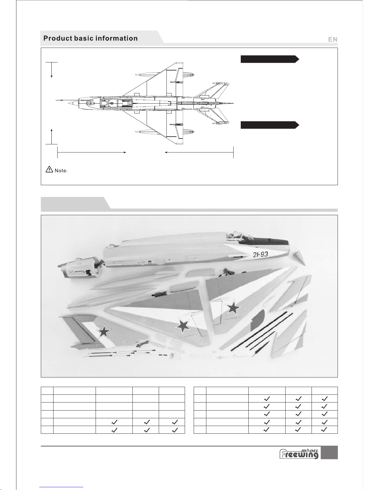
1605 mm(63.2 in.)
755m m(29.73 i n.)
比例 1.000
1730mm
(68.1" )
800mm( 31 .5")
2
Wingl oadin g:123 g/dm
Motor:3 530-1 800 KV outr unner m oto r
Fan:80m m 12- Bl ade f ans
ESC:100 A UBEC 5A
Servo s:9g Digi tal M G
Wei ght:218 0g
Thrus t:300 0g
(8pcs )
(W/O ba ttery )
MI G- 21MF F IS HB ED
It em No .:F J210
1
2
3
4
5
6
7
8
9
10
Standard Version
2
Wingloa di ng:125g /d m
Motor:3 65 8-1820K V in runner mo to r
Fan:80m m 12 -Blade fa ns
ESC:100 A UB EC 5A
Servos: 9g D ig ital MG
Weigh t:2215g
Thrust: 32 00g
(8pcs)
(W/O ba ttery )
Upgrade Version
Package list
No.
Spare part name
PNP
ARF Plu s
ARF
No.
Spare part name
Nose\Re ar fuselag e
Mainwin g
Horizon tal tail
Verti cal ta il
Oil-tan k&py lons
Carbo n fiber
Pilot t ube/A nte nna
Ventra l Fins
Pushr od/Sc rew s
Manua l/Dec als
No el ectro nic
equ ipmen t
Pre -inst alled a ll
ele ctron ic part s
Pre -inst alled
ser vo
No el ectro nic
equ ipmen t
Pre -inst alled a ll
ele ctron ic part s
Pre -inst alled
ser vo
No el ectro nic
equ ipmen t
Pre -inst alled a ll
ele ctron ic part s
Pre -inst alled
ser vo
The parameters stated here are derived from test results using our
accessories. If you use other accessories, the test results will differ. We
c
annot provide technical support if you have a problem when using other accessories.
Different types of kits will come with certain specific parts. Refer to the list of parts for your type of kit in the chart below.

3
(Ø8 x400m m)
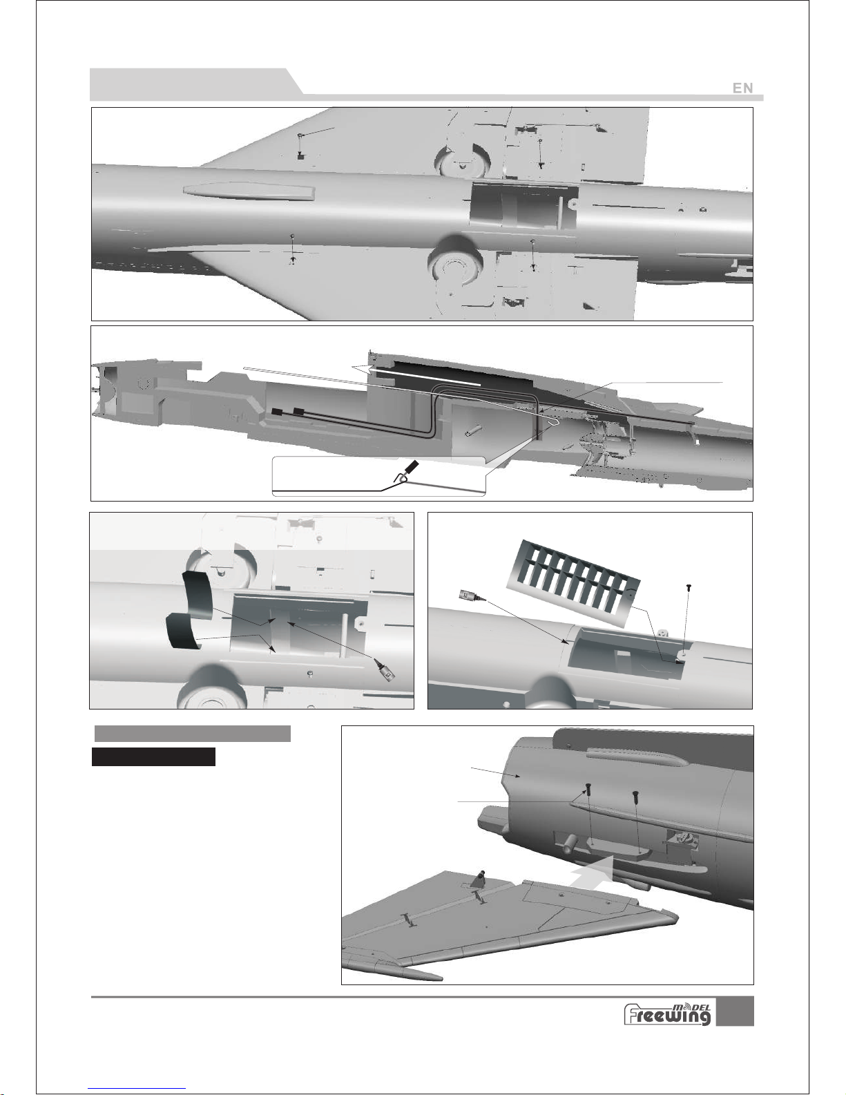
main wing t ro ugh port
Intake
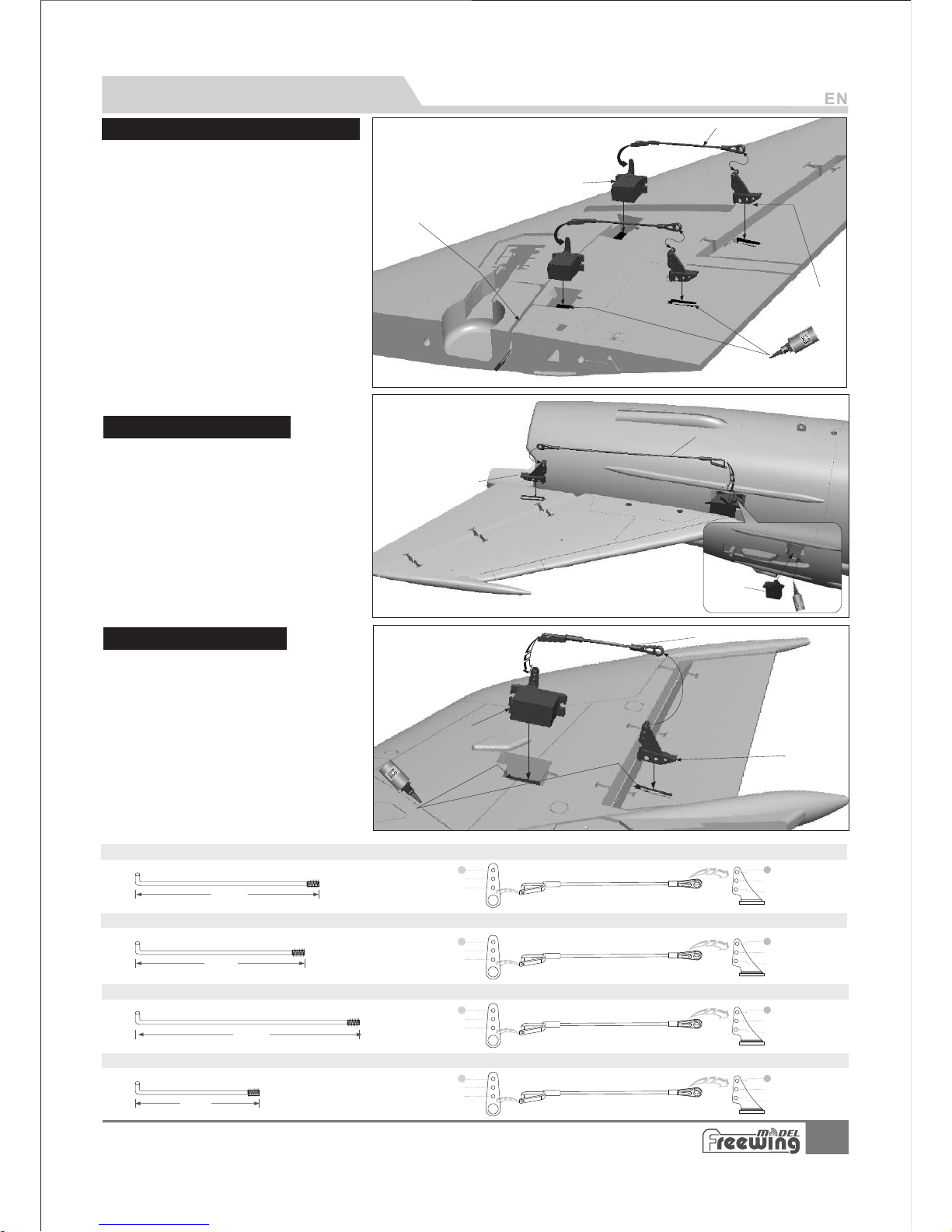
Elevator Servo wires
2.Use the steel wire to pull the elevator servo cables to the battery compartment.
MI G- 21MF F IS HB ED
It em No .:F J210
Carbo n tub e A
(Ø6 x345m m)
Carbo n tub e B
Battery t ra y
1.Use the provided glue to attach front\rear
fuselage parts.
Screws (KA3x10mm 4pcs)
PNP Assembly Instructions
Steel wire use instructions
Pre- Installation Preparation
1.Open the hatch and loosen the screws which hold the battery tray in
place. Remove the battery tray.
2. Re mo ve t he i ntake plate.
Fuselage Assembly
Main Wing Installation
Back of fus e
l
age
1.Insert the carbon tube A and B into fuselage.
2.insert the main wing servo cables into the fuselage wire trough
and into the ports.
Steel wire
B
a
t
t
e
r
y c
o
m
p
a
r
t
m
e
n
t
Our tests show that excessively long servo extension lines increase the risk of poor connections that can lead to servo
brown outs or failure, causing accidents during flight. Instead, this kit contains a steel wire that can be used to pull the
main wing/elevator and rudder servo wires through the airplane to the battery compartment, eliminating the need for
extension wires.
There is EPO glue provided with the kit. Apply the glue to the fuselage parts and allow it to
sit for 2 minutes. Press the two pieces together several times and allow the glue to get 'stringy'.
Push the two parts together a final time and allow the glue to set.
4
Main wing s er vos wire
Landing g ea r wire
Screws (PM3x6 4pcs)
E
SC
A-Tail fuselage
B-
Screws (KA2.6x8 4pcs)
A
B
MI G- 21MF F IS HB ED
It em No .:F J210
Screw
(FA 3x8 mm)
PNP Assembly Instructions
6.Use glue and screw to secure the intake plate.
3.Use 4 screws to secure the main wing.
4.Use the steel wire to pull the left and right wing connection wires to the battery compartment.
5.Use pla st ic cover to c lose the ma in w ing conne ct ion cable
trough on t he i nner wall .
Battery c o
mpar
tme
nt
1. Place the elevator onto the tail of the fuselage
2. Use 2 screws to
secure the elevator
3. Repeat the above steps to install the other
elevator.
Elevator and Rudder Installation
Elevator Installation

I
5
D
C
A
B
H
F
A B CDE F GHI J K -
J
K
D
B
C
A
G
E
MI G- 21MF F IS HB ED
It em No .:F J210
(Ø
5x180 mm
)
Carbon tube
PNP Assembly Instructions
1.Use the steel wire to pull the rudder servo cable through to the
battery compartment.
2. Use 4 screws to secure the rudder.
A. Vertical tail
B. Tail
fuselage
C. Servo wire
D. Screws (FA3x8 4pcs)
Rudder Installation
Nose cone, pitot tube, wing fence and drop tank pylons Installation
Nose cone
Antenna
Pitot tub e pa rt 1
Carbon tu be
Pitot tub e pa rt 2
Plastic p ar t 1
Plastic p ar t 2
Wing fenc e
Fin
Pylon
Drop tank
(left /ri gh t)
Note:
1.
2.
After finishing the above steps, depending on the model of the control board, insert all servo cables to the control board.
Finally use 4 screws to secure the battery tray . (all servo cables run under the battery tray)
6
A
B
C
B
C
A
B
A
C
Ser
v
os
wire
D
Pus hrod di amete r Ø1. 5m m
90m m
(3- 1/2")
Pus hrod di amete r Ø1. 5m m
80m m
(3- 1/8")
1
2
3
2
3
1
1
2
3
2
3
1
1
2
3
2
3
1
1
2
3
2
3
1
Pus hrod di amete r Ø1. 5m m
158 mm
(6- 1/4")
Pus hrod di amete r Ø1. 5m m
58m m
(2- 5/16" )
MI G- 21MF F IS HB ED
It em No .:F J210
Servo Installation Instructions
1.
Use a servo tester or radio to center the
servo.
2.
Use glue to install the servos and control
horns to the main wing.
3.Feed the servo cables through the trough,
after all the cables are in place, apply the
decal over the trough.
4.
Feed one end of the pushrod into the
aileron servo arm and adjust its length.
Snap the clevis to the aileron control
horn's ball link.
5.
Feed one end of the pushrod into the
flap servo arm and adjust its length.
Snap the clevis to the flap control
horn's ball link.
6.
Repeat the above four steps for the
other aileron and flap servo.
Flap and Aileron Servo Installation
A - 9g servo
B - Main wing pushr od
C - Aileron horn
D - Main wing servo t ro ug h
Elevator Servo Installation
1.
2.
Use a servo tester or radio to center
the servo arm.
Use glue to intall the servos on the
elevator servo mounts.
3.Feed one end of the pushrod into the
servo arm and adjust its length. Snap
the clevis to the elevator control horn's
ball link.
4.Repeat the above steps to install
the servo on the opposite side.
A - 9g servo
B - Elevator horn
C - Elevator push ro d
1. Use a servo tester or radio to center
the servo arm.
2. Use glue to install the servo to the
Horizontal Stabilizer and the control horn
to the rudder.
3. Feed the servo cables into the trough.
4. Feed one end of the pushrod into the
servo arm and adjust its length. Snap
the clevis to the rudder control horn's ball
link.
A - 9g servo
B - Rudder ho rn
C - Rudder pu sh rod
Rudder Servo Installation
Aileron p us hrod size
Flap push ro d size
Aileron p us hrod moun ting hole
Flap push ro d mountin g hole
Rudder pu sh rod size
Rudder pu sh rod mount ing hole
Elevato r pu shrod siz e
Elevato r pu shrod mou nting hol e
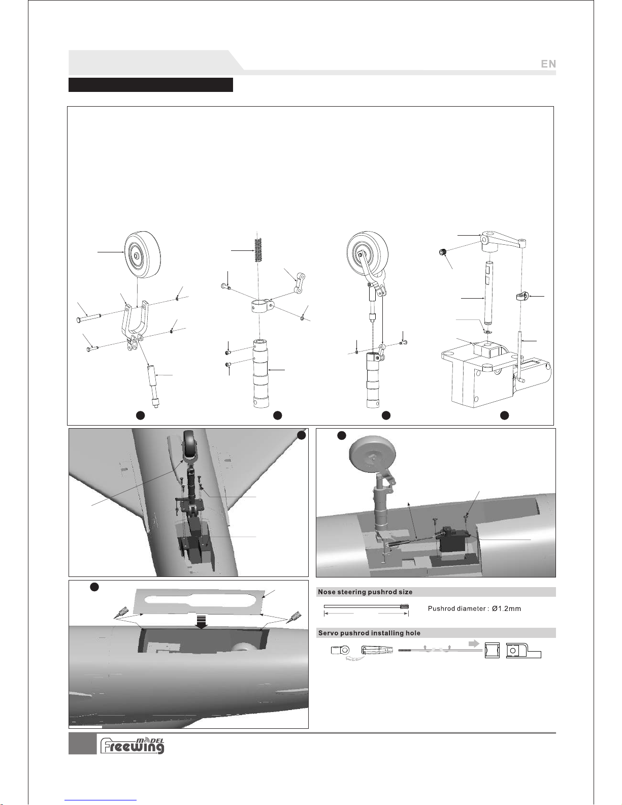
A B CDE F GHI J -
Nose wheel
Nose gear axle
U-shape slant supporting rod
E-clip
Pin
E-Clip
(Ø2.0pcs)
(Ø3.5X9.2mm 2pcs)
(Ø1.5mm 2pcs)
Nose gear shock absorber active rod
Spring
8-shape connecting arm
Screw (PM2x3 1pc)
Screw
Nose gear main supporting rod
Pin
Nose gear steering arm
Screw
Nose gear main rod
Nose gear steering control ring
Nose gear steering rod
E-clip
(PM2x4 1pc)
E-clip (Ø1.5mm)
(Ø3.5x9.2mm)
(M3x3mm)
(Ø2mm)
K L MN OP QR S T -
Nose landing gear set
Screws
Retract controller
(FA3x8 4pcs)
Nose landing gear mount
Nose steering pushrod
9g servo
Screws (PWA2x8mm 2pcs)
Nose landing gear cover
U-
V-
W-
XABACADAE-
( 2- 9/16 ")
65m m
AE
A
B
C
D
E
F
G
E1
F1
H
I
J
K
L
M
N
P
O
Q
R
S
T
U
Step
1 2 3 4
W
X
V
AB
AC
AD
5
6
7
7
MI G- 21MF F IS HB ED
It em No .:F J210
Landing Gear
Nose Landing Gear Assembly
Assemble and disassemble the nose landing gear according to the following photos.
Step Step Step
Step Step
Step
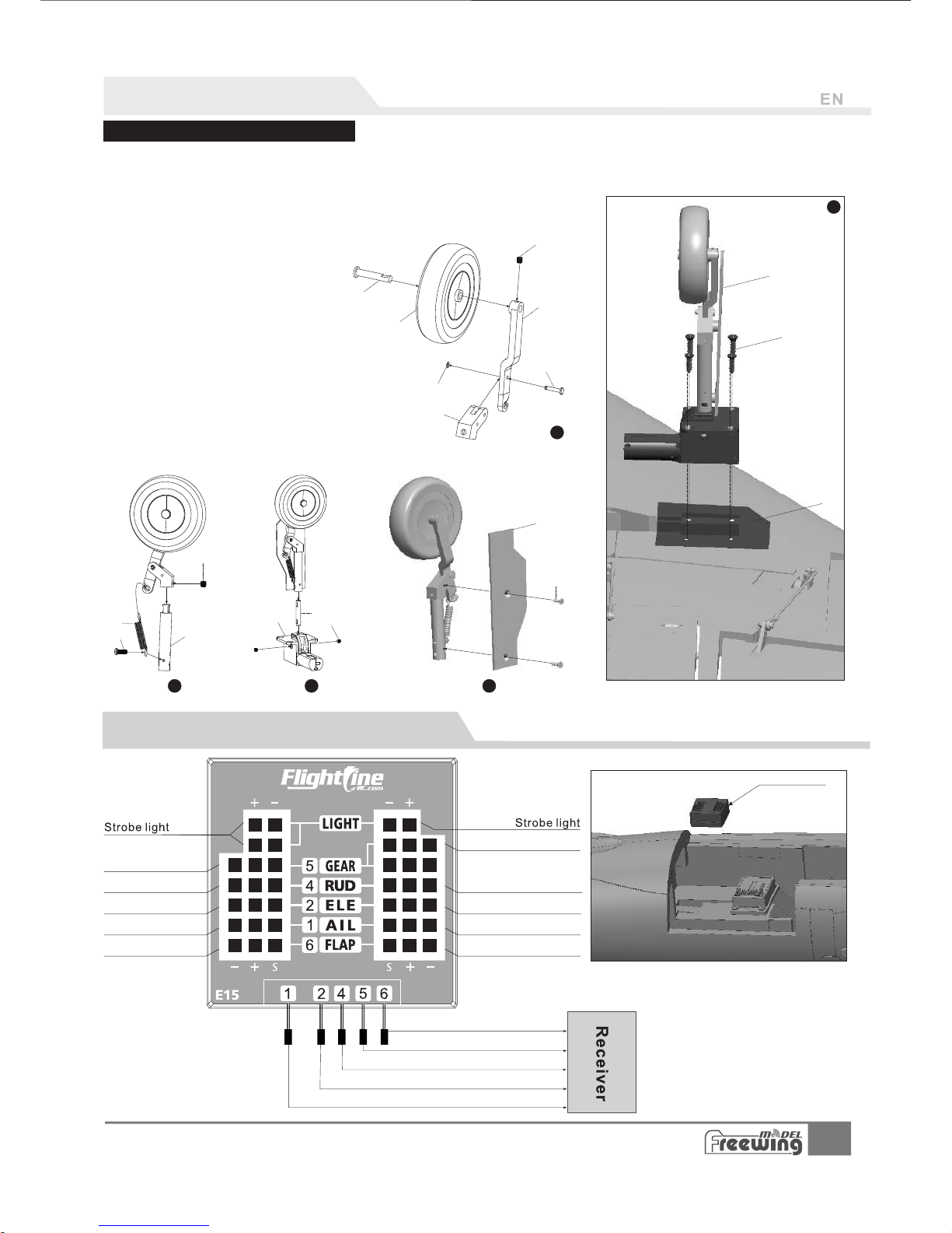
A B C D E F GH I J K L MN OR -
Main gear axle
Screw
Rear gear slant supporting rod
Pin
E clip
Main gear trunion A
Screw
Spring
Screw
Main wheel
(M3x3mm)
(Ø3.5X9.2mm 1pc)
(Ø1.5mm 1pc)
(M4x3mm)
(PM3x4 1pc)
Main gear main supporting rod
B
Main gear main rod
Grub screws (M4x4mm)
Retract controller
Nose gear door
Screws (PM2x5 2pcs)
A
B
C
D
E
F
G
ST U-
Main landing gear set
Screws (FA3x8 4pcs)
Main landing gear mount
S
T
U
1
H
I
J
K
2
M
L
N
3
O
R
4
5
8
MI G- 21MF F IS HB ED
It em No .:F J210
Landing Gear Installation
Rear Landing Gear Assembly
Assemble and disassemble the rear landing gear according to the following photo.
Step
Step
Step
Step
Step
When you use a gyro,
Elevator \ Aileron \ Rudder channels
from the Control Board connect directly
to the gyro outputs, then from the gyro
inputs to the receiver. All the other
channels will connect directly to the
receiver from the Control Board.
Refer to the model of the control board, insert all
the connection cables to the control board.
( Not including throttle, the throttle cable goes directly to
the receiver .)
Contr ol boar d
Landing G ea r
Flap
Landing gear
Rudder
Elevator
Aileron
(power to the receiver)
Landing G ea r
Rudder/Nose steering
Elevator
Aileron
Flap
Rudder/Nose steering
Elevator
Aileron
Flap
M
Control Board Introduction and Use
 Loading...