

Page 1
www. sz- fr eewing. com
EN 1~15
中
16~30
R
1/10 Scale Twin 80mm EDF JET
User Manual
Wingspan:1700mm(66.9")
Weight:4250g (w/o Battery)
Length:1551mm(61.1")
Page 2
1
A-10 Thunderbolt II
Item No .: FJ 311
Thank you for purchasing our Freewing 80mm EDF j et A-10 thund erbolt II. The origina l A-10
thunderbolt II is a single-seat twin-engine attack plane, produced by the Fairchild. It is no w the
only continuous service jet in US Air Force which provided the implemen t intensive support for
the ground forces.
Freewing 80mm EDF jet A-10 thunderb olt II, length is 1551mm (61.1”), wingspan is 1700mm
(66.9”). Main wing and horizontal tail take the hollow frame design, reduce the weight
effectively, and significantly increase m ain wing’s strength . Thre e piece control b oards install ed
on the fu selage and main wing on both side. Through the ribbon w ire connection, reduced its
install time, and increased the connection reliability. The model use screws to fix, you can
assemble/disassemble it in sh ort time and convenience for carry and sh ip.
A-10 thunderbolt II mode l plane used the grey color scheme and posted most decals in
factory. In package, we put three different set nose fuselage decals, please refer to the decal
instructions, choose one set to stick on the nose fuselag e.
It used the newest 9-blade dual 80mm EDF with 3530-1900KV brush less out-run ner motor
and 100A ESC. In fight, one side continues current is about 85A. Use 2 set 5000mAh lipo
battery, its flight time is about 3.5 ~ 4 minutes, the max flight speed is about 180KPH / 110MPH.
Whether it is high speed flight or low speed flight, it h as excellent flight stability, easy to c ontrol.
Excellent short takeoff and landing performance, with the new 70mm nos e wheel/85mm rear
wheel, you can fly in kinds of flight ground.
Wish you have a pleasant flight!
Catalog
Introduction
Product basic information
Package list
PNP In sta ll In sturct ions
Tra cti on st eel w ire u se in str uct ion
Install fuselage
Install Horizontal stabilizer / Vertical stabilizer
Install Engine compartment
Install Main wing
Install Miss iles
Install scale accessories
Pushrod instructions
1
2
2
3
3
3
4
4
5
6
6
Control board connection diagram
Battery size
Center of gravity
Control direction test
Dual Rates and Flight Attention
Accessories Description
Servos Introductions
Parameter of motor
Install the Motor and 90mm EDF power syste m instru cti on
Install pushrod
Install nose landing gear
Install rear landing gear
7
8
8
9
10
11
11
12
13
14
15
Page 3
Package list
2
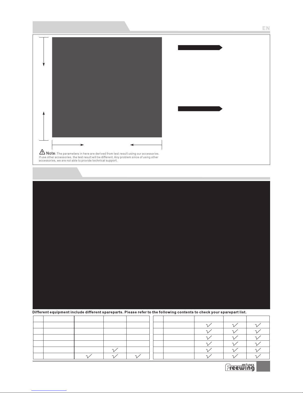
Product basic information
1700mm( 66.9")
1551mm( 61.1")
Material: EPO
Aileron: Yes
Flap: Yes
Elevator: Yes
Rudder: Yes
Landing gear: Retract landing gear
Cabin door: nose gear electric cabin door
Scale LED lights
Scale Pilot figure
2
Wing loading: 124g/dm
Motor: 3530-1900KV
brushless outrunner motor
Ducted fan: 80mm 9-blade fan
ESC: 100A brushless UBEC 8A(2pcs)
Servo: 17g Digital MG servo (9pcs)
30g Digital MG servo (2pcs)
9g Digital MG servo (1pcs)
Weig ht: 4 250 g(w ith out battery)
Thrust: 6600kg
Standard version
Other features
A-10 Thunderbolt II
Item No .: FJ 311
1
2
3
4
5
6
PNP
ARF Pl us
Airf rame
PNP
ARF Pl us
Airf rame
7
8
9
10
11
12
No. Name
No.
Fuse lage
Main w ing
Hori zonta l tail
Verti cal tai l
Carb on tube
Engine compartment
Pre -inst alled a ll
ele ctron ic part s
Pre -inst alled a ll
ele ctron ic part s
Pre -inst alled a ll
ele ctron ic part s
Pre -inst alled a ll
ele ctron ic part s
Pre -inst alled a ll
ele ctron ic part s
Pre -inst alled
ser vo
Pre -inst alled
ser vo
Pre -inst alled
ser vo
Pre -inst alled
ser vo
No el ectro nic
equ ipmen t
No el ectro nic
equ ipmen t
No el ectro nic
equ ipmen t
No el ectro nic
equ ipmen t
No el ectro nic
equ ipmen t
Link age Set
Scale ac ce ss or ie s
Stab ilize r wing
Manual & D ec al s
Glue & Non-slip mat
Scre w
Name
Page 4
3
PNP lnstall instructions
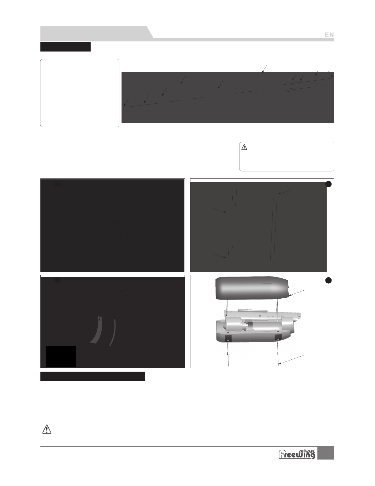
Use glue to install the front/rear fuselage.
AB-
Carb on tu be (Ø6x20 0m mm m)
Carbon square tube (8. 5x 8. 5x 80 0m m)
A
B
Step
4
Step
3
Batter y compartment
Elevator/rudder servo cable
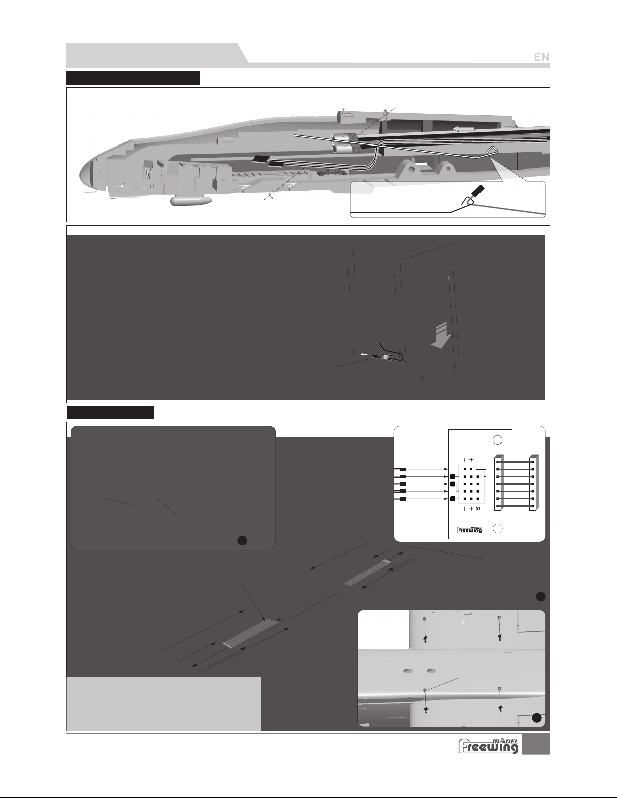
Tra cti on st eel w ire
Step
1
A
B
C
D
As the photo shown:
1.Install the vertical stabilizer on the horizontal stabilizer and use
2pcs screws to fix the left/r igh t ver tic al st abi liz er.。
2.When install the vertical stabilizer, pull out the rudder servo
cable through the inside trough。
3.Use the traction metal wire to pull the elevator/rudder servo cable
to the battery compartment.
4.Install the horizontal stabilizer on
the rear of fuselage and use 4pcs
screws to fix it.
A- Screw (PA 3x 8 4pc s)
B- Vertical tail
C- Hor izont al tail
D- Servos wire
E- Screw (PA 3x 8 4pc s)
E
Step
2
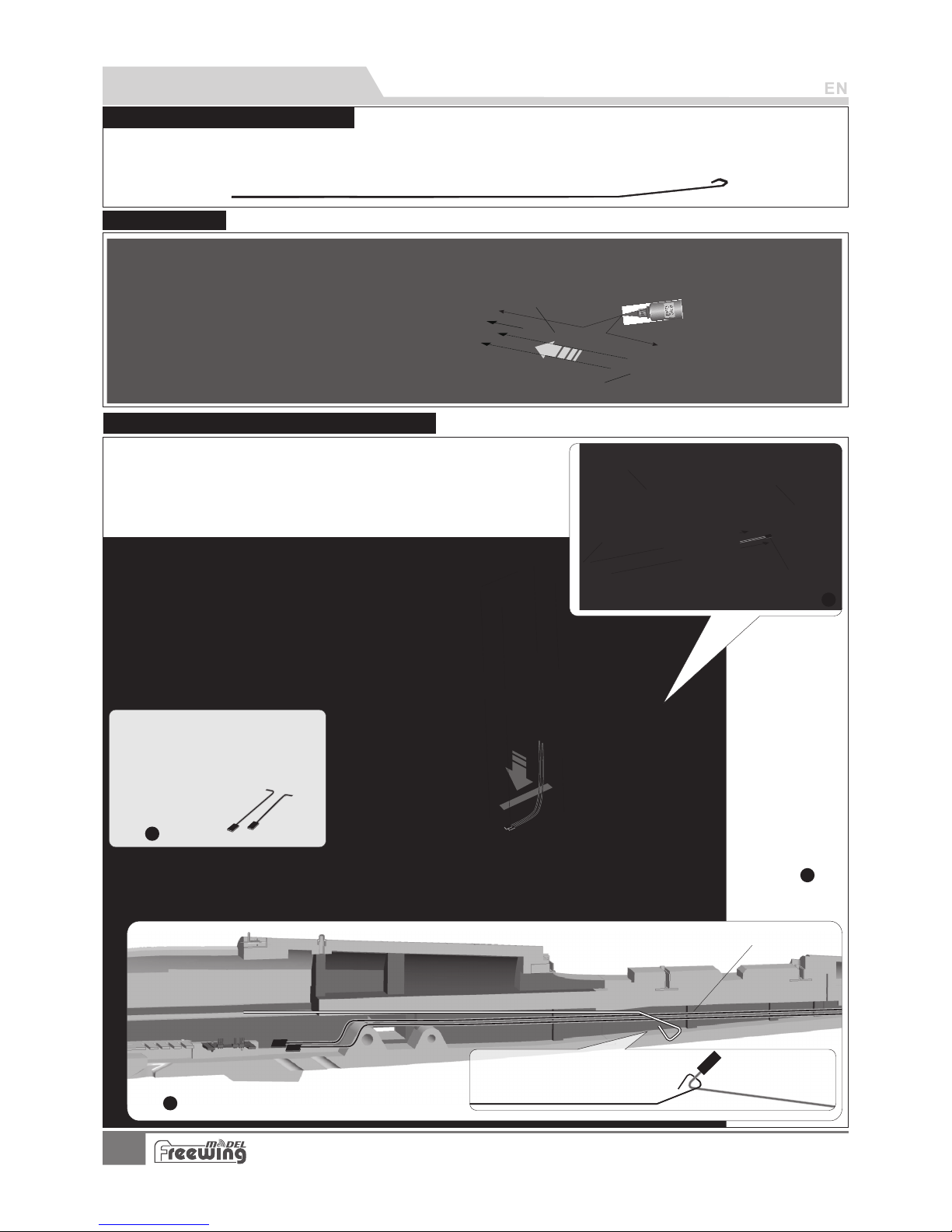
Traction steel wire use inst ruc tio n
Through in ves tig ati on, excessive ser vo extension l ine w ill in cre ase t he risk of poor con tac t joints, a nd lead to the
servo outages c aus ed fl igh t acci den ts. Becau se of A-10 larg e and fl at t rou gh i nte rio r space, we don' t use t he
servo extension wire in this jet. As the below photo shown, package includes a traction steel wire, we can use it to
pull the main wing/elevator/rudder servo cables to the battery compartmen t.
Install fuselage
A-10 Thunderbolt II
Item No .: FJ 311
Install Horizon tal s tab ili zer / Ve rti cal s tab ili zer
Page 5
Install Engine co mpa rtm ent
Step
2
4
EC5
1.Use the traction metal wire to pull ESC cable and throttle cable to the battery compartme nt.
2.Install the engine compartment to the rear of fuselage;
3.Use 6pcs screws to fix。
Screw ( 6pcs )PA3x 12
Step
1
A I L
FLAP
GEAR
LIGHT
1
6
5
Air leron
Fla p(Two)
Lan ding ge ar
Win g tip lig hts
Fla p(One )
Mai
n w
ing trough p or t
Carbon tube A
(Ø12 x570m m)
Carbon tube B
(Ø8x65 0mm)
Step
3
Ribbon wire
Control board
1.Insert the carbon tube A,B into the fuselage.
2.Insert the connection cable to the control
board, then install the left/right mai n wing
on the fuselage.
3.Use 4pcs screws to fix the main wing.
Screw
(PWM 4x8 4pc s)
ESC wire
Back o f fusel ag e
Batter y compartment
Tra cti on st e
el wire
Throttle wire
Throttle wire
ESC wire
PNP lnstall instructions
InstallMainwing
A-10 Thunderbolt II
Item No .: FJ 311
Page 6
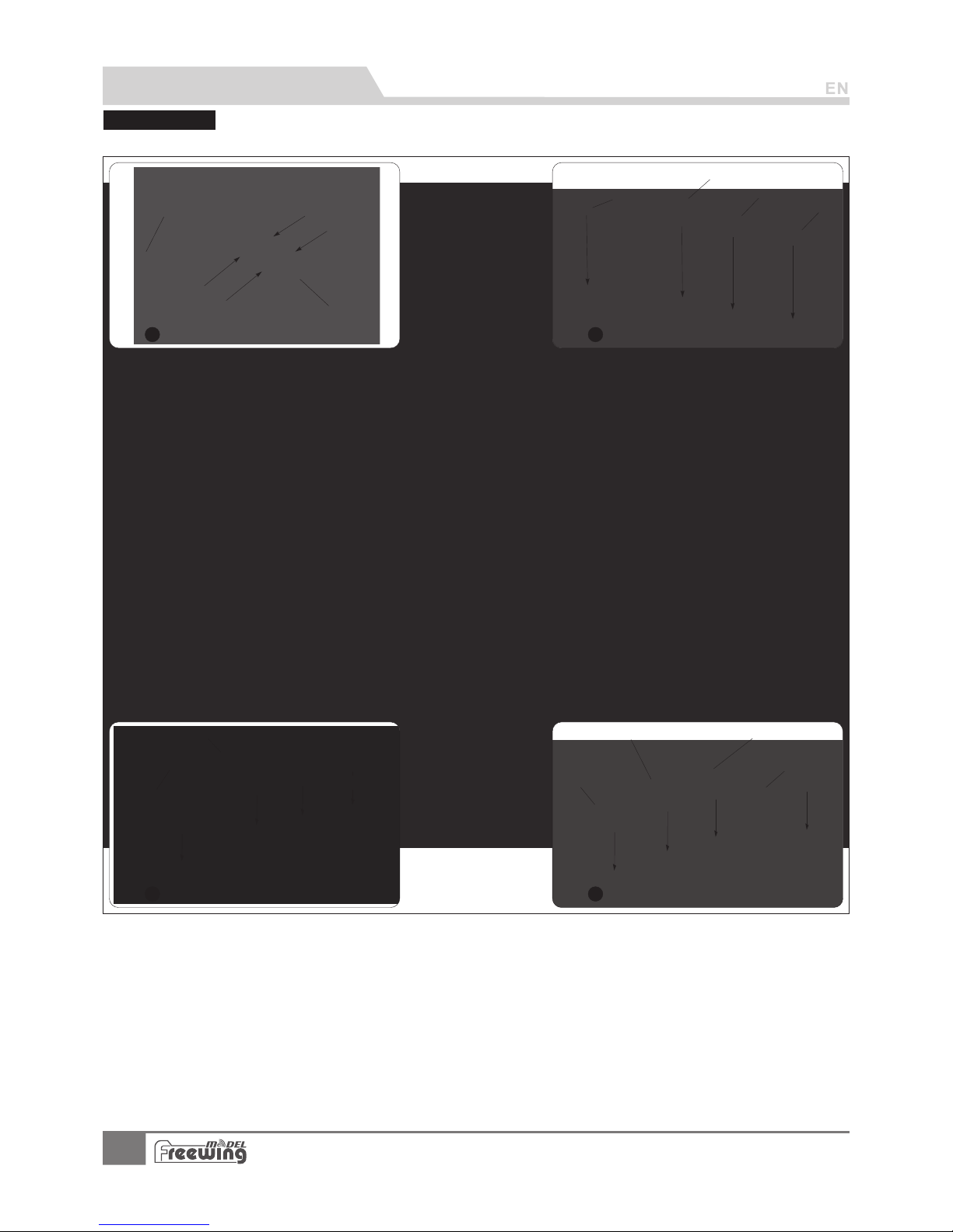
Install Miss il es
Step
1
Step
2
Step
3
Step
4
AIM- 9 pylon s
AIM- 9 Missi le s
AGM- 65 Miss il es
Mk-84
Mk-84
AGM- 65 Miss il es
LAU- 131
AN/A LQ-13 1
Please according the pictures as below to install the weapons
PNP lnstall instructions
5
A-10 Thunderbolt II
Item No .: FJ 311
pylo ns 1
pylo ns 2
pylo ns 3
pylo ns 4
Page 7
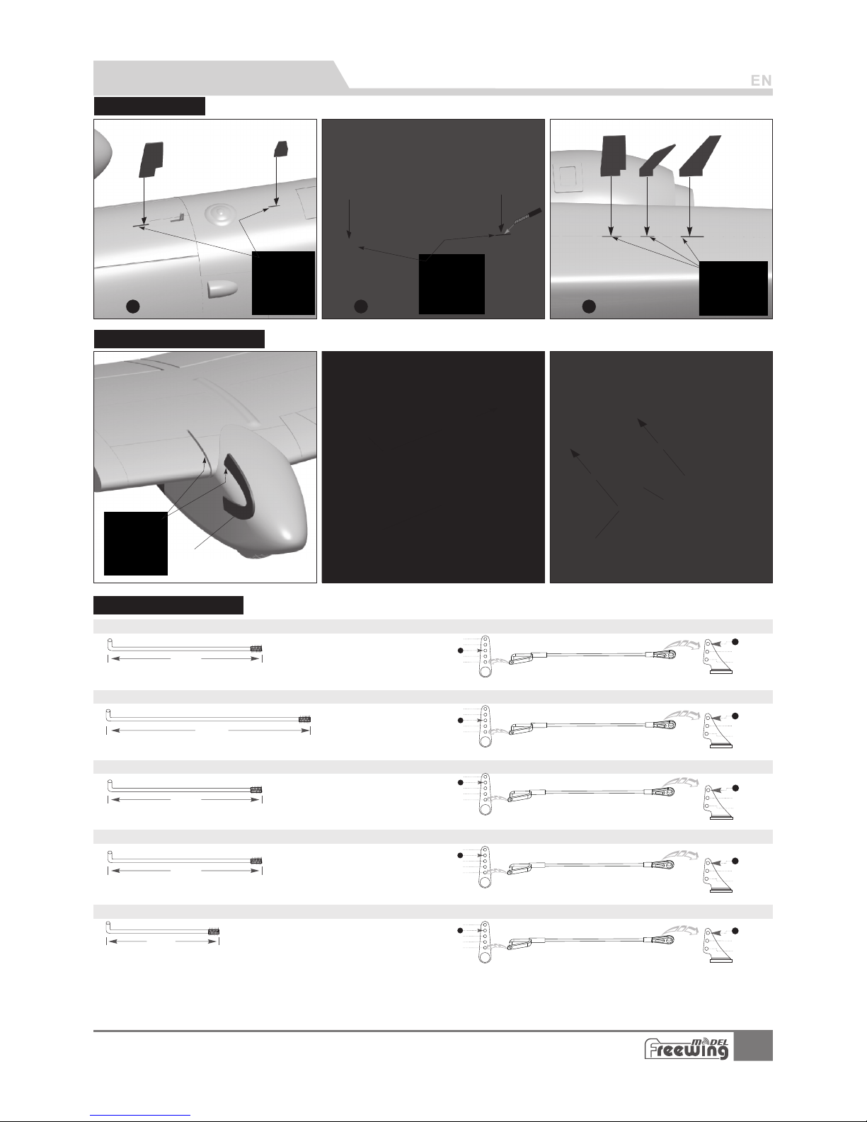
Step
1
Step
2
Step
3
Screw
(PM3 x6 1p cs)
Radar
Screw
(PA3x 8 2pcs)
Wing fence
34mm
63m m
(2- 1/2")
2
3
1
4
5
1
2
3
48m m
(1- 7/8")
2
1
4
5
3
1
2
3
76m m
(3" )
63m m
(2- 1/2")
2
1
4
5
3
1
2
3
63m m
(2- 1/2")
PNP lnstall instructions
Antennalnstall
Pushrod instructio ns
Flap p us hro d si ze(Ou t Side) Flap p us hro d mo untin g hole( Ou t Side)
Flap p us hro d si ze(In S ide) Flap p us hro d mo untin g hole( In S ide)
Aile ron pus hr od size
Aile ron pus hr od moun ting ho le
Rudd er p ush ro d size
2
3
1
4
5
1
2
3
Rudd er p ush ro d mount ing hol e
Elev ator pu sh rod siz e
Elev ator pu sh rod mou nting h ol e
Pus hrod di amete r Ø1. 5 mm
Pus hrod di amete r Ø1. 5m m
Pus hrod di amete r Ø1. 5 mm
Pus hrod di amete r Ø1. 5 mm
Pus hrod di amete r Ø1. 5m m
2
3
1
4
5
1
2
3
Install Radar, Win g-k nif e
6
A-10 Thunderbolt II
Item No .: FJ 311
Stabilizer wing
Page 8
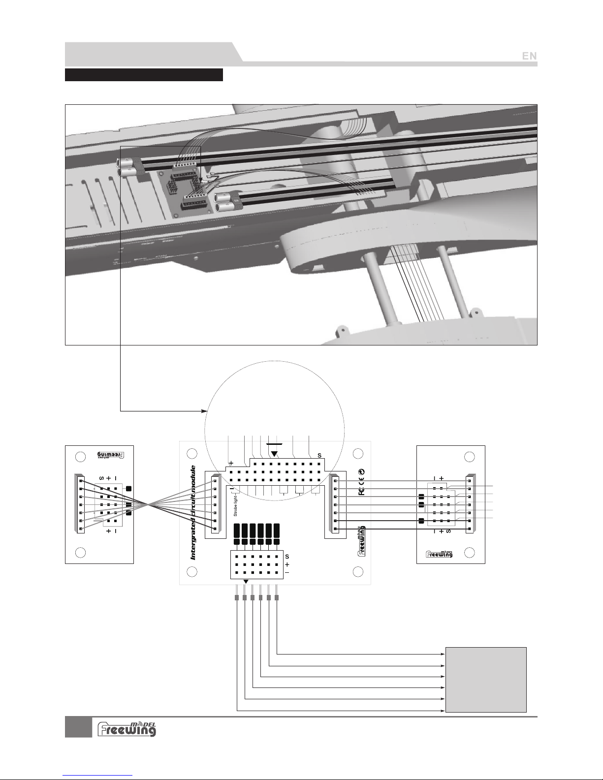
PNP lnstall instructions
Ser vo lnpu t
Rec eiver
A-10 Thu nde rbolt I I
6
5
4
3
1
2
E L E
T HR
RU D
GEAR
Nose Steering
GEARDOOR
Landing lights
FLAP
GEAR
RUD
E LE
A I L
T HR
1
6
5
A I L
FLAP
GEAR
LIGHT
Main wi ng c on tr ol b oa rd (R ig ht)
Main wing control board(Left )
1
6
5
A I L
FLAP
GEAR
LIGHT
Landing lights
Landing gear door
Landing gear
Nose steering
Rudder
Throttle
Elevator
EC5
A-10model plane used the ribbon wire, in order to use more convenient. Please refer to the following photo, connect
the electronic equipment.
Control board con nec tio n dia gra m
Airleron
Flap(Two)
Landi ng g ea r
Win g ti p li gh ts
Flap(One)
Strobe light
Conn ect the a il ero n ch ann el i n the rec eiver
Conn ect the e le vat or c hanne l in the re ceive r
Conn ect the t hr ott le c hanne l in the re ceive r
Conn ect the r ud der c ha nnel in t he rece iver
Conn ect the l an din g ge ar chan nel in th e recei ver
Conn ect the fl ap c han ne l in the re ceive r
RECEIVER
7
A-10 Thunderbolt II
Item No .: FJ 311
Page 9
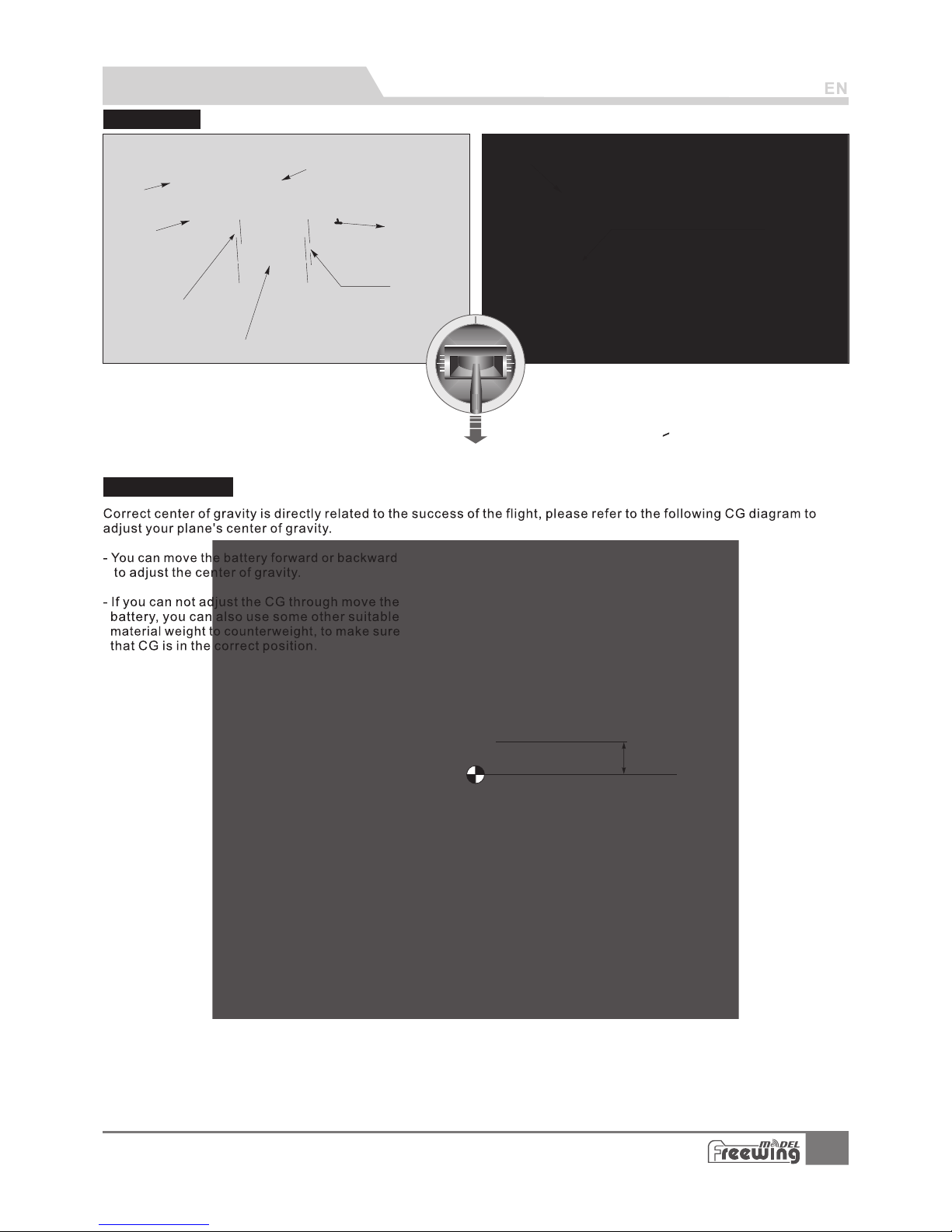
Battery size
Before connect the battery and receiver, please
switch on the transmitter power and make sure
the throttle stick is in the lowest positi on.
Batter y cabin size:
L=360 W=90 H=90(mm)
BatteryA
Battery B
Velcro A
Velcro B
Battery tr ay
Screw
(PA3x 8 8pcs)
P
ull t h
e sti cker ba ck
and o pen the c ockpi t.
Battery in st al l on t he f ro nt o fBattery in st al l on t he f ro nt o f
fusela ge , an d us e ma gi c ta pe t o fi x.fusela ge , an d us e ma gi c ta pe t o fi x.
Battery in st al l on t he f ro nt o f
fusela ge , an d us e ma gi c ta pe t o fi x.
Cockpi t
78mm
(3-1/16")
PNP lnstall instructions
The battery capacity and discharge rate we advise
is in the following:
6S 22.2V 4000mAh ~ 6S 22.2V 5200mAh (2pcs)
>
Discharge rate of C 30C
Center of gravity
8
A-10 Thunderbolt II
Item No .: FJ 311
Page 10
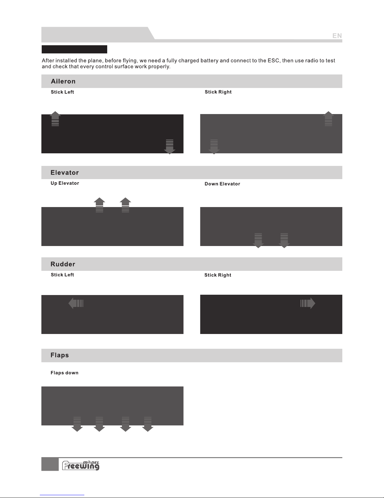
Control direction te st
PNP lnstall instructions
9
A-10 Thunderbolt II
Item No .: FJ 311
Page 11
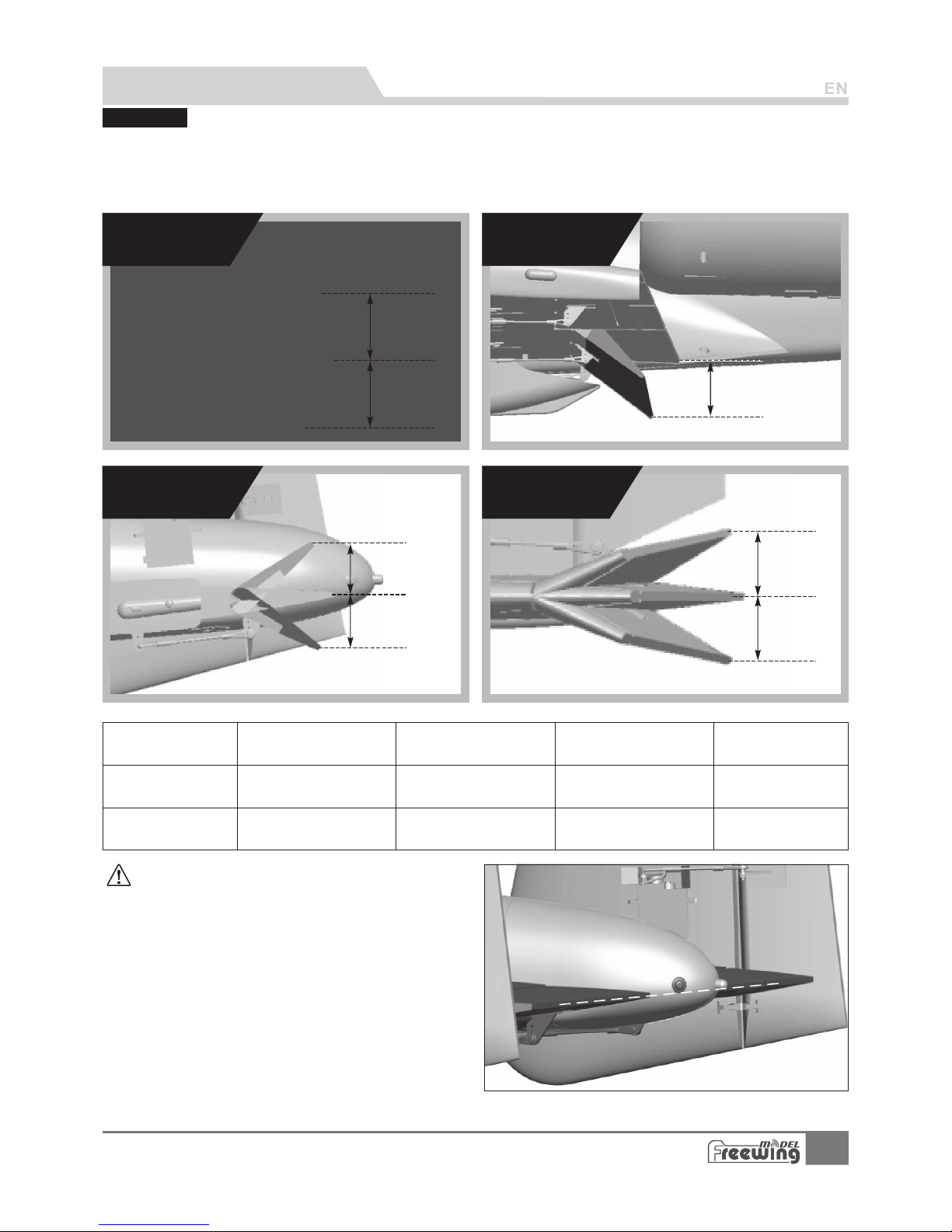
Ac cording to our test ing experience, use the following parameters to set aileron/elevator
rate, it will be useful for flight. In low rat e, it will oper ate more stab le. In high rate, it will operate more
sensit ive. We advi se to use high rate in you r first flight, then according to you r habit to cho ose
low/hi gh rate.
Low Rate
High Rate
Aileron
H1/H 2 30mm/ 30 mm
D/R Ra te: 70%
H1/H 2 40mm/ 40 mm
D/R Ra te: 100 %
H1/H 2 30mm/ 30 mm
D/R Ra te: 85%
H1/H 2 34mm/ 34 mm
D/R Ra te: 100 %
H1/H 2 20mm/ 20 mm
D/R Ra te: 85%
H1/H 2 26mm/ 26 mm
D/R Ra te: 100 %
H1 32m m
H1 50m m
H1
H2
H1
H1
H2
H1
H2
PNP lnstall instructions
Aileron
Flaps
Elevator Rudder
Elevator Rudder
Flaps
Dual rate s
Fligh t At tent ion:
1.Correct e leva tor ce nter position
After insta ll, w e nee d to adjust the el eva tor, c orrect
elevator c ent er po sition, plea se re fer t o the right phot o.
After adjus t, el eva tor looks a litt le up , it ha s a little up
elevator.
2.Fla p-el evat or mix parameter
When open th e fla p, th e jet will chang e the f lig ht
directio n, it w ill f ly up the sky. In or der t o operate bett er,
we advise yo u set t he “Flap-elevat or mi x” in radio. In
this case, w hen y ou op en the flap, the j et do n’t c hange
its flight .
Setting ra nge i s as fo llowing:
Open flap 50 mm, p re- set 3mm elevat or do wn
Open flap 32 mm, p re- set 2mm elevat or do wn
At last, acc ord ing t o your operati ng, y ou ca n increase or re duc e its rate.
10
A-10 Thunderbolt II
Item No .: FJ 311
Page 12
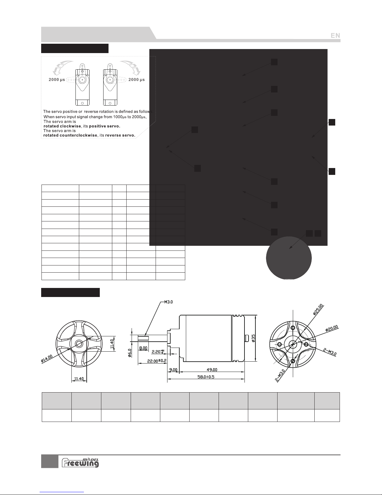
Servos Introduc tio ns
Lan ding ge ar door
No.
Pos./R ev.
Cable le ng th
1
2
3
4
5
6
7
8
9
10
11
12
Positi ve
Positi ve
Positi ve
Positi ve
Positi ve
Positi ve
Positi ve
Positi ve
Positi ve
Revers e
Positi ve
Positi ve
600m m
600m m
600m m
600m m
120m m
120m m
360m m
360m m
950m m
950m m
1200 mm
1200 mm
Model
1
2
3
5
7
4
6
8
9
10
Unit: (mm)
3530 -1 90 0K V
11 12
O/R BL 35 30
Item N o.
Use mo tor
moto r(KV) Thru st (kg )
Curr ent(A )
Use voltage
(V)
Use ES C
(A)
EDF Weight
(g)
Max po we r
(W)
Efficiency
(g/w)
1900
22.2 (6 S)
3300 90 100 278 2000 1.65
Accessories Description
If you n eed t o purch ase o ther br and s ervo, p lea se
refe r to th e follo win g list to c hoo se corr ect s ize ser vo.
Positi on
Ailero n(L)
Ailero n(R)
Flap(L )
Flap(R )
Flap(L )
Flap(R )
Elevator (L )
Elevator (R )
Rudder(L )
Rudder(R )
Nos e gear
ste ering s ervo
Parameter of motor
11
A-10 Thunderbolt II
Item No .: FJ 311
MO035303
E723 10
17g Digi ta l MG
9g Digital M G
30g Digi ta l MG
30g Digi ta l MG
17g Digi ta l MG
17g Digi ta l MG
17g Digi ta l MG
17g Digi ta l MG
17g Digi ta l MG
17g Digi ta l MG
17g Digi ta l MG
17g Digi ta l MG
Page 13
Install the Motor
A
B
C
D
E
F
G
H
I
J
A
B
C
D
E
F
G
H
I
J
ABCDE-
ESC fixed mount
ESC
ESC fixed part
Screw ( PA3 x8 4p cs )
Power system fixed mount
F GHI J -
80mm EDF power system
Screw (PWA3x8 4 pcs)
Plastic cover
Engine compartment cover
Screw (PA3x8 4 pcs)
Accessories Description
Refer to the following d iag ram , ins tal l ESC a nd po wer s yst em:
Note: Wh en E SC and ba tt er y co nn ec te d,
pr ohi b i t to tou ch th em by ha nd to av o i d
accide nt al inj ur y.W he n t es t E DF,p le ase use
safety tes t st an d fo r te st in g, pr oh ib it to touch
by hand for te st in g.
Step
2
Step
3
Step
4
Step
1
Standard version
A B CDE -
F GHI J -
Scre w
Moto r spi nner
Cup he ad sc rews (M 3x 7 4p cs )
Was her
80mm d uct ed fan fr ame
for ou tru nner mo tor
3530 -19 00KV mo tor
80mm 9 -bl ade duc ted f an
Spin ner
Was her
Cup he ad sc rews (M 3x 12 1 pc s)
We hav e pro vid ed mo re po wer o pti ons f or th e A-10 , you c oul d cho ose a not her 9 0mm e ngi ne co mpa rtm ent s et,
and follow the above steps to install your new 90mm EDF power system. The assemble size of 90mm engine
compartment set, suit for all Freewing 90mm EDF power system an d 130 A ESC.
ESC cable specification
The cable length for motor output port: 10 0mm
The cable length for power port: 200mm
Note:The other brand power system and its ES C, ma ybe d on’ t sui t for t his e ngi ne co mpa rtm ent , ple ase
choose carefully.
90mm EDF power system instruction
12
A-10 Thunderbolt II
Item No .: FJ 311
Page 14
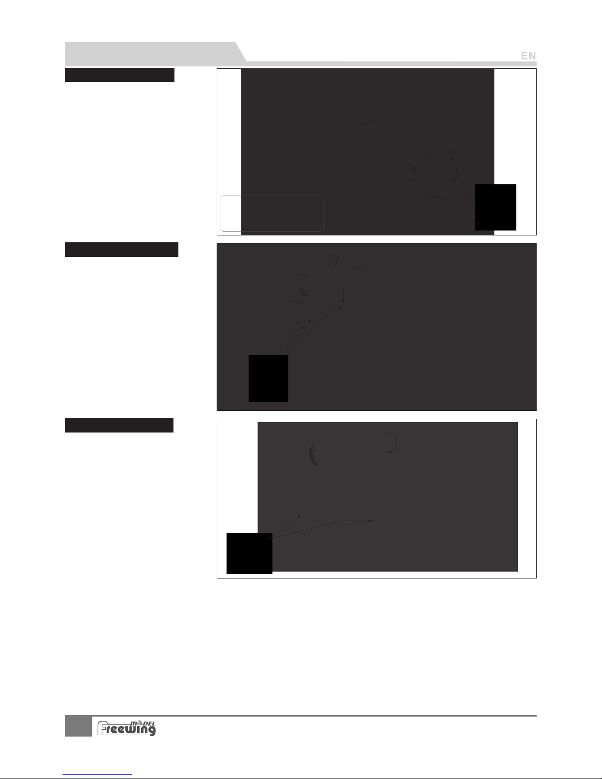
Install Ail ero n pus hro d
ABC-
Servo
Elevator pushrod
Elevator horn
A
B
C
ABCD-
Servo
Main wing pushrod
Aileron horn
Main wing servo trough
Accessories Description
Install Elevator pus hro d
Install Rudder pu shr od
1.Use servo tester or radio to
center the servo.
2.Use glue to install the servo
and aileron horn on the main
wing.
3.Buckle the servo cable to the
through, after installed all the
servos, stick on the decal.
4.One side pushrod insert to the
servo arm,adjust its length.
And insert the clevis to the
aileron horn.
5.Repeat the above four steps,
install the other side main wing
servo and flap servo.
1.Use servo tester or radio to
center the servo.
2.Use glue to install the servo
and aileron horn on the
elevator.
3.Buckle the servo cable to the
through, after installed all the
servos, stick on the decal.
4.One side pushrod insert to the
servo arm,adjust its length.
And insert the clevis to the
aileron horn.
5.Repeat the above four steps,
install the other side main wing
servo and flap servo.
1.Use servo tester or radio to
center the servo.
2.Use glue to install the servo
and aileron horn on the
Rudder.
3.Buckle the servo cable to the
through, after installed all the
servos, stick on the decal.
4.One side pushrod insert to the
servo arm,adjust its length.
And insert the clevis to the
aileron horn.
5.Repeat the above four steps,
install the other side main wing
servo and flap servo.
ABC-
Servo
Rudder pushrod
Rudder horn
Note:
: T he re i s a EPO glu e on
packa ge , Ple as e use it to glu e.
Glue should b e spre ad eve nl y
and wait fo r 90 seco nd s. Th en
insta ll o n, i ts b es t gl ue c on di ti on.
A
B
C
D
13
A-10 Thunderbolt II
Item No .: FJ 311
Page 15
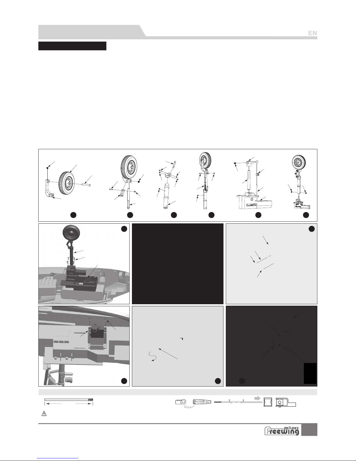
Install nose land ing g ear
Pus hrod di amete r Ø1.5m m
( 2-7 /8")
68m m
Step
1
Step
2
Step
3
Step
4
Step
5
Step
6
Step
7
Step
8
Step
9
A
B
C
D
F
E
G
H
I
J
K
L
M
M1
N
O
P
Q
S
T
U
V
W
X
Y
Z
Z1
Step
12
Step
11
Step
10
AB
AC
AD
AE
AF
AG
AH
AI
AJ
AK
AM
AN
AO
AP
AQ
AR
Please assemble、disassemble the rear land ing g ear a cco rdi ng to t he fo llo win g photo.
R
A B C D E F GH I J K L MN O-
Nose gear axle
Nose wheel ( Ø mm)70x2 0
JIMI Screw (M4 x3)
Nose g ear slant st rut
IMI Screw (M4x 3)
Pin (Ø 3.5 X9 .2mm)
H-St rut
C-Buckle (Ø1 .5mm)
Nose gear shock absorber active rod
8-shape connecting arm
Pin (Ø 3.5 X9 .2mm)
C-Buckle (Ø1 .5mm)
Screw (PM 2x3 2pc s)
Screw (PM 2x4 1pc s)
Nose gear strut
P-
Q-
RS-
T-
U-
V-
W-
X-
YZ-
ABACAD-
Pin (Ø 3.5 X9 .2mm)
(Ø1. 5mm)C-Buckle
Spring
Screw (PM 2x4 1pc s)
IMI Screw (M3x 3)
L-shape rotating arm
O-shape ring
Pushrod
Nose metal wire
Retract controller
IMI Screw (M4x 4)
Nose landing gear
Screw (PWA3 x12 4 pcs )
Nose landing gear mount
A E A F AGAH A I A J A K A L AMAN AOA P AQAR -
Screw (PA2 x8 1 pcs)
LED lights
LED light fixed arm
Screw (PM 2x3 1pc s)
Nose landing gear door type
Spring
Screw (PWA3x8 1 pcs)
(PWA2.3x 6 1pcs)Screw
Servo
Screw (PWA2x8 1 pcs)
Nose s teeri ng p ush ro d
Cabi n door se rv o
abin do or pus hro dC
N ose cabin door
AL
Nose s teeri ng p ush ro d size
Serv o pushr od i nst al ling ho le
Note :W hen i ns talli ng,pl ease ch eck the fl at p osi ti on of spa repar ts,wh en s cre w to fi x,the fl at posi tion mu st face t o th e screw h ole,
,
just l ike thi s, i t can fi x su ccess fully, the s parep ar ts do n t ro tate an d fall off.
Accessories Description
14
A-10 Thunderbolt II
Item No .: FJ 311
Page 16
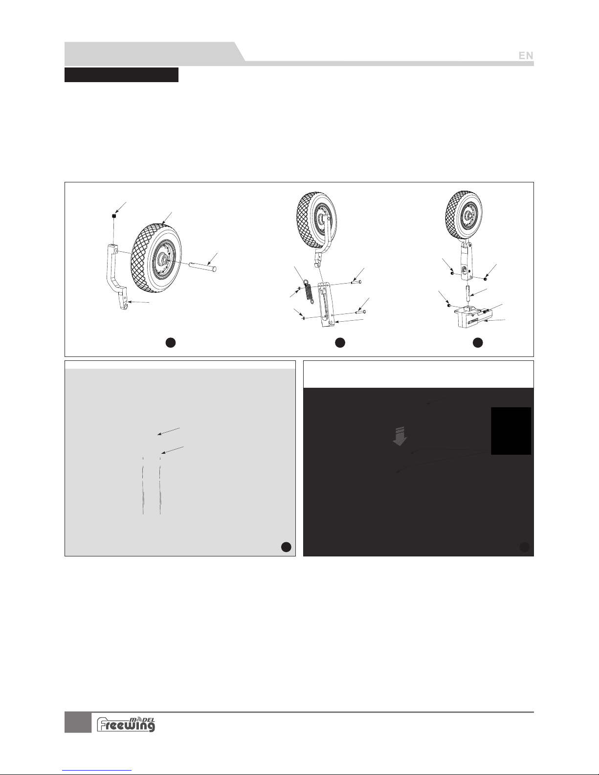
Install rear landing g ear
Please assemble、 dis ass emb le th e rea r lan ding gear according to the follow ing p hot o.
Step
1
Step
2
Step
3
A
C
B
D
E
E1
F
G
G1
H
I
I1
J
K
K1
L
M
N
O
Step
4
Step
5
AB CDE F GH-
Main gear axle
Main wheel ( Ø mm)85x2 6
JIMI Screw (M4 x3)
L-Sl ant str ut
Pin (Ø 3.5 X9 .2mm)
Spring
C-Buckle (Ø1 .5mm)
Main gear strut
I J K L -
MN O-
JIMI Screw (M4 x3)
Main gear main rod
JIMI Screw (M4 x3)
Electronic retract
Main landing gear
Screw (PWA3x1 2 4pcs)
Rear g ear pla st ic co ve r
Accessories Description
15
A-10 Thunderbolt II
Item No .: FJ 311
Page 17

Add.:FeiYi Building,face to Labor Bureau, Fumin Middle Road, Dalang Town,
Dongguan City,Guangdong Province, China
HK Freewing Model International Limited
东莞市飞 翼 电 子科技有限 公 司
香 港 飞 翼 模 型 国 际 有 限 公 司
地址: 广 东 省东 莞市大 朗镇 富 民中 路4 0 2-40 8号 飞翼 楼 四楼
Web: http://www.sz-freewing.com
Email:[email protected]
Tel: 86-769-82669669 Fax:86-769-82033233
Web: http://www.sz-freewing.com
Email:[email protected]
Tel: 86-769-82669669 Fax:86-769-82033233
Dongguan Freewing Electronic Technology Ltd
R
 Loading...