

www. sz- fr eewing. co m
EN 1~7
中
8~14
U S E R M A N UA L
1
Introduction
Basic Product Information
Package List
PNP Install Insturctions
Install Main Wing
Install Vertical Stabilizer
Install Antenna
Pushrod instructions
Battery Size
Center of Gravity
Control Direction Test
Dual Rates and Flight Attention
Accessories Description
Motor Specifications
Motor Overview
Accessories Introduction
Servos Introductions
Install nose landing gear
lnstall rear landing gear
Ite m No.:F J11 0
Catalog
1
2
2
3
3
3
3
4
4
5
5
6
6
6
7
7
2
1
2
3
4
PNP
ARF Pl us
Airf ra me
PNP Airf ra me
5
6
7
8
ARF Pl us
Stan dard ve rsion
2
Wing L oadin g: 50g/ dm
2
WingA rea:8 dm
Moto r: 2627 -4500 KV
Brus hless O utrun ner Mot or
Duct ed fan: 6 4mm 5-B lade Fa n
ESC: 3 0A Brush less
Serv o: 9g Pla stic Se rvo(2 pcs)
Top Spee d : 160KP H/100 MPH
Empt y We ight: 260g( witho ut b attery)
Benc h Test ed Thrust : 750g
Land ing gea r: fixed l andin g gear
(Op tiona l spare p art, ne ed to pur chase s epara tely.)
750m m(2 9.5")
495m m(1 9.5")
Ite m No.:F J11 0
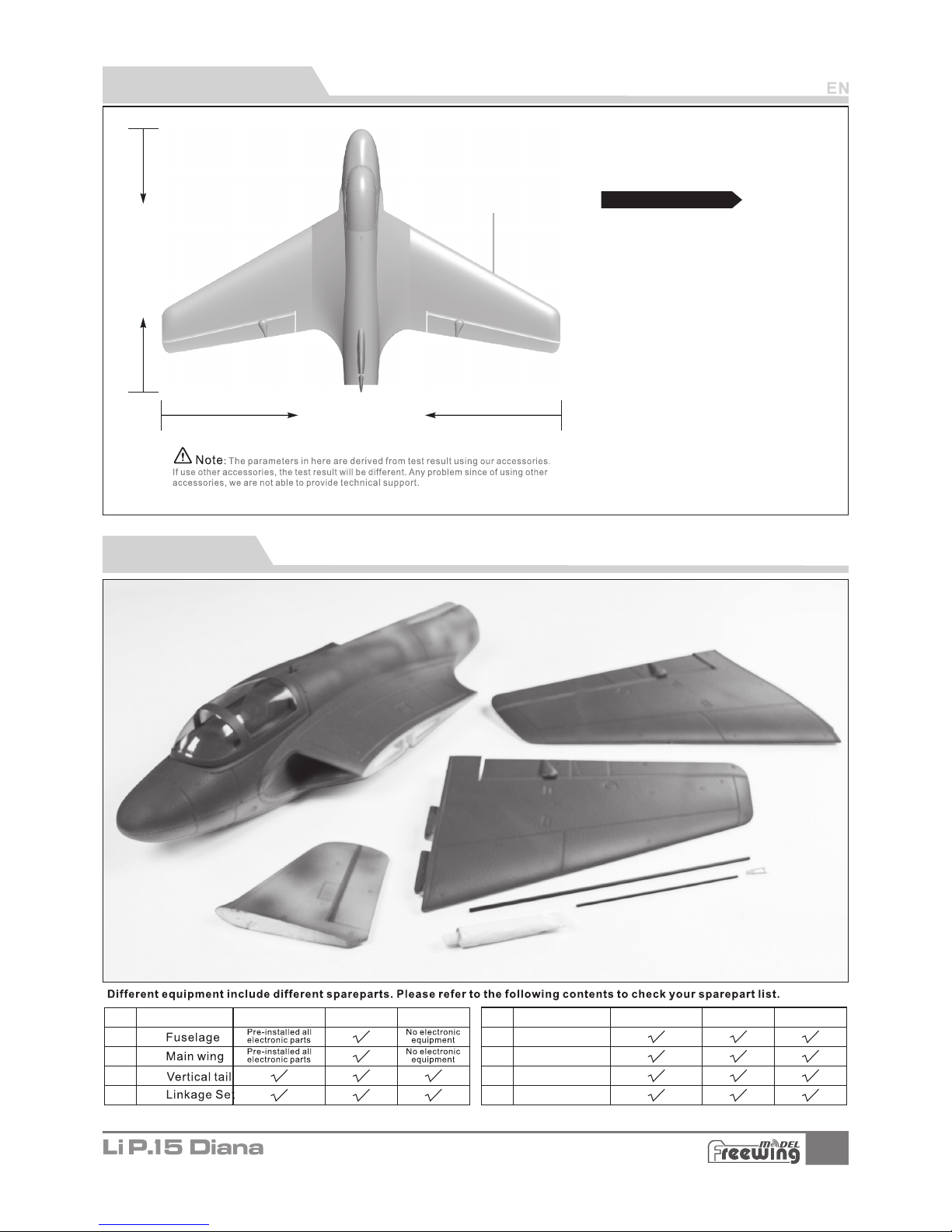
Product Overview
,
The pack age don t inc lude the lan ding gea r, if you need,pl ease con tact your local deal er.
Package List
No. Name
NameNo.
Antenn a
Carbon t ub e
Glue
User Man ua l
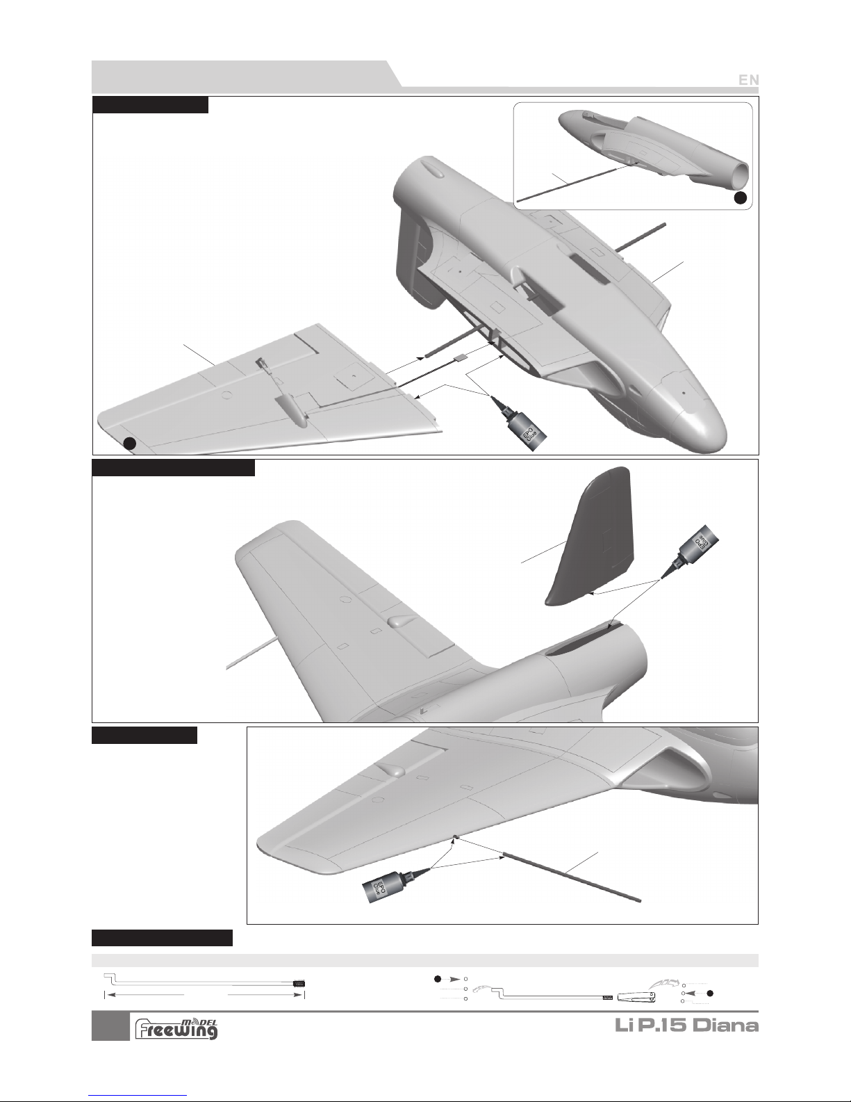
Inst all Mai n Wing
3
Step
2
Step
1
As sho wn in thi s photo :
1.In sert th e carbo n tube in to the fu selag e and keep
it in th e cente r.
2.As t he righ t photo s how, use g lue to in stall the
main w ing on th e fusel age.
Carb on tu be
(Ø4x32 0m mm m)
1.Us e glue to a ttach t he vert ical st abili zer on th e fusel age as th e
belo w photo s hown.
67. 8mm
(3- 1/16" )
Pus hrod di amete r Ø1.2m m
1
2
3
2
3
1
Ante nna
Ite m No.:F J11 0
PNP lns talla tio n Inst ruc tions
Fuselage
Main wing
Inst all Vert ical St abili zer
Verti cal sta biliz er
Inst all An tenna
Push rod Ins truct ions
Aileron p us hr od m ou nting h ol e
Aileron p us hr od s iz e

4
Battery cabin size:
L=110 W =46 H=43( mm)
Batt ery
58mm
(2-5/16")
Ite m No.:F J11 0
PNP lns talla tio n Inst ruc tions
Batt ery Siz e
Use rubberized non-slip tape
or hook-and-loop tape
Cent er of Gra vity
Corr ec t Center of G ra vity ( CG”) is c ritical f or t he aircra ft t o fly safely a nd in contr ol . ”
Plea se r efer to the f ol lowin g CG d iagram to a dj ust your pl ane’s Center of G ravity.
- You can mo ve t he batter y forward o r ba ckward to a dj ust the Cen ter of
Grav it y.
- If you c an not obtai n th e recom me nded CG
by mov in g the batte ry t o a suita bl e locatio n,
you ca n al so instal l a co unter we ight to ach ie ve
corr ec t CG. Howev er, w ith the r ec ommende d
batt er y size,no c ou nterw ei ght is requ ir ed. We
reco mm end not flyi ng w ith a bat te ry size tha t
requ ir es a counte rw eight .
”
Cock pit
P
ul
l t
h
e la
tch b
a
ck
a
nd o
pen t
he c
o
c
kp
i
t
.
Batt ery tra y
Velcr o
We recom mend th e follo wing Li Po batt ery:
3S 11.1 V 1000m Ah ~ 3S 11.1 V 1600m Ah
>
Disc harge r ate of C 30C
Befo re conn ectin g the bat tery an d recei ver, ple ase
swit ch on the t ransm itter p ower an d make su re
the th rottl e stick i s in the lo west po sitio n. Bind y our
rece iver to y our tra nsmit ter acc ordin g to your
tran smitt er’s instr uctio n manua l.
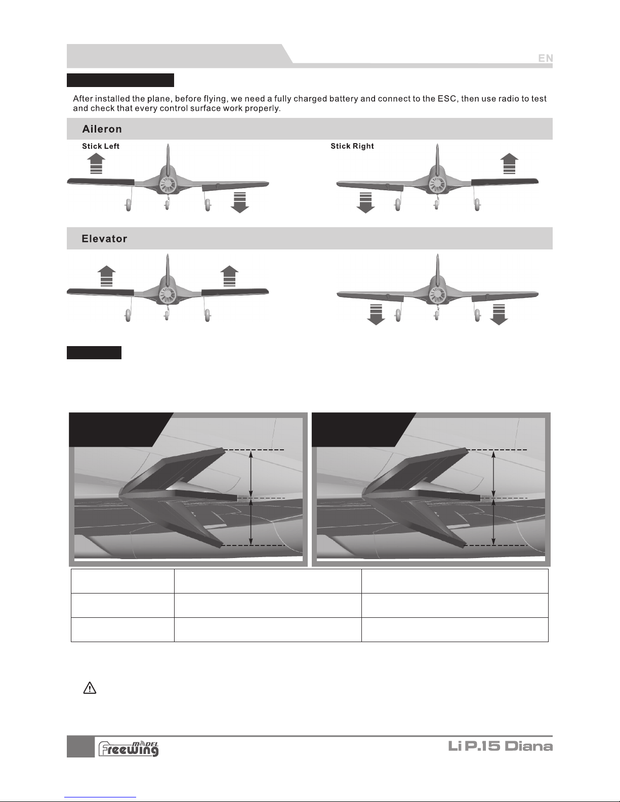
Cont rol Dir ectio n Tes t
5
H1
H2
H1
H2
H1/H2 11mm /11 mm
D/R Rate :6 0%
H1/H2 15mm/15mm
D/R Rate :8 0%
H1/H2 15mm/15mm
D/R Rate :8 0%
H1/H2 20mm/20mm
D/R Rate :1 00 %
Ite m No.:F J11 0
Dual R ates
Ac cor din g to our testing e xperience, us e the following para met ers to set Aileron/Elevator Rate.
Program your p ref err ed Exponential % in yo ur radio transmitter. We recommend using High R ate for the
first flight, and switching to Low Rate if you desire a lower sensitivity. On successive flights, adjust the
Rates and Expo to suit your preference.
升降舵
Stic k Down Stic k Up
PNP lns talla tio n Inst ruc tions
Aileron Elevator
Aileron(measured closes t
to the fusel age)
Elevator(measured closest
to the fuselage)
Low Rate
High Rate
Flig ht atte ntion : When full thr ot tl t o fly, the n os e will be down. p le as e se t up 1.5mm elev at or u p to a void the nose d ow n
phenom en on a nd maintian i ts i n th e sa me level.

6
1 2
2627 -4 50 0k v
Ite m No.:M O0262 72
2627 -4 500
11.1
28 750 4900 0 50E720 11 310
2.4
64mm
5-blade EDF
Weight
(g)
Power system
No.
Thru st (g)
Current(A)
Use voltage
(V)
Max power
(W)
Efficiency
(g/w)
EDF Fa ns
Motor
Specifications
(KV)
Rotating speed
(rpm )
Uni: mm
A
B
C
D
E
F
G
平 尾 组 装
Step
1
Step
2
Step
3
A
B
C
D
Refe r to the fo llowi ng phot o to inst all ESC a nd powe r syste m
A- ESC
B- 64m m EDF pow er syst em
C- EDF c over
D- Scr ew (PA2.3x16 2pc s)
Ite m No.:F J11 0
Moto r Speci ficati ons
Accessories Description
ABCDEFG-
Motor 2627-4500KV
64mm Outrunner ducted frame
Screw (PM2.5x6 2pcs)
Motor collet
Motor collet backplate
64mm 5-blade ducted fan
Nut
Moto r Overv iew
Stan dard ve rsion
Not e: W hen th e ESC and b atter y are co nne cted, avo id t ouc hi ng
the E SC by han d to avoi d accid ental i njury d ue to hea t When te sting t he
EDF, p le ase use sa fet y te st sta nd f or tes ti ng. Ne ver hol d an ED F un it i n
you r hand wh ile it is p owere d on.
Serv os Intr oduct ions
Main wing (L )
Main wing (R )
1
2
Positiv e
Positiv e
300m m
300m m
9g plasti c se rv o
9g plasti c se rv o
Servo reg ul at io n
Pos./Re v.
Cable len gt h
Positio n
No.
If you n ee d to purc ha se anothe r brand’s servo, pl ease
refe r to t he foll ow ing list to c hoose a sui ta ble ser vo .
Accessories Introduction

Spar e part na me and pa ramet ers
A B CDE F GHI J K -
Serv o fixed mo unt
9g Ser vo
Scre w (PWA 2. 3x 8 1pcs)
Set sc rew (M3 x3 4 pc s)
Nose w heel st rut fixe d piece
Nose w heel st rut (to p)
Whee l conne cting p art
Nose w heel st rut (bo ttom)
Nose w heel (Ø 35 x10mm)
Whee l chock
Nose l andin g gear
7
Step
1
A
B
C
E
F
D
Step
2
G
H
J
D1
D2
D3
I
Step
3
K
ABCDEF -
Main l andin g gear fix ed moun t
Rear g ear mai n strut
(Ø50 x1 5m m)Nose w heel
Whee l chock
(M3x 3)Set sc rew
Main l andin g gear do or
Step
1
A
B
C
D
E
Step
2
F
Ite m No.:F J11 0
Landing Gear Assemble
Land ing gea r is the op tiona l part, p lease c onsul t with th e local d istri butor t o purch ase, an d refer t o the
foll owing i nstru ction s to inst all.
Inst all nos e landi ng gear
Plea se refe r to the fo llowi ng phot o for ass embly a nd inst allat ion of th e landi ng gear.
Inst all rea r landi ng gear
Please refer to the following photo for assembly and installation
of the landing gear.
Spar e part na me and pa ramet ers
Atte ntion : insta ll the wh eel on
the di recti on of nos e fusel age.

Add.:FeiYi Building,face to Labor Bureau, Fumin Middle Road, Dalang Town,
Dongguan City,Guangdong Province, China
HK Freewing Model International Limited
东莞市 飞 翼 电 子科技有 限 公 司
香 港 飞 翼 模 型 国 际 有 限 公 司
地址: 广 东 省东 莞 市大朗 镇 富民 中 路40 2-4 0 8号 飞 翼楼四 楼
Web: http://www.sz-freewing.com
Email:freewing@sz-freewing.com
Tel: 86-769-82669669 Fax:86-769-82033233
Web: http://www.sz-freewing.com
Email:freewing@sz-freewing.com
Tel: 86-769-82669669 Fax:86-769-82033233
Dongguan Freewing Electronic Technology Ltd
R
 Loading...