

Page 1
EN 1~8
中
9~16
User Manual
Page 2
Introduction
Basic Product Information
Package List
PNP Install Insturctions
Install Main Wing
Install Horizontal Stabilizer
Install Vertical Stabilizer
Install Pushrod
Pushrod instructions
Battery Size
1
2
2
3
3
4
4
5
5
Center of Gravity
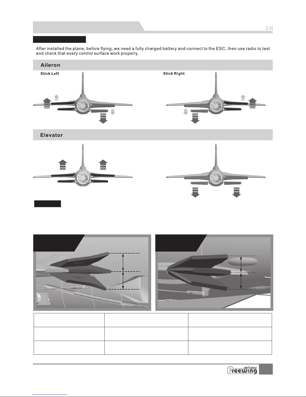
Control Direction Test
Dual Rates
Accessories Description
Motor Specifications
Motor Overview
Accessories Introduction
Servos Introductions
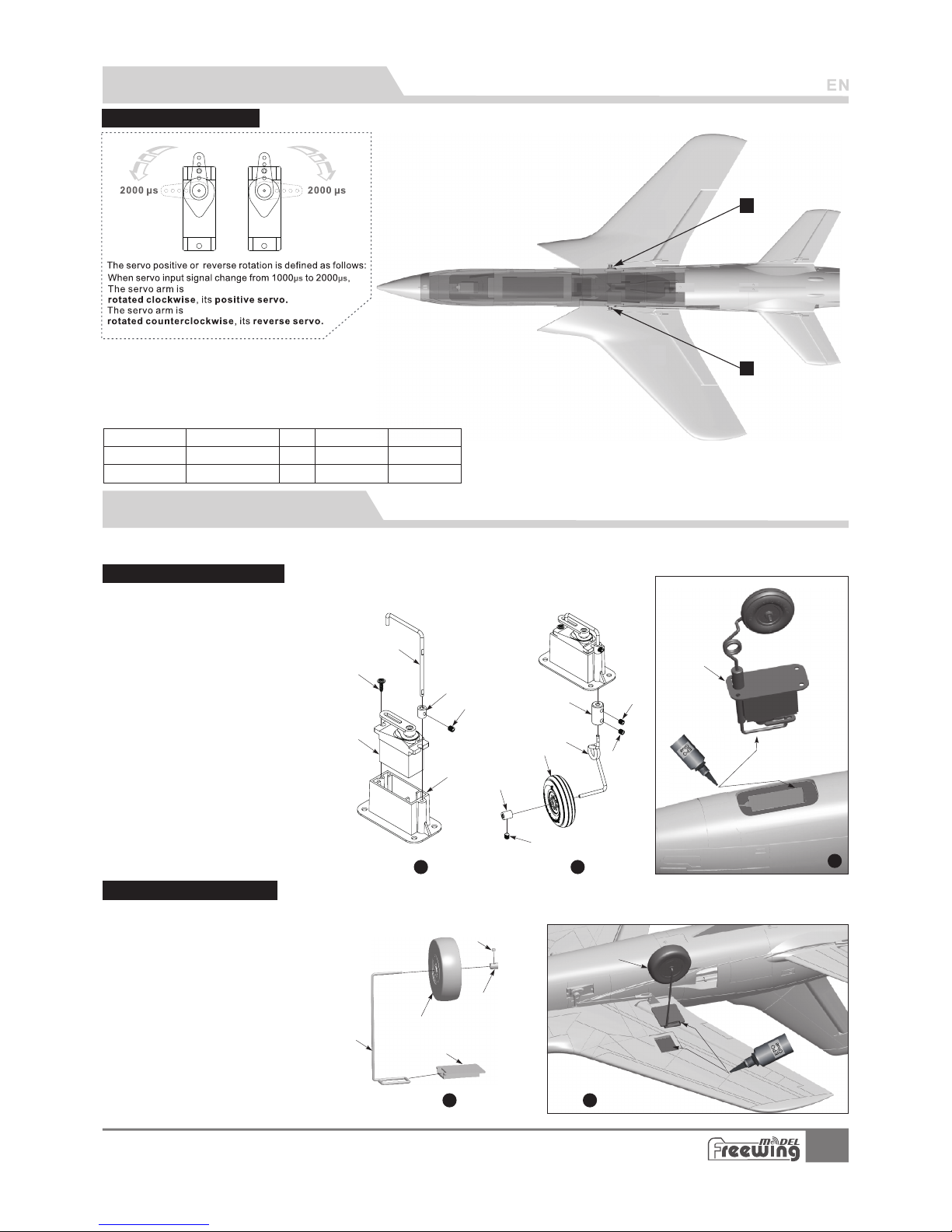
Install nose landing gear
lnstall rear landing gear
1
Ite m No.:F J10 9
F-105 Thunderchief
Catalog
5
6
6
7
7
8
8
8
Page 3
Contents
PNP
ARF Plus
Airframe
1
2
3
4
2
Ite m No.:F J10 9
F-105 Thunderchief
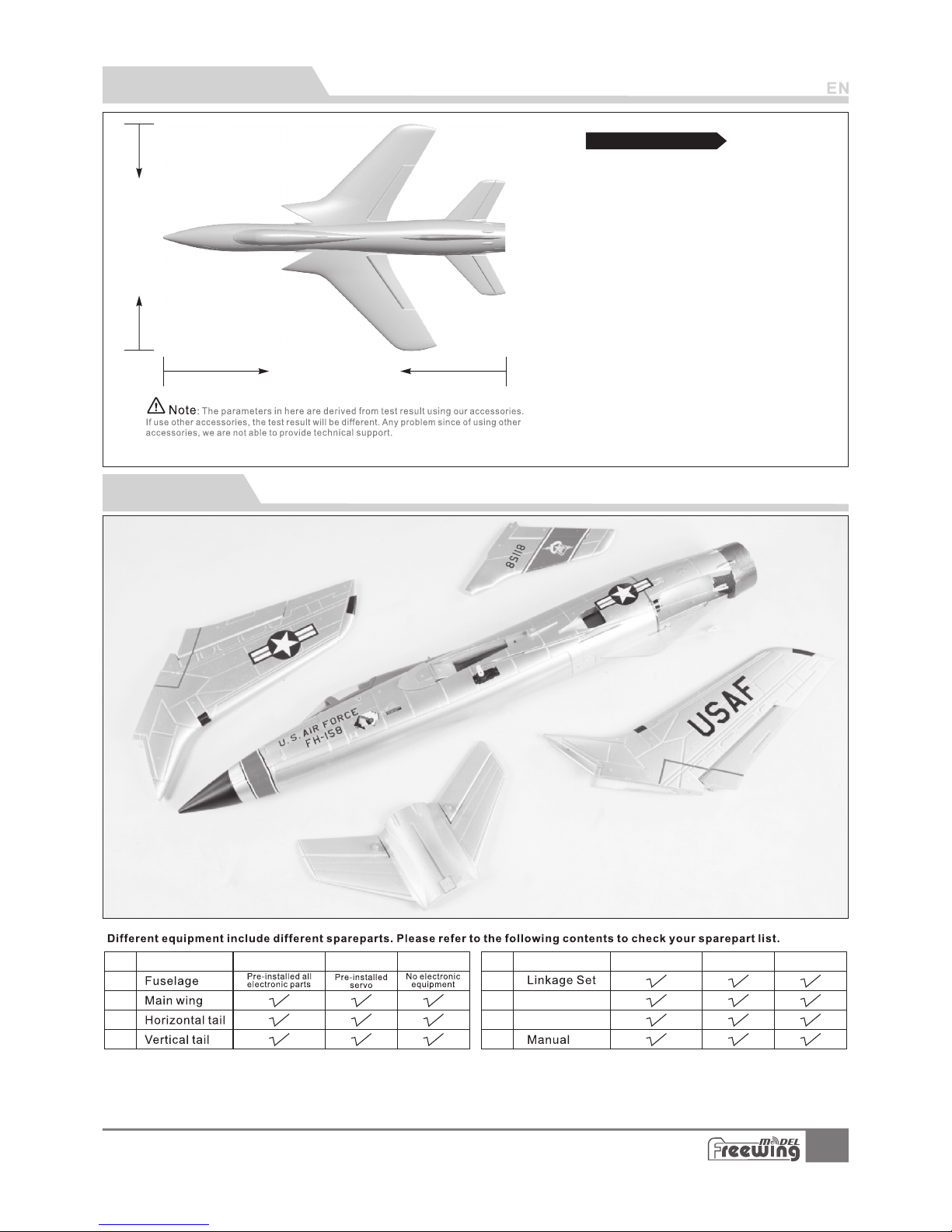
Product Overview
800mm(3 1.5")
530mm(2 0.8")
2
Wing Loading :70g/dm
2
WingArea:7dm
Motor:2627-4500KV
Brushless Ou trunn er Motor
Ducted fan: 64 mm 5-Bl ade Fan
ESC: 30A Brushl ess
Servo: 9g Plas tic Ser vo (2pc s)
Top Speed : 120KPH /75MP H
Empty Weight:360g(wi thout batt ery)
Bench Tested Thrust: 750 g
Landing gear : fixed la nding g ear
(Op tiona l spare p art, ne ed to pur chase s epara tely.)
Standard ver sion
,
The pack age don t includ e the landing gea r, if you need,please contact your loc al dealer.
No. Name
5
6
7
8
PNP
ARF Plu s
Airfr ame
No. Name
Glue
Fin
Page 4
3
Ite m No.:F J10 9
F-105 Thunderchief
Step
1
Step
2
Carbon tu be
(Ø4x200m m)
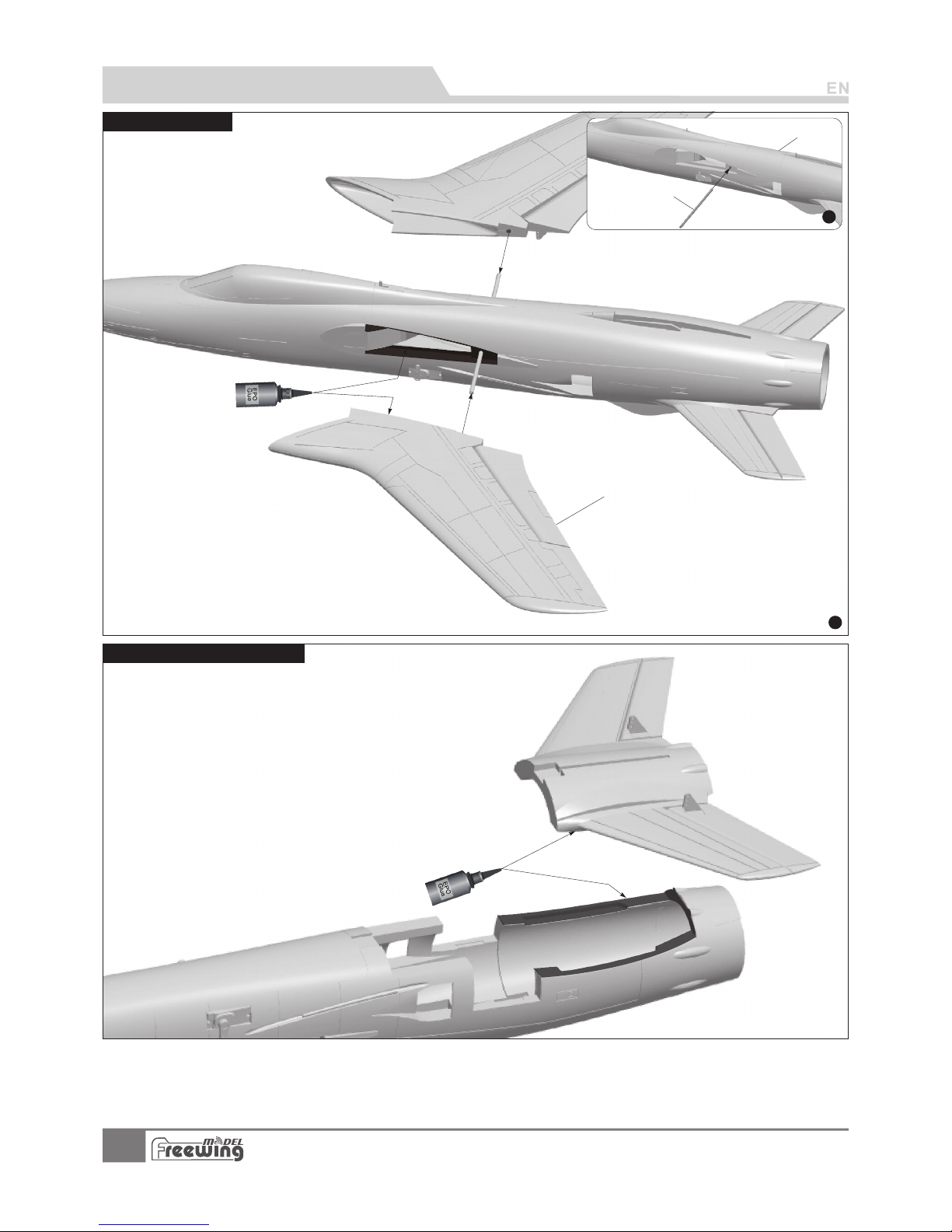
As shown in this p hoto:
1.Insert the c arbon t ube int o the fuselage and keep
it in the center.
2.Apply the glue on the m ain win g insta ll position of
fuselage (In dicat ed posi tion as the photo shown),
then install t he main w ing on th e fuselage and wait for it sol idify.
Fuselage
Main wing
1.Use glue to at tach th e horiz ontal tail on the fuselage a s the
below photo sh own.
PNP lnstal l ation Instructio n s
Install Main W ing
Install Hori zonta l Stabi lizer
Page 5
4
Ite m No.:F J10 9
F-105 Thunderchief
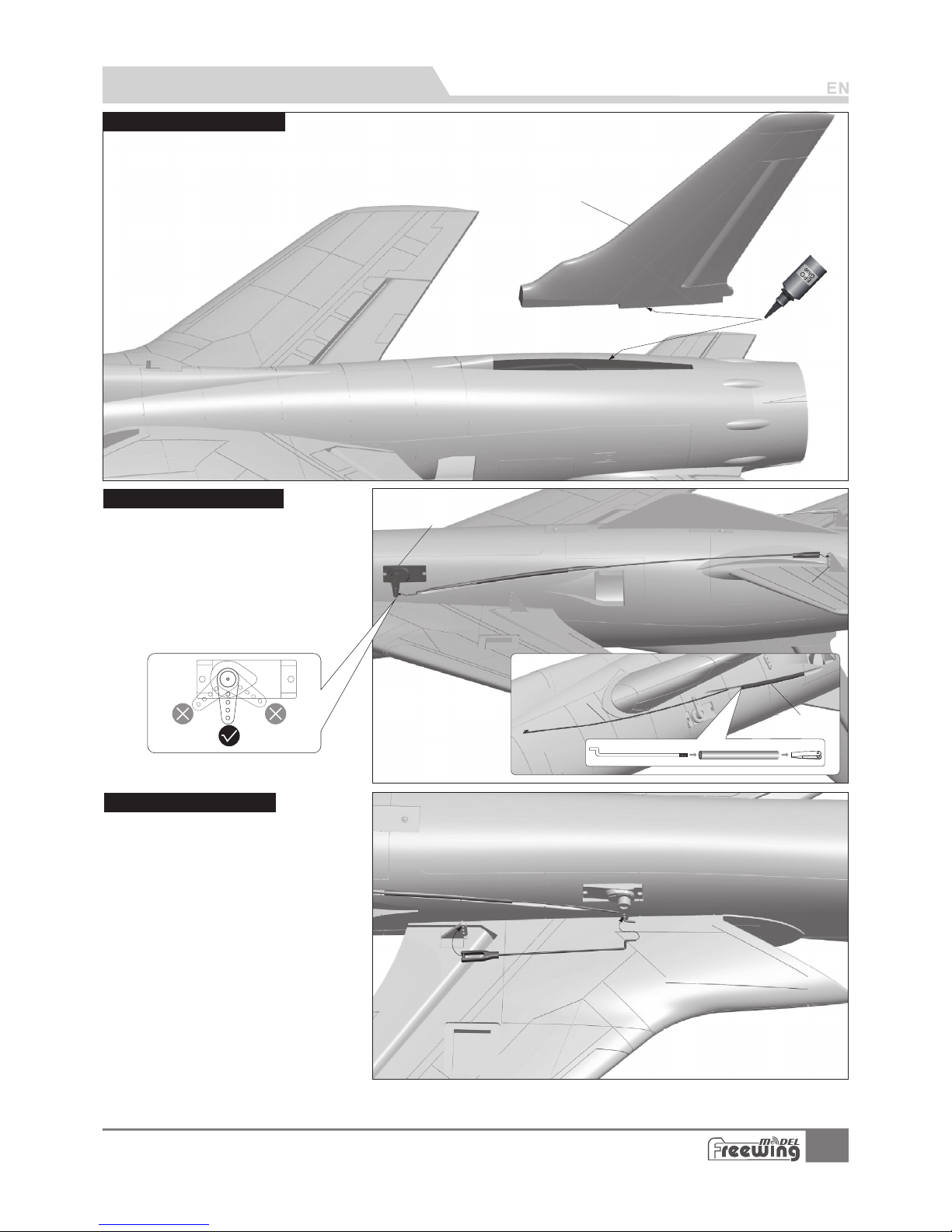
Use glue to inst all the v ertic al stabilizer on the rear fu selag e. Ensu re it is 90 degrees to
the horizont al plan e of the fu selage. A crooked ver tical s tabil izer will hinder flight.
A
B
C
D
ABCD-
Elevator pus hrod
Plastic tube
9g Servo
Elevator hor n
A
B
C
Vertical stab ilize r
PNP lnstal l ation Instructio n s
Install Verti cal Sta biliz er
1.Use a servo tester or radio to center
each servo.
2.Insert the threaded side of the rod to
the plastic tube and tighten the clevis.
3.One side pushrod insert to the servo
arm,adjust its length .And insert the
clevis to the elevator pushrod horn.
4.Repeat these 3 steps for the other side.
1 Use a servo test er or rad io to cen ter .
each servo.
2.One side pushrod in sert to t he serv o
arm,adjust i ts leng th.An d insert the
clevis to the ai leron p ushro d horn.
3.Repeat these 2 step s for the o ther si de.
Install Elev ator pu shrod
Install Ai leron p ushrod
Page 6
5
Ite m No.:F J10 9
F-105 Thunderchief
323 mm
(12 -6/8" )
Pus hrod di amete r Ø1.0m m
1
2
3
2
3
1
Pus hrod di amete r Ø1.2m m
86m m
(3- 3/8")
1
3
1
2
2
3
365mm
(14-3/8")
PNP lnstal l ation Instructio n s
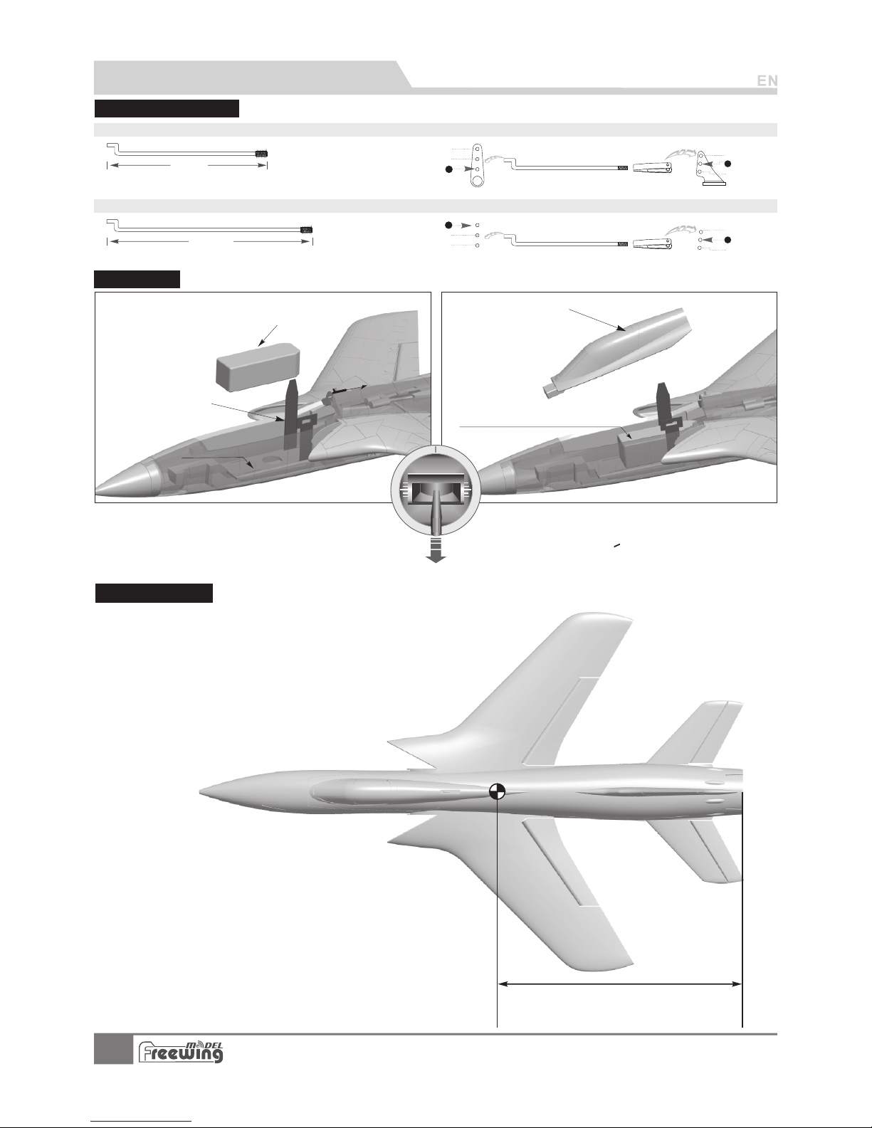
Pushrod Inst ructi ons
Elevat or pu shr od size
Elevat or pu shr od mounti ng ho le
Ailero n pus hro d mountin g hol e
Ailero n pus hro d size
Battery cab in size:
L=150 W=42 H=42.5(m m)
Cockpit
Battery
Velcro
Battery tray
Use rubberized non-slip tape
or hook-and-loop tape
P
u
ll th
e l
at
c
h b
ac
k
and o
p
en th e c
o
c
kpi t
.
Battery Size
We recommend the followi ng LiPo b atter y:
3S 11.1V 1000mA h ~ 3S 11.1V 2 200mA h
>
Discharge ra te of C 30C
Before conne cting t he batt ery and receiver, please
switch on the tr ansmi tter po wer and make sure
the throttle s tick is i n the low est position. Bind your
receiver to yo ur tran smitt er according to your
transmitte r’s instruction manual.
Center of Grav ity
Corre ct Center of Grav ity ( CG”) is c rit ical for the a ircraft to fly saf ely and in con tro l. ”
Pleas e refer to the foll owing CG dia gra m to adjust yo ur plane’s Center of G ravity.
- You can mov e the battery for ward or back war d to adjust th e Center of
Gravi ty.
- If you ca nnot obtain the r ecommend ed CG
by movi ng the battery to a s uitable lo cat ion,
you can a lso install a cou nterweig ht to a chieve
corre ct CG. However, wi th the recom men ded
batte ry size,no coun terweigh t is re quired. We
recom mend not flying wi th a battery s ize t hat
requi res a counterwe ight.
”
Page 7
H1
H2
H1
H2
H1/H2 7mm/ 7mm
D/R Rate:7 5%
H1/H2 9mm/ 9mm
D/R Rate:1 00%
H1/H2 13mm /13 mm
D/R Rate:7 5%
H1/H2 15mm /15 mm
D/R Rate:1 00%
升降舵
舵 面 测 试
6
Ite m No.:F J10 9
F-105 Thunderchief
PNP lnstal l ation Instructio n s
Control Dire ction Test
Stick Down Stick Up
Aileron Elevator
Low Rate
High Rate
Dual Rates
Accordin g to o ur testing experience, use the following parameters to set Aileron/Elevato r Rate.
Program your preferre d Expo nential % in your radio transmitter. We recommend using High Rate f or the
first flight, and switching to Low Rate if you desire a lower sensit ivity. On successive flights, a djust the
Rates and Expo to suit you r preference.
Aileron(mea sured closest
to the fuselage)
Elevator(measured closest
to the fuselage)
Page 8
A
B
C
D
E
F
G
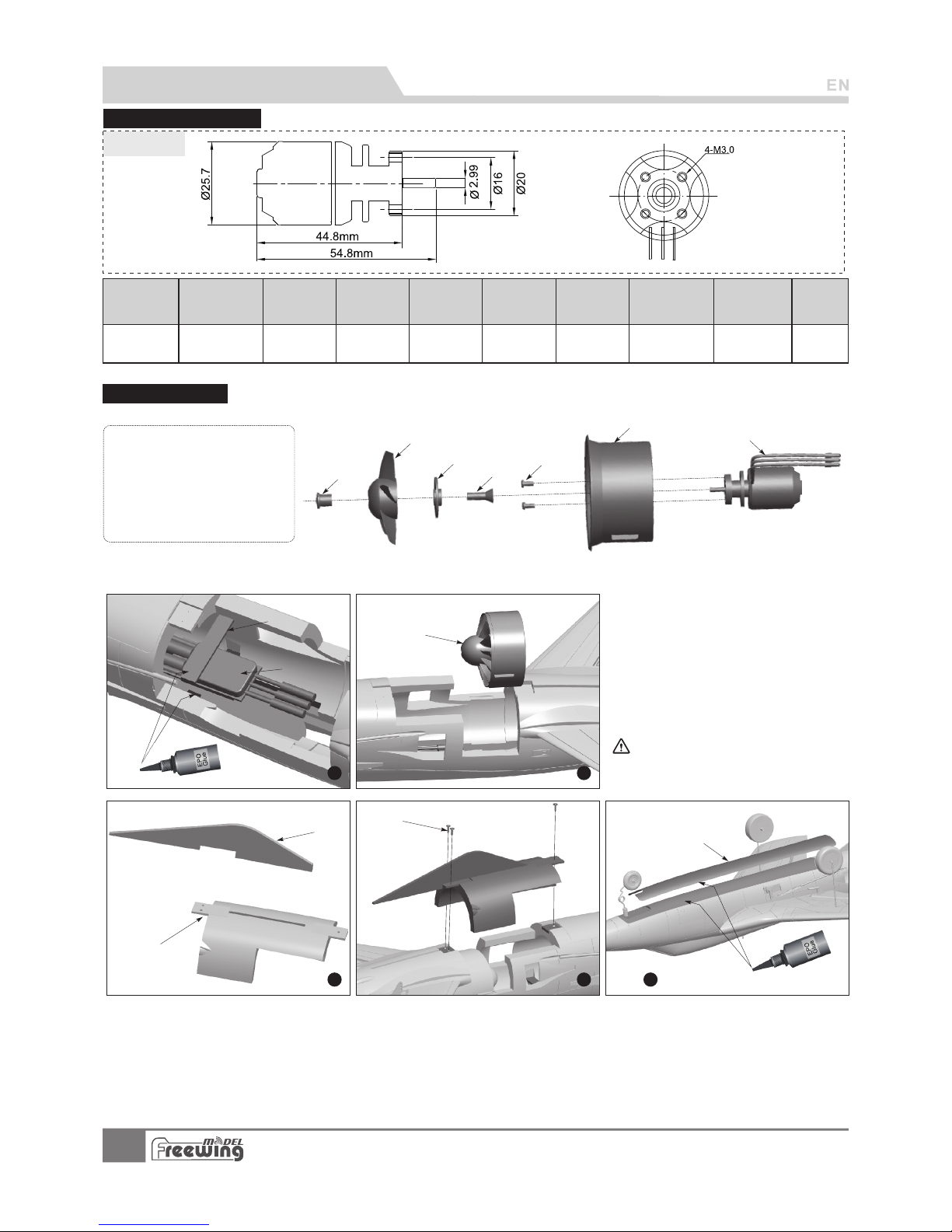
As the left diag ram, in stall E SC
and power syst em
ABCDEFG-
ESC fixed wood pi ece
ESC
64mm EDF power s ystem
Fin
EDF cover
Screw (KA2.3x8)
Fuselage cov er
2627-4500
Ite m No.:M O0262 72
7
Ite m No.:F J10 9
F-105 Thunderchief
C
A
B
E
D
F
G
Step
1
Step
2
Step
3
Step
4
Step
5
2627- 4500
11.1(3S)
28
64mm
5-blade EDF
750 49000 50E7201 310 2.4
Weight
(g)
Power system
No.
Thrus t(g)
Current(A)
Use voltage
(V)
Max power
(W)
Efficiency
(g/w)
EDF Fan s
Motor
Specifications
(KV)
Rotating speed
(rpm)
Motor Specifi catio ns
ABCDEFG-
Motor 2627-4500KV
64mm Outrunner ducted frame
Screw (PM2.5x6 2pcs)
Motor collet
Motor collet backplate
64mm 5-blade ducted fan
Nut
Motor Overvi ew
Standard ver sion
Note: W hen th e ESC an d batt ery are c onnec ted,
avo id touc hing t he ESC by h and to a void accid enta l
inj ury due to heat Whe n t esti ng the ED F, plea se use
saf ety test stan d fo r t esti ng.N ever hold an EDF unit in
you r hand wh ile it is p owere d on.
Accessories Description
Page 9
1
2
8
Ite m No.:F J10 9
F-105 Thunderchief
Accessories Introduction
Servos Intro ducti ons
Main win g(L )
Main win g(R )
1
2
Positi ve
Positi ve
300mm
300mm
9g plast ic se rvo
9g plast ic se rvo
Servo re gul ati on
Pos./R ev.
Cable le ngt h
Positi on
No.
If you ne ed to purcha se an other bran d’s serv o, please
refer t o the follow ing l ist to choos e a suitable s ervo.
Step
1
A
B
C
E
F
D
Step
2
G
H
J
D1
D2
D3
I
Step
3
K
Spare part nam e and par amete rs
A B CDE F GHI J K -
Servo fixed mou nt
9g Servo
Screw (PWA 2.3 x8 1p cs)
Set screw (M3x 3 4pc s)
Nose wheel str ut fixed p iece
Nose wheel str ut (top )
Wheel connec ting pa rt
Nose wheel str ut (bot tom)
Nose wheel (Ø3 5x1 0mm)
Wheel chock
Nose landing g ear
Install nose l andin g gear
Please refer t o the fol lowin g photo for assembly and ins talla tion of t he landing gear.
ABCDEF -
Set screw (M3x3)
Wheel chock
Nose wheel (Ø5 0x1 5mm)
Rear gear main s trut
Main landing g ear fixe d mount
Main landing g ear doo r
Step
1
Step
2
A
B
C
D
E
F
Attention: i nstal l the whe el on
the directio n of nose f usela ge.
Please refer to the following photo for assembly and installation of the landing gear.
Install rear l andin g gear
Spare part nam e and par amete rs
Landing Gear Assemble
Landing gear i s the opt ional p art,please cons ult wit h the loc al distributor to p urcha se, and r efer to the
following in struc tions t o install.
Page 10

Add.:FeiYi Building,face to Labor Bureau, Fumin Middle Road, Dalang Town,
Dongguan City,Guangdong Province, China
HK Freewing Model International Limited
东莞 市 飞翼 电子 科技 有 限公 司
香 港 飞 翼 模 型 国 际 有 限 公 司
地址: 广东省东 莞 市 大朗镇富民 中 路402-408号飞翼楼四 楼
Web: http://www.sz-freewing.com
Email:[email protected]
Tel: 86-769-82669669 Fax:86-769-82033233
Web: http://www.sz-freewing.com
Email:[email protected]
Tel: 86-769-82669669 Fax:86-769-82033233
Dongguan Freewing Electronic Technology Ltd
R
 Loading...