

Page 1
Page 2
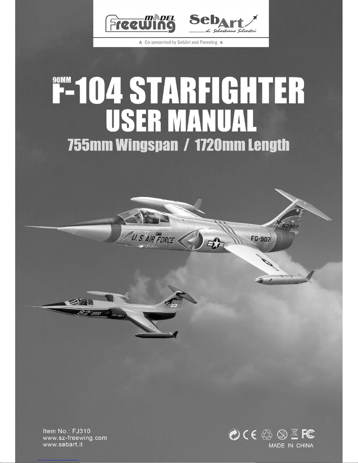
The famous Lockheed F-104 Starfighter has been recreated in this amazing 90 mm EDF jet. Following up on their
popular 70 mm variant, Freewing has answered the customer demands for a 90mm Super Scale version of this iconic jet
fighter.
Co-presented by SebArt and Freewing, the F-104 Starfighter 90 mm EDF jet is constructed with EPO foam,
with a wingspan of 755mm and a length of 1720mm and is available in two different color schemes. The silver color
scheme of the George Air Force Base's 479th Tactical Fighter Wing FG-907, and the yellow/black Italian Air Force 82th
anniversary paint scheme .
Other than some small adjustments in main wing and horizontal stabilizer shape, to increase its flight stability,
we have replicated the original shape of the F-104 as well as using a scale afterburner, warning lights and landing lights to
make the airplane more realistic looking during flight. The aluminum shock absorbing landing gear incorporates an electric
worm controller to effectively reduce the impact on landing . Fiberglass material is incorporated to make the nose and
main landing gear doors lighter to reduce weight as well as reduce its wind resistance during flight. A specially designed
air-brake will allow more airflow during flight, and help reduce landing speed. All this In addition to the many scale details
such as the scale pilot, instrumentation sticker, pitot tube…etc.
The main wing, horizontal stabilizer, vertical stabilizer all can be easily removed for transport. In order to enhance
the overall strength, several carbon tubes are located in the main wing, horizontal and vertical stabilizers as well as 2x16g
metal gear servos, 7x17g metal servos and 3x9g metal servos all using ball link connectors to increase flight stability.
The pre-installed 90mm 12-blade ducted fan with 3748-1550KV brushless motor and Hobbywing 130A (8A UBEC) ESC
gives it a great sound combined with powerful thrust and the use of a control board creates a less cluttered battery
compartment .
The 90mm F104S “Starfighter” comes with a Freewing 3-axis Gyro (E51) pre-installed to further increase its
flight stability. During flight, its excellent speed and climb performance can easily emulate conventional tactical
flight maneuvers. With the F104's special aerodynamic shape, a long glide path with the air speed brakes and
about 30 degrees elevation angle is needed to decelerate for landing.
1
R
Item N o.:FJ310
F-104S Starfighter
Index
EN
Introduction
Product Basic Information
Package list
Assembly
Nose cone Installation
Air-brake Installation
Landing gear Installation
Gear door Installation
3-Axis Gyro Introduction and use
1
2
2
3
6
6
7
10
11
Control board Introduction and use
Servo introduction
Battery
Installation
Center of Gravity
Motor Parameters
Power system Installation
Control direction test
Dual Rates
12
12
13
13
13
14
15
16
1. This is not a toy! Operators should have some basic experience. Beginners should operate only under the guidance
of a professional instructor.
2. Before beginning assembly, please read through the instructions and carefully follow them throughout the build.
3. Freewing and it's vendors will not be held responsible for any losses due to improper assembly and operation.
4. Model airplane operators must be at least 14 years of age.
5. This airplane is made of EPO foam material, covered with surface spray paint. Don't use chemicals to clean as it may
cause damage.
6. You should avoid flying in areas such as public places, areas with high voltage power lines, nearby highways, airports
or in other areas where laws and regulations clearly prohibit flight.
7. Do not fly in bad weather conditions, including thunderstorms, snow, etc...
8. Lipo batteries should be properly stored in a fire proof container and be kept at a minimum of 2M distance away from
flammable or explosive materials.
9. Damaged or scrap batteries must be properly discharged before disposal or recycling to avoid spontaneous
combustion and fire.
10. At the Flying Field, properly dispose of any waste you have created, don't leave or burn your waste.. Ensure that
your throttle is in the low position and that your radio is turned on before connecting the Lipo battery.
11. Ensure that the throttle is in the lowest position and transmitter is turned on, before connecting a Lipo Battery to
the ESC of the aircraft.
12. Do not try to catch the airplane while in flight or during landing. Wait for the airplane to come to a complete stop
before handling.
Page 3
2
R
PNP
KIT Plus
Airfr ame
PNP
KIT Plus
Airfr ame
Item N o.:FJ310
F-104S Starfighter
1
2
3
4
5
6
7
8
9
10
Fuselage
Main wing
Tail wing set
Rudder
Nose cone
Fuel tank
Hardware
Carbon rods
Glue/Decals
Manual
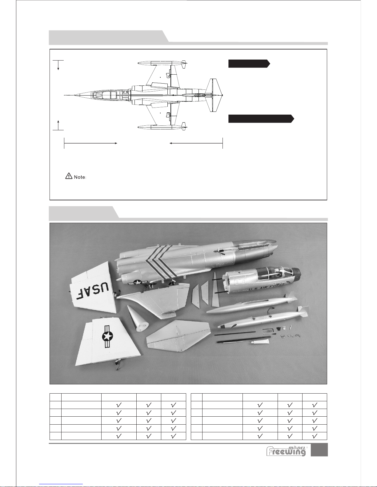
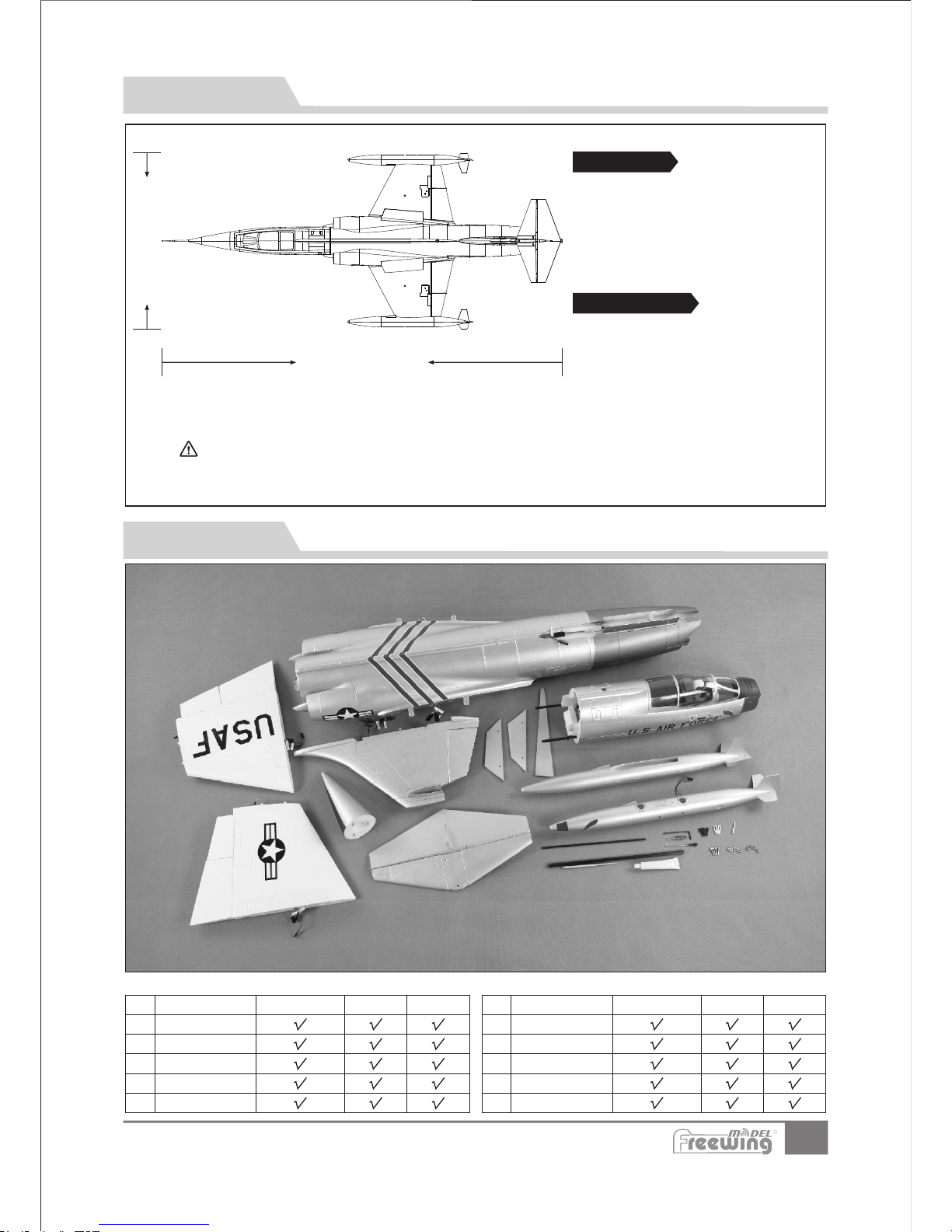
Different types of kits will come with certain specific parts. Refer to the list of parts for your type of kit in the chart below.
Product Basic Information
EN
Package list
NO.
Part Name Part Name
NO.
1720mm(67.7in.)
755mm(29.73 in.)
Specifications
Required to Complete
·
·
·
·Take-off weight:
2800g (99 oz.) w/o battery
·Thrust:3150g (112 oz)
Ducted Fans:12-Bladed 90mm EDF
·Motor:3748-1550KV
Brushless out-runner motor
·ESC:130A ESC With UBEC 8A
·Servo:9g*3pcs,16g*2pcs,17g*7pcs
7-channel Transmitter and Receiver
(minimum)
·6 Cell 5000mAh-6000mAh Li-po battery Lipo
battery charger
The parameters stated here are derived from test results using our accessories.
If you use other accessories, the test results will differ. We cannot provide technical
support if you have a problem when using other accessories.
Page 4
3
Item N o.:FJ310
F-104S Starfighter
;
A
B
C
3
Step
1
2
D
E
F
Assembly
Main Wing
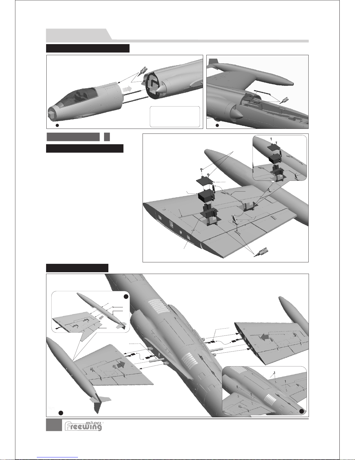
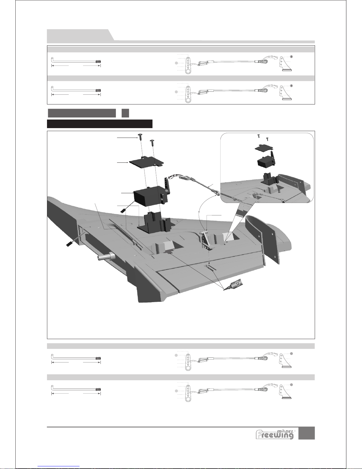
Main Wing Servo Installation
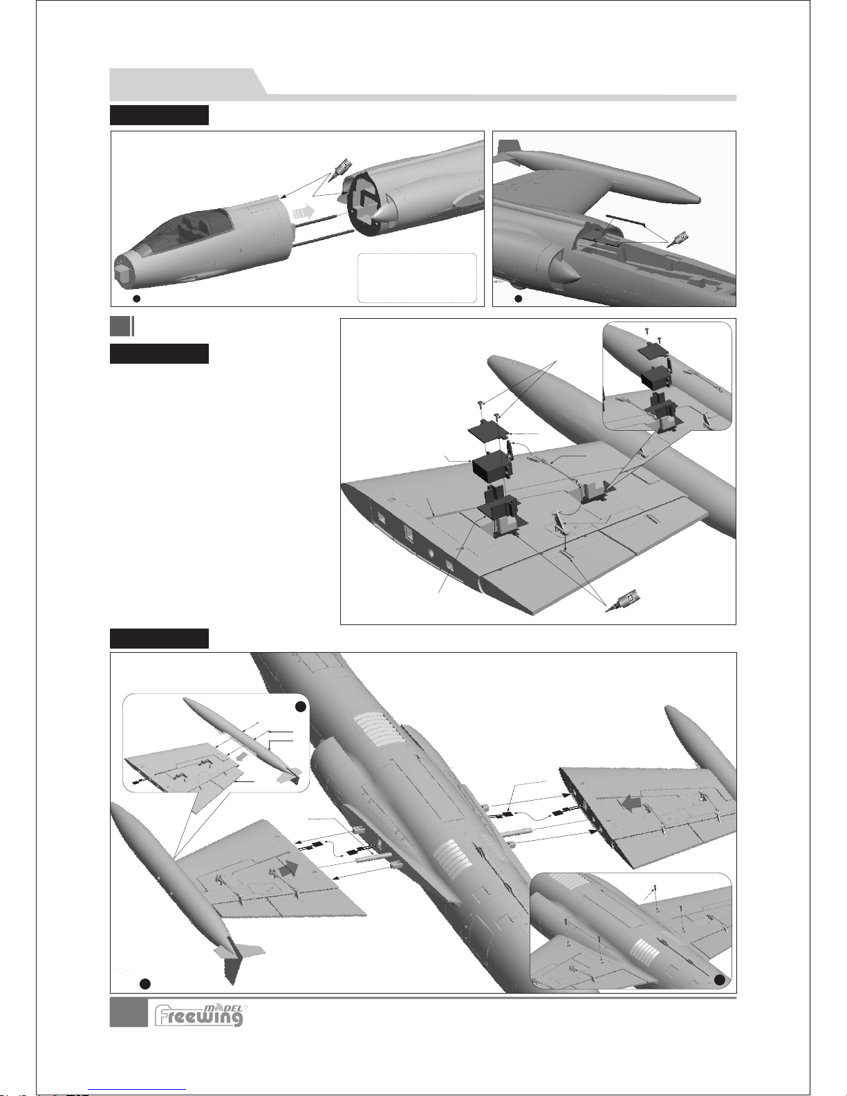
1.
2.
3.
Use a servo tester or radio to center
the servo arm.
Use glue to anchor the 17g servo
box (C) and control horn(D)to the
main wing.
Place the 17g servo into the servo
box(C),and press the servo cable into
the servo cable trough (F), position the
17g servo cover(B) and use 2
screws(A), to secure the servo cover.
Connect pushrod (E) to the Servo Arm
and adjust its length so the control
surface is in the neutral position. Then
lock the clevis over the ball link on the
control horn (D)
A-Screw
B-Servo cover
C-Servo box
D-Horn
E-Pushrod
F-Servo cable trough
(PWA2x 8mm 4 pcs )
Servo
Step
Step
Main Wing Installation
EN
A
B
D
E
C
F
Note:There is EPO glue included
with the kit. . The glue should be
spread evenly then let it set for 90
seconds before joining the parts for
best glue strength.
Use glue and the Carbon rods to join the front and rear
fuselage sections. Carbon rods:Ø6x180mm 2pcs
1 2
Step Step
Carbon rods:Ø4x100mm 2pcs
Glue the carbon rods into the trough.
R
Front/Rear Fuselage Assembly
4.
1. Connect the servo cables to the fuselage extension cable.
2. Slide the main wings onto the fuselage.
3. Use 4 screws to secure the main wings.
A- Screws (PA3x8mm 4pcs)
B- Fuel tank
C- Main wing
D- Carbon rod (08x300 mm)
E- Servo/LED light extension cable
F- Screws (PM3x14mm 4 pcs)
Page 5
Ailer on pushr od size Ailer on pushr od mounti ng hole
Fl ap pus hro d siz e Flap pus hro d mou nti ng hol e
4
Item N o.:FJ310
F-104S Starfighter
Pus hrod di amete r:Ø1 .5m m
1
2
3
4
5
1
2
3
1
2
3
4
5
1
2
3
A
B
C
E
D
F
Pushrods
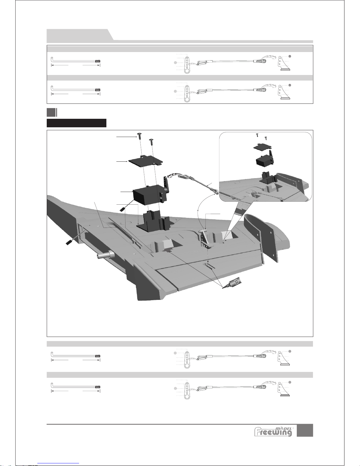
1. Use a servo tester or radio to center the servo arm.
2. ;
3. Place the servo into the 17g servo box(C),and press the servo cable into the cable trough (F).
4. Place the 17g servo cover(B) over the servo and use 2 screws(A)to secure it.
5. Connect pushrod (E)to the servo arm and adjust its length so the control surface is in the neutral
position then snap it over the ball link on the rudder control horn(D).
Use glue to attach the 17g servo box(C) and control arm(D)to the elevator and rudder.
Servo
Elevator and rudder
Elevator and Rudder Servo Installation
El evat or push rod size
Rudde r pushro d size
El evat or push rod moun tin g hole
Rudde r pushro d moun ting ho le
EN
A-Screws
B-Servo cover
C-Servo box
D-Rudder horn
E-Rudder pushrod
F-Servo cable trough
(PWA 2x8 mm 4p cs)
Pus hrod di amete r:Ø1 .5m m
Servo arm
Servo arm
58m m
(2. 28 in)
80m m
(3. 15 in)
1
2
4
5
70m m
(-2/3")2
2
3
1
2
3
4
5
70m m
(2-2/3")
2
3
3
Pus hrod di amete r:Ø1 .5m m
Pus hrod di amete r:Ø1 .5m m
Servo arm
Servo arm
R
Page 6

5
Item N o.:FJ310
F-104S Starfighter
A
B
Carbon rod(Ø4x200mm)
1
A
B
C
Screws(FWA3x8 4pcs)
A-Horn
B-Elevator pushrod
C-Elevator servo
2
43
EN
Assembly
Step
Step
Step Step
A-Elevator
B-Rudder
Horizontal Stabilizer Installation
Please refer to the following photos to install the Horizontal Stabilizer.
A
B
C
D
A-Carbon rod
B-Screws
CD- Rud der
(FA3x8 4pcs)
Rear fuselage
5
Step
R
Page 7
6
Item N o.:FJ310
F-104S Starfighter
Magnet
1
A
2
B
C
3
4
E
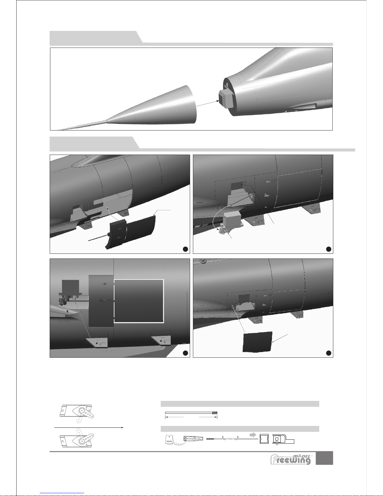
1. Use a servo tester or radio to center the
servo.
2.Use glue to attach the speed brake set (A) to both sides of the fuselage.
3.Use glue to attach servo(B) to the servo mount(C).
When installing, please note:
4.Ensure the servo and fuselage extension cables are properly attached and secure.
5.Insert the pushrod into the bolt of servo arm.
4.Keep the air brakes in the closed position, and tighten the screw of the bolt.
5.Test the system to make sure it is operating properly. Use glue to attach the servo
box cover in order to protect servo.
move forward toward the nose
EN
Air-Brake Installation
Step Step
StepStep
(1. 97in)
50m m
Rotating the pushrod,will increase
or reduce it's length.
Air-br ake pu shr od si ze
Air-br ake pu shr od mo unt ing ho le
Pus hrod di amete r:Ø1 .5m m
AB-16g Servo
C-Servo hard point.
Air-brake set
E-Servo cover
D-Pushrod
EN
Nose Cone Installation
Since a magnet is used to secure the nose cone, all you
need to do is to put it in place.
R
Page 8
7
Item N o.:FJ310
F-104S Starfighter
A
B
D
C
( 3.7 8in)
96m m
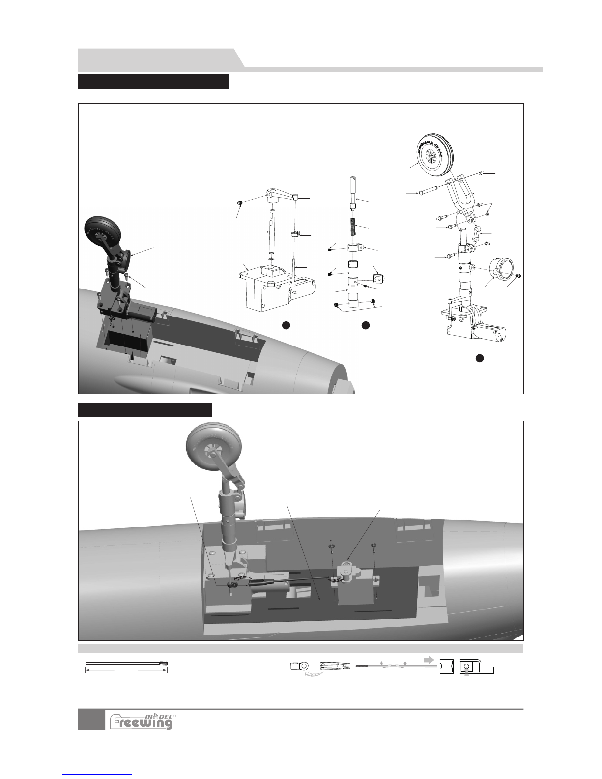
Please assemble and disassemble the nose gear by referring to the following photo.
Acces sor ies n ame and spec ifi cat ion
A- electric retract
B- Nose gear steering pushrod
C- Nose gear steering control ring
D- Nose gear metal shaft
E- L-shape arm
F-Grub screw
G-Grub screws
H-Nose landing gear main strut
I-Screw
(M3×3mm 1pc)
(M4 ×4m m 2pc s)
(PM2×3mm 1pc)
Nose gear assembly installed
Screws(PWA3x12 4pcs)
Nose gear mount
PQ
R
S
T
R1
S1
U
V
X
W
AB
3
Nose Gear Assembly
A
B
C
D
E
1
F
Step
G
H
I
K
J
M
L
N
O
2
Step
Step
M-Screw
N-Spring
O-Damping lever
P-Screw
Q-LED light
R-Pin
J-Screw(PM2x4mm) KLED light attachment arm
L-U-shape damping arm.
(PM2x3mm)
(PA2 ×8m m)
(Ø3.5x9.2mm)
STUV-
W-
X-
AB-
E-clip
8-shape connecting arm
Pin
U-shape slant supporting rod
Wheel shaft
E-clip
Wheel
(Ø1.5mm)
(Ø3.5x11.3 mm)
(Ø5x25.5mm)
(Ø2mm)
(Ø45x16mm)
Nose st eer ing p ushrod siz e
Servo p ush rod i nstallin g hol e
Rotating the pushrod,will increase
or reduce it's length.
Pus hrod di amete r:Ø1 .5m m
Landing gear Installation
EN
Nose gear servo Installation
R
A- Screws (PMA2x8mm 2pcs)
B- Servo
C- Landing gear pushrod
D- Nose gear hard point
Page 9
Note:When installing, check that the flat position of the part is aligned with the Grub screw hole. The flat position must face
the hole in order for the Grub screw to lock the part in place and ensure it does not come loose.
8
Item N o.:FJ310
F-104S Starfighter
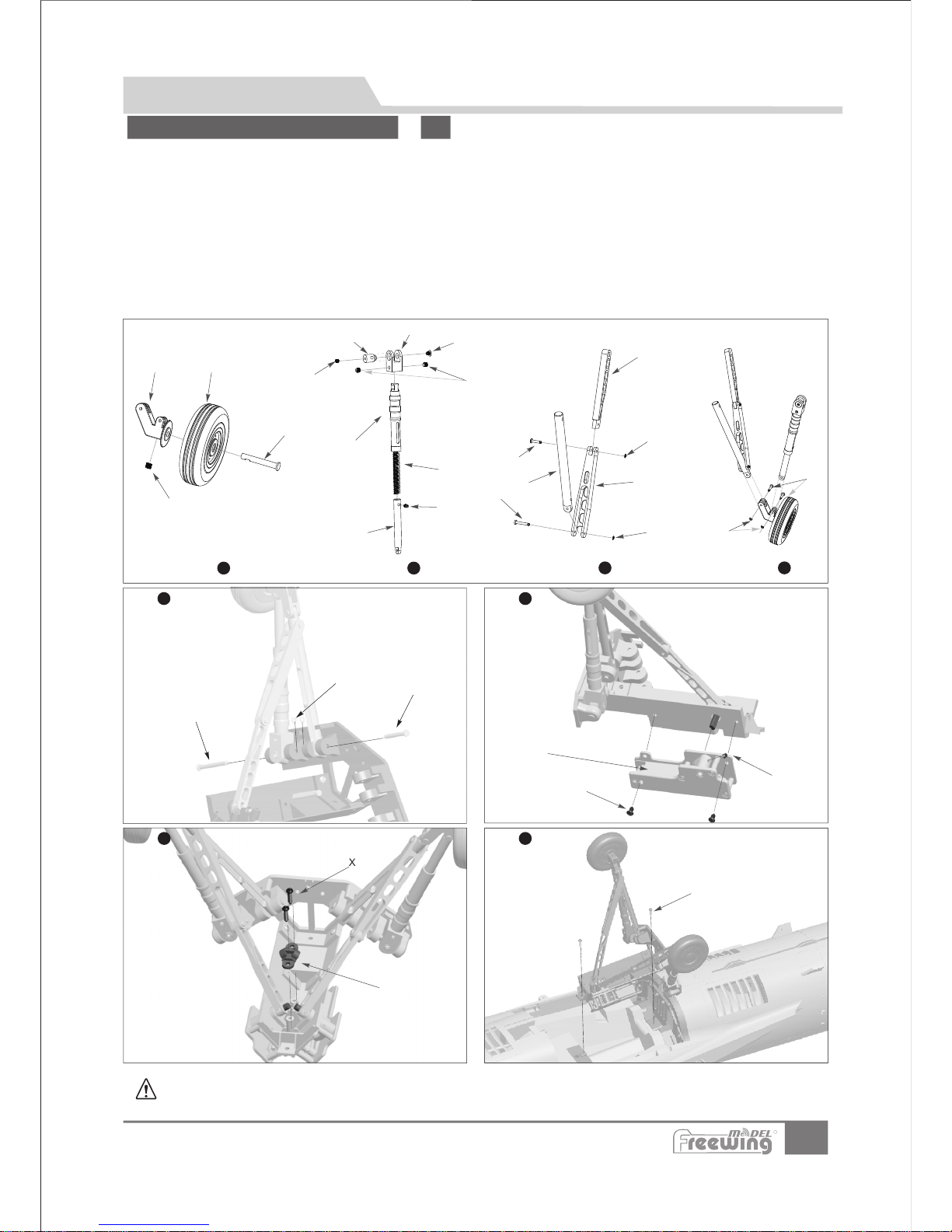
Please assemble and disassemble the rear landing gear by referring to the following photos.
W
X
M
X
X
Y
T
U
V
A
B
C
L
D
E
F
G
H
M
N
O
R
S
I
J
K
L
P
Q
S
S
1
2
3
4
5
6
7 8
Landing gear Assembly
EN
Rear Landing Gear Assembly
Accessories n am e and specifica ti on
Rear ge ar shock ab sorbe r conne cting arm
Rotat ing shaft
Rotat ing sleev e
Wheel
Rear ge ar axle
Rear ge ar main sup porti ng rod
Rear landing gear damping lever Rear
gear folding strut 1
( )
(Ø6.5x 24mm)
Ø60x1 6mm
A B CDE F G-
Springs(2pcs)
HI -
J K L MN OP QR-
Rear ge ar strut 3
Rear ge ar foldin g strut 2
Grub screws
Grub screws
Screws
Grub screws
Pins
Pins
Pins
(M4×3m m 6pcs)
(M3×3m m 4pcs)
(PWA 3×4mm 2 pcs)
(M3×5m m 2pcs)
(2pcs )
(2pcs )
(4pcs )
E-clips
E-clips
Pins
Pins
(Ø1. 5mm 8pc s)
(Ø2. 0mm 4pc s)
(2pcs )
(2pcs )
Electric retract
Screws(PWA3×12mm 2pcs)
Rear gear drive rod cover
S T U V WX Y -
Step
Step
Step
Step
Step
Step
StepStep
R
Page 10
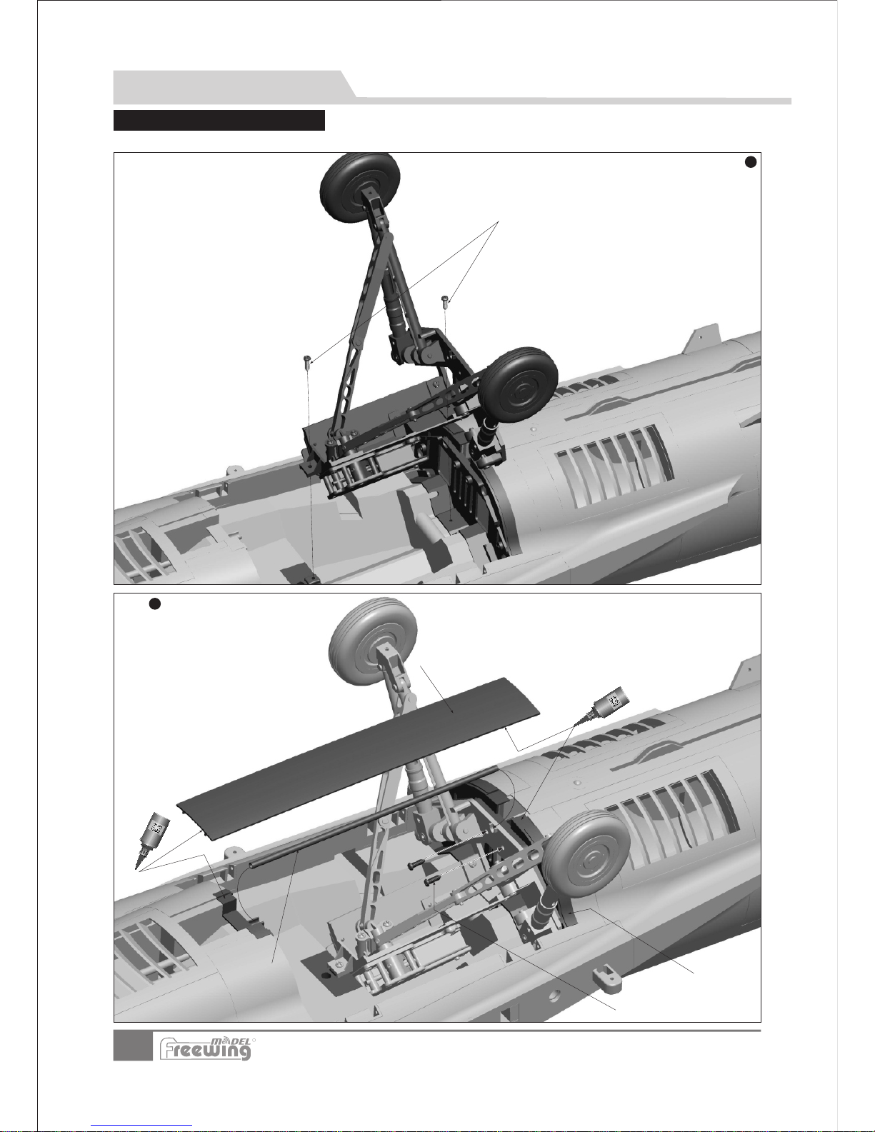
9
Item N o.:FJ310
F-104S Starfighter
A-
CD-
Screws(s(PPWWAA33xx8 28 2ppccss))
(Ø4x183.6mm)
B-Carbon rod
Rear gear mount
Plastic Fuselage cover
1
2
Screws(PWA3x12 2pcs)
A
B
C
D
Please assemble and disassemble the rear landing gear by referring to the following photos.
Landing gear Installation
EN
Main Landing Gear Assembly
Step
Step
R
Page 11
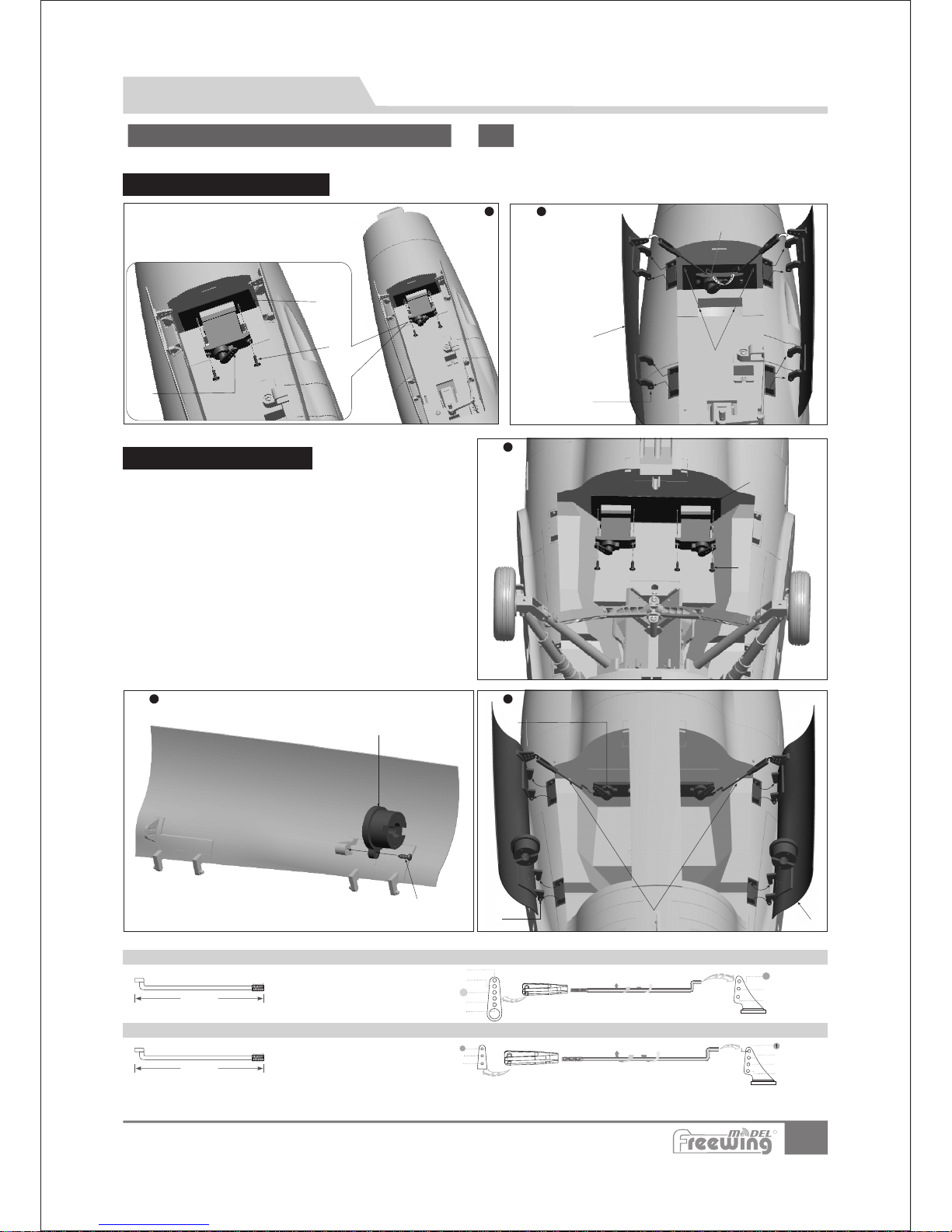
41. 5mm
(1. 63 in)
10
Item N o.:FJ310
F-104S Starfighter
Gear Door Installation
EN
Nose and main gear
door Installation
Assemble, disassemble and replace the nose/rear landing gear doors by referring to the following photos.
Nose Gear Door Installation
A-17g servo
BC-Screws
Servo hard point.
(PWA 2x 8mm 2pcs)
A
B
C
1
2
Step
Step
C
D
B
A
A-Screws
B-Servo hard point.
C-LED light
D-Screw
EFGH-Servo
(PWA 2x 8mm 2pcs)
(PA2x8mm 1pc)
Gear Door rotating shaft
Rear Gear Door (left/right)
Gear Door pushrod
A
B
1
Step
Main Gear Doors
C
D
G
F
H
E
2
Step
3
Step
2
3
4
1
2
3
1
2
3
4
5
2
3
1
33m m
(1. 3 in)
Rot ating p ushro d,can i ncrea se
or re duce co ntrol d istan ce.
R
Pus hrod di amete r:Ø1 .2m m
Pus hrod di amete r:Ø1 .2m m
Nose ca bin d oor p ushrod siz e
Rear ca bin d oor p ushrod siz e(2 pcs )
Servo p ush rod i nstallin g hol e
Servo p ush rod i nstallin g hol e(2 pcs)
A- Gear door rotating shaft
B- Nose Gear Door (left/right)
C- Servo
Page 12
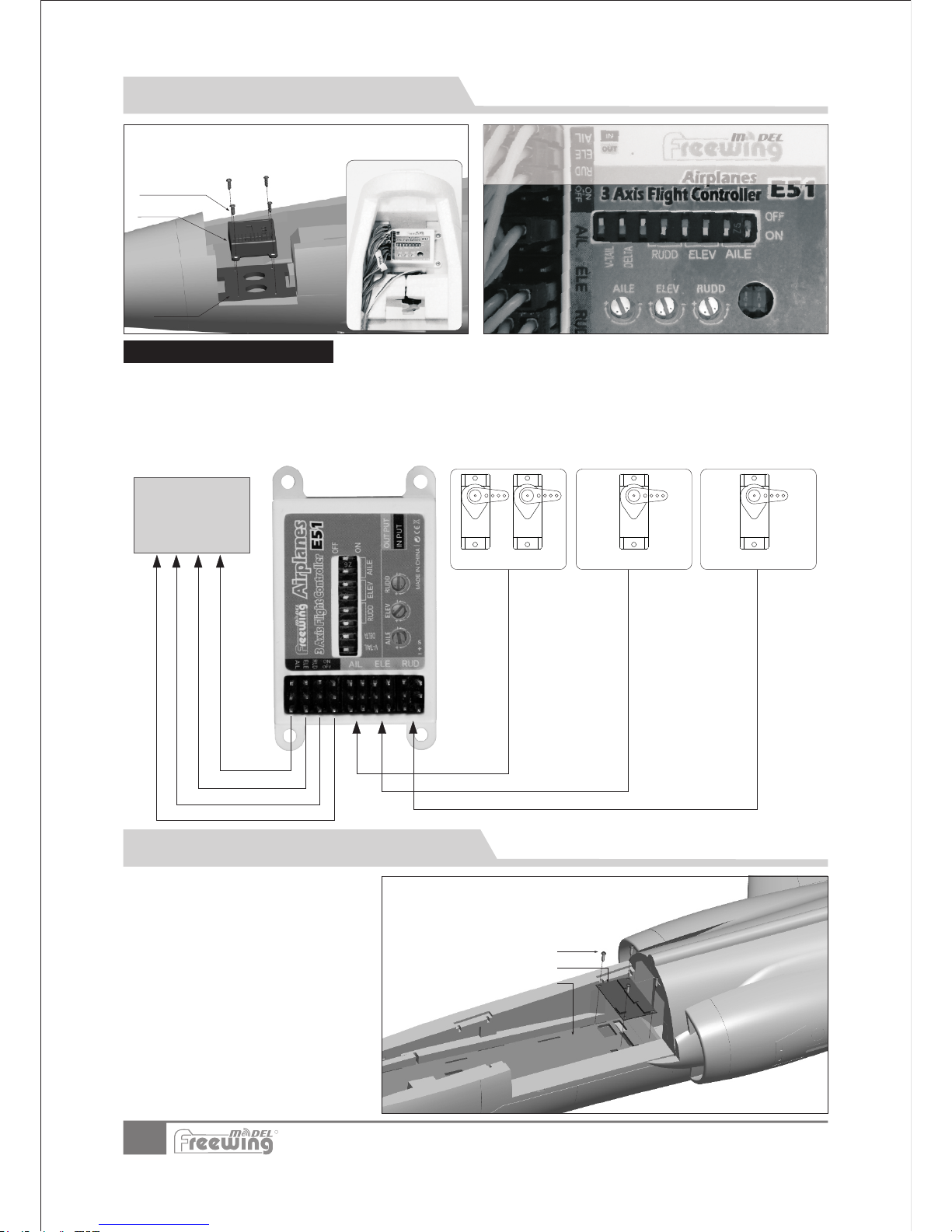
3-Axis Gyro use introduction
EN
11
Item N o.:FJ310
F-104S Starfighter
The F104 control board has two functions:
Control the function of the LED lights and gear doors
Reduce cable clutter in battery compartment.
1. .
2.
A
B
C
A-Screws
BC-
(PA3x 8mm 4 pcs)
Control board
Control board mount
Gyro
Screws
(PA2 .3x 8 4pc s)
Fix board
AIL ser vo
1.
2.
3.
4.
5.
Ensure the gyro is installed correctly.
Connect the servo cables of the elevator, rudder and ailerons to the Gyro output port.
Use 3 connection wires to connect the gyro input port to the corresponding channels of the receiver.
If your receiver has enough channels, you can use another connection wire to connect gyro and receiver and assign
an off/on gyro switch.。
For the Gyro use introduction,
please refer to the Gyro user manual.
ELE servo
RUD servo
Use 4 screws to secure the gyro to the board at the front of battery
compartment. Make sure the gyro decal is facing toward the nose
cone when installed.
Gyro connect io n diagram
Receiver
Control Board Introduction and Use
R
This gyro was set up at the factory to default sensitivity.
You can make small adjustments according to flight
c
onditions. If you need to restore the gyro to the factory
default settings, refer to this photo for directions.
Refer to the channel assignments on the
Control Board. Connect the servo cables to
the Control Board with the exception of the
aileron, elevator and rudder which are
connected to the output of the gyro. After
all the connections are made and tested,
use the 4 screws to attach the control board
to the fuselage .
Page 13
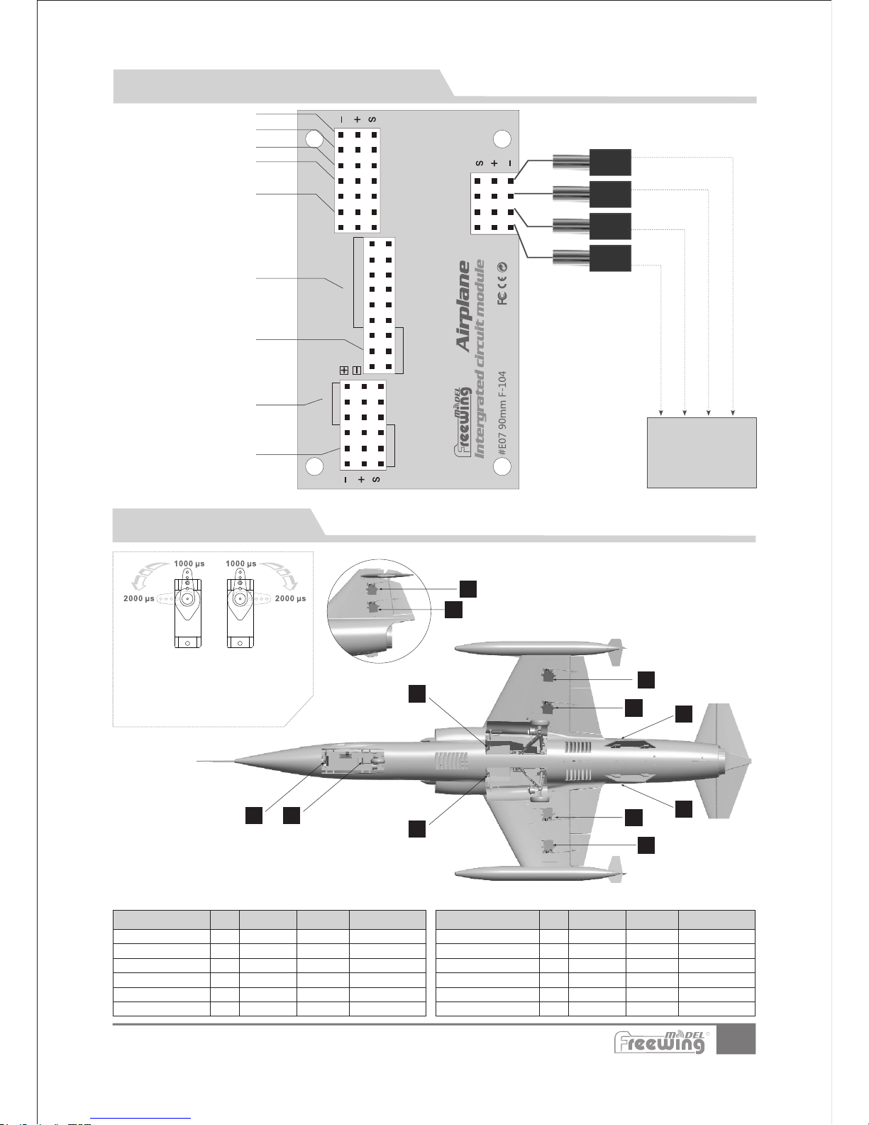
4
6
3
5
8
7
10
9
1
2
12
Item N o.:FJ310
F-104S Starfighter
12
11
Servo lntroduction
A servo or reversed servo is defined as follows:
When the servo input signal changes from 1000ųs to
2000ųs, if the servo arm rotates clockwise, it's a positive
servo. If it rotates counter clockwise, it's a reversed servo.
lf you choose to purchase another brand of servo,please refer to the following list to ensure that it is the correct size and type.
LED lig ht(Sing le flas hes)
Air-bra ke serv o
Throt tle (E SC)
Exter nal UBEC ac cess po rt
After burner ac cess po rt
Flap se rvo
Gear
Air -brak e
Air -brak e
Air -brak eAi r-b rak e
Air -brak e
FLA P
FLA P
FLA P
Landi ng L ight
Landi ng Gear
Cabin d oo r servo
Lan ding Li ght
Gea r
Aft erbur ner
UBE C cable
ESC t hrott le cabl e
Thr ottle
Cab in door
Receiver
Conne ct re cei ver air-brak e cha nne l
Conne ct re cei ver thrott le ch ann el
Conne ct re cei ver flap cha nne l
Conne ct re cei ver landin g gea r cha nnel
Control Board Introduction and Use
EN
1
2
3
4
5
6
9g-MG
17g-MG
17g-MG
17g-MG
17g-MG
17g-MG
No.
Pos./Rev.
400mm
150mm
180mm
180mm
120mm
120mm
Reverse
Positive
Positive
Positive
Positive
Reverse
lnstalling position
Nose gear door
Nose
gear steering
Aileron(L)
Aileron(R)
Flap(L)
Flap(R)
Servo cable length
Specific ation
650mm
650mm
250mm
250mm
400mm
360mm
No.
lnsta lli ng po sition
Pos./ Rev.
7
8
9
10
11
12
16g-MG
16g-MG
9g-MG
9g-MG
17g-MG
17g-MG
Reverse
Positive
Positive
Reverse
Positive
Positive
Servo cable length
A L)
Air-brake(R)
Elevator
Rudder
ir-brake(
Rear gear
door(L)
Rear gear
door(R)
Specific ation
speci al use
Str obe lig ht
Accor ding to t he no ted, con nect th e servo c abl e or LED li ght cab le to t he corr ect acc ess p ort.
R
Page 14
78mm
(3-1/8")
13
ESC
Item No .
KV
Value
Volate
(V)
Curre nt
(A)
Pull
(g)
Motor
Resis tance
Weigh t
(g)
No Load
Curre nt
Prope ller
155 0RPM/ V
22.2
95
3600
0.02
195
2.7A/ 10V
95A
90mm
Ducte d Fan
MO 0374 8
18 .4 5mm
12 .5 mm
M3.0 (4pcs)
54.29mm
47.29mm
20.35mm
36 .9 mm
6. 0m m
M3.0
Item N o.:FJ310
F-104S Starfighter
Lift up tape and remove the
battery compartment cover
EN
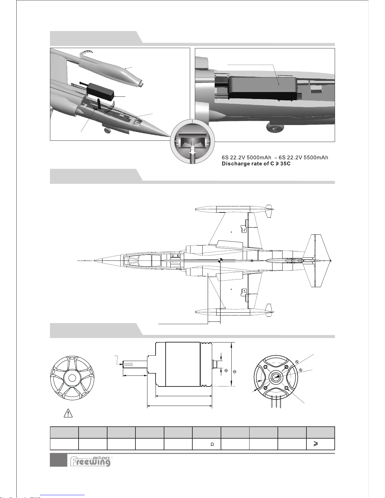
Battery Installation
Battery hatch space size: 60x27x10mm
Before connecting a battery to the ESC, please
switch on the transmitter power and make sure
the throttle stick is in the lowest position.
Engaged the kill switch if you have one
assigned.
Batte ry co mpa rtment cov er
Batte ry
Batte ry tr ay
Velcro
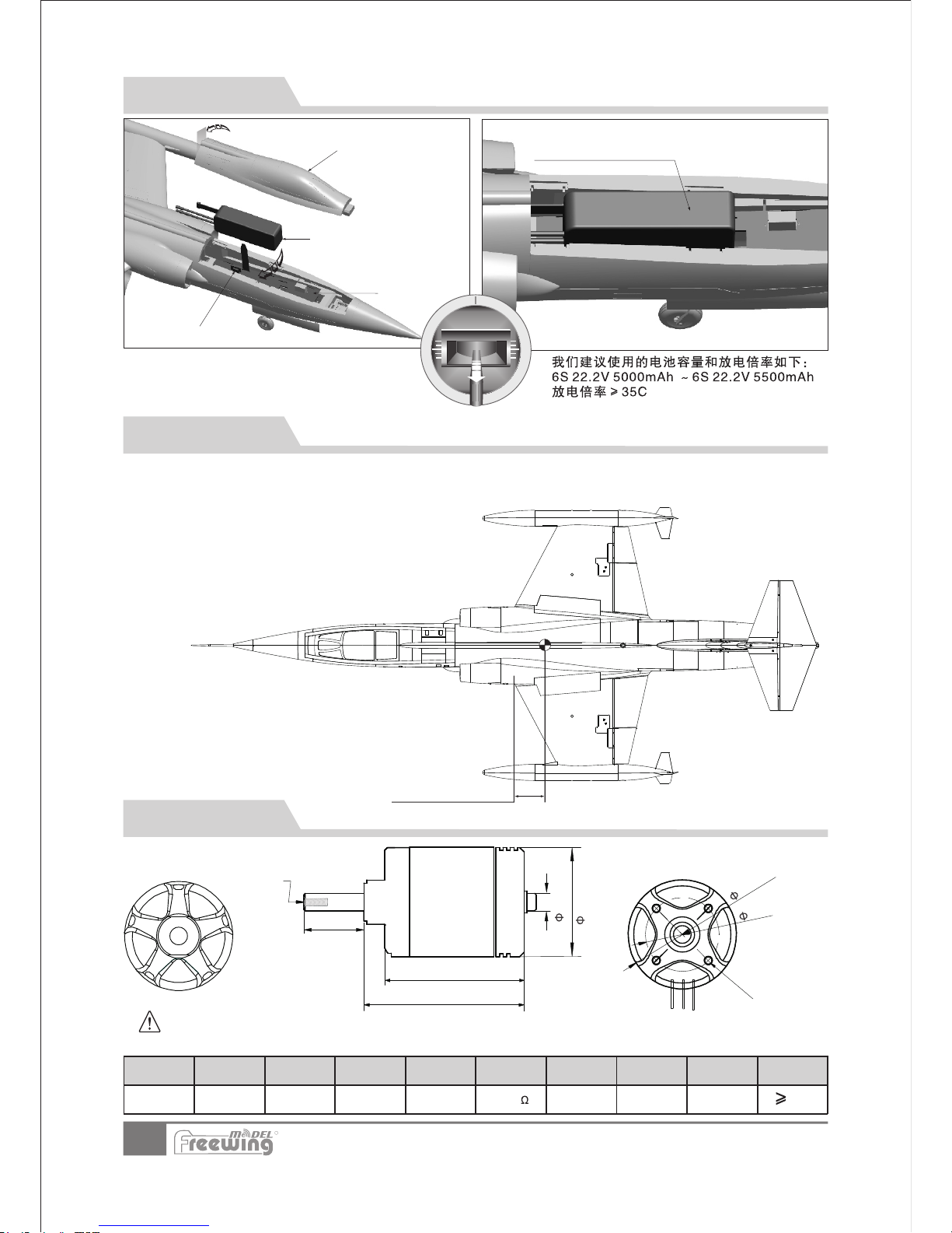
Center of Gravity
After installing the battery, use
the Velcro strap to lock it in.
NOTE:This motor is a special product for use only with the Freewing 90mm 12-blade ducted fan P090
2.
Conversely, the 90mm 12-blade ducted fan P0902 is not for use with any other motors!
Motor parameters
R
The recommended battery capacity and discharge
rate is:
The correct Center of Gravity is directly related to the
success of the initial flights. Refer to the following
diagram to ensure you have the proper CG. Once
comfortable with the airplane, you can adjust the CG to
suit your individual taste.
You can adjust the CG by moving the
battery either forward or back. If you find
that moving the battery is insufficient,
you can use some other suitable material
such as a sticky back weight strip to
counter weight.
Page 15
EN
14
Item N o.:FJ310
F-104S Starfighter
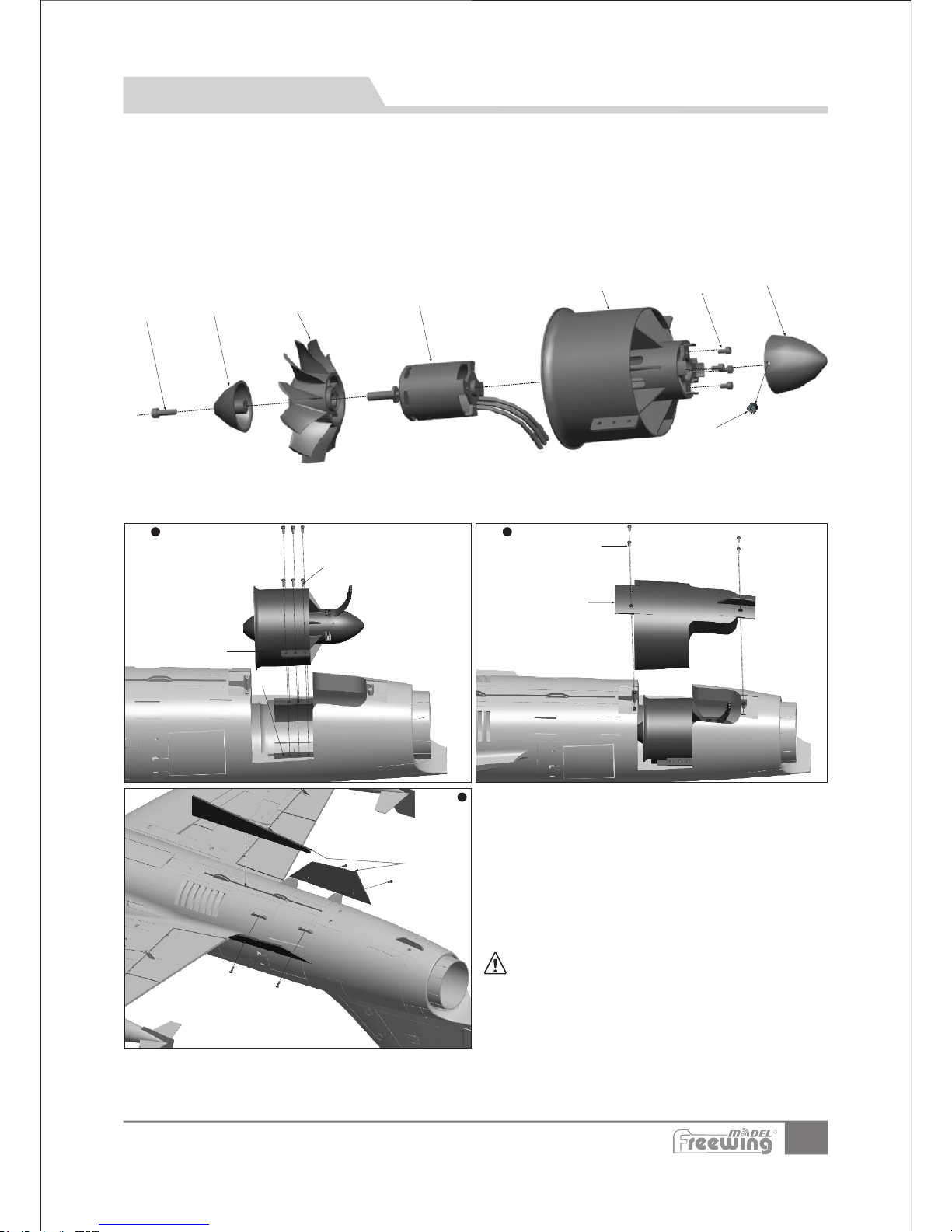
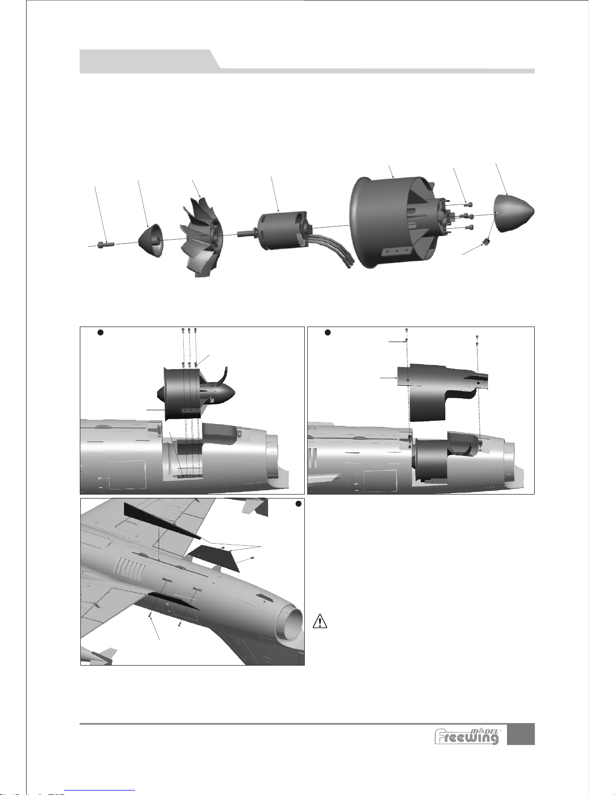
1.Place the“motor(D)”into the“ducted fan housing(C) ”.
2.Attach the motor with 4“cup head screws(B)”.
3.Put the“rotor(E)”in the motor shaft.
(During this process,please note the hardware platform of rotor should be aligned with the motor shaft platform)
4.Use“spinner(F)”to cover the rotor,and lock it in place with “cup-head-screw(G)”.
5.Attach the“tail fan cowl(A)”to the bottom of “ducted fan housing(C)” and lock it in place with 2 “Grub screws(H)”.
A
B
C
D
E
F
G
H
HM 4x14
M3x3
Hm3x8
M
L
I
J
k
N
1
Step
2
Step
3
Step
Power System Installation
Accessories n am e and specifica ti on
Note:When ESC and battery connected, do
not touch them by hand to avoid accidental injury.
When testing EDF, please use a safety test stand and
again, do not touch the unit!
EDF pow er system
Screws
Screws
Fan cov er
Screws
(
(PA3x8 mm 4pcs )
(PA3x8 mm 4pcs )
PWA 3x12m m 6pcs)
Fusel age
Fin
I J K L MN -
O-
R
Page 16
EN
Control direction test
15
Item N o.:FJ310
F-104S Starfighter
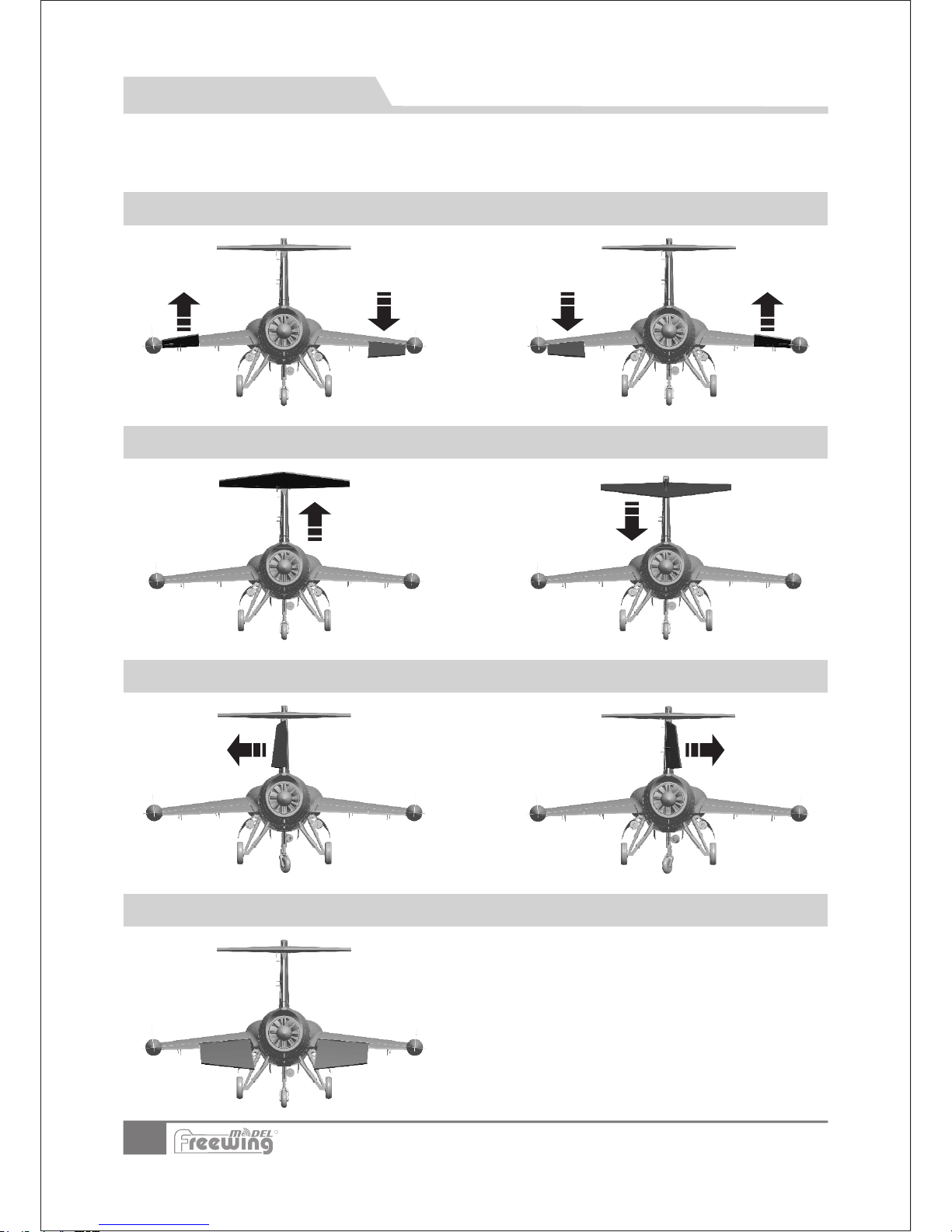
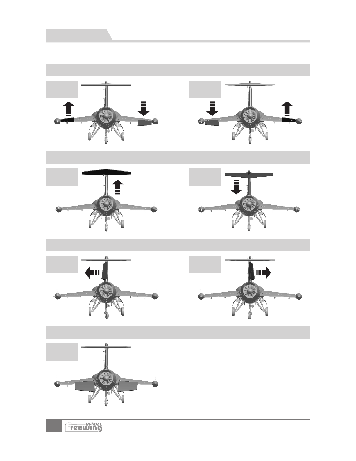
After the build is complete, power up the radio and connect a fully charged battery to the ESC. Use
the radio to ensure correct control direction.
Ailerons
Elevator
Rudder
Flaps
Stick Left
Stick Right
Stick Back Stick Forward
Stick Left Stick Right
Flaps down
R
Page 17
16
H1
H2
H1
H1
H2
H1
H2
Item N o.:FJ310
F-104S Starfighter
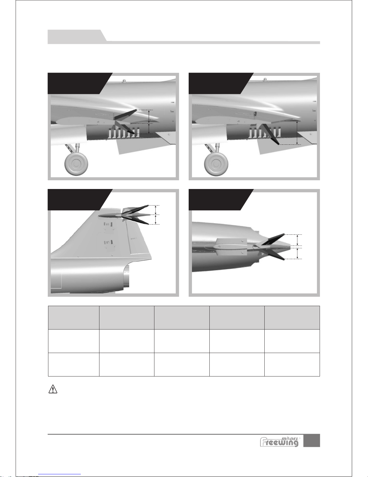
According to our test results, the following rates proved to be a good starting point. Low rates are good for initial flights or
less experienced pilots. High Rates will be more sensitive to control inputs After initial flights, adjust the rates to suit
your own style.
EN
Dual Rates
Ailerons
Flaps
Elevator Rudder
Flaps
RudderElevator
Ailerons
Low Rate
H1/H2 20mm/20mm
D/R Rate:80%
H1/H2 35mm/35mm
D/R Rate:80%
H1/H2 22mm/22mm
D/R Rate:75%
H1 27mm
High Rate
H1/H2 25mm/25mm
D/R Rate:100%
H1/H2 43mm/43mm
D/R Rate:100%
H1/H2 27mm/27mm
D/R Rate:100%
H1 41mm
Flight note:when flaps are deployed, the nose will drop, to counter this, set up 6% elevator mix to
balance the airplane in half flap rate. Set a 12% elevator up mix to balance when in full flap rate.
R
Page 18
17
注意:模型 产品是 具一定 危险性 的产品,请禁止14岁以下的儿童玩耍,1 4 岁以上 的儿童 ,请在 有飞行 经验的 成人指 导下使 用,无 飞行经 验的购 买者, 应当在 具有
一定电动涵道 飞机飞 行经验 的成人 指导下 使用! 组 装模型 前,请 仔细阅 读说明 书,按 照说明 书的要 求进行 安装. 进行调试和飞行时,请根据说明书 指示的 参数进 行调整 。
前 言
中文版
重 要 提 示
1.模型飞机不是玩具,操作者需要具备一定的经验;没有经验的初学者,必须在有丰富经验的专业人士指引 下,逐步 学习!
2.在组装之前,必须认真阅读产品说明书,严格按照说明书指示操作。
3.飞翼模型及其销售商,对于违反说明书的要求操作而造成的损失、将不负任何法律责任!
4.模型飞机的使用年龄必须是14岁以上的儿童或者成人。
5.此模型产品使用EPO材料制成,表面喷涂油漆,不可随意使用化学制剂擦拭,否则会损坏模型产品 。
6.不可以在公共场合、高压线密集区、高速公路附近、机场附近或者其它法律法规明确禁止飞行的 场合 飞行 。
7.不可以在雷雨、大风、大雪或者其它恶劣气象环境下飞行。
8.模型飞机的电池产品,不可以随意乱扔,乱放。存放时,必须保证周边2M范围内,无易燃、易爆物体。
9.损坏或者报废处理的模型飞机电池,应妥善回收处理,不准随意抛弃,避免自燃而引发火灾。
10.在飞场飞行时,应做到妥善处理飞行后所产生的垃圾,不可随意抛弃、焚毁模型及其配件。
11.在任何情况下,都必须保证油门杆处于起始位、发射机处于打开状态时,才能连接模型飞机内 部的 动力 电池.
12.无论是模型飞机是在正常飞行过程中,或者是在缓慢降落过程中,都不要尝试用手去回收模型。必 须等 模型 降落停
稳以后 ,再进行回收!
目 录
前言
产品基本参数
产品包装清单
机体组装
机头组装
减速板安装
起落架组装
舱门组装
陀螺仪使用介绍
17
18
18
19
22
22
23
26
27
集线板使用介绍
舵机使用介绍
电池安装说明
重心示意图
电机参数
动力系统的安装
舵面测试
大、小舵参数
27
28
29
29
29
30
31
32
Item N o.:FJ310
F-104S Starfighter
F-104“Starfighter”是 美 国 洛克 希 德 .马 丁公 司 研 制的 超 音 速轻 型 战 斗 机 。 1951年 开 始 设计 ,
1958年 开始装备 部队。各 种型号共 计生产了2,578架, 使用国家/地区 达15个,成 为60年代和 米格-21、幻
影III 齐名的世界三大标准战斗机之一。 该机也是第一种实用的M2 一级战斗机,还是第一种曾经同时保持世
界高度和速度纪录的飞机。
由Sebart与Freewing联合制作 的90mm F-104S“Starfighter ”电 动EPO材料模 型 , 翼展和机长分别
为755mm/1720mm,采用 了二种不 同风格的 涂装,分 别 是隶属于 乔治空军 基地的第479战术 战 斗机联队
的FG-907银色涂装和黄、黑相间的意大利空军82周年纪念涂装。
这款90mm F-104S“Starfighter”电动 模型的整体 外形,在尽 可能符合真 实飞机的前 提下,我们 对主
翼、平 尾的形 状和面积 做了一些 细微调整,让产 品的飞行 品质变得 更加稳 定一些。 尾喷火焰 灯、机体警示
灯、着陆灯的运用,使得模型在飞行过程中,更加逼真。电动涡杆控制的铝合金减震起落架,能够有效吸引
降落时的冲击力。由玻璃钢材料制作的前、后舱门,在减轻重量的同时,减少了飞行过程中的阻力。特殊设
计的空气减速板,一方面,能够在高速飞行时,给电动涵道动力组带来更多的进气量;另外一方面,在降落
时展开,使降落速度更慢一些。除此之外,我们为这款模型设计了飞行员、仪表 贴纸、皮托管等丰富细节。
这款 模型采用了 螺丝固定的 可拆卸结构 设计,主翼 、平尾、垂 尾均可以快 速拆装。其 中,主翼、 平尾和
垂尾 内部,均嵌入了大量的碳 纤管进行加强。除 此之外,通过特殊 的加固方式,保证了T型尾翼的工作 可靠
性。PNP配置预装了2颗16g金属数 字舵机、7颗17g金属 舵机和3颗9g金 属舵机, 使用球 头连接。 内置12叶
涵道风扇组和3748-1550KV无刷外转马 达,配 合HOBBYWING订制的130A(8A UBEC)电调, 带来优 秀
的气流声效和强大的推力。通过集线板功能,使电池舱更加整洁。
90mm F-104S“Starfighter”电动 模型内置 了Freewing的E51陀螺仪, 进 一步强化 飞行稳定 性。模
型在飞行过程中,拥有出色 的速度 和爬升 性能, 能够轻 松应对常规的仿真战术飞行动 作。由 于F104的特 殊
气动外形,我们需要较长的下滑道,配合空气减速板,以大约30度左右的仰角减速 降落。
R
Page 19
18
产 品 基 本 参 数
中文版
打开产品包装,核对包装清单。(不同 配置的版本,包含内容不 同)
序号
配件名称
PNP
KIT Plus
Airfr ame
产 品 包 装 清 单
序号
配件名称
PNP
KIT Plus
Airfr ame
Item N o.:FJ310
F-104S Starfighter
1
2
3
4
5
机身套件
主翼套件
平尾套件
垂尾套件
机头
6
7
8
9
10
副油箱
五金配件
碳纤管
胶水/贴纸
说明书
注意:此处 各项 参数 ,均 使用 本公司 配件 测试 得出 ,如果 使用 副厂 配件,
会有 所差 异。使 用副 厂配 件时 所产生 的问 题, 我们将 无法 给予 技术 支持!
R
1720mm(67.7in.)
755mm(29.73 in.)
起飞重量:2800g (不含电池)
推力:3150g
涵道:12叶 90mm涵道
电机:3748-1550KV无刷外转电机
电调:130A 电调 带8A UBEC
舵机:9克舵机x3,16克舵机x2,17克舵机x7
7通发射机和接收机
6S 5000mAh-6000mAh 锂电池
锂电池充电器
产品基本参数
飞行所需其他配件
Page 20
机 身 组 装
主翼
主翼 舵 机安 装
机 体 安 装
中文版
19
使用胶水、碳纤管粘合前、后段机体。
碳纤管规格:Ø6x180mm 2pc s
注:包装盒 内有赠送的E PO胶水,请 使
用这支 赠送的胶水 进行粘合作 业。涂
摸胶水 应该均匀。 胶水均匀涂 摸完毕,
不要立 即粘合,请 等待90秒时间 ,再
进行粘 合,效果最 佳!
主 翼 安 装
1.通过舵机测试仪或者遥控器,把舵机摇
臂校正到居中位置;
2.用胶水把17g舵机盒(C)和舵机面摇臂(D)
粘在主翼上;
3.把舵机安装到17g舵机盒(C)内,同时把
舵机线压入舵机线槽(F),然后盖上17g
舵机盖(B),最后用2颗螺丝(A)锁紧固定
舵机;
4.用舵机传动控制钢丝(E)连接舵机摇臂与
舵面摇臂(D)。
1.把舵机线与机身延长线连接起来;
2.然后将主翼插入机身;
3.拧入4颗螺丝固定主翼
A
B
C
ABCDEF-
螺丝
副油箱
主翼
碳纤管
舵机、LED灯延长线
螺丝
(
(Ø )
(PM3x14mm 4pcs)
PA3x 8mm 4 pcs )
8x300 mm
步骤
1
步骤
2
D
E
Item N o.:FJ310
F-104S Starfighter
步骤
3
F
A
B
舵机
D
E
C
F
A B CD-
EF-
螺丝
17g舵机盖
17g舵机盒
舵面摇臂
主翼舵机控制钢丝
舵机线槽
(PWA2x 8mm 4 pcs )
将碳纤管安 装在线槽里面,使用胶水粘 贴即可;
碳纤管规格: Ø4x10 0mm 2pc s
步骤
1
步骤
1
R
Page 21
机 体 安 装
中文版
20
Item N o.:FJ310
F-104S Starfighter
ABCDEF -
螺丝
17g舵 机盖
17g舵 机盒
舵面摇臂
垂尾舵机控制 钢丝
舵机线槽
(PWA 2x8 mm 4p cs)
平尾、垂 尾 舵 机 安 装
平尾、垂尾
平尾舵机钢 丝安装孔位
平尾控制钢 丝尺寸
钢丝直径 Ø1. 5mm
58m m
(2. 28 in)
1
2
3
4
5
1
2
3
垂尾舵机钢 丝安装孔位
垂尾控制钢 丝尺寸
钢丝直径 Ø1. 5mm
80m m
(3. 15 in)
1
2
3
4
5
1
2
3
1
2
4
5
钢丝直径 Ø1. 5mm
70m m
(-2/3")2
襟翼控制钢 丝尺寸 襟翼舵机钢丝 安装孔位
2
3
1
2
3
4
5
钢丝直径 Ø1. 5mm
70m m
(2-2/3")
副翼控制钢 丝尺寸 副翼舵机钢丝 安装孔位
2
3
1.通过舵机测试仪或者遥控器,把舵机摇臂校正到居中位置;
2.用胶水把17g舵机盒(C)和舵机面摇臂(D)粘在平尾、垂尾上;
3.把舵机安装到17g舵机盒(C)内,同时把舵机线压入舵机线槽(F),然后盖上17g舵机盖(B),最 后用2颗 螺丝( A)
锁紧固定舵机;
4.用舵机传动控制钢丝(E)连接舵机摇臂与舵面摇臂(D)。
A
B
舵机
C
E
D
F
3
R
Page 22
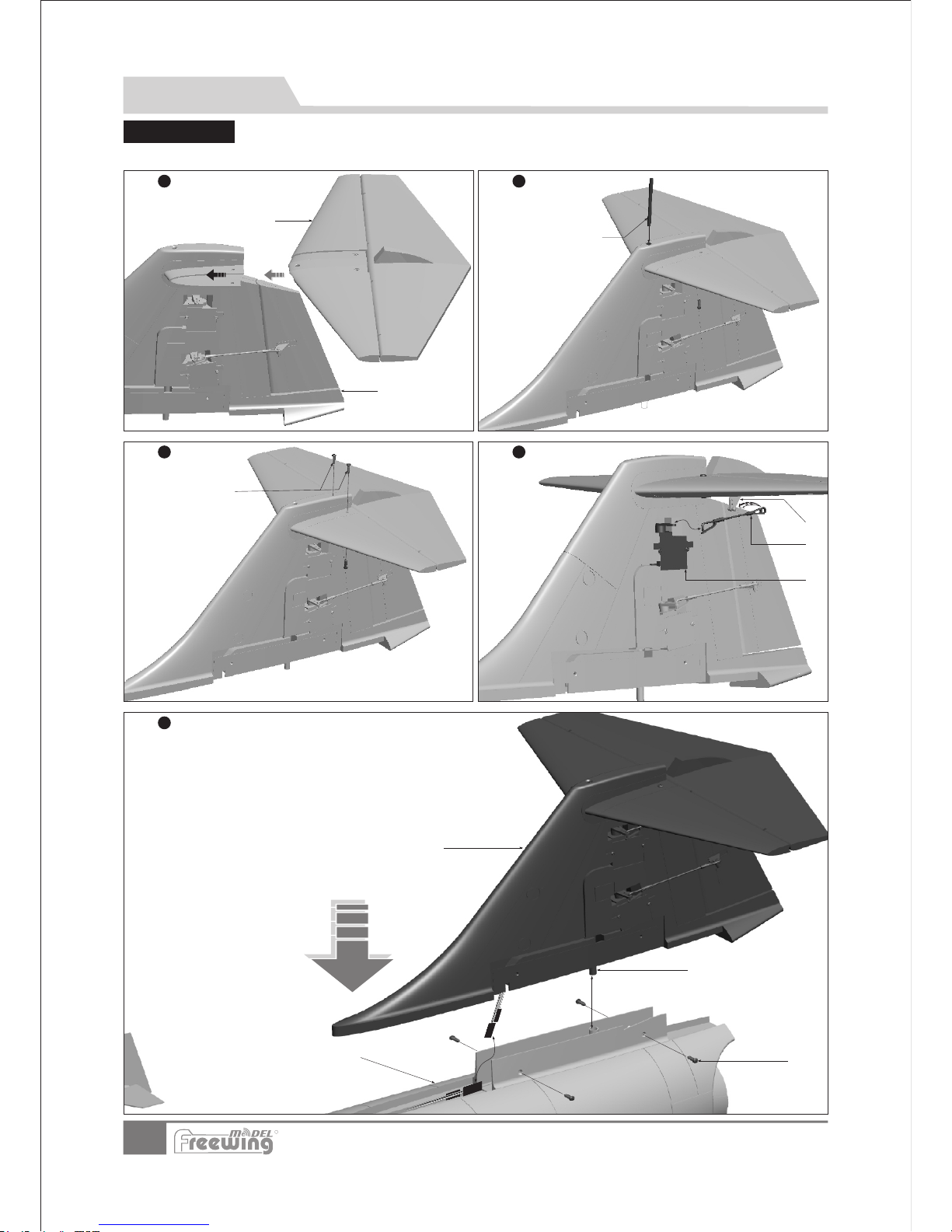
21
Item N o.:FJ310
F-104S Starfighter
机 体 安 装
中文版
尾 翼 安 装
ABCD-
碳纤管
螺丝
机身尾部
垂尾
(FA3x8 4pcs)
请参考以下图示,安装尾翼!
A
B
AB-
平尾
垂尾
碳纤管(Ø 4x2 00m m)
步骤
1
A
B
C
螺丝(FWA3 x8 4p cs)
A B -
C-
舵面摇臂
平尾舵机控 制钢丝
平尾舵机
步骤
2
步骤
4
步骤
3
步骤
5
A
B
C
D
R
Page 23
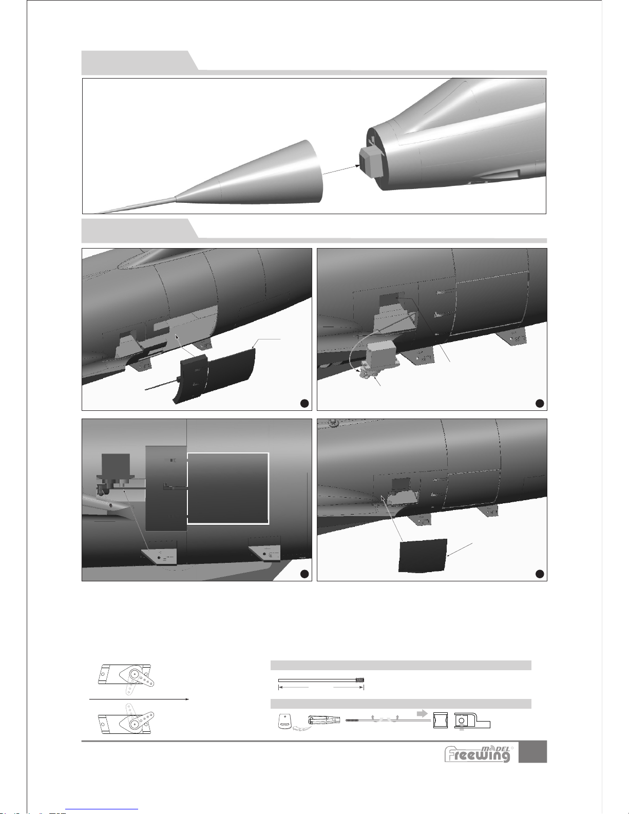
磁吸附
22
Item N o.:FJ310
F-104S Starfighter
机 头 组 装
中文版
减 速 板 安 装
由于采用磁力吸附结构,我们只需要装机头罩吸在机头前端即可。
步骤
1
A
步骤
2
B
C
步骤
3
步骤
4
E
1.通过舵机测试仪或者遥 控器,把舵机摇臂
校正到运动起始位置;
钢丝直径 Ø1. 5mm
( 1.9 7in)
50m m
减速板控制 钢丝尺寸
减速板舵机 钢丝安装孔位
旋转钢 丝,可以增加或 者减少
控制距 离
2.使用胶水将减速板套件 (A)粘到机体二侧。
3.用胶水将舵机(B)粘到舵 机安装座(C)处。安装时过程中 ,请注意:
-将舵机线与机身内置延长 线连接并固定好
-将传动钢丝插入舵机摇臂 上的固定栓内。
4.保持减速板处于正确的 闭合位置时,锁紧固定栓上的 螺丝 。
5.测试功能正常后,用胶 水粘合舵机盖,保护舵机!
减速板套件
16g舵机
舵机安装座
ABC-
舵机盖
舵机控制钢丝
DE-
往机头方向
R
Page 24
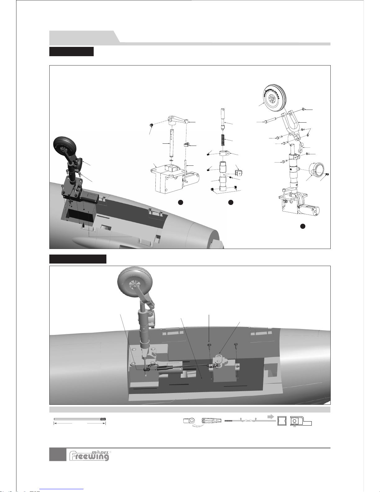
23
Item N o.:FJ310
F-104S Starfighter
起 落 架 组 装
中文版
前起落架 组 装
前起落架 舵 机 安 装
A
B
D
C
ABCD-
螺丝
舵机
舵机控制钢丝
起落架固定座
(PMA2x8mm 2pc s)
起落架转向 控制钢丝尺寸
转向舵机钢 丝安装孔位
旋转钢丝,可以增加或者减少
控制距离
钢丝 直 径 Ø1. 5mm
( 3.7 8in)
96m m
请参考以下图示,组装、更换、维修前起落架;
配件名称及 规格参数
A B CDE F GHI -
起落架收放控制器
前起落架转向钢丝
前起落架转向控制 环
前起落架主钢丝
L型摇臂
机米螺丝
机米螺丝
前起落架主撑杆
螺丝
(M3×3mm 1pcs)
(M4×4mm 2pcs)
(PM2x3mm 1pcs)
J K L MN OP QR -
螺丝
LED灯安装臂
U型减震臂
螺丝
弹簧
减震活动杆
螺丝
LED灯
梢钉
(PM2x4mm)
(PM2x3mm)
(PA2 x8m m)
(Ø3.5x9. 2mm )
S T U V WX -
-
E型扣
8字型减震转轴
梢钉
U型斜撑杆
轮轴
E型扣
机轮
(内径Ø1.5mm)
(Ø3.5x11 .3m m)
(Ø5x25.5 mm)
(内径Ø2mm)
(Ø45x16m m)
前起落架组件
螺丝(PWA3x12 4pcs)
前起落架安装座
G
H
I
K
J
M
L
N
O
步骤
2
PQ
R
S
T
R1
S1
U
V
X
W
AB
步骤
3
A
B
C
D
E
步骤
1
F
AB
R
Page 25
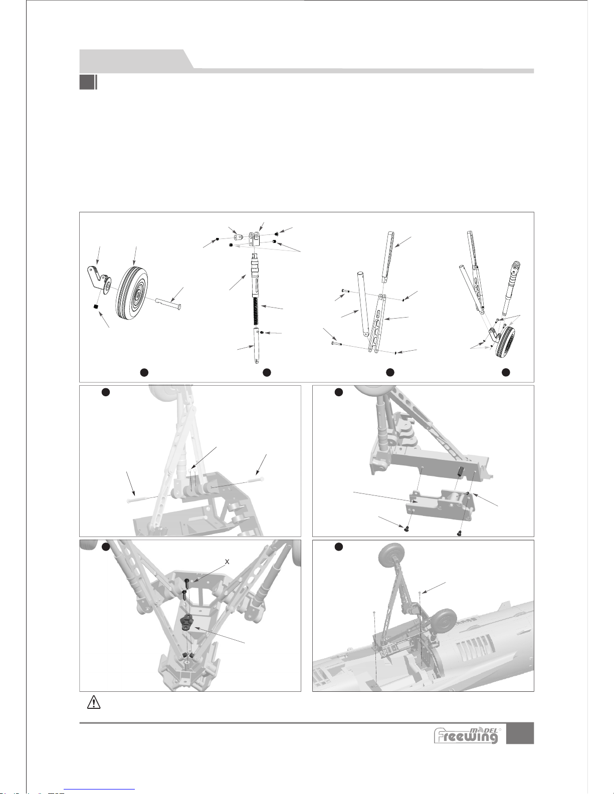
24
Item N o.:FJ310
F-104S Starfighter
注意:在整个起 落架组装过程中,所 有带扁口的零件 ,在用螺丝固定时, 扁口面必须面向 螺丝孔,只有这样,螺丝的固定
才是有效的,零 件才能不会转动和脱 落。
起 落 架 组 装
中文版
请参与以下图示,组装,更换、维修后起落架;
配件名称及规格参数
AB C DE F GHI -
后轮减震连接臂
机轮
后轮轮轴
旋转轴
旋转轴套
后起落架主撑杆
弹簧
后起落架减震活 动杆
后起落架折叠支 撑杆1
(M3×3m m 3pcs)
(2pcs)
J K L MN O P Q R -
后起落架支撑杆3
后起落架折叠支 撑杆2
机米螺丝
机米螺丝
螺丝
机米螺丝
梢钉
梢钉
梢钉
(M4×3m m 6pcs)
(M3×3m m 4pcs)
(PM3×4 mm 2pcs)
(M3×5m m 2pcs)
(2pcs )
(2pcs )
(4pcs )
S T U V WX Y -
E型扣
E型扣
梢钉
梢钉
起落架收放控制 器
螺丝
后起落架传动杆 固定盖
(Ø1.5 mm 8p cs)
(Ø2.0 mm 4p cs)
(2pcs )
(2pcs )
(PWA 3×1 2mm 2 pcs)
后起落架组装
W
X
M
X
X
Y
T
U
V
A
B
C
L
D
E
F
G
H
M
N
O
R
S
I
J
K
L
P
Q
S
S
步骤
1
步骤
2
步骤
3
步骤
4
步骤
5
步骤
6
步骤
7
步骤
8
R
Page 26
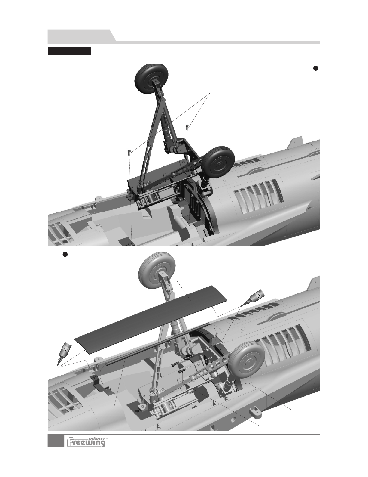
25
Item N o.:FJ310
F-104S Starfighter
后起落架 组 装
请参考以下图示,组装、更换、维修后起落架;
ABC-
D-
螺丝
碳纤管
后起落架固定板
机身塑料盖
(PWA 3x8 2pcs)
( 4 x18 3.6 mm)Ø
起 落 架 组 装
中文版
步骤
1
步骤
2
螺丝(PWA3x12 2pcs)
A
B
C
D
R
Page 27
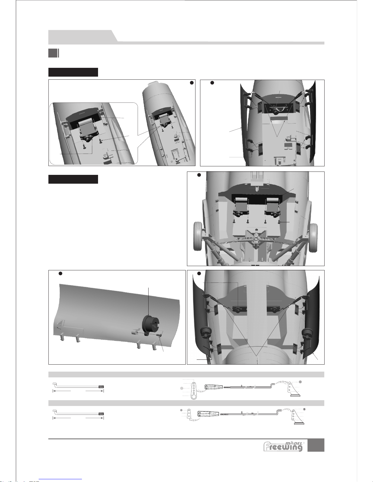
26
Item N o.:FJ310
F-104S Starfighter
钢丝直径 Ø1. 2mm
41. 5mm
(1. 63 in)
2
3
4
1
2
3
旋转钢 丝,可以增加
或者减 少控制距离
后舱门控制 钢丝尺寸(2pcs ) 后舱门 (2pcs )舵机钢丝安 装孔位
前舱门舵 机 安 装
后舱门舵 机 安 装
A B CD-
EF GH-
螺丝
舵机安装座
LED灯
螺丝
后起落架舱门(左右)
舱门控制钢丝
舵机
(PWA 2x 8mm 2pcs)
(PA2x8m m 1pcs)
舱门旋转轴
舱 门 组 装
中文版
前、后舱门安装
A
B
步骤
1
步骤
2
步骤
3
请根据以下图示组装、拆解、更换前、后起落架舱门配件;
ABC-
17g舵机
舵机安装座
螺丝(PWA2x 8mm 2pcs)
A
B
C
ABCD-
舱门旋转轴
舵机
前起落架舱门(左右)
舱门控制钢丝
C
D
步骤
1
步骤
2
B
A
前舱门舵机 钢丝安装孔位前舱门控制 钢丝尺寸
钢丝直径 Ø1. 2mm
1
2
3
4
5
2
3
1
C
D
G
F
H
E
33m m
(1. 3 in)
R
Page 28
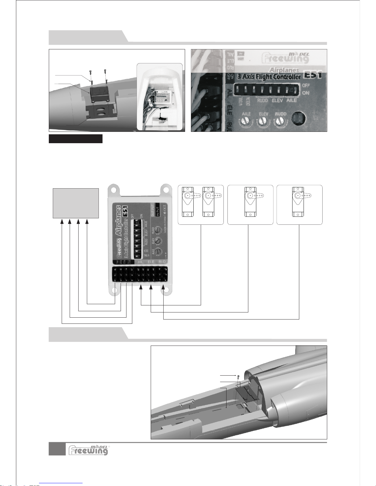
27
Item N o.:FJ310
F-104S Starfighter
中文版
集 线 板 使 用 说 明
F-104 集 线电路板有二个功 能:
1.控制LED灯 及舱门的正常工作 。
2.减少电池 舱内的线材数量。
A
B
C
陀 螺 仪 使 用 说 明
参考集线板 上的通道标识,将 所有电池舱 内的连 接
线插入集线 板。(不包含副翼 、升降舵、 方向舵 ,
此三个通道 直接接入陀螺仪)
接线工作完 成后,使用螺丝固 定集线板, 防止松 动。
ABC-
螺丝
集线板
集线板安装座
(PA3x 8mm 4 pcs)
用四颗螺丝将陀螺仪固定在电池舱最前端的固定板上。安装时,
确定陀螺仪贴纸上的LOGO朝机头方向!
陀螺仪
螺丝
(PA2 .3x 8mm 4 pcs )
固定板
副翼舵机 升降舵机 方向舵机
遥控 器
接收 机
1.请正确安放陀螺仪,
2.将平尾、方向及副翼舵机线分别接入陀螺仪输入端;
3.使用3根连接线,将陀螺仪输出端与接收机对应通道连接;
4.如果您的接收机通道数目充许,您可以再使用一根连接线连接陀螺仪与接收机,用来设置陀螺仪 开关 。
5.陀螺仪详细使用方法,请参考包装盒内的《陀螺仪使用说明书》。
陀 螺 仪 连 接 示 意 图
出厂时,陀螺仪 已经通过测试,并设 置好默认感度值 ,您可以
根据实际情况, 进行小幅度调整。
如果您需要恢复 到出厂默认感度值, 请参考此图。
R
Page 29
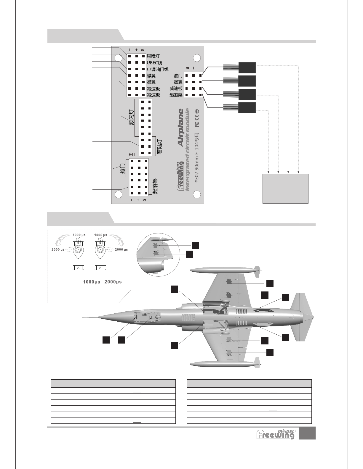
4
6
3
5
8
7
10
9
1
2
我们的舵机 正、反向标准是:
当舵机输入 信号从 到 时,
如果舵机摇 臂,
顺时针旋转- --正向舵机
逆时针旋转- --反向舵机
舵 机 使 用 介 绍
28
Item N o.:FJ310
F-104S Starfighter
中文版
如果您需要选购 其它品牌的舵机进行 安装,请参考下 面的表格选择正确的 舵机
集 线 板 使 用 说 明
12
11
根据注明,将舵机线 或者LED灯线插入 正确接口上
起落架
起落架舱门 舵机
LED灯(单 次闪烁)
减速板舵机
襟翼舵机
油门(电调 )
外置UBEC接 入端口
尾焰灯接入 端口
遥控 器
接收 机
接 入 接 收 机
接 入 接 收 机
接 入 接 收 机
着陆灯
序号
1
2
3
4
5
6
规格
9g-金属
17g-金属
17g-金属
17g-金属
17g-金属
17g-金属
正、反向
反向
正向
正向
正向
正向
反向
舵机线长
400mm
150mm
180mm
180mm
120mm
120mm
舵机使用位置
前起落架舱门
前轮转向
左副翼
右副翼
左襟翼
右襟翼
舵机使用位置
左减速板
右减速板
后起落架舱门(左)
后起落架舱门(右)
平尾
垂尾
序号
7
8
9
10
11
12
规格
16g-金属
16g-金属
9g-金属
9g-金属
17g-金属
17g-金属
正、反向
反向
正向
正向
反向
正向
正向
舵机线长
650mm
650mm
250mm
250mm
400mm
360mm
接 入 接 收 机
油 门 通 道
襟 翼 通 道
减 速 板 通 道
起 落 架 通 道
R
Page 30
重 心 示 意 图
中文版
78mm
(3-1/8")
正确的重心,直接关系到飞行的成功与否,请参考下面的重心标示图,来调整飞机的重心。
—您可以将电池向前,或者向后移动,来调整飞机的重心;
—如果通过电池的移动无法调整到正确的重心位置,您还
可以适当的使用一些其它材料来配重,使飞机的重心处
于正确的位置!
29
ESC
Item No .
KV
Value
Volate
(V)
Curre nt
(A)
Pull
(g)
Motor
Resis tance
Weigh t
(g)
No Load
Curre nt
Prope ller
155 0RPM/ V
22.2
95
3600
0.02
195
2.7A/ 10V
95A
90mm
Ducte d Fan
MO 0374 8
18 .4 5mm
12 .5 mm
M3.0 (4pcs)
54.29mm
47.29mm
20.35mm
36 .9 mm
6. 0m m
M3.0
电 机 参 数
Item N o.:FJ310
F-104S Starfighter
电 池 安 装 说 明
魔术贴
电池舱罩
电池
胶纸向 上提,
取下电 池舱罩
电池托盘
电池安装好 后,用 魔术带绑紧
x x
电池舱尺寸:60 27 10mm
将电池与接收机 连接前,首先请打开 发射机电源,
确认油门杆处于 低位。
注意 : 此电机为专用产品,仅适合与飞翼公司型号为P0902涵道风扇进行配套使用,同时,型号为P 09 02的
涵道风扇也无法安装其它电机!
R
Page 31
30
中文版
Item N o.:FJ310
F-104S Starfighter
1.将电机“D”装入 涵道框“C”内;
2.用4颗杯头螺丝“B” 固定马达;
3.把涵道风扇“E” 套入到电机轴上;
(在此过程中, 请注意风扇叶内嵌五 金件的扁
口与马达轴的扁 口部位对齐装入)
4.用整流罩“F”盖 住风扇叶,最后用杯 头螺
丝“G”固定整流罩 “F”。
5.最后把尾部导 流罩“A”安装到涵道框 “C”
底部,并用2颗机米 螺丝“H”固定。
A
B
C
D
E
F
G
H
HM 4x14
M3x3
Hm3x8
M
L
I
J
k
N
注意:当电调与 电池连接后,禁止用 手触摸电调和
涵道,防止意外 伤害!测试涵道时, 请使用安全的测 试
架进行测试,禁 止用手抓住涵道的进 行行为!
配件名称及规格参数
I J K L M-
N-
O-
涵道动力组
螺丝
机体
螺丝
涵道底盖
腹鳍
螺丝
(PWA 3x 12mm 6pcs)
(PWA 3x 8mm 4pcs)
(PA3x8mm 4p cs)
1
Step
2
Step
3
Step
动 力 系 统 的 安 装
O
R
Page 32
31
当您按前面的步骤组装好飞机后,在飞行前,我们需要用一块充饱电的电池,连接到电调。用遥控
器测试每个舵面的工作情况,检查是否正常!
副 翼
副翼摇杆
向左运动
副翼摇杆
向右运动
升降舵
升降摇杆
向下运动
升降摇杆
向上运动
方向舵
方向摇杆
向左运动
方向摇杆
向右运动
襟 翼
襟翼放下
舵 面 测 试
中文版
Item N o.:FJ310
F-104S Starfighter
R
Page 33
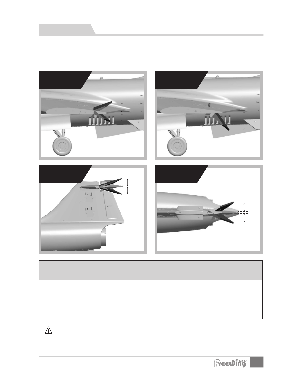
根据我们的测试经验,我们认为,按以下参数来设置副翼和升降舵的大、小舵,将有助于飞行。
在小舵角的情况下,飞机的可操控性能会好一些,适合初次飞行或者不太熟练的玩家飞行。而大舵角
的设置,可以提高动作灵敏度,使用经验丰富的玩家。您可以根据自身的情况,来选择其中一种舵量
进行飞行!
32
大 、 小 舵 参 数
中文版
副 翼
H1
H2
H1
襟 翼
H1
H2
H1
H2
方向舵
升降舵
Item N o.:FJ310
F-104S Starfighter
副 翼
升降舵 方向舵 襟 翼
小舵角
H1/H2 20mm/20mm
:80%舵量比率
H1/H2 35mm/35mm
:80%舵量比率
H1/H2 22mm/22mm
:75%舵量比率
H1 27mm
大舵角
H1/H2 25mm/25mm
舵量比率:100%
H1/H2 43mm/43mm
:100%舵量比率
H1/H2 27mm/27mm
:100%舵量比率
H1 41mm
飞行注意事项:打开襟翼飞行会有轻微低头,建议打开小舵角襟翼时设置6%的升舵配平,打开
大舵角襟翼时设置12%的升舵配平。
R
Page 34
Add.:
FeiYi Building,face to Labor Bureau, Fumin Middle Road, Dalang Town,
Dongguan City,Guangdong Province, China
HK Freewing Model International Limited
东莞 市飞翼 电子 科 技有 限公 司
香 港 飞 翼 模 型 国 际 有 限 公 司
地址: 广东省东莞市大朗镇富民中 路402-4 08号 飞 翼 楼 四 楼
Web: http://www.sz-freewing.com
Email:[email protected]
Tel: 86-769-82669669 Fax:86-769-82033233
Web: http://www.sz-freewing.com
Email:[email protected]
Tel: 86-769-82669669 Fax:86-769-82033233
Dongguan Freewing Electronic Technology Ltd
R
 Loading...