

Page 1
www. sz- fr eewing. com
EN 1~15
中
16~30
R
1/10 Scale Twin 80mm EDF JET
User Manual
Wingspan:1700mm(66.9")
Weight:4250g (w/o Battery)
Length:1551mm(61.1")
Page 2
1
A-10 Thunderbolt II
Item No .: FJ 311
Thank you for purchasing our Freewing 80mm EDF jet A-10 thunderbolt II. The original A-10
Thunderbolt II is a single-seat twin-engine attack plane, produced by Fairchild. It is now the only
continuous service jet in US Air Force to provide intensive support for the ground forces.
The Freewing 80mm EDF A-10 Thunderbolt II's length is 1551mm (61.1”), wingspan is 1700mm
(66.9”).The main wing and horizontal tail have a hollow frame design which reduces the weight
effectively, and significantly increases main wing’s strength. Three control boards are installed on the
fuselage and both main wings . The ribbon wire connection reduces wire installation time, and increases
connection reliability. The model uses screws for assembly so you can assemble/disassemble it quickly
for convenience when carrying or shipping.
The A-10 Thunderbolt II model plane comes in a stock grey color scheme with most of the
factory decals installed. In the package, we include three different sets of fuselage decals, please
refer to the decal instructions and choose which set you want to use.
The A-10 Thunderbolt II model plane utilizes the newest 9-blade dual 80mm EDF with a
3530-1900KV brushless out-runner motor and 100A ESC. In flight, each side's continuous current is
about 85A. The A-10 Thunderbolt II model plane uses 2 x 5000mAh lipo batteries,the flight time is about
3.5 ~ 4 minutes, the max flight speed is about 180KPH / 110MPH.
The A-10 Thunderbolt II has excellent flight characteristics in both high and low speed flight as well as
excellent short takeoff and landing capabilities. The new 70mm nose wheel and 85mm rear wheels
allow you to operate from all types of runways.
Enjoy your new The A-10 Thunderbolt II !
Index
Introduction
Basic product information
Package list
PNP Assembly Instructions
Steel wire use instruction...................
Fuselage
Assembly
Horizontal stabilizer / Vertical stabilizer Assembly....
Engine compartment Assembly
Main wing Assembly
Missile Installation...
Scale accessories Installation
Pushrod instructions
1
2
2
3
3
3
4
4
5
6
6
Control board connection diagram..........
Battery size......
Center of gravity.......
Control direction test.......
Dual Rates and Pref
light Cautions....
Accessories Description
Servo Introduction...........
Parameter of motor.......
Motor and 90mm EDF power system instruction Installation.........
Pushrod Installation
Nose landing gear installation
Main landing gear installation
7
8
8
9
10
11
11
12
13
14
15
1. This is not a toy! Operators should have some basic experience. Beginners should operate only under the guidance
of a professional instructor.
2. Before beginning assembly, please read through the instructions and carefully follow them throughout the build.
3. Freewing and it's vendors will not be held responsible for any losses due to improper assembly and operation.
4. Model airplane operators must be at least 14 years of age.
5. This airplane is made of EPO foam material, covered with surface spray paint. Don't use chemicals to clean as it may
cause damage.
6. You should avoid flying in areas such as public places, areas with high voltage power lines, nearby highways, airports
or in other areas where laws and regulations clearly prohibit flight.
7. Do not fly in bad weather conditions, including thunderstorms, snow, etc...
8. Lipo batteries should be properly stored in a fire proof container and be kept at a minimum of 2M distance away from
flammable or explosive materials.
9. Damaged or scrap batteries must be properly discharged before disposal or recycling to avoid spontaneous combustion
and fire.
10. At the Flying Field, properly dispose of any waste you have created, don't leave or burn your waste.. Ensure that
your throttle is in the low position and that your radio is turned on before connecting the Lipo battery.
11. Do not attempt to catch this model while in flight. Wait until it comes to a complete stop before handling the airplane.
Page 3
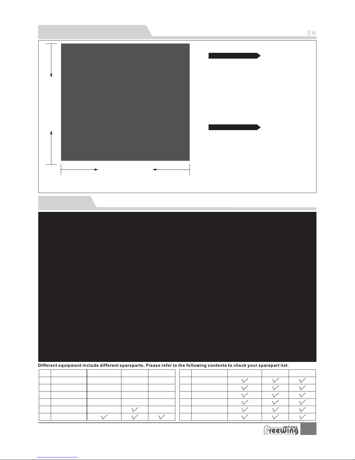
Package list
2
Basic product information
1700mm( 66.9")
1551mm( 61.1")
Material: EPO
Aileron: Yes
Flap: Yes
Elevator: Yes
Rudder: Yes
Landing gear: Retract landing gear
Landing gear doors: electric nose gear doors
Scale LED lights
Scale Pilot figure
2
Wing loading: 124g/dm
Motor: 3530-1900KV
brushless outrunner motor
Ducted fan: 80mm 9-blade fan
ESC: 100A brushless UBEC 8A(2pcs)
Servo: 17g Digital MG servo (9pcs)
30g Digital MG servo (2pcs)
9g Digital MG servo (1pcs)
Weig ht: 4 250 g(w ith out battery)
Thrust: 6600kg
Standard version
Other features
A-10 Thunderbolt II
Item No .: FJ 311
1
2
3
4
5
6
PNP
ARF Pl us
Airf rame
PNP
ARF Pl us
Airf rame
7
8
9
10
11
12
No. Name
No.
Fuse lage
Main w ing
Hori zonta l tail
Verti cal tai l
Carb on tube
Engine compartment
Pre -inst alled a ll
ele ctron ic part s
Pre -inst alled a ll
ele ctron ic part s
Pre -inst alled a ll
ele ctron ic part s
Pre -inst alled a ll
ele ctron ic part s
Pre -inst alled a ll
ele ctron ic part s
Pre -inst alled
ser vo
Pre -inst alled
ser vo
Pre -inst alled
ser vo
Pre -inst alled
ser vo
No el ectro nic
equ ipmen t
No el ectro nic
equ ipmen t
No el ectro nic
equ ipmen t
No el ectro nic
equ ipmen t
No el ectro nic
equ ipmen t
Link age Set
Scale ac ce ss or ie s
Stab ilize r wing
Manual & D ec al s
Glue & Non-slip mat
Screws
Name
Note:
The parameters stated here are derived from test results using our
accessories.
If you use other accessories, the test results will differ. We
cannot provide
technical support if you have a problem when using other accessories.
Page 4
3
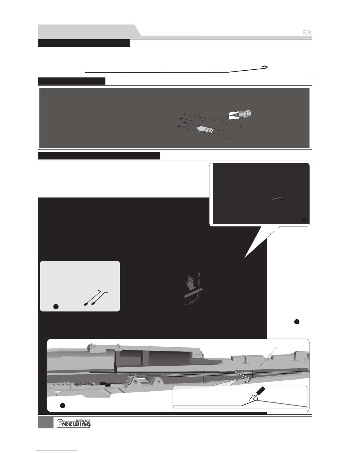
PNP Assembly instructions
Use glue to assemble the front/rear fuselage.
AB-
Carb on tu be (Ø6x20 0m mm m)
Carbon square tube (8. 5x 8. 5x 80 0m m)
A
B
Step
4
Step
3
Batter y compartment
Elevator/rudder servo cable
Tra cti on st eel w ire
Step
1
A
B
C
D
As shown in the photo:
1.Attach the vertical stabilizer to the horizontal stabilizer and use the
2 screws to attach the left/right vertical stabilizer.。
2.When installing the vertical stabilizer, pull the rudder servo cable wires
through the inside trough。
3.Use the metal wire to pull the elevator/rudder servo cable wires through
4.
to the battery compartment.
Attach the horizontal stabilizer to the
rear of the fuselage and use the 4
screws to secure it.
A- Screws (PA3x8 4pcs)
B- Vertical tail
C- Horizontal tail
D- Servos wire
E- Screw s (PA3x8 4pcs)
E
Step
2
Steel wire use instructions
Our tests show that excessively long servo extension lines increase the rise of poor connections that can lead to servo
brown outs or failure, causing accidents during flight. Instead, this kit contains a steel wire that can be used to pull the
main wing/elevator and rudder servo wires through the airplane to the battery compartment, eliminating the need for
extension wires.
Fuselage Installation
A-10 Thunderbolt II
Item No .: FJ 311
Horizontal stabilizer / Vertical stabilizer assembly
Page 5
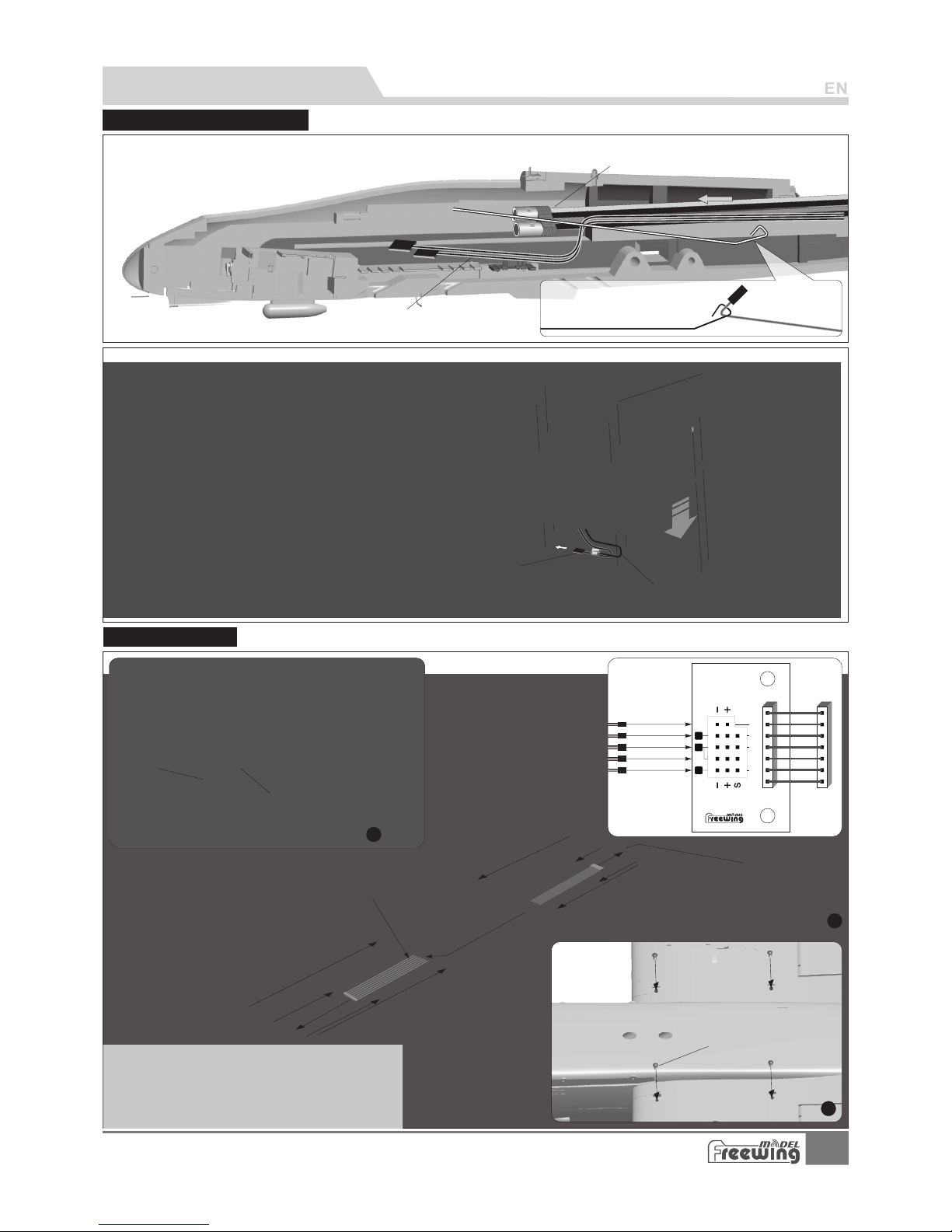
Engine compartment assembly
Step
2
4
EC5
1.Use the metal wire to pull the ESC cable and throttle cable to the battery compartment.
2.Assemble the engine compartment to the rear of fuselage.
3.Use 6 screws to secure it。
Screw ( 6pcs )PA3x 12
Step
1
A I L
FLAP
GEAR
LIGHT
1
6
5
Air leron
Fla p(Two)
Lan ding ge ar
Win g tip lig hts
Fla p(One )
Mai
n w
ing trough p or t
Carbon tube A
(Ø12 x570m m)
Carbon tube B
(Ø8x65 0mm)
Step
3
Ribbon wire
Control board
1.Insert the carbon tubes
A and B into the fuselage.
2.Insert the connection cable to the control board,
then install the left and right main wings to the
fuselage.
3.Use 4 screws to secure the main wing.
Screw
(PWM 4x8 4pc s)
Throttle wire
Batter y compartment
Steel wire
ESC/Battery wire
Back of fuselage
ESC/Battery wire
Throttle wire
PNP Assembly instructions
Mainwing assembly
A-10 Thunderbolt II
Item No .: FJ 311
Page 6
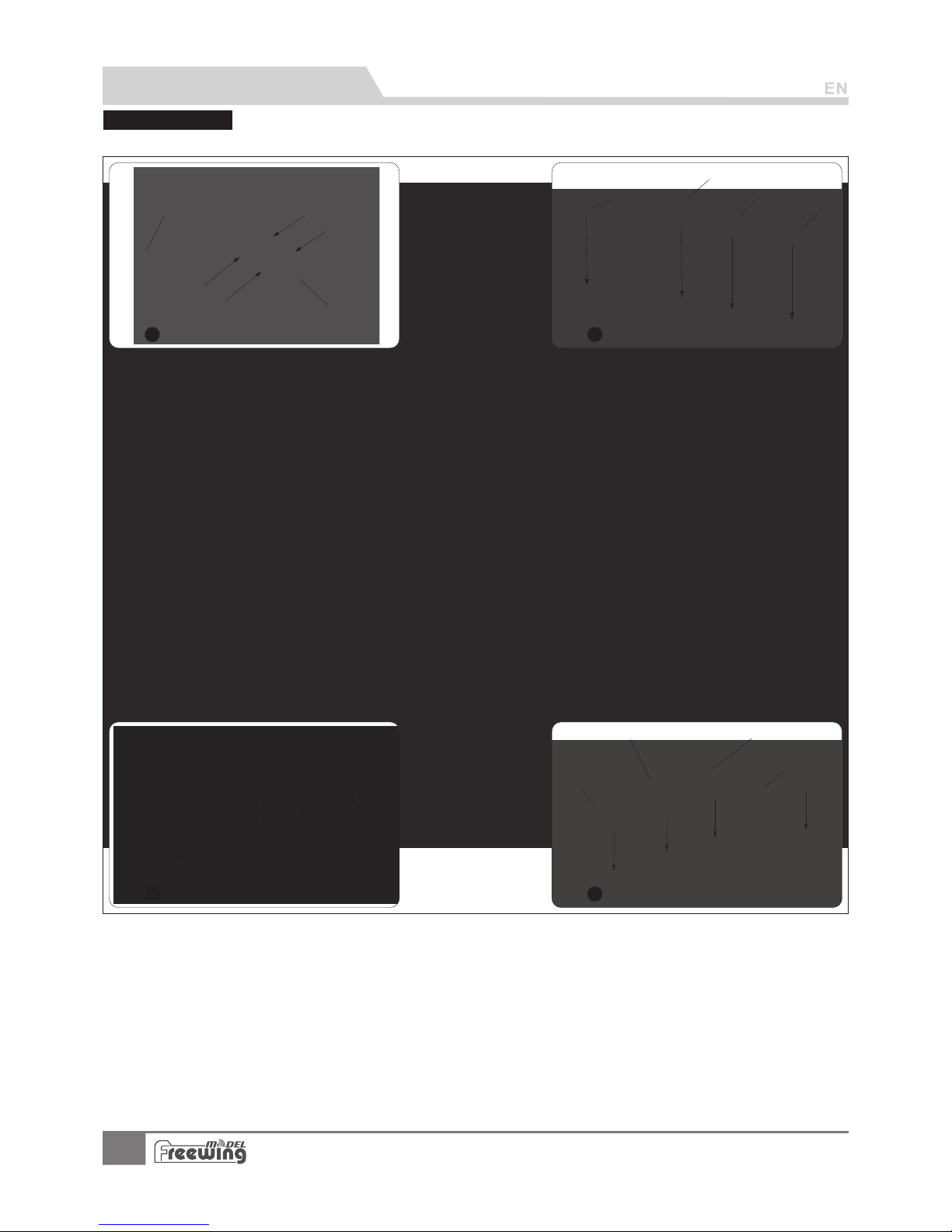
Missile Installation
Step
1
Step
2
Step
3
Step
4
AIM- 9 pylon s
AIM- 9 Missi le s
AGM- 65 Miss il es
Mk-84
Mk-84
AGM- 65 Miss il es
LAU- 131
AN/A LQ-13 1
Follow the pictures below to install the weapons
PNP Assembly instructions
5
A-10 Thunderbolt II
Item No .: FJ 311
pylo ns 1
pylo ns 2
pylo ns 3
pylo ns 4
Page 7
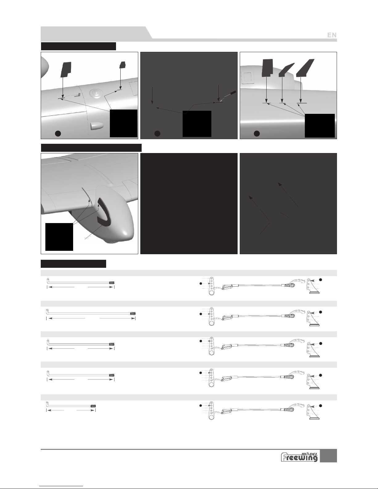
Step
1
Step
2
Step
3
Screw
(PM3 x6 1p cs)
Radar
Screws
(PA3x 8 2pcs)
Wing fence
34mm
63m m
(2- 1/2")
2
3
1
4
5
1
2
3
48m m
(1- 7/8")
2
1
4
5
3
1
2
3
76m m
(3" )
63m m
(2- 1/2")
2
1
4
5
3
1
2
3
63m m
(2- 1/2")
PNP Assembly instructions
Antennalnstallation
Pushrod instructio ns
Flap pushrod size(Outside) Flap pushrod mounting hole(Outside)
Flap pushrod size(Inside) Flap pushrod mounting hole(Inside)
Aile ron pus hr od size
Aile ron pus hr od moun ting ho le
Rudd er p ush ro d size
2
3
1
4
5
1
2
3
Rudd er p ush ro d mount ing hol e
Elev ator pu sh rod siz e
Elev ator pu sh rod mou nting h ol e
Pus hrod di amete r Ø1. 5 mm
Pus hrod di amete r Ø1. 5m m
Pus hrod di amete r Ø1. 5 mm
Pus hrod di amete r Ø1. 5 mm
Pus hrod di amete r Ø1. 5m m
2
3
1
4
5
1
2
3
Radar and Wing Fence Installation
6
A-10 Thunderbolt II
Item No .: FJ 311
Stabilizer wing
Page 8
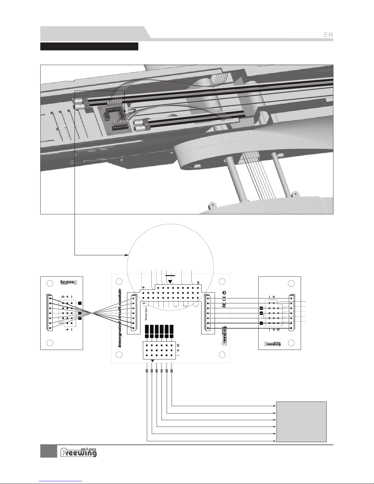
PNP Assembly instructions
Ser vo lnpu t
Rec eiver
A-10 Thu nde rbolt I I
6
5
4
3
1
2
E L E
T HR
RU D
GEAR
Nose Steering
GEARDOOR
Landing lights
FLAP
GEAR
RUD
E LE
A I L
T HR
1
6
5
A I L
FLAP
GEAR
LIGHT
Main wi ng c on tr ol b oa rd (R ig ht)
Main wing control board(Left )
1
6
5
A I L
FLAP
GEAR
LIGHT
Landing lights
Landing gear door
Landing gear
Nose steering
Rudder
Throttle
Elevator
EC5
A-10 Thunderbolt II uses ribbon wires for convenience. Please refer to the following photo for connecting the electronic
equipment.
Control board con nec tio n dia gra m
Airleron
Flap(Two)
Landi ng g ea r
Win g ti p li gh ts
Flap(One)
Strobe light
Connect the aileron channel to the receiver
Connect the elevator channel to the receiver
Connect the throttle channel to the receiver
Connect the rudder channel to the receiver
Connect the landing gear channel to the receiver
Connect the flap channel to the receiver
RECEIVER
7
A-10 Thunderbolt II
Item No .: FJ 311
Page 9
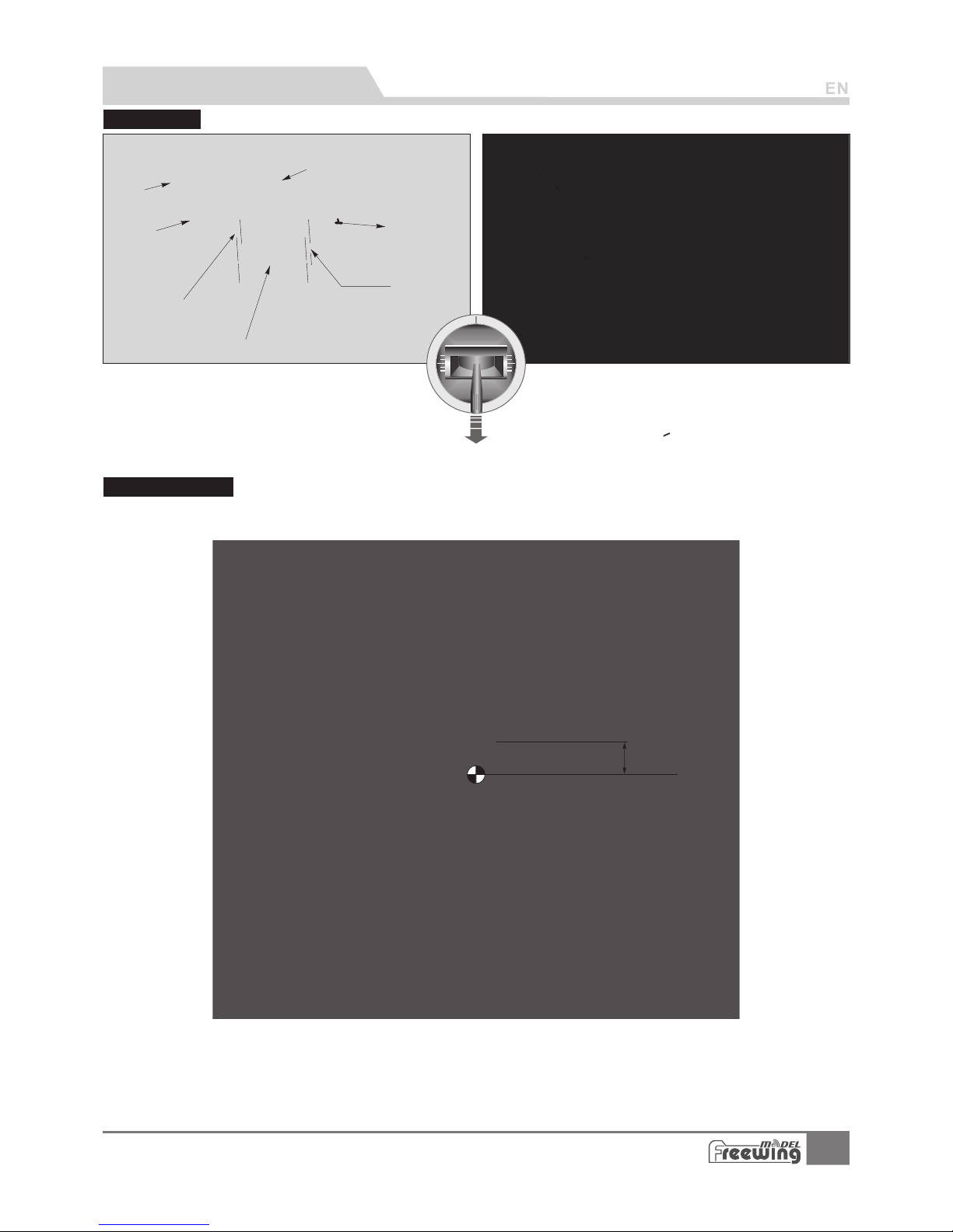
Battery size
Before connect the battery and receiver, turn on
your transmitter, select the desired model channel
and make sure the throttle stick is in the lowest
position. We recommend assigning a switch as a kill
switch.
Battery compartment size:
L
=360 W=90 H=90(mm)
BatteryA
Battery B
Velcro A
Velcro B
Battery tr ay
Screws
(PA3x 8 8pcs)
P
ull t h
e sti cker ba ck
and o pen the c ockpi t.
Battery in st al l on t he f ro nt o f
fusela ge , an d us e ma gi c ta pe t o fi x.
Canopy/battery hatch door
78mm
(3-1/16")
PNP Assembly instructions
We recommend the following battery capacity and
discharge rate:
6S 22.2V 4000mAh ~ 6S 22.2V 5200mAh (2pcs)
Discharge rate of C>30C
Center of gravity
8
A-10 Thunderbolt II
Item No .: FJ 311
Place the first battery into the
forward position and secure it
with the velcro strap.
The Center of Gravity is directly related to the flight
characteristics the airplane will demonstrate on it's first flight. As
a starting point, we recommend using 78 mm. Achieve this CG
by moving the batteries. If, for some reason moving the batteries
does not allow you to reach the proper CG, another suitable
material such as sticky backed weight can be utilized.
As you become more accustomed to the airplane, you can adjust
the CG to meet you're individual taste.
Page 10
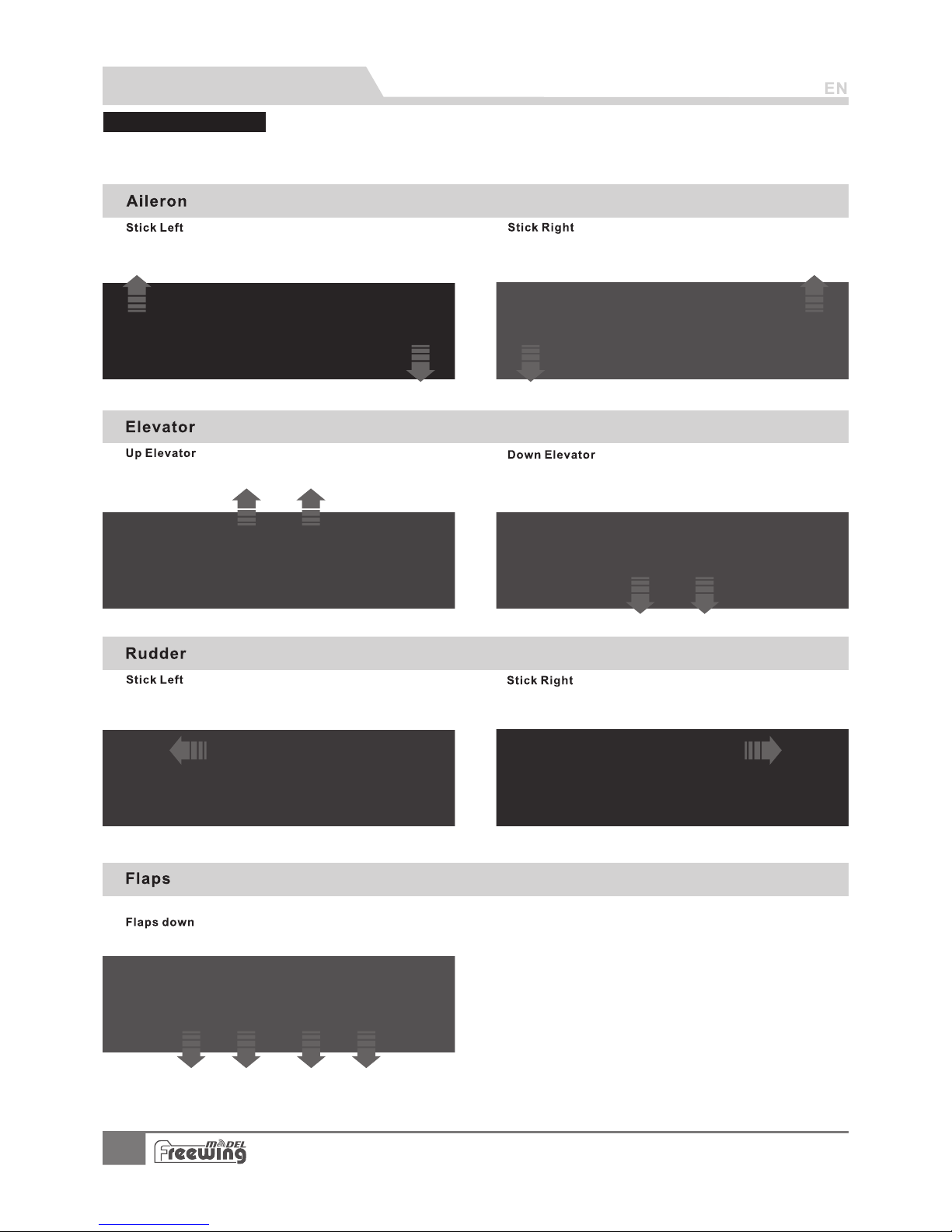
Control direction te st
PNP Assembly instructions
9
A-10 Thunderbolt II
Item No .: FJ 311
After the airplane is assembled, but before the first flight, ensure that your control
surface directions are correct. Turn on the transmitter and set the throttle in it's the
lowest position, then test the control surfaces individually to ensure correct
movement.
Page 11
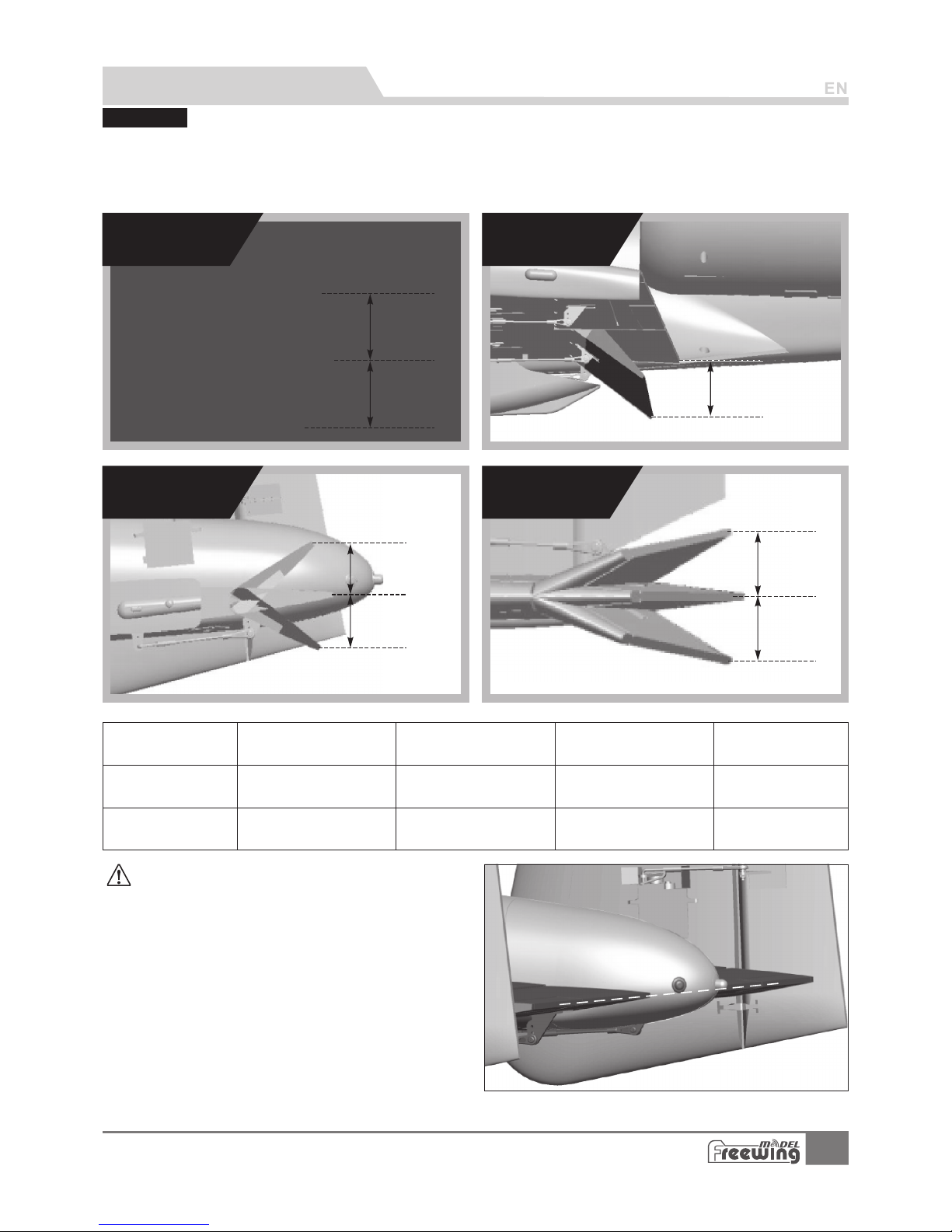
From our flight test results, we recommend the following parameters for aileron/elevator rates. In
low rates, the airplane will be more stable. In high rates, it will be more sensitive. We advise using the
recommended high rates in your first flight, then trying the recommended low rates.
Afterwards can may want to adjust the rates to suit your individual taste.
Low Rate
High Rate
Aileron
H1/H 2 30mm/ 30 mm
D/R Ra te: 70%
H1/H 2 40mm/ 40 mm
D/R Ra te: 100 %
H1/H 2 30mm/ 30 mm
D/R Ra te: 85%
H1/H 2 34mm/ 34 mm
D/R Ra te: 100 %
H1/H 2 20mm/ 20 mm
D/R Ra te: 85%
H1/H 2 26mm/ 26 mm
D/R Ra te: 100 %
H1 32m m
H1 50m m
H1
H2
H1
H1
H2
H1
H2
PNP Assembly instructions
Aileron
Flaps
Elevator Rudder
Elevator Rudder
Flaps
Dual rate s
Preflight precautions:
10
1.Correct elevator center position
After assembly, adjust the elevator to
center its position, please refer to the photo.
After adjusting, the surface should look as if it has a little up
elevator.
Flap-elevator mix parameter
When deploying the flaps, the jet will tend to fly tail heavy. In
order to correct this, we recommend a 'Flap/Elevator' mix
within your radio. In this case, when you deploy the flaps, the
airplane will maintain level flight.
Setting range is as following:
Deploy flaps to 50mm, pre-set the elevator 3mm down.
Deploy flaps to 32mm, pre-set elevator 2mm down. Fine tune
these settings according to your individual taste.
A-10 Thunderbolt II
Item No.:FJ311
Page 12
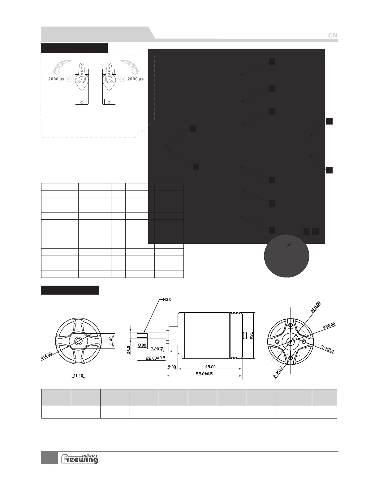
Servo Introduction
Lan ding ge ar door
No.
Pos./R ev.
Cable le ng th
1
2
3
4
5
6
7
8
9
10
11
12
Positi ve
Positi ve
Positi ve
Positi ve
Positi ve
Positi ve
Positi ve
Positi ve
Positi ve
Revers e
Positi ve
Positi ve
600m m
600m m
600m m
600m m
120m m
120m m
360m m
360m m
950m m
950m m
1200 mm
1200 mm
Model
1
2
3
5
7
4
6
8
9
10
Unit: (mm)
3530 -1 90 0K V
11 12
O/R BL 35 30
Item N o.
Use mo tor
moto r(KV) Thrust (k g)
Curr ent(A )
Use voltage
(V)
Use ES C
(A)
EDF Weight
(g)
Max po we r
(W)
Efficiency
(g/w)
1900
22.2 (6 S)
3300 90 100 278 2000 1.65
Accessories Description
If you choose not to use the factory servo, please refer to the
following list to ensure the selected servo is the correct size.
Positi on
Ailero n(L)
Ailero n(R)
Flap(L )
Flap(R )
Flap(L )
Flap(R )
Elevator (L )
Elevator (R )
Rudder(L )
Rudder(R )
Nos e gear
ste ering s ervo
Motor Parameters
11
A-10 Thunderbolt II
Item No .: FJ 311
MO035303
E723 10
17g Digi ta l MG
9g Digital M G
30g Digi ta l MG
30g Digi ta l MG
17g Digi ta l MG
17g Digi ta l MG
17g Digi ta l MG
17g Digi ta l MG
17g Digi ta l MG
17g Digi ta l MG
17g Digi ta l MG
17g Digi ta l MG
A servo or reversed servo is defined as follows:
When the servo input signal changes from
1000ųs to 2000ųs, if the servo arm rotates
clockwise, it's a positive servo. If it rotates
counter clockwise, it's a reversed servo.
Page 13
Motor installation
A
B
C
D
E
F
G
H
I
J
A
B
C
D
E
F
G
H
I
J
ABCDE-
ESC fixed mount
ESC
ESC fixed part
Screw (PA3x8 4p cs)
Power system fixed mount
F GHI J -
80mm EDF power system
Screws (PWA3x8 4pcs)
Plastic cover
Engine compartment cover
Screws (PA3x8 4pcs)
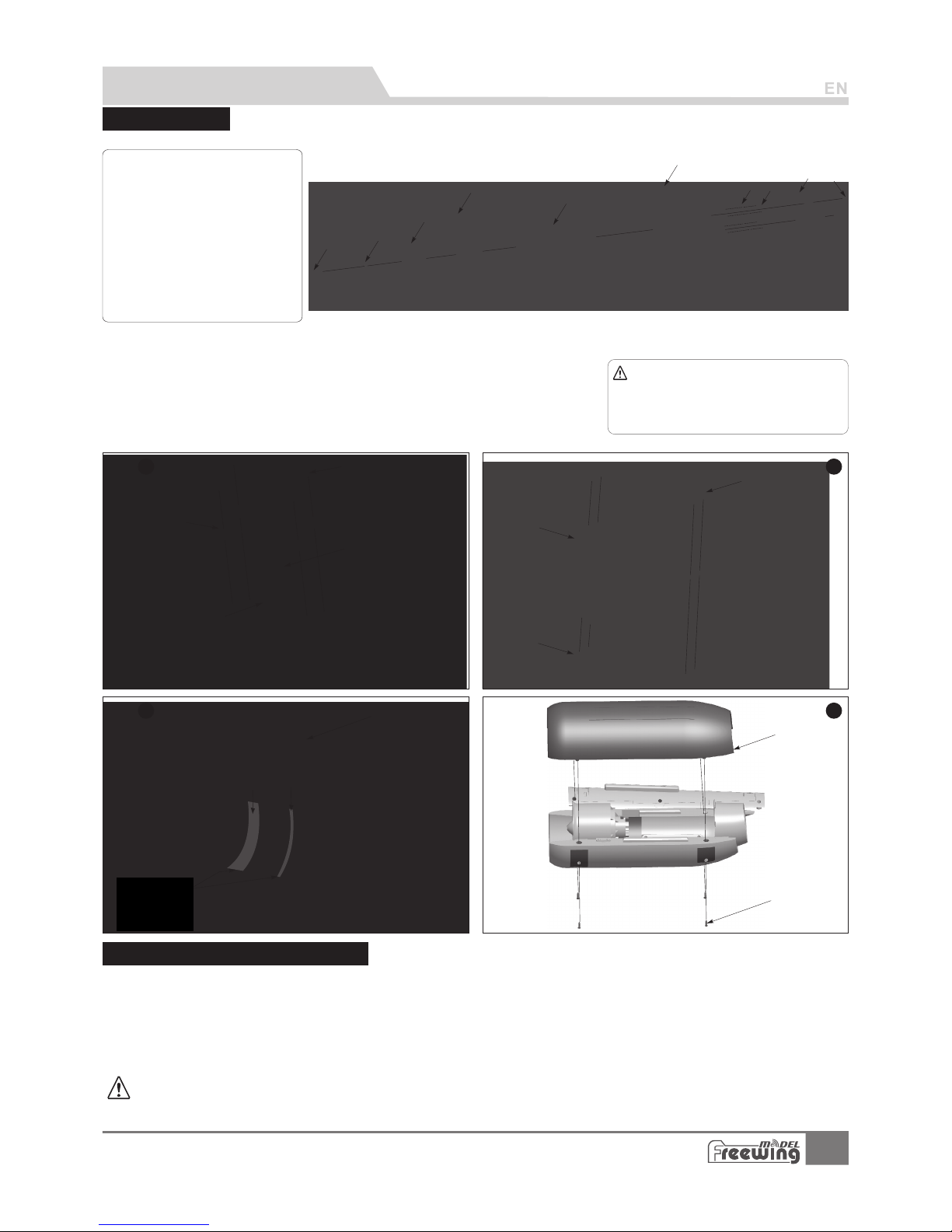
Accessories Description
Refer to the following diagram to install the ESC and power system:
Note: When ESC and battery connected, do
not touch them by hand to avoid accidental
injury. When testing an EDF, use a proper test
stand. Don't touch the EDF wihile testing
Step
2
Step
3
Step
4
Step
1
Standard version
A B CDE -
F GHI J -
Scre w
Moto r spi nner
Cup he ad sc rews (M 3x 7 4p cs )
Was her
80mm d uct ed fan fr ame
for ou tru nner mo tor
3530 -19 00KV mo tor
80mm 9 -bl ade duc ted f an
Spin ner
Was her
Cup he ad sc rews (M 3x 12 1 pc s)
1. We have optional power systems available for the A-10.You may want to use one of these, just follow the above
steps, the dimensions are suitable for all Freewing 90mm EDF power system and 130A ESC.
2. ESC cable specification:
The cable length for motor output port: 100mm
The cable length for power port: 200mm
3. Note:An alternate brand of power system and ESC might not fit in this engine compartment, check the
dimensions before purchasing.
90mm EDF power system instruction
12
A-10 Thunderbolt II
Item No .: FJ 311
Page 14
Aileron and Flap pushrod Installation
ABC-
Servo
Elevator pushrod
Elevator horn
A
B
C
ABCD-
Servo
Main wing pushrod
Aileron horn
Main wing servo trough
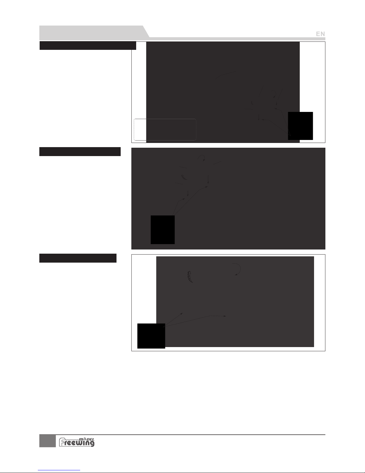
Accessories Description
Elevator pushrod Installation
Rudder pushrod Installation
1.Use a servo tester or a
transmitter to center the servo.
2.Use glue to install the servo and
aileron horn to the main wing.
3.Feed the servo cable through
the trough, when completed for
all the servos, apply the decal
over the trough.
4.
5.
Insert one end of the pushrod into
the servo arm and adjust its
length. And secure the clevis to
the aileron horn.
Repeat the above four steps to
install the other clevis' for the flap,
then repeat the procedure for the
other aileron and flap servo.
1.Use a servo tester or a transmitter
to center the servo.
2.Use glue to install the servo and
elevator horn on the elevator.
3.Feed the servo cable through the
trough, when completed for all the
servos, apply the decal over the
trough.
4.Insert one end of the pushrod into
the servo arm and adjust its
length. Secure the clevis to the
elevator horn.
5.Repeat the above four steps for
the other side of the elevator.
1.Use servo tester or a transmitter
to center the servo.
2.Use glue to install the servo and
rudder horn on the rudder.
3.Feed the servo cable through the
trough, when completed, apply
the decal over the trough.
4.Insert one end of the pushrod into
the servo arm and adjust its
length. Secure the clevis to the
rudder horn.
5.Repeat the above four steps for
the other rudder.
ABC-
Servo
Rudder pushrod
Rudder horn
Note:
: T he re i s a EPO glu e on
packa ge , Ple as e use it to glu e.
Glue sh ou ld be sp re ad ev en ly
and wai t fo r 90 seco nd s. Th en
insta ll o n, i ts b es t gl ue c on di ti on.
A
B
C
D
13
A-10 Thunderbolt II
Item No .: FJ 311
Page 15
Nose landing gear assembly
Pus hrod di amete r Ø1.5m m
( 2-7 /8")
68m m
Step
1
Step
2
Step
3
Step
4
Step
5
Step
6
Step
7
Step
8
Step
9
A
B
C
D
F
E
G
H
I
J
K
L
M
M1
N
O
P
Q
S
T
U
V
W
X
Y
Z
Z1
Step
12
Step
11
Step
10
AB
AC
AD
AE
AF
AG
AH
AI
AJ
AK
AM
AN
AO
AP
AQ
AR
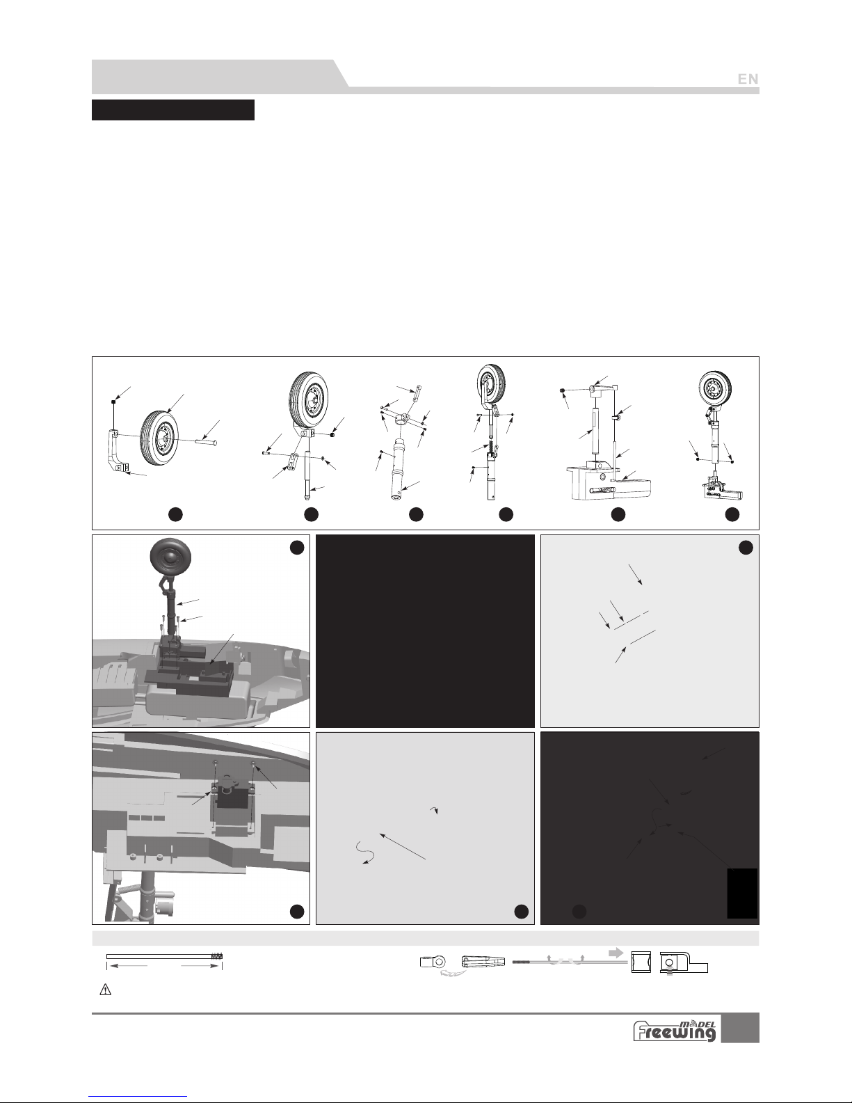
Please assemble、disassemble the rear land ing g ear a cco rdi ng to t he fo llo win g photo.
R
A B C D E F GH I J K L MN O-
Nose gear axle
Nose wheel ( Ø mm)70x2 0
Grub Screw (M4x3)
Nose gear slant strut
GrubScrew (M4x3)
Pin (Ø 3.5 X9 .2mm)
H-Strut
C-Clip (Ø1.5mm)
Nose gear shock absorber active rod
8-shape connecting arm
Pin (Ø3.5X9.2mm)
C-Clip (Ø1.5mm)
Screw (PM 2x3 2 pc s)
Screw (PM 2x4 1 pc s)
Nose gear strut
P-
Q-
RS-
T-
U-
V-
W-
X-
YZ-
ABACAD-
Pin (Ø 3.5 X9 .2mm)
(Ø1. 5mm)C-Buckle
Spring
Screw (
PM2x4 1pcs)
GrubScrew (M3x3)
L-shape rotating arm Oshape ring
Pushrod
Nose metal wire Retract
controller
Grub Screw (M4x4)
Nose landing gear Screw
(PWA3x12 4pcs) Nose
landing gear mount
A E A F AGAH A I A J A K A L AMAN AOA P AQAR -
Screw (PA2 x8 1 pcs)
LED lights
LED light fixed arm
Screw (PM 2x3 1 pc s)
Nose landing gear door type
Spring
Screw (PWA3 x8 1 pcs)
Screw (PWA2 .3 x6 1pcs )
Servo
Screw (PWA2 x8 1 pcs)
Nose steering pushrod
Gear door servo
Gear door pushrod
Nose cabin door
AL
Nose s teeri ng p ush ro d size
Serv o pushr od i nst al ling ho le
Note:When installing, please check the position of the flat spot on the spare part. When
setting the grub screw,the flat position must face
towards the screw hole, so that the grub screw anchors the part into place.
Accessories Description
14
A-10 Thunderbolt II
Item No .: FJ 311
Page 16
Main landing gear
Assembly
Step
1
Step
2
Step
3
A
C
B
D
E
E1
F
G
G1
H
I
I1
J
K
K1
L
M
N
O
Step
4
Step
5
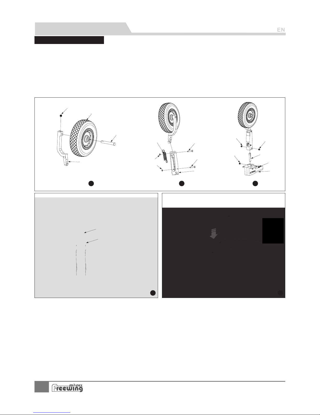
AB CDE F GH-
Main gear axle
Main wheel (Ø85x26mm)
Grub Screw (M4x3)
L-Sl ant str ut
Pin (Ø 3.5 X9 .2mm)
Spring
C-Clip (Ø1.5mm) Main
Gear strut
I J K L -
M-
N O-
Accessories Description
15
A-10 Thunderbolt II
Item No .: FJ 311
When assembling or disassembling the main landing gear, refer to the following diagram
Grub Screw (M4x3)
Main gear main rod
Grub Screw (M4x3)
Electronic retract
Main landing gear
Screw (PWA3x12 4pcs)
Main gear plastic cover
Page 17
Add.:FeiYi Building,face to Labor Bureau, Fumin Middle Road, Dalang Town,
Dongguan City,Guangdong Province, China
HK Freewing Model International Limited
东莞市飞 翼 电 子科技有限 公 司
香 港 飞 翼 模 型 国 际 有 限 公 司
地址: 广 东 省东 莞市大 朗镇 富 民中 路4 0 2-40 8号 飞翼 楼 四楼
Web: http://www.sz-freewing.com
Email:[email protected]
Tel: 86-769-82669669 Fax:86-769-82033233
Web: http://www.sz-freewing.com
Email:[email protected]
Tel: 86-769-82669669 Fax:86-769-82033233
Dongguan Freewing Electronic Technology Ltd
R
 Loading...