

© Prism Medical UK 2014
E Series User Manual Rev 03—Feb 2015 page
User Manual
Use and Care ● Fault Finding ● Warranty Information
E-Series Mobile Hoists
Unit 1, Tir Llwyd Industrial Estate, St Asaph Avenue, Kinmel Bay, Nr Rhyl, Conwy, LL18 5JA
info@prismmedical.co.uk Tel +44 (0)844 980 2296 www.prismmedical.co.uk

© Prism Medical UK 2014
E Series User Manual Rev 03—Feb 2015 page 2
Table of Contents
E-Series Mobile Hoist Range
1.0 Assembly instructions
1.1 Initial Assembly 3
2.0 Hoist Features
2.1 Emergency Stop Button 5
2.2 Emergency Lowering / Raising 6
2.3 Foot bar / Tip Bar 7
3.0 Operating instructions
3.1 To Alter the Leg Width 8
3.2 Positioning 8
3.3 Raising & Lowering 9
3.4 Battery Charging 9
3.5 Handset 10
3.6 Sling guide 10
3.7 Sling Types 11
4.0 Safety precautions 12
5.0 Safety Checks
5.1 Daily Check List 14
5.2 Warning Notes 14
6.0 Technical Specification
6.1 Dimensions & Weights 15
6.2 Sound Levels 15
6.2 Maximum lifting Height & leg width 16
6.3 Electrical detail 16
7.0 Fault Finding / Maintenance
7.1 Fault Finding 17
7.2 Service / Maintenance 17
7.3 Cleaning & Sterilisation 17
Declaration of Conformity 18
8.0 Test certificate & Guarantee 19
9.0 Testing and service record
10.1 Initial Information 20
10.2 Service record History 21
© Prism Medical UK 2014
E Series User Manual Rev 03—Feb 2015 page 3
1.0 ASSEMBLY INSTRUCTIONS
Freeway E Series Mobile Hoist
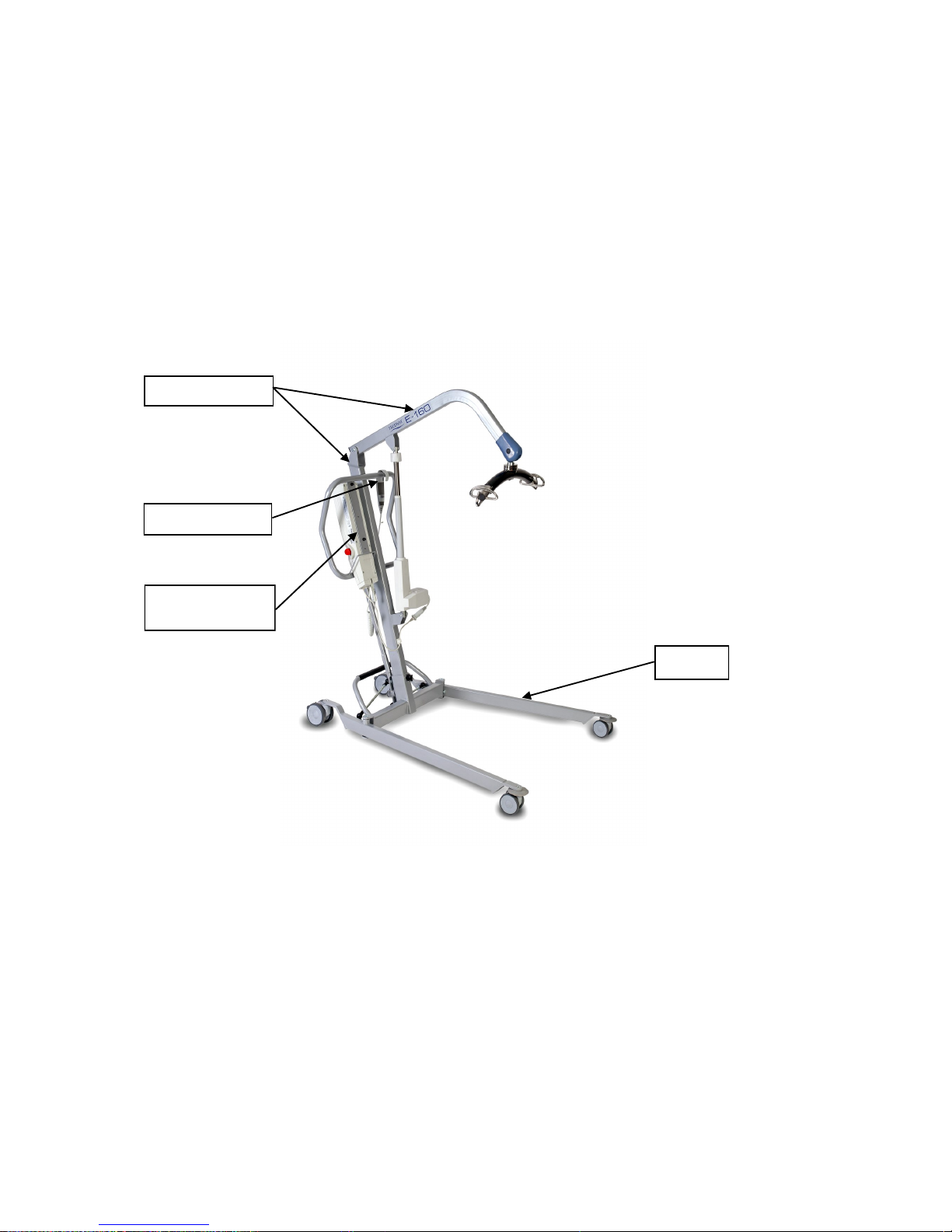
1. Remove carefully from the box:
Boom / Mast assembly
Base unit with legs attached (Base Unit)
Charging lead
Hand set control
Leg adjusting lever
Base Unit
Boom / Mast assembly
Control box / Battery
pack
Handset Control
SAFETY NOTE: Some of the parts are heavy and will need to be lifted with
care. Heavier items may need two people to lift. ( please refer to technical
details on page 15 )
2. Place base unit on level floor surface and lock rear castors.
3. Remove boom/mast assembly from packaging
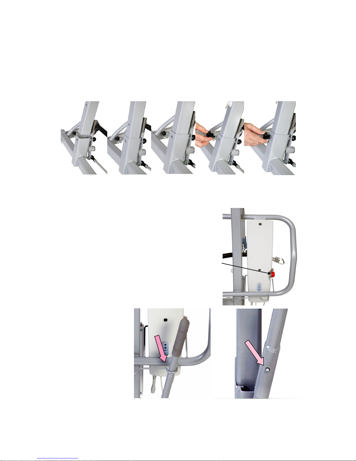
4. Carefully take boom/mast assembly and slide bottom of mast into base socket,
as shown in photo’s on page 4. When the mast is fully engaged into the base
socket locate the mast locking knob and tighten firmly by hand.
Continued….
© Prism Medical UK 2014
E Series User Manual Rev 03—Feb 2015 page 4
1.0 ASSEMBLY INSTRUCTIONS
Freeway E-Series Mobile Hoist
4 - cont.
Ensure that the mast is fully down before fitting the mast
securing knob
SAFETY NOTE: Possible finger trap. Keep fingers away from
end of mast when fitting to base unit.
SAFTEY NOTE: Possible finger trap. Keep fingers away from
end of leg lever adjuster when fitting to retaining bar.
5 The control unit is already fitted to the mast,
so assembly is not required.
Check the emergency stop button (red button)
located on the control box is in the out position
(i.e. out)
6 To fit the adjustable
leg lever, insert through
top location bar and onto
retaining bar on base
assembly. Align hole in
leg lever with retaining
pin and clip into position.
Emergency stop button
© Prism Medical UK 2014
E Series User Manual Rev 03—Feb 2015 page 5
Emergency Stop Button
Your HOIST IS NOW READY FOR USE
***PLEASE READ THE OPERATING INSTRUCTIONS
CAREFULLY—see page 8 ***
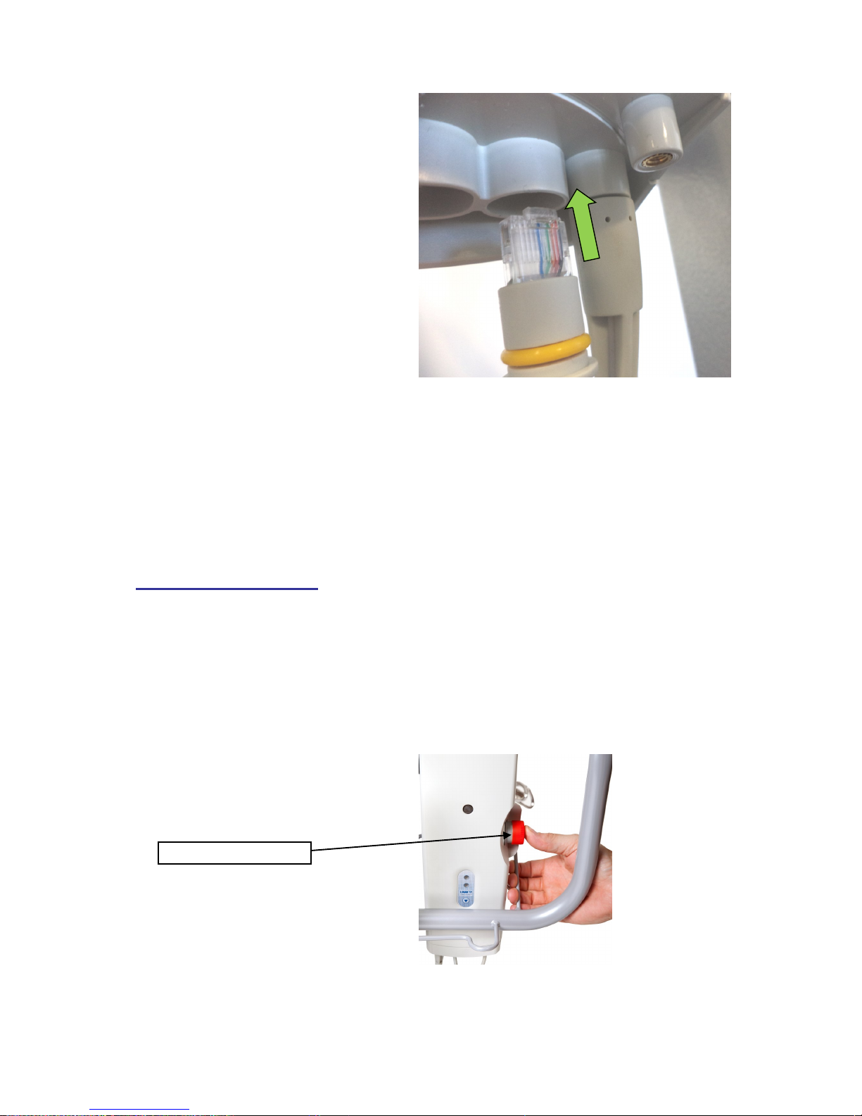
7 Fit the hand control unit to the
hand control socket located on the
base of the control unit.
NOTE: The hand control lead can
only be fitted in one orientation
into its socket. Do not use force
to insert the hand control plug
into its socket. The plug when
correctly inserted should be
pushed firmly home.
2.0 Hoist Features
2.1 Emergency Stop Button
During all operations and at all times, the stop button should be in the out position.
In the unlikely event of a failure of the handset control, it is possible that the electric
ram either continues to lift or continues to lower. This may be overridden by
pressing the Emergency stop button to stop the ram. To re-set the button after it
has been pressed, simply twist it slightly clockwise and the button will spring
outwards.
© Prism Medical UK 2014
E Series User Manual Rev 03—Feb 2015 page 6
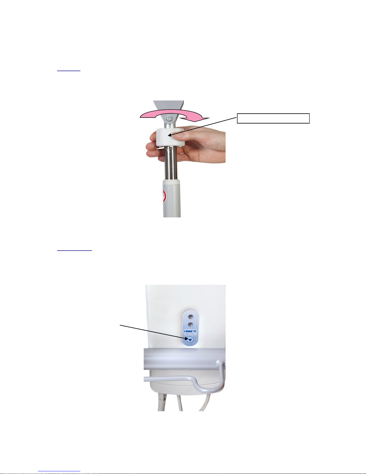
2.2 Emergency Lowering / raising
Manual emergency lowering is facilitated by turning the emergency lowering ring
clockwise. The ring is situated at the top of the actuator where the actuator connects
to the mast.
Electrical emergency lowering is facilitated by pressing the emergency lowering
button on the front of the control box unit. Battery MUST be charged, in order to
operate via this button.
Twist Clockwise to Lower
Emergency Lowering
Button
© Prism Medical UK 2014
E Series User Manual Rev 03—Feb 2015 page 7
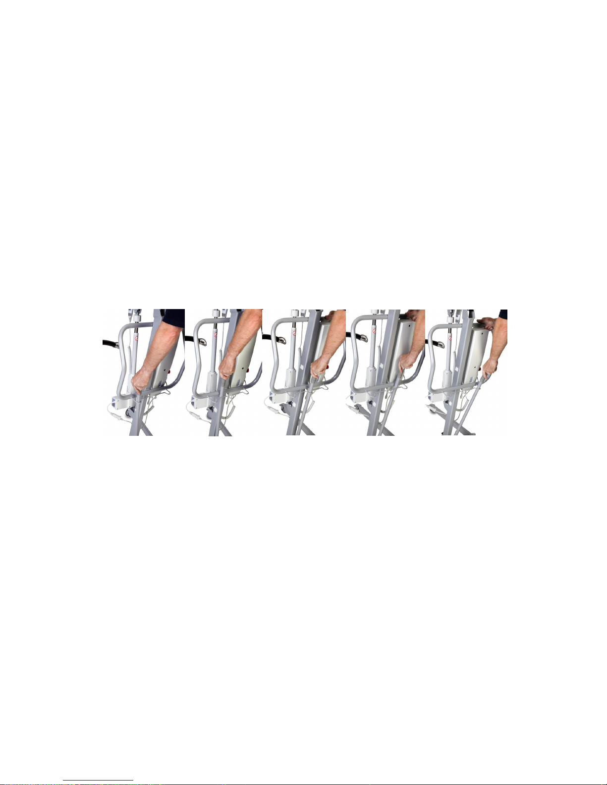
2.3 Foot Bar
The E-Series mobile hoist range has a foot bar situated at the rear of the base unit
to help facilitate the clearing of door thresholds and to help raise the front end when
loading the hoist into a vehicle for transport.
The bar has a non slip surface to maintain grip whilst being used.
The bar can also be used to aid the movement of the hoist on difficult surfaces
where the hoist doesn't move freely.
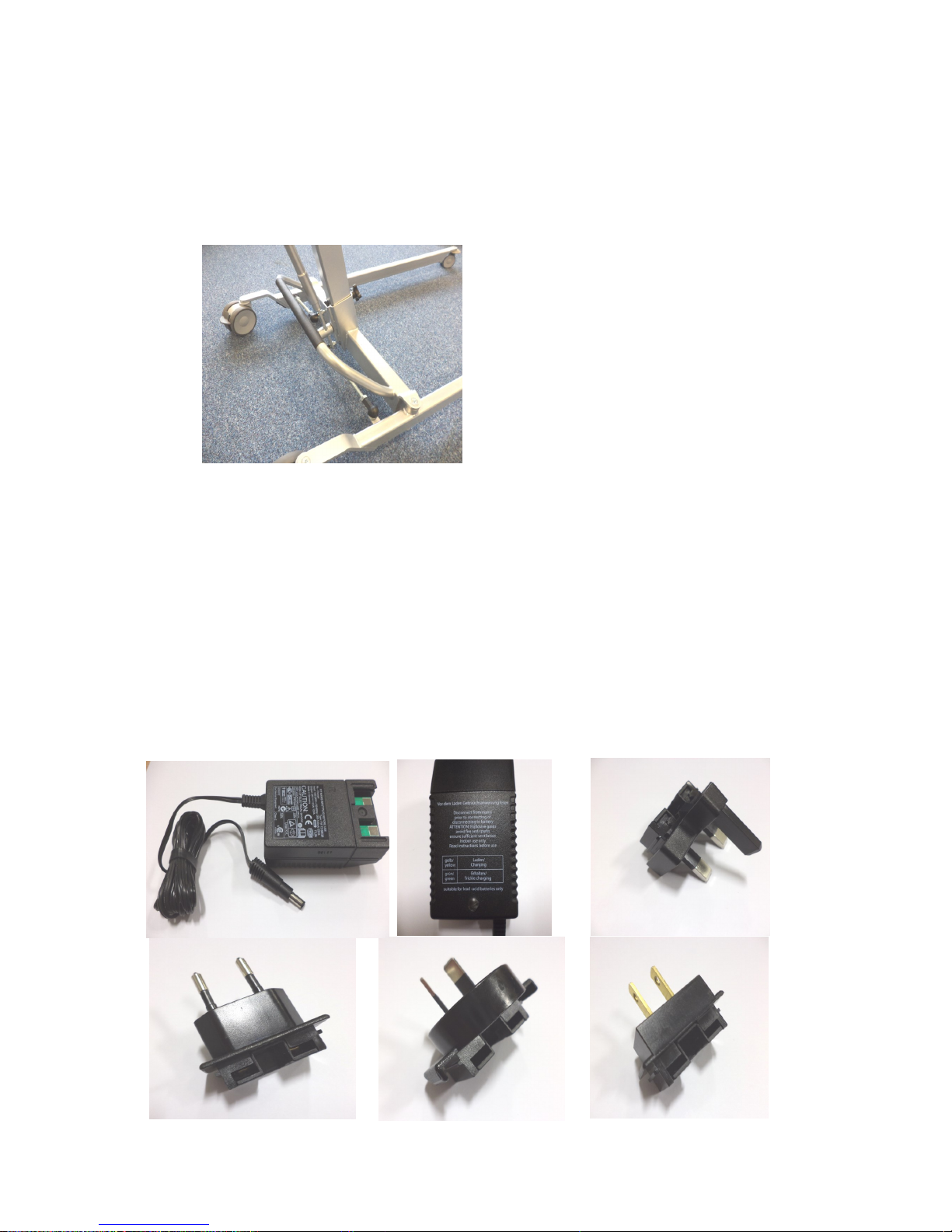
2.4 Electrical Charging lead on Mobile Hoists.
To recharge the battery pack, all E-Series mobile hoists are supplied with a
charger lead and a plug– in connection & conforms to CEE regulations. Different
plug-ins are available for export, as shown below.
Euro plug
Australian plug
USA & Japan
UK plug
Charger unit
© Prism Medical UK 2014
E Series User Manual Rev 03—Feb 2015 page 8
3.0 OPERATING INSTRUCTIONS
Freeway E-Series Mobile Hoist Range
Before use, you should familiarise yourself with use of the hoist the procedure for
opening / closing the leg sections and raising and lowering the hoist, including
emergency stop/lower and raise functions. Appropriate training in lifting and
handling procedures should be undergone by any person operating a mobile hoist
or sling, for their own and the clients safety and comfort. These instructions are
designed to cover the method of using of the Freeway mobile rather than good
manual handling practice.
3.1 To Alter the Leg Width
The leg adjustment is operated via the leg adjusting lever, positioned just below the
control box.
Hoisting manoeuvres can be completed with the legs in any position.
3.2 Positioning
1. Fit person to be lifted with a suitable sling. Instruction should be taken in the
fitting of slings to ensure maximum safety and comfort. A full assessment
should be carried out by a qualified person and carers should be trained in the
correct use.(See sling safety)
2. Select hoist leg position required. Position hoist near person to be lifted It is
recommended to position the hoist on a slight angle to prohibit legs hitting the mast /
actuator. Assuming you are lifting on a level surface “never“ use the brakes on the
hoist. This allows the hoist to align its self before lifting. Ensure ALL sling loops are
attached over the safety hooks on carry bar.
NOTE It is recommended to only use the brakes when carrying out lifts on / off the
floor OR for when the hoist is not in use & on charge.

© Prism Medical UK 2014
E Series User Manual Rev 03—Feb 2015 page 9
3.3 Raising & Lowering
1. To raise a person press handset button marked with upward facing arrow.
When the sling straps become taut before the lift is commenced, check the
straps are secure in position over the hooks of the carry bar before continuing
the lift. When the desired height has been reached, release button and hoist
will stop.
2. When moving a person, use the mast push handle and walk with the hoist.
NEVER pull or twist at arms length, this can cause injury to the carer.
3. When desired position is reached, position the hoist on a slight angle ready for
lowering.
4. To a lower person, press and hold handset button marked with downward
facing arrow and hoist will descend. When you have reached desired level,
simply release button and hoist will stop in that position.
3.4 Battery Charging
The battery will need to be charged on a regular basis.. A buzzer will sound when
the battery needs to be recharged. A yellow light will be displayed on the control
box to indicate that the battery is being recharged. A yellow light will also appear on
the charger.

© Prism Medical UK 2014
E Series User Manual Rev 03—Feb 2015 page 10
3.5 Handset
The E-series mobile hoist benefits
from the latest technology available
for use in patient hoists. The handset
operates 2 functions on the hoist unit.
They are:-
1. Raises the hoist
2. Lowers the hoist
The handset is attached to the
control box via a ‘curly’ flexible cable
that is secured in place with a
bayonet type fitting. The ‘curly’ flex is
designed to give the greatest number
of options for carer positioning
without having a trailing cable around
the patient.
The handset also incorporates a hook
which gives the carer flexibility whist
moving / positioning the patient.
Clear and easy to understand button
diagrams enable ease of use for the
care giver.
A green light will be displayed on the
control box when the handset is being
used.
1
2
3.6 Sling Guide
On the boom of every hoist there is a sling sizing guide for the Prism Range of
slings. This facilitates easy identification of the available slings in a multi use
environment.

© Prism Medical UK 2014
E Series User Manual Rev 03—Feb 2015 page 11
3.7 Sling Types
Universal Sling
Universal C/W Head Support
Dual Access Sling
Dual Access SRS Sling
The Prism range of slings are the result of many years of experience in assessment and
clinical expertise, combined with input from professional workers and users of slings. As a
result the range is a collection of subtly unique designs, combined with the use of modern
materials and technology which produces comfort, security, support and dignity for the
user, and aids correct application of the sling by the carer. The range of slings are equally
suitable for Mobile and Ceiling track hoists. All our slings are produced here in the UK and
carry the CE mark. They are manufactured to the highest standard under a rigorous quality
management system.
Contact Your Local Representative for more information
Hammock Sling
Comfort Recline

© Prism Medical UK 2014
E Series User Manual Rev 03—Feb 2015 page 12
4.0 SAFETY PRECAUTIONS
Please read and follow the safety precautions listed below. The operation and the
use of the Freeway E-series Mobile Hoist is straightforward. These basic safety precautions will help make lifting operations easy and trouble free.
ALWAYS carry out the DAILY CHECK LIST (next section) before using the hoist.
ALWAYS conduct a risk assessment to plan your lifting operations before
commencing.
ALWAYS read this manual and familiarise yourself with the operating control
and safety features of the hoist before lifting a patient.
ALWAYS check the sling is suitable for the particular patient and is of the
correct size and capacity.
ALWAYS fit the sling according to the instructions in the user manual.
ALWAYS check that the safe working load of the hoist is suitable for the weight of
the patient.
ALWAYS carry out lifting according to the instructions in the user manual.
ALWAYS apply the brakes when parking a hoist.
ALWAYS manoeuvre the hoist with the handle provided.
ALWAYS lower the patient to the lowest comfortable position before transfers.
NEVER push a loaded hoist at speeds which exceed a slow walking pace.
NEVER lift a patient whilst the brakes on the rear castor are in the on position (unless
lifting from the floor).
NEVER attempt to manoeuvre the lift by pushing on the mast, boom or patient.
NEVER use a sling unless it is recommended for use with the hoist.
NEVER push the hoist over uneven or rough ground, particularly if loaded.
NEVER attempt to push or pull a loaded hoist over a floor obstruction which the
castors are unable to ride over easily.
NEVER bump the hoist down steps, loaded or unloaded, this will damage the
castors.
NEVER allow water to enter the hand set or control box or use the hoist outside in
wet conditions.
Continued

© Prism Medical UK 2014
E Series User Manual Rev 03—Feb 2015 page 13
SAFETY PRECAUTIONS continued
NEVER use a sling which is frayed or damaged.
NEVER disconnect or bypass a control or safety feature because is seems
easier to operate the hoist.
NEVER force an operating or safety control. Forcing will only strain or damage
the hoist and may compromise safety.
NEVER use mobile hoists in a shower.
NEVER charge an electric lift in a bathroom or shower room.
NEVER dispose of the control unit in a fire as this contains the battery pack and
may cause an explosion. These need to be disposed under the W.E.E.E.
regulations. ( Waste Electrical & Electronic Equipment Regulations: 2006 )
YOUR hoist is for patient lifting. DO NOT use it, or allow it to be used, for any
other purpose.

© Prism Medical UK 2014
E Series User Manual Rev 03—Feb 2015 page 14
5.0 SAFETY CHECK LIST
The following checks are those recommended by Freeway and are supplementary to
requirements that may be applicable for current Lifting and Handling and other health and
Safety regulations such as The Lifting Operations and Lifting Equipment Regulations 1998
which may have additional requirements to those set out below
5.1 Daily Check List:
The following checks should be carried out daily before using the hoist:
Make sure the hoist moves freely on its castors
Make sure that leg opening and closing is functions correctly
Check the spreader bar for free movement in all directions and that it is
securely attached to the boom
Examine the sling hooks on the spreader bar for excessive wear
Raise and lower the hoist by operating the handset if the hoist makes a
bleeping sound DO NOT USE as it needs to be charged
Ensure the hoist is off charge before use and all leads are fully engaged into
their sockets
Make sure the mast is fully engaged and the locking nut is fully tightened
Examine slings for fraying or other damage. DO NOT use sling with fraying or
damage to the suspension straps or tears in the body of the sling
5.2 Warning Notes
Your Freeway hoist has been manufactured and tested to exceed BS EN
10535:2006
This does not mean that it can be used without care. ALL OPERATORS should
have read the operating instructions and appreciate this warning section.
1. ALL HOISTS are less stable on sloping surfaces. A 5-degree slope is the
maximum permitted and then only with great care.
2. ALL HOISTS are less stable when the load is at maximum height.
3. ALL HOISTS are less stable when the load is swinging.
4. ALL HOISTS are dangerous to the person being carried when used recklessly
or pushed at speed.

© Prism Medical UK 2014
E Series User Manual Rev 03—Feb 2015 page 15
6.0 TECHNICAL SPECIFICATION
6.1 Dimensions & Weights
6.2 Sound Levels—measured in dB A
E160 E180
Unloaded 47.1 43.5
Loaded 47.5 43.5
Model Specicaon
E160 E180
Maximum Weight capacity
160 180
Maximum Liing height
1650 1890
Minimum Liing Height
500 600
Internal Leg open
1150 1150
Internal Leg Closed
590 590
Overall Length
1190 1260
Spreader Bar at Max Reach
1040 1240
Reach at Max Height
520 560
Reach at Min Height
420 500
Max Reach
735 810
Turning Radius
1250 1350
Legs Open - External Width
1250 1350
Legs Open - Internal Width
1150 1150
LegsClosed - External Width
700 700
Legs Closed -Internal Width
590 590
Overall Height of Legs
97 123
Ground Clearance
35 50
Front Twin castors
75 75
Rear Braked Castors
100 100
Weights
Mast & Boom inc all xings
19 21
Base Assembly
14 18
Assembled Unit
33 39
( Dimensions in mm and weight in Kgs )

© Prism Medical UK 2014
E Series User Manual Rev 03—Feb 2015 page 16
TECHNICAL SPECIFICATION
6.3 Maximum lifting Height & leg width
6.4 Electrical detail
Electrical Specifications
Batteries – 2 x 12 volt rechargeable sealed lead acid
Battery capacity – 2.9 ampere hours
Charger Input - 230V ac 50/60Hz
Charger Output – 27.4/29.0V dc @ 0.8A
Electric shock protection-
Charger Class 2
Hoist Internal Power Source
Degree of Shock protection -
Charger Type B
Hoist Type B
The policy of Prism Medical UK is one of continual improvement and we reserve the
right to modify designs without notice.

© Prism Medical UK 2014
E Series User Manual Rev 03—Feb 2015 page 17
7.0 Fault Finding / Maintenance
7.1 Fault Finding
If the hoist will not operate:-
ENSURE THAT THE EMERGENCTY STOP BUTTON IS IN THE
OUT POSITION.
MAKE SURE THE CHARGING LEAD IS DISCONECTED FROM
THE MAINS POWER SUPPLY
CHECK THE HANDSET LEAD HAS NOT BEEN PULLED
FROM THE CONTROL BOX SOCKET OR WIRES DAMAGED
If the above checks prove unsuccessful, contact the service department
of your nearest FREEWAY APPROVED AGENT
7.2 Service / Maintenance
Any works performed on the E-series mobile hoist must be in
accordance with the specifications detailed in the test requirements of
BS 10535:2006.
You should also consider if the hoist requires servicing in accordance
with “LOLER REGULATIONS” (Lifting Operations and Lifting Equipment
Regulations 1998).
7.3 Cleaning, Disinfection and Sterilisation
The E-Series hoist has an anti-microbial coating. This does not replace
the need to clean and maintain the hoist unit.
Routine cleaning: the exterior of the hoist can be wiped over with a
damp cloth containing a mild soap solution.
Disinfection and Sterilisation: the exterior of the hoist should only
be, disinfected and sterilised using Isopropyl alcohol. Dampen a cloth
with isopropyl alcohol and wipe down the entire exterior of hoist.
DO NOT USE ABRASIVE MATERIALS
DO NOT IMMERSE THE HOIST UNIT.

© Prism Medical UK 2014
E Series User Manual Rev 03—Feb 2015 page 18
DECLARATION OF CONFORMITY
Manufacturers Name: Prism Medical UK Ltd
MHRA Registration No: CA 013248
Manufacturers Address: Units 1-4, Tir Llwyd Industrial Estate,
Kinmel Bay, Conwy,
LL18 5JA, UK
Tel +44 (0) 844 980 2296
Fax +44 (0) 844 980 2297
Declares that the manufactured product: Product Name: Prism Medical UK—Mobile Hoists
Model Number (S): E160 & E180
Product Options: 160 Kg & 180Kg
Conforms to the following European Union Council Directives:-
Directive 93/42/EEC and all amendments up to Directive 2007/47/EC
Classification Class 1, Low Risk Medical Device
Tested in accordance with BS EN ISO 10535:2006 & IEC 60601 3rd Edition
Directive 89/336/EEC for Electromagnetic Compatibility
Supplementary Information:
The undersigned declares the product herewith complies with the requirements set out
above and carries the CE mark accordingly.
The Technical Construction File required by this directive is maintained by the
manufacturer as detailed above.
Signed: Date: 14th November 2014
Craig Wright, Manufacturing Director

© Prism Medical UK 2014
E Series User Manual Rev 03—Feb 2015 page 19
8.0 Test Certificate & Guarantee
TEST CERTIFICATE E-Series Mobile Hoist
Safe Working Load: 160Kgs 180Kgs
Model: E-160 E-180
Serial No: ……………………………………………………………………..
Date of Test: …………………………………………………………………..
This Test Certificate confirms that the above numbered hoist has been fully tested in
accordance with the tests specified in BS EN 10535 and has conformed fully therewith.
Signature of Tester ……………………………………………………
Guarantee
This guarantee does not affect or in any way limit your Statutory Rights
1) Prism Medical UK guarantees the E160 /E180, supplied as new, against failure within the period
of twenty four months from the date of purchase by virtue of defects in material or
workmanship.
2) The liability of Prism Medical UK under terms of this guarantee shall be limited to the
replacement or the defective part (s) to the sales distributor, dealer, agent, person or entity which
purchased the equipment from Prism Medical UK. In no event shall Prism Medical UK incur
liability for any consequential or unforeseeable losses.
3) This equipment guarantee shall be void if the equipment is not serviced by Prism Medical UK or
its authorised agents, in accordance with manufacturer’s recommendations, or if any
unauthorised persons carry out work on the equipment.
4) This guarantee does not apply to failure attributable to normal wear and tear, damage by natural
forces, user neglect or misuse or to deliberate destruction.
Exemptions: Batteries will be guaranteed for a period of 90-days after original purchase.

© Prism Medical UK 2014
E Series User Manual Rev 03—Feb 2015 page 20
9.0 Service Record History
9.1 Initial Information
PURCHASE INFORMATION:
Product Name: Freeway E-Series Mobile Hoist Model: E160 E180
Date of Purchase: __________________ Serial#: ________________________
Purchased From: ____________________________________________________
Address: ___________________________________________________________
City: _____________________________ Postal Code: __________________
Telephone No: __________________________
Comments:
Complete the following section on Purchase and Service Information as soon
as this equipment is supplied.
Use the service record history to record to any completed service and repairs.
Ensure that the service record is signed and dated each time it is used.
Be sure to have this piece of equipment serviced on a regular basis (6 monthly
where LOLER applies).
SERVICE INFORMATION:
Contact the following company for service:
Company: __________________________________________________________
Address: __________________________________________________________
City: ______________________________ Postal Code: _______________
Telephone No: __________________________
Comments:

© Prism Medical UK 2014
E Series User Manual Rev 03—Feb 2015 page 21
9.2 Service Record History
Complete this section after each service, repair inspection and/or maintenance. Photocopy additional pages
as required.
Service Type: □ Periodic Inspection □ Monthly Inspection □ 6 Month Inspection □ Repair □ Yearly Inspection □ Other:_________
Completed By: _________________________ _____________________________
Printed Name Signature
Company: _____________________________________________________________
Remarks & Action Taken:
Date: _______________________ Time: ________________________

© Prism Medical UK 2014
E Series User Manual Rev 03—Feb 2015 page 22
Service Record History
Complete this section after each service, repair inspection and/or maintenance. Photocopy additional pages
as required.
Service Type: □ Periodic Inspection □ Monthly Inspection □ 6 Month Inspection □ Repair □ Yearly Inspection □ Other:_________
Completed By: _________________________ _____________________________
Printed Name Signature
Company: _____________________________________________________________
Remarks & Action Taken:
Date: _______________________ Time: ________________________
Service Type: □ Periodic Inspection □ Monthly Inspection □ 6 Month Inspection □ Repair □ Yearly Inspection □ Other:_________
Completed By: _________________________ _____________________________
Printed Name Signature
Company: _____________________________________________________________
Remarks & Action Taken:
Date: _______________________ Time: ________________________
Service Type: □ Periodic Inspection □ Monthly Inspection □ 6 Month Inspection □ Repair □ Yearly Inspection □ Other:_________
Completed By: _________________________ _____________________________
Printed Name Signature
Company: _____________________________________________________________
Remarks & Action Taken:
Date: _______________________ Time: ________________________
Service Type: □ Periodic Inspection □ Monthly Inspection □ 6 Month Inspection □ Repair □ Yearly Inspection □ Other:_________
Completed By: _________________________ _____________________________
Printed Name Signature
Company: _____________________________________________________________
Remarks & Action Taken:
Date: _______________________ Time: ________________________
Service Type: □ Periodic Inspection □ Monthly Inspection □ 6 Month Inspection □ Repair □ Yearly Inspection □ Other:_________
Completed By: _________________________ _____________________________
Printed Name Signature
Company: _____________________________________________________________
Remarks & Action Taken:
Date: _______________________ Time: ________________________
Service Type: □ Periodic Inspection □ Monthly Inspection □ 6 Month Inspection □ Repair □ Yearly Inspection □ Other:_________
Completed By: _________________________ _____________________________
Printed Name Signature
Company: _____________________________________________________________
Remarks & Action Taken:
Date: _______________________ Time: ________________________

© Prism Medical UK 2014
E Series User Manual Rev 03—Feb 2015 page 23
Service Record History
Complete this section after each service, repair inspection and/or maintenance. Photocopy additional pages
as required.
Service Type: □ Periodic Inspection □ Monthly Inspection □ 6 Month Inspection □ Repair □ Yearly Inspection □ Other:_________
Completed By: _________________________ _____________________________
Printed Name Signature
Company: _____________________________________________________________
Remarks & Action Taken:
Date: _______________________ Time: ________________________
Service Type: □ Periodic Inspection □ Monthly Inspection □ 6 Month Inspection □ Repair □ Yearly Inspection □ Other:_________
Completed By: _________________________ _____________________________
Printed Name Signature
Company: _____________________________________________________________
Remarks & Action Taken:
Date: _______________________ Time: ________________________
Service Type: □ Periodic Inspection □ Monthly Inspection □ 6 Month Inspection □ Repair □ Yearly Inspection □ Other:_________
Completed By: _________________________ _____________________________
Printed Name Signature
Company: _____________________________________________________________
Remarks & Action Taken:
Date: _______________________ Time: ________________________
Service Type: □ Periodic Inspection □ Monthly Inspection □ 6 Month Inspection □ Repair □ Yearly Inspection □ Other:_________
Completed By: _________________________ _____________________________
Printed Name Signature
Company: _____________________________________________________________
Remarks & Action Taken:
Date: _______________________ Time: ________________________
Service Type: □ Periodic Inspection □ Monthly Inspection □ 6 Month Inspection □ Repair □ Yearly Inspection □ Other:_________
Completed By: _________________________ _____________________________
Printed Name Signature
Company: _____________________________________________________________
Remarks & Action Taken:
Date: _______________________ Time: ________________________
Service Type: □ Periodic Inspection □ Monthly Inspection □ 6 Month Inspection □ Repair □ Yearly Inspection □ Other:_________
Completed By: _________________________ _____________________________
Printed Name Signature
Company: _____________________________________________________________
Remarks & Action Taken:
Date: _______________________ Time: ________________________

© Prism Medical UK 2014
E Series User Manual Rev 03—Feb 2015 page 24
NOTES
Disclaimer
While every effort has been made to ensure the accuracy of information
contained in this user manual, no liability can be accepted by Prism Medical for
any errors or omissions. Prism Medical operates a policy of continuous
improvement. Specifications and other data are subject to change without notice.
Unit 1 Tir Llwyd Industrial Estate, St Asaph Avenue, Kinmel Bay, Nr Rhyl, Conwy, LL18 5JA
Info@prismmedical.co.uk Tel +44 (0)844 980 2296 www.prismmedical.co.uk
 Loading...