

FREEWAY 5B5-01 Installation Instructions Manual
ModelNo:-
5B5-
50.0
34.0
15.6
15°
15°
25.8
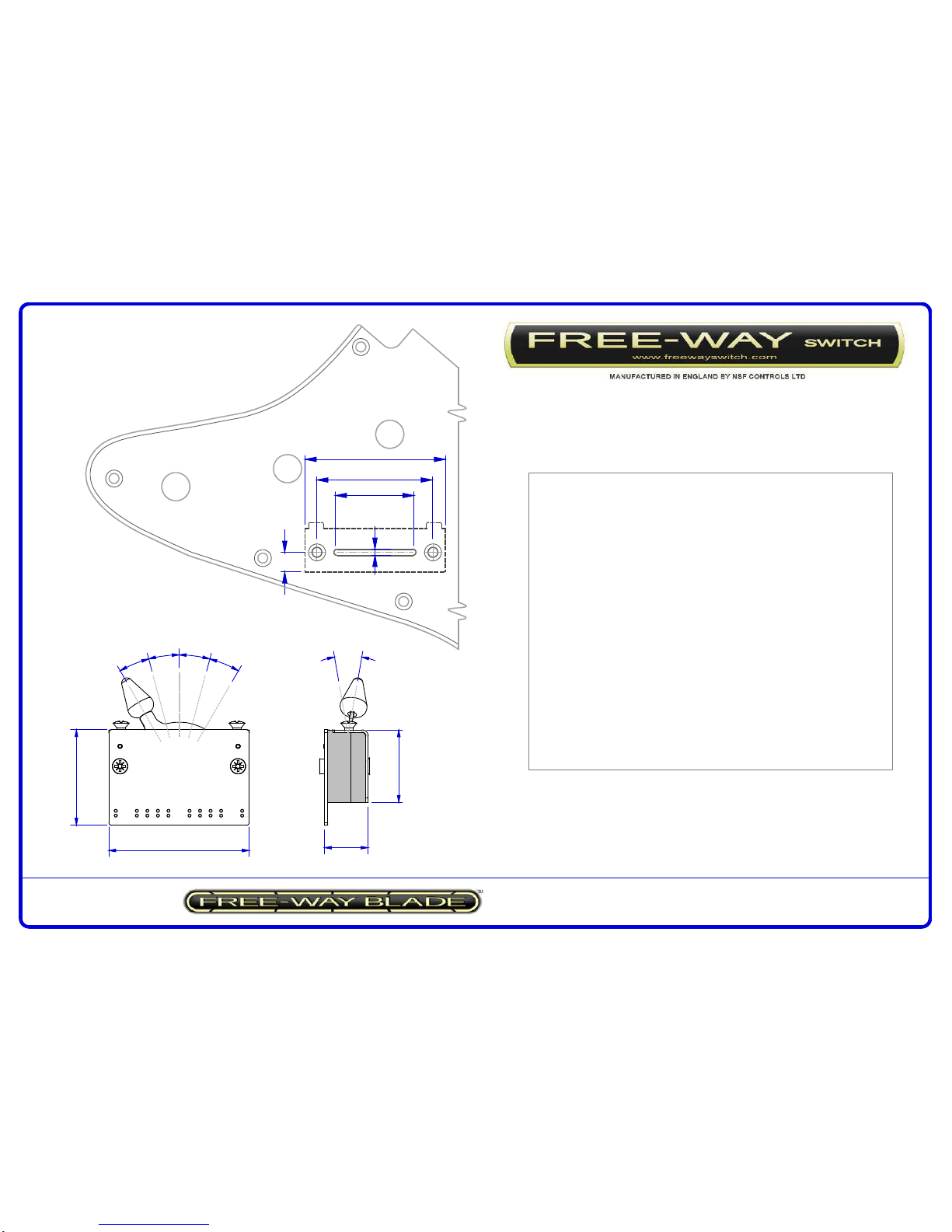
Pick Guard Thickness assumedto be 2.3mm
Mounting Holes should be Ø3.5 Csk (tosuit M3 x 10mm Csk Screws provided)
Mounting Hole Ctrsare tolerantto a range between 41.0 and 41.4mm
Minimum Lever Slot Dimensions to Pickguard: 28.0 x 2.0mm
A small chamfer maybe addedto theexternal edgesof a narrower Lever slot to adapt it.
This guide requiresand assumes proper competencies with regard to electrical and practical work,
safety and the correctuse ofany equipmentreferenced here. Always take precautions to protect
the guitar, yourself and others. Ensure that anyaccociated products are installed in fullaccordance
with themanufacturers instructions.
Check that the Free-Way BladeSwitch will fit - refer to dimensionalinformation provided
Use22AWGWire,stripinsulationback5mm,twiststrandsandlocateintoterminalholes.
Makeany'daisy-chain'linksandlocatetheseintooneoftheterminalholepairs.
Solderusingmulti-coresolder.Ensuresolderjointiscleanandflowsaboutterminalpad.
Avoidexcessivesolder,avoidcontactinganyotherpartoftheswitchwiththesolderingiron
.
Theswitchmetalworkisstainlesssteelandcannotbesoldered,norshouldthisbeattempted.
15°
15°
41.2 Ctrs
2.0
7.0
Notes:-
Avoid using mounting screws which are any longer than the ones supplied
Switch Tip to suit 3.5mm x 1.0mm (0.138" x 0.039") lever stem.
General Installation Instructions
28.0
50.0
Lever Slot & MountingHole Dimensions
20°
Cavity Depth34mm Min.
5B5GeneralInstallation: LastUpdated Jul 2018
©Free-Way2018
5B5-01
BGBTBH
MH
ABGDOPNH
NG
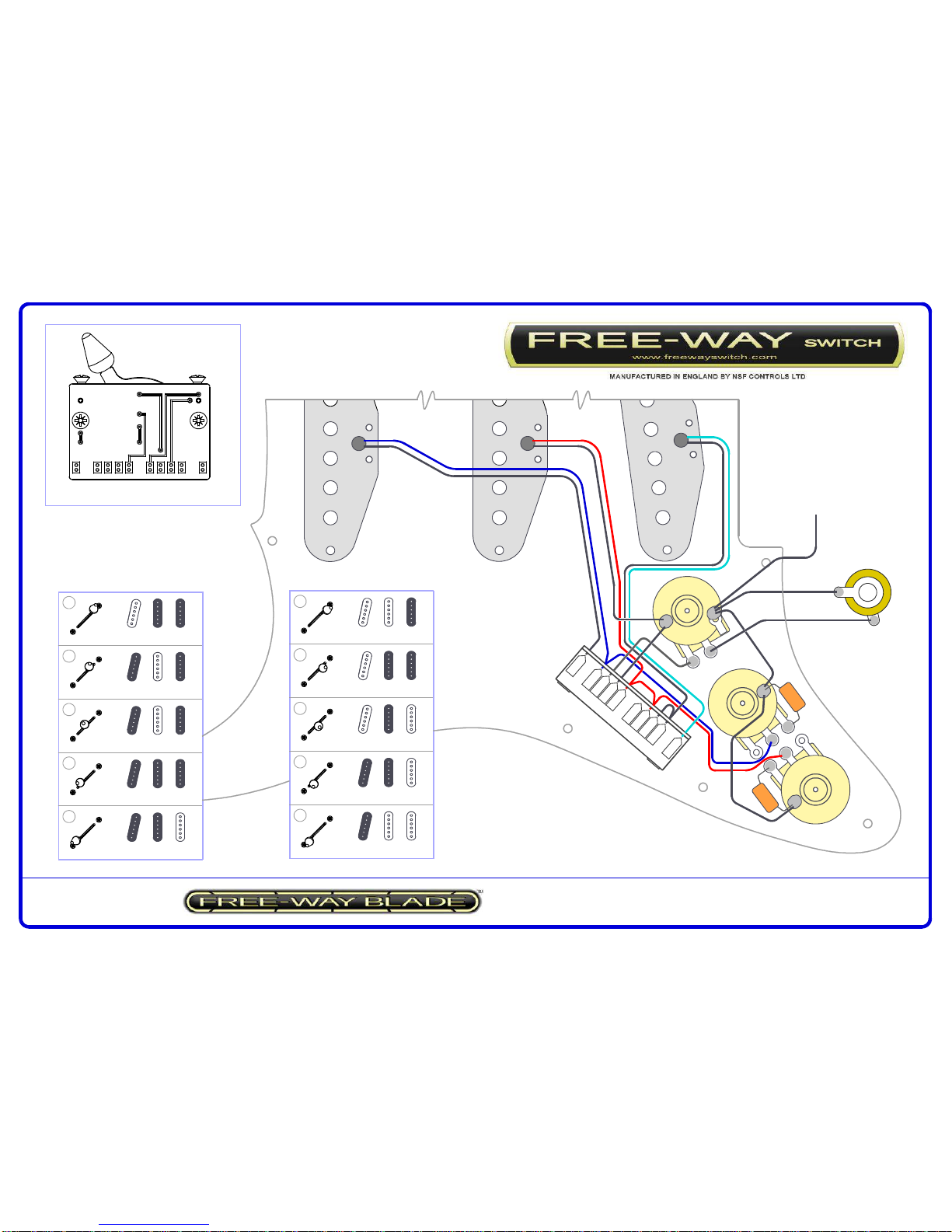
FREE-WAY
SSS Parallel Series Scheme A 1V/2T
Model No:-
5B5-01
5
N
M
B
4
3
2
1
IN PARALLEL
10
9
8
7
6
IN SERIES
NH
OP
GD
B
A
MH
BG
BT
BH
NG
TIP
RING
B + M
M + N
IN SERIES
IN PARALLEL
IN SERIES
FRONTVIEWOFPICKUPSANDSWITCH
FRONTVIEWOFPICKUPSANDSWITCH
REVERSEVIEWOFPICKUPS,SWITCHANDPOTENTIOMETERS.
TN
TM
V
NECK
MIDDLE BRIDGE
GROUND WIRES TO CAVITY
SHIELD& SPRING CLAW
Switch metalwork is assumed tobe groundedby shieldingon
reverse of scratch-plate which is assumed groundedvia thepotentiometers
Refer to Free-Way Blade Installation Instructions
N
o
t
e
:
t
e
r
m
i
n
a
l
A
i
s
n
o
t
u
s
e
d
.
SchemeNo B001: LastUpdated Jul 2018
Hot
Grd
Hot
Grd
Hot
Grd
©Free-Way2018
5B5-01
BGBTBH
MH
ABGDOPNH
NG
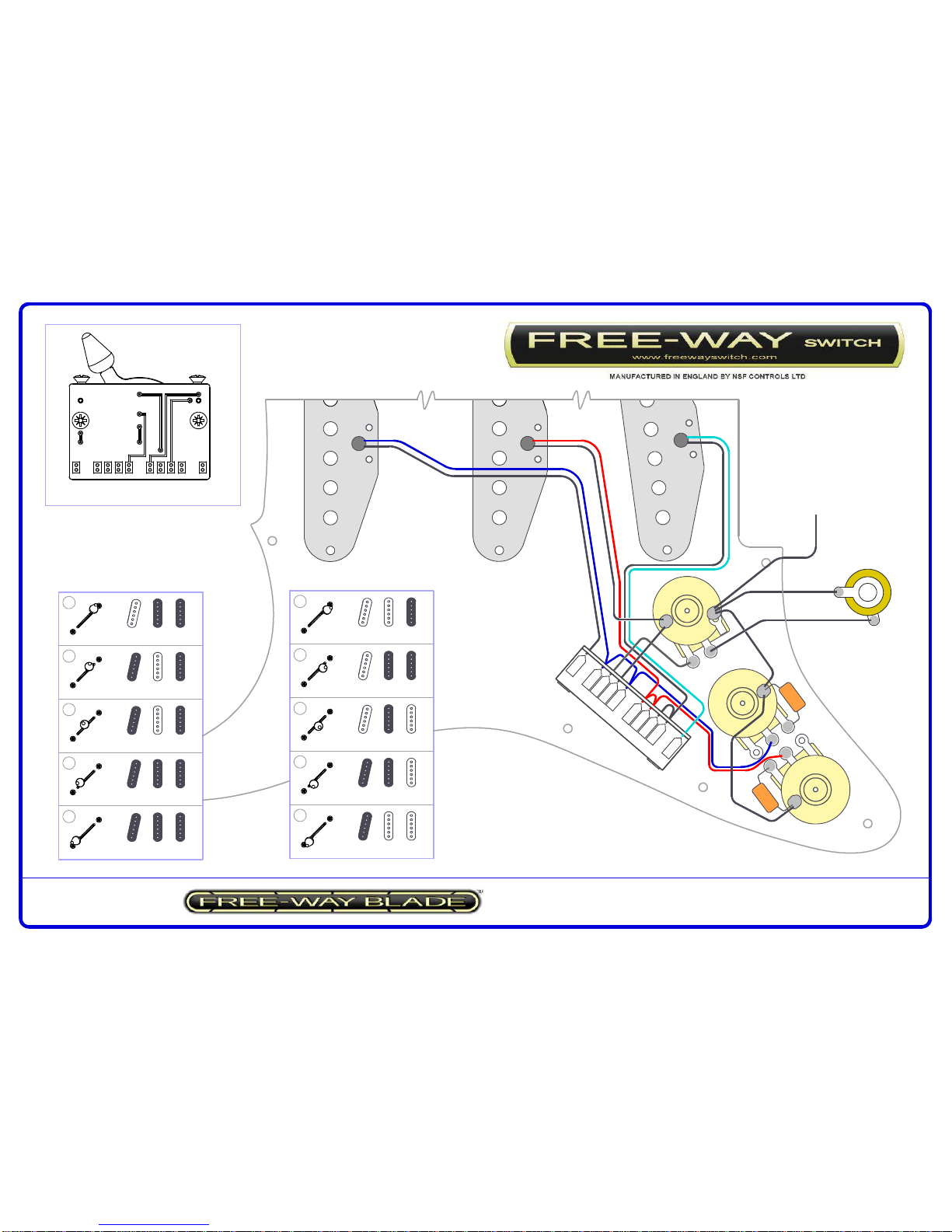
FREE-WAY
SSS Parallel Series Scheme B 1V/2T
Model No:-
5
N
M
B + M
B
4
3
2
1
M + N
IN SERIES
IN PARALLEL
10
9
8
7
6
IN PARALLEL
IN SERIES
IN SERIES
NH
OP
GD
B
A
MH
BG
BT
BH
NG
TIP
RING
FRONTVIEWOFPICKUPSANDSWITCH
FRONTVIEWOFPICKUPSANDSWITCH
REVERSEVIEWOFPICKUPS,SWITCHANDPOTENTIOMETERS.
TN
TM
V
NECK
MIDDLE BRIDGE
GROUND WIRES TO CAVITY
SHIELD& SPRING CLAW
Switch metalwork is assumed tobe groundedby shieldingon
reverse of scratch-plate which is assumed groundedvia thepotentiometers
Refer to Free-Way Blade Installation Instructions
5B5-01
Hot
Grd
Hot
Grd
Hot
Grd
SchemeNo B003: LastUpdated Jul 2018
©Free-Way2018
 Loading...