

Page 1
ZumLink™ Z9-P / Z9-PE
User Manual
Part Number: LUM0076AA
Revision: Jul-2017
Page 2

Safety Information
The products described in this manual can fail in a variety of modes due to misuse, age, or malfunction and is not
designed or intended for used in systems requiring fail-safe performance, including life safety systems. Systems
with the products must be designed to prevent personal injury and property damage during product operation
and in the event of product failure.
Warning! Do not remove or insert any of the cables while the unit is powered on unless the area is
known to be free of ignition concentrations of flammable gasses or vapors.
Warranty Information
FreeWave Technologies, Inc. warrants the FreeWave® ZumLink Z9-P / Z9-PE (Product) that you have purchased
against defects in materials and manufacturing for a period of two years from the date of shipment, depending on
model number. In the event of a Product failure due to materials or workmanship, FreeWave will, at its discretion,
repair or replace the Product. For evaluation of Warranty coverage, return the Product to FreeWave upon
receiving a Return Material Authorization (RMA). The replacement product will remain under warranty for 90
days or the remainder of the original product warranty period, whichever is longer.
IN NO EVENT WILL FREEWAVE TECHNOLOGIES, INC., ITS SUPPLIERS, OR ITS LICENSORS BE LIABLE FOR ANY DAMAGES ARISING
FROM THE USE OF OR INABILITY TO USE THIS PRODUCT. THIS INCLUDES BUSINESS INTERRUPTION, LOSS OF BUSINESS
INFORMATION, INABILITY TO ACCESS OR SEND COMMUNICATION OR DATA, PERSONAL INJURY OR DAMAGE, OR OTHER LOSS
WHICH MAY ARISE FROM THE USE OF THIS PRODUCT. THE WARRANTY IS EXCLUSIVE AND ALL OTHER WARRANTIES EXPRESS
OR IMPLIED, INCLUDING BUT NOT LIMITED TO ANY WARRANTIES OF MERCHANTABILITY OR FITNESS FOR A PARTICULAR USE
ARE EXPRESSLY DISCLAIMED.
FreeWave’s Warranty does not apply in the following circumstances:
1. If Product repair, adjustments, or parts replacements are required due to accident, neglect, or undue
physical, electrical, or electromagnetic stress.
2. If Product is used outside of FreeWave specifications as stated in the Product's data sheet.
3. If Product has been modified, repaired, or altered by Customer unless FreeWave specifically authorized
such alterations in each instance in writing.
Warning! The Z9-P is sold as a multi-board solution, assembled at the FreeWave factory.
Separation of the individual boards voids the FreeWave warranty.
Warning! The ZumLink Z9-PE is sold as a fully enclosed device, assembled at the FreeWave
factory. Opening the ZumLink Z9-PE device voids the FreeWave warranty.
FreeWave Technologies, Inc.
5395 Pearl Parkway, Suite 100
Toll Free: 1.866.923.6168
Copyright © 2017 by FreeWave Technologies, Inc.
All rights reserved.
Boulder, CO 80301
303.381.9200
Fax: 303.786.9948
www.freewave.com
Page 2 of 171 LUM0076AA Rev Jul-2017
This document is the property of FreeWave Technologies, Inc. and contains proprietary information owned by
FreeWave. This document cannot be reproduced in whole or in part by any means without written permission from
FreeWave Technologies, Inc.
Page 3

ZumLink™ Z9-P / Z9-PE: User Manual
Table of Contents
Preface 5
1. ZumLink Overview 7
2. Equipment 8
2.1. Included Equipment 8
2.1.1. User-supplied Equipment 8
3. Installation 9
3.1. Powering the ZumLink Z9-P / Z9-PE 9
3.2. Connections and Installation 10
3.2.1. Z9-P Connections 10
3.2.2. Z9-PE Connections 10
4. Drag and Drop Configuration 13
5. CLI Configuration 20
5.1. Connect the ZumLink Z9-P / Z9-PE to the Computer 21
5.2. Installing the ZumLink Z9-P / Z9-PE Driver 23
5.3. Tera Term Activation & ZumLink Z9-P / Z9-PE Setup 28
6. Creating a Basic ZumLink Gateway and Endpoint Network 33
7. Firmware Upgrade - Drag and Drop 35
7.1. Download the Upgrade File 36
7.2. Install the Upgrade File 39
8. Firmware Upgrade - Web Interface 43
8.1. Download the Upgrade File 44
8.2. Setup the Computer IP Address Configuration 47
8.3. Install the Upgrade File using the Web Interface 51
9. Ports 56
9.1. Z9-P Ports 56
9.2. Z9-PE Ports 57
9.3. Serial and Ethernet Port Details 57
10. Mounting the ZumLink 59
10.1. Z9-P Mounting 60
10.1.1. Included Equipment 60
10.2. Z9-PE Mounting 61
10.2.1. Included Equipment 61
10.3. Removing the ZumLink from the DIN Rail 62
11. Approved Antennas 63
11.1. 900MHz Antennas 63
11.1.1. 900MHz Omni-Directional Antennas 63
11.1.2. 900MHz Directional Antennas 64
11.1.3. Alternative Antennas 64
LUM0076AA Rev Jul-2017 Page 3 of 171
This document is the property of FreeWave Technologies, Inc. and contains proprietary information owned by
FreeWave. This document cannot be reproduced in whole or in part by any means without written permission from
FreeWave Technologies, Inc.
Page 4

12. ZumLink Z9-P / Z9-PE Web Interface 65
12.1. File Upload window 66
12.2. Help window 68
12.3. Home window 69
12.4. System Info window 70
12.5. User Data - Drag and Drop window 72
13. ZumLink Z9-P / Z9-PE Settings and Descriptions 73
Com1 or Com2 74
config 82
dataPath 84
date 87
encryption 90
localDiagnostics 93
network 101
networkStats 106
ntp 109
radioSettings 111
radioSettingsHelpers 129
services 130
SNMP 131
system 135
systemInfo 138
14. Release Notes 144
14.1. Version 1.0.4.2 144
14.2. Version 1.0.4.1 145
14.3. Version 1.0.3.2 (Initial Release) 146
15. Available Accessories 147
15.1. Z9-P and Z9-PE Accessories 147
15.2. Z9-P Only Accessories 148
15.3. Z9-PE Only Accessories 148
Appendix A: Technical Specifications - 900MHz 149
Appendix B: Mechanical Drawing - Z9-P 154
Appendix C: Mechanical Drawing - Z9-PE 156
Appendix D: LEDs 158
Normal Operation 158
COM LEDs 159
Ethernet LEDs 160
Appendix E: ZumLink Z9-P / Z9-PE Files and Descriptions 161
Appendix F: ZumLink MIB 163
Appendix G: FreeWave Legal Information 167
Page 4 of 171 LUM0076AA Rev Jul-2017
This document is the property of FreeWave Technologies, Inc. and contains proprietary information owned by
FreeWave. This document cannot be reproduced in whole or in part by any means without written permission from
FreeWave Technologies, Inc.
Page 5
ZumLink™ Z9-P / Z9-PE: User Manual
Document Description
FreeWave
Part Number
User Manual The User Manual provides detailed information about setup,
drag-and-drop configuration, and safety information for the
ZumLink Z9-P / Z9-PE.
LUM0076AA
Quick Start Guide The Quick Start Guide provides the out-of-the-box setup of
the ZumLink.
Z9-P
Z9-PE
QSG0046AA
QSG0029AA
Preface
Contact FreeWave Technical Support
For up-to-date troubleshooting information, check the Support page at www.freewave.com.
FreeWave provides technical support Monday through Friday, 8:00 AM to 5:00 PM Mountain
Time (GMT -7).
l Call toll-free at 1.866.923.6168.
l In Colorado, call 303.381.9200.
l Contact us through e-mail at moreinfo@freewave.com.
Other ZumLink Z9-P / Z9-PE Information
Use the FreeWave http://support.freewave.com/ website to download the latest version of
these documents.
Registration is required to use this login.
LUM0076AA Rev Jul-2017 Page 5 of 171
This document is the property of FreeWave Technologies, Inc. and contains proprietary information owned by
FreeWave. This document cannot be reproduced in whole or in part by any means without written permission from
FreeWave Technologies, Inc.
Page 6
Preface
Document Styles
This document uses these styles:
l Parameter setting text appears as: [Page=radioSettings]
l File names appear as: configuration.cfg.
l File paths appear as: C:\Program Files (x86)\FreeWave Technologies.
l User-entered text appears as: xxxxxxxxx.
Caution: Indicates a situation that MAY cause damage to personnel, the radio, data, or
network.
Example: Provides example information of the related text.
FREEWAVE Recommends: Identifies FreeWave recommendation information.
Important!: Provides crucial information relevant to the text or procedure.
Note: Emphasis of specific information relevant to the text or procedure.
Provides time saving or informative suggestions about using the product.
Warning! Indicates a situation that WILL cause damage to personnel, the radio, data, or
network.
Printing this Document
This document is set to print double-sided with a front cover and a back cover. Viewing this
document online with a PDF viewer, may show pages intentionally left blank to accommodate the
double-sided printing.
Documentation Feedback
Send comments or questions about this document's content to techpubs@freewave.com. In the
email, include the title of the document or the document's part number and revision letter (found in
the footer).
Page 6 of 171 LUM0076AA Rev Jul-2017
This document is the property of FreeWave Technologies, Inc. and contains proprietary information owned by
FreeWave. This document cannot be reproduced in whole or in part by any means without written permission from
FreeWave Technologies, Inc.
Page 7

ZumLink™ Z9-P / Z9-PE: User Manual
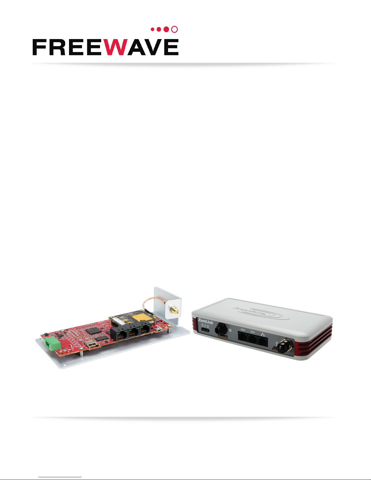
1. ZumLink Overview
Thank you for purchasing the FreeWave ZumLink™ Z9-P / Z9-PE.
l The ZumLInk Z9-P is a 900 MHz Ethernet radio attached to a mounting plate.
l The ZumLink Z9-PE is a 900MHz enclosed Ethernet radio.
ZumLink is the latest generation of radios offered by FreeWave which consists of enclosed and
board level radios.
The ZumLink Z9-P / Z9-PE 900MHz Series:
l Operates in the unlicensed 900MHz ISM band (902-928 MHz).
l Provides a maximum of 30dBm transmit output power.
l Is FCC compliant as both a Frequency Hopping Spread Spectrum (FHSS) and a Digital
Modulating (DM) radio.
Note: The frequency hopping capability is available at all bandwidths and the single channel
operation is available for bandwidths of at least 500 kHz.
The ZumLink Z9-P / Z9-PE has one Ethernet port, two serial ports, and one micro USB port.
LUM0076AA Rev Jul-2017 Page 7 of 171
This document is the property of FreeWave Technologies, Inc. and contains proprietary information owned by
FreeWave. This document cannot be reproduced in whole or in part by any means without written permission from
FreeWave Technologies, Inc.
Page 8
ZumLink™ Z9-P / Z9-PE: User Manual
Included Equipment
Qty Description
1 ZumLink Z9-P / Z9-PE wireless device
1 Power Cable w/ flying leads
l Z9-P FreeWave Part Number: ASC2402PT
l Z9-PE FreeWave Part Number: ASC0003ZL
1 Quick Start Guide
2. Equipment
2.1. Included Equipment
This is the equipment included with the ZumLink:
Note: See the Available Accessories (on page 147).
2.1.1. User-supplied Equipment
l USB to micro-USB cable
l Ethernet cable
l FCC approved antenna for the ZumLink Z9-P / Z9-PE**.
Note: **See Approved Antennas (on page 63) for detailed information.
Approved antennas can be purchased directly from FreeWave.
LUM0076AA Rev Jul-2017 Page 8 of 171
This document is the property of FreeWave Technologies, Inc. and contains proprietary information owned by
FreeWave. This document cannot be reproduced in whole or in part by any means without written permission from
FreeWave Technologies, Inc.
Page 9
ZumLink™ Z9-P / Z9-PE: User Manual
3. Installation
l Powering the ZumLink Z9-P / Z9-PE (on page 9)
l Connections and Installation (on page 10)
3.1. Powering the ZumLink Z9-P / Z9-PE
l The ZumLink Z9-P / Z9-PE is approved to operate with an input voltage range of +6 to
+30VDC.
l See the Technical Specifications - 900MHz (on page 149) for additional information.
FREEWAVE Recommends: All input power supply wires should be at least 20AWG wires.
A dedicated power supply line is preferred.
The power supply used MUST provide more current than the amount of current drain listed in the
specifications for the product and voltage. (at least 270 mA at 12V)
Warning! Use electrostatic discharge (ESD) protectors to protect the radio from electric shock
and provide filtered conditioned power with over-voltage protection.
LUM0076AA Rev Jul-2017 Page 9 of 171
This document is the property of FreeWave Technologies, Inc. and contains proprietary information owned by
FreeWave. This document cannot be reproduced in whole or in part by any means without written permission from
FreeWave Technologies, Inc.
Page 10

3. Installation
3.2. Connections and Installation
Note: The images in this procedure are for Windows® 7 and/or Firefox®.
The dialog boxes and windows appear differently on each computer.
3.2.1. Z9-P Connections
3.2.2. Z9-PE Connections
Figure 1: Z9-P Connections
Figure 2: Z9-PE Connections
Page 10 of 171 LUM0076AA Rev Jul-2017
This document is the property of FreeWave Technologies, Inc. and contains proprietary information owned by
FreeWave. This document cannot be reproduced in whole or in part by any means without written permission from
FreeWave Technologies, Inc.
Page 11
ZumLink™ Z9-P / Z9-PE: User Manual
1. Install an FCC-approved antenna.
2. Connect the antenna feed line to the ZumLink.
Warning! Only FCC approved antennas may be used. See Approved Antennas (on
page 63). The antenna must be professionally installed on a fixed, mounted, and
permanent outdoor structure to satisfy RF exposure requirements.
Any antenna placed outdoors must be properly grounded.
Use extreme caution when installing antennas and follow all instructions included with
the antenna.
If installing a directional antenna, preset the antenna’s direction appropriately.
3. Connect the ZumLink to a power supply.
The ZumLink requires a continuous +6 to +30VDC power source that can supply at least
0.8 Amps.
Caution: All input power supply wires should be at least 20AWG wires.
A dedicated power supply line is preferred.
The power supply used MUST provide more current than the amount of current drain
listed in the specifications for the product and voltage.
The LED lights blink to show startup.
Note: See LEDs (on page 158) for more information.
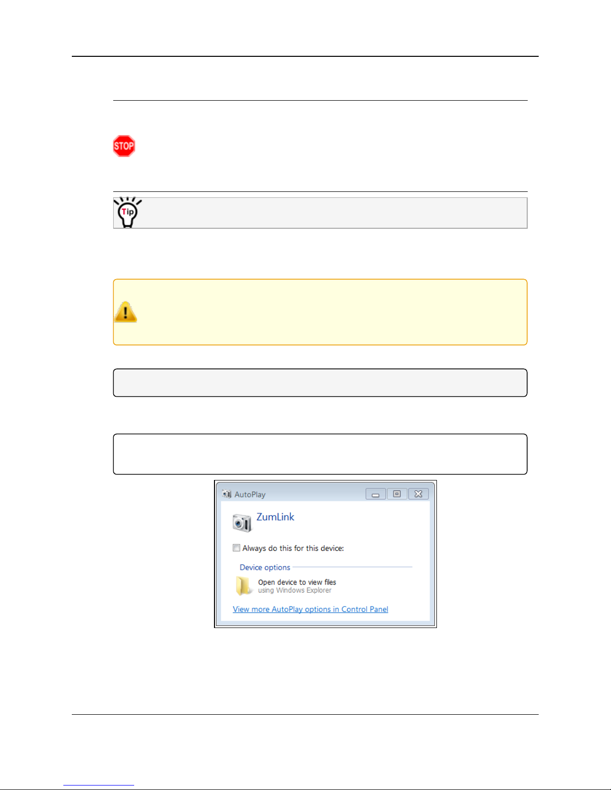
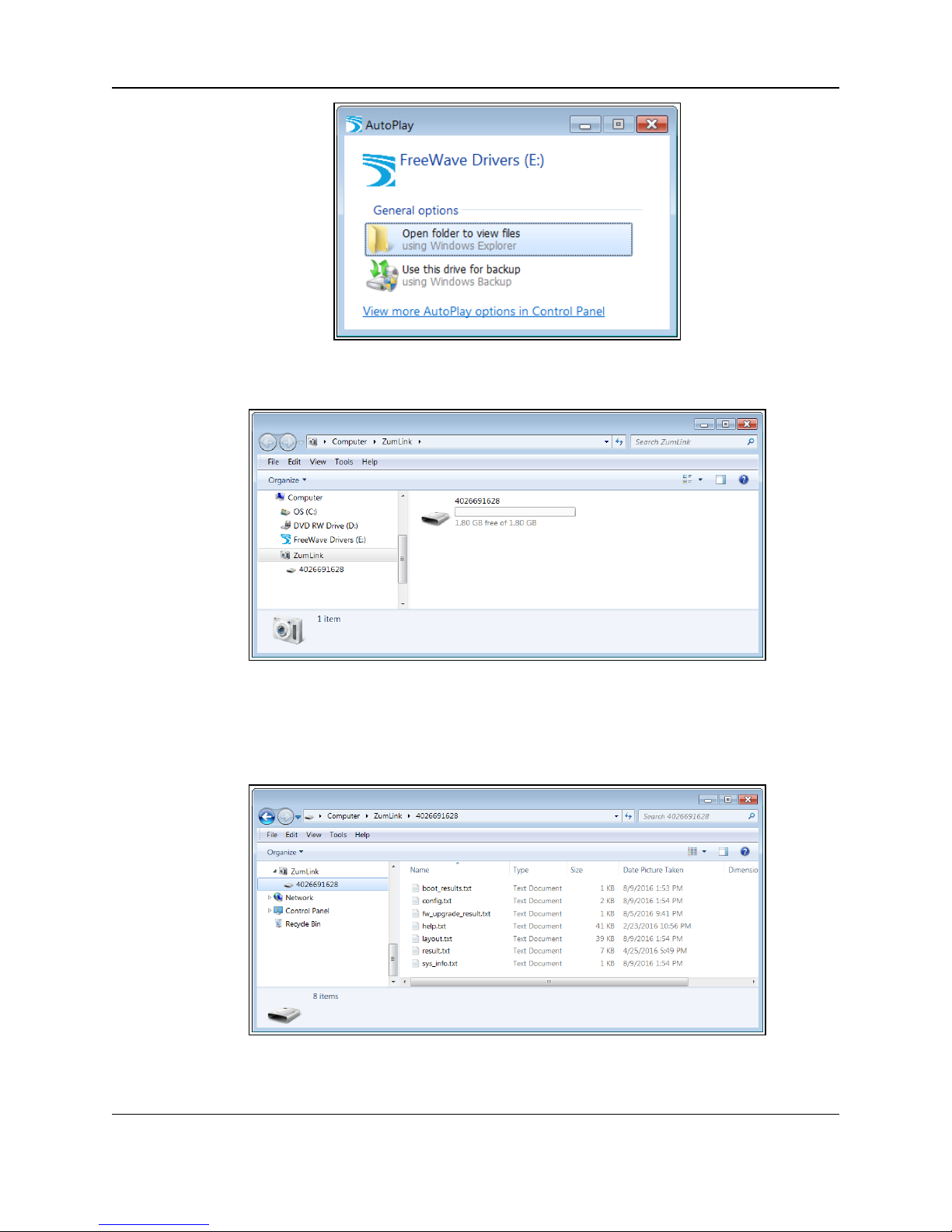
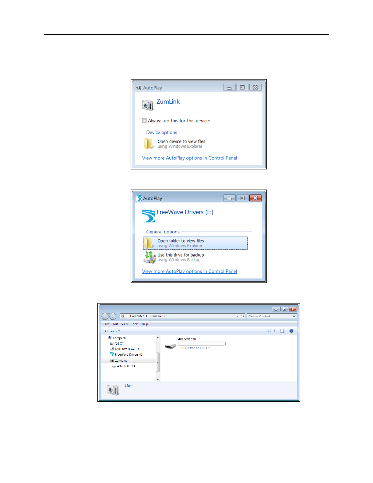
4. Connect the USB cable to the computer and the micro-USB end to the ZumLink.
The AutoPlay ZumLink, AutoPlay FreeWave Drivers, and ZumLink windows open.
Important!: The USB does NOT power the ZumLink. It only provides a configuration
interface.
Figure 3: AutoPlay ZumLink window
LUM0076AA Rev Jul-2017 Page 11 of 171
This document is the property of FreeWave Technologies, Inc. and contains proprietary information owned by
FreeWave. This document cannot be reproduced in whole or in part by any means without written permission from
FreeWave Technologies, Inc.
Page 12
3. Installation
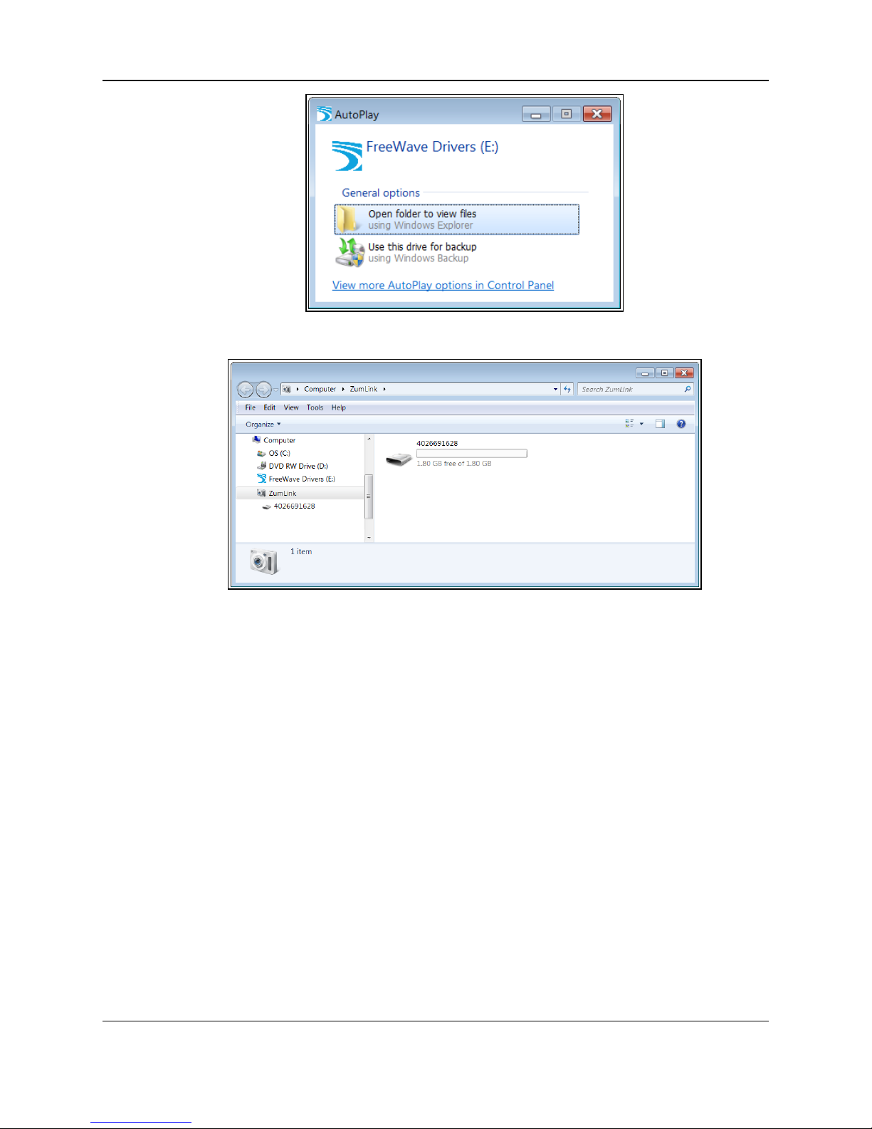
Figure 4: AutoPlay FreeWave Drivers window
Figure 5: ZumLink window
5. Use the Ethernet port for data communications.
6. Upgrade the ZumLink to the latest firmware using either of these procedures:
l Firmware Upgrade - Drag and Drop (on page 35)
l Firmware Upgrade - Web Interface (on page 43)
Page 12 of 171 LUM0076AA Rev Jul-2017
This document is the property of FreeWave Technologies, Inc. and contains proprietary information owned by
FreeWave. This document cannot be reproduced in whole or in part by any means without written permission from
FreeWave Technologies, Inc.
Page 13
ZumLink™ Z9-P / Z9-PE: User Manual
4. Drag and Drop Configuration
Caution: This procedure requires the Windows® Explorer file extension to be visible.
See the Microsoft® topic Show or Hide File Name Extensions to view the extensions.
Important!: Windows® 7 or later is required to use the USB Drag and Drop.
Note: The images in this procedure are for Windows® 7 and/or Firefox®.
The dialog boxes and windows appear differently on each computer.
Procedure
1. Connect the USB cable to the computer and the micro-USB end to the ZumLink.
The AutoPlay ZumLink, AutoPlay FreeWave Drivers, and ZumLink windows open.
LUM0076AA Rev Jul-2017 Page 13 of 171
This document is the property of FreeWave Technologies, Inc. and contains proprietary information owned by
FreeWave. This document cannot be reproduced in whole or in part by any means without written permission from
Figure 6: AutoPlay ZumLink window
FreeWave Technologies, Inc.
Page 14
4. Drag and Drop Configuration
Figure 7: AutoPlay FreeWave Drivers window
Figure 8: ZumLink window
2. Close the AutoPlay windows.
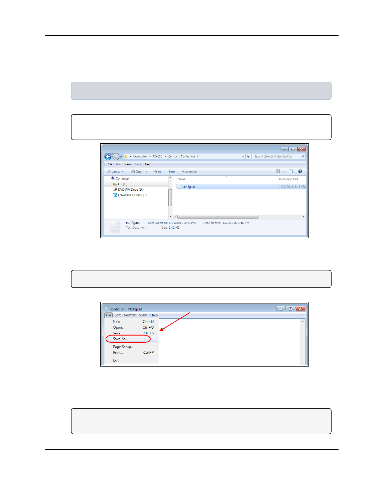
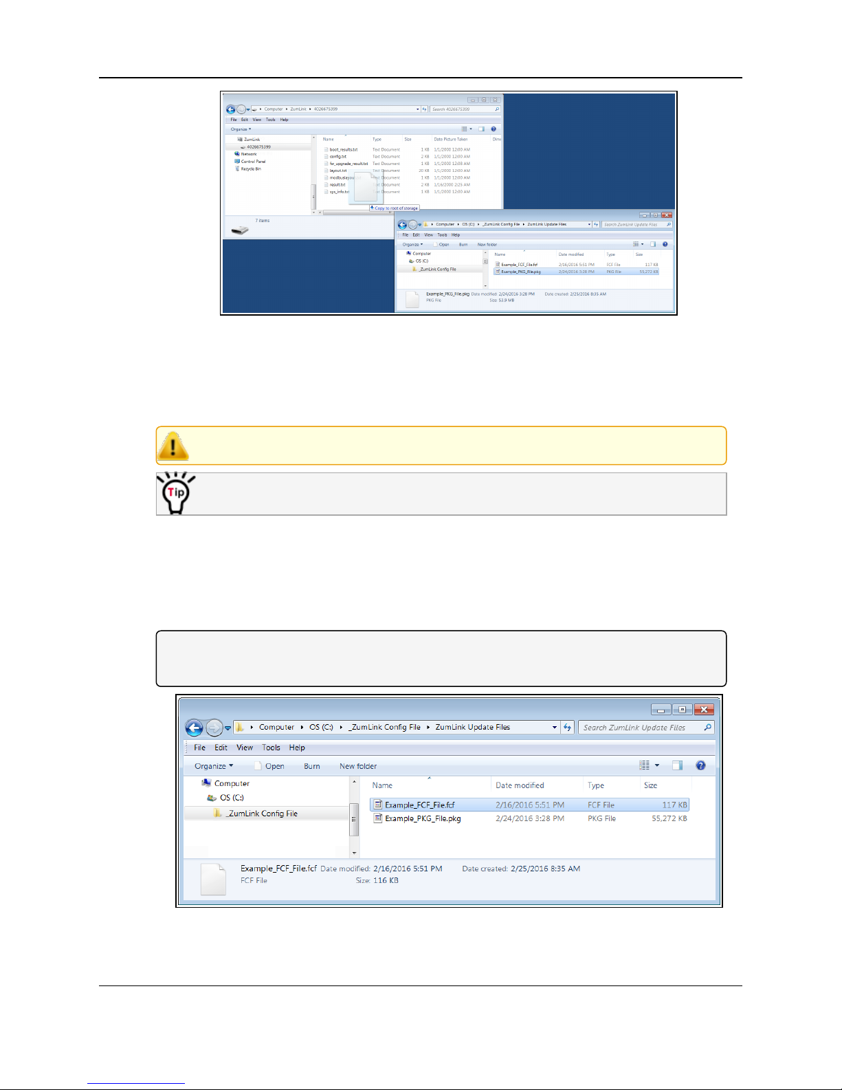
3. In the ZumLink window, double-click the connected ZumLink.
The files of the ZumLink appear in the window.
Figure 9: Opened ZumLink window showing the ZumLink files
Page 14 of 171 LUM0076AA Rev Jul-2017
This document is the property of FreeWave Technologies, Inc. and contains proprietary information owned by
FreeWave. This document cannot be reproduced in whole or in part by any means without written permission from
FreeWave Technologies, Inc.
Page 15
ZumLink™ Z9-P / Z9-PE: User Manual
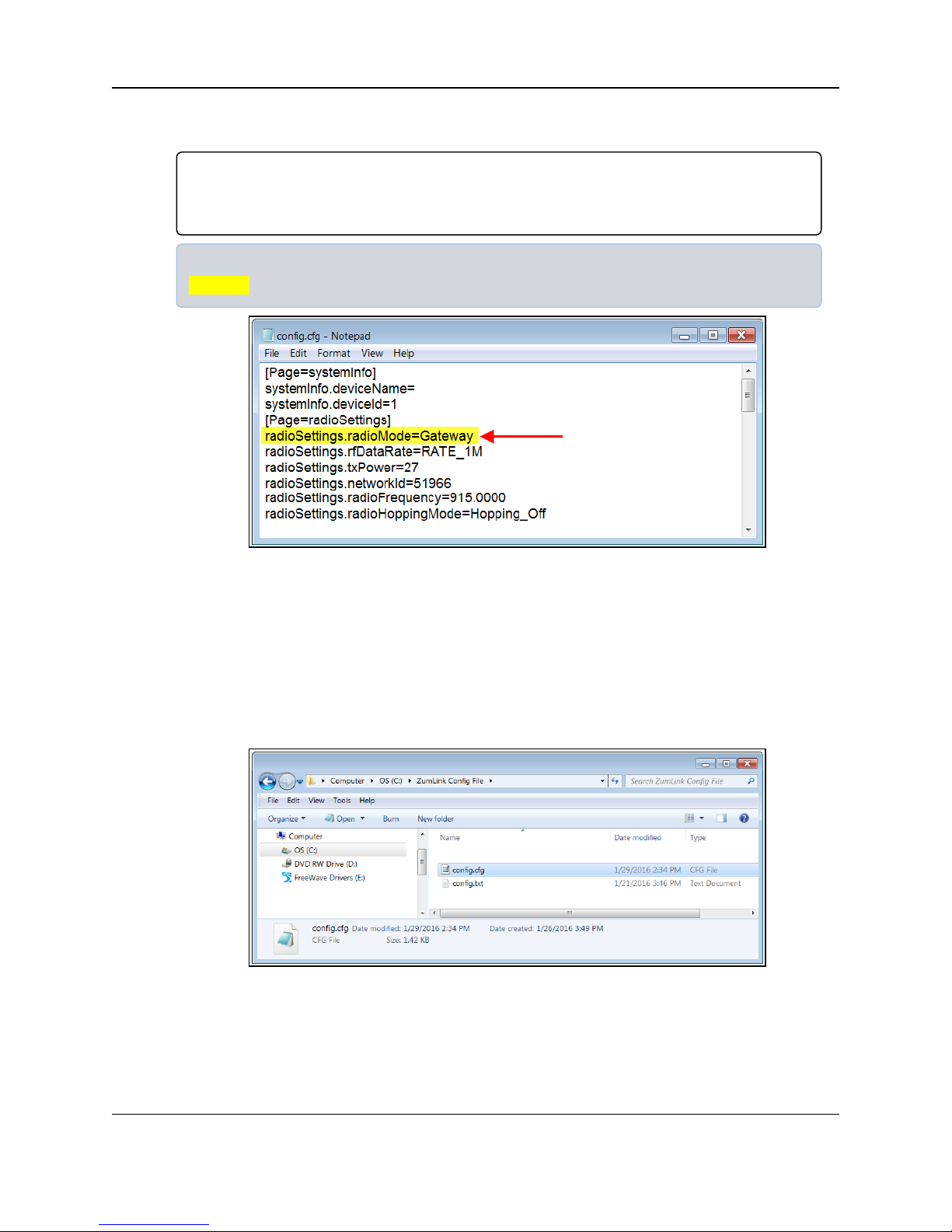
4. Select the config.txt file and copy it to the clipboard (press <Ctrl+C>).
5. Leave the ZumLink window open - it is used later in the procedures.
6. Open a Windows® Explorer window and create a designated folder for changed
configuration files.
Example: C:\ZumLink Config File.
7. Paste (press <Ctrl+V>) the copied config.txt file into the designated folder.
Important!: The txt file must be copied to a separate location on the computer to edit.
The file CANNOT be changed directly in the ZumLink folder.
Figure 10: Copied config.txt file in the designated configuration folder.
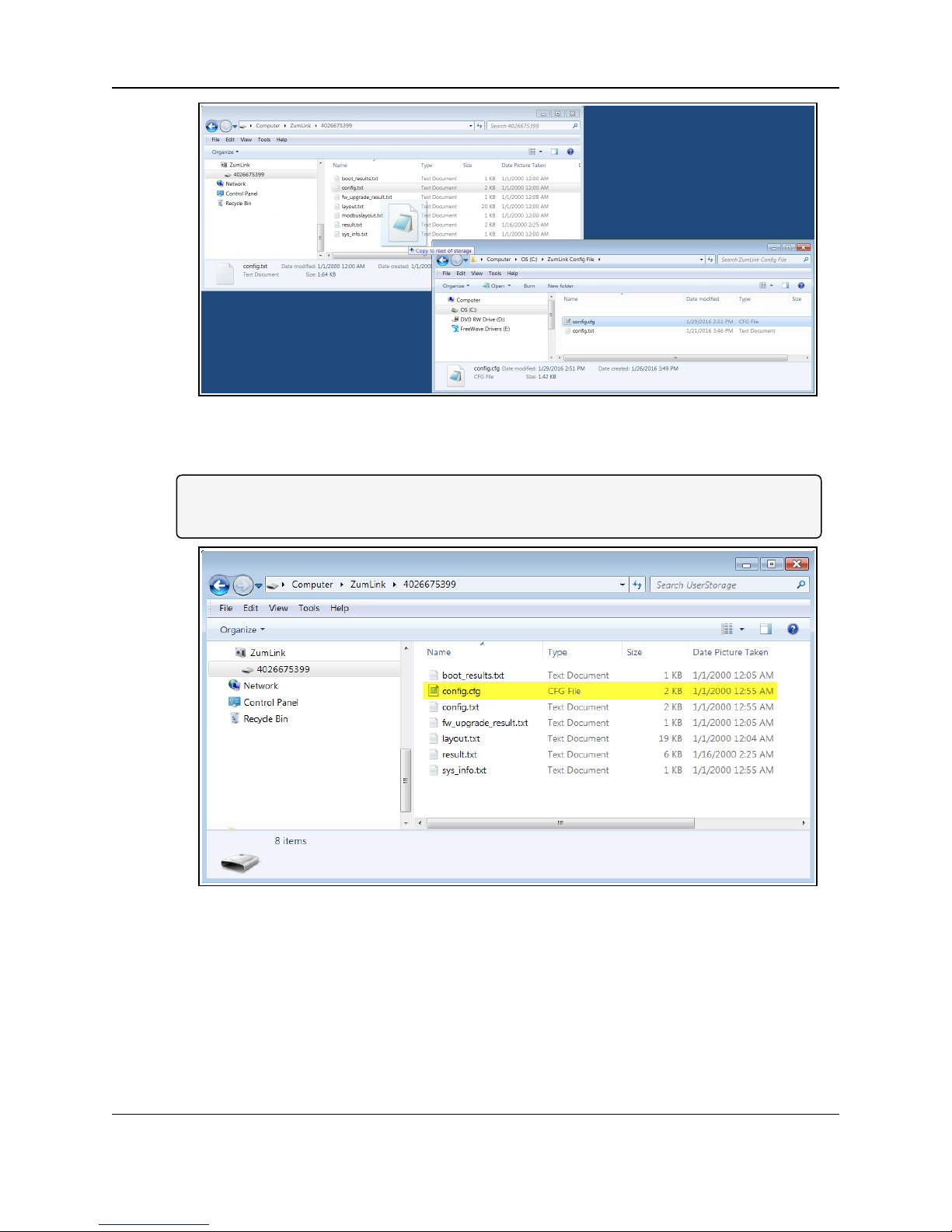
8. Double-click the config.txt to open it in the default text editor.
Note: This example uses Notepad®.
9. Click the Notepad®File menu and click Save As.
Figure 11: Notepad® window - File > Save As menu.
The Save As dialog box opens.
10. In the File Name text box, enter a file name with either the .cfg or .cfg.txt extension.
Note: The file name used in this example is for illustration purposes only.
Any name can be used. NO SPACES are allowed in the file name.
LUM0076AA Rev Jul-2017 Page 15 of 171
This document is the property of FreeWave Technologies, Inc. and contains proprietary information owned by
FreeWave. This document cannot be reproduced in whole or in part by any means without written permission from
FreeWave Technologies, Inc.
Page 16

4. Drag and Drop Configuration
Caution: A .cfg file extension is required for Windows® 7.
A .cfg.txt file extension is required for Windows® 8 and Windows® 10.
Failure to save the file with the correct extension type results in the file NOT being able
to integrate with the ZumLink config.txt file when copied to the ZumLink window.
11. Click the Save as type list box arrow and select All Files.
Figure 12: Save As dialog box with All Files (*.*) selected.
12.
Click .
The dialog box closes and the text editor returns with the new .cfg or .cfg.txt file open.
13. As applicable, change these general settings:
l [Page=systemInfo]
l systemInfo.deviceName
l systemInfo.deviceId
Note: See systemInfo (on page 138) for detailed information about these settings.
l [Page=radioSettings]
l radioSettings.txPower
l radioSettings.rfDataRate***
l radioSettings.radioMode
l radioSettings.networkId***
l radioSettings.nodeId**
l radioSettings.radioFrequency***
l radioSettings.radioHoppingMode***
l radioSettings.beaconInterval
Note: See radioSettings (on page 111) for detailed information about these settings.
**Each radio with the same networkId must have a UNIQUE nodeId.
Page 16 of 171 LUM0076AA Rev Jul-2017
This document is the property of FreeWave Technologies, Inc. and contains proprietary information owned by
FreeWave. This document cannot be reproduced in whole or in part by any means without written permission from
FreeWave Technologies, Inc.
Page 17
ZumLink™ Z9-P / Z9-PE: User Manual
***These are the Golden Settings and they MUST match between the ZumLink Gateway
and Endpoints.
Important!: With radioHoppingMode enabled, only one radio can be designated as a
Gateway. All other radios MUST be designated as Endpoints. For detailed information, see
radioSettings (on page 111) in the ZumLink Z9-P / Z9-PE Settings and Descriptions section.
Example: For illustration, the radioSettings.radioMode was changed from Endpoint to
Gateway.
Figure 13: Notepad® with the .cfg file open.
14. Press <Ctrl+S> or, on the File menu, click Save to save the updated file.
15. Close the text editor.
16. Locate and open the ZumLink window so it is side-by-side with the changed configuration
file window.
17. Open the Windows® Explorer designated folder for changed configuration files.
18. Select the changed .cfg or .cfg.txt file.
Figure 14: Select the changed .cfg or .cfg.txt file.
19. Drag and drop the .cfg or .cfg.txt file to the ZumLink window.
LUM0076AA Rev Jul-2017 Page 17 of 171
This document is the property of FreeWave Technologies, Inc. and contains proprietary information owned by
FreeWave. This document cannot be reproduced in whole or in part by any means without written permission from
FreeWave Technologies, Inc.
Page 18
4. Drag and Drop Configuration
Figure 15: Drag and drop the .cfg or .cfg.txt file to the ZumLink window.
20. Wait for the .cfg or .cfg.txt file to integrate with the ZumLink config.txt file.
Note: The more changes made in the .cfg or .cfg.txt file, the longer the ZumLink takes to
process the file and update the config.txt file.
Figure 16: Changed .cfg file copied to the ZumLink window.
When the config.txt is updated, the changed .cfg or .cfg.txt file is removed from the list of
files in the ZumLink window.
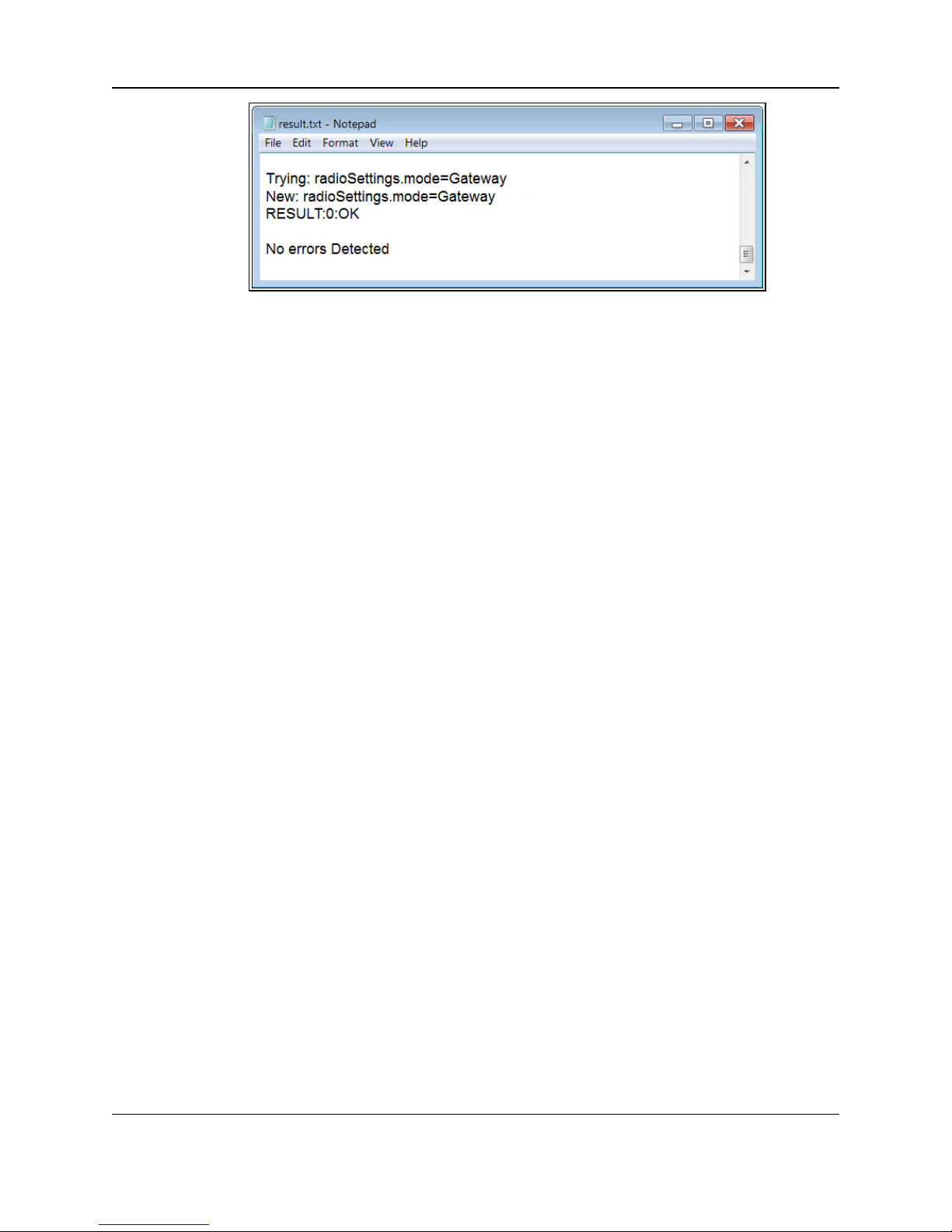
21. Double-click the result.txt file to verify there are No errors Detected with the identified
changes in the file.
Page 18 of 171 LUM0076AA Rev Jul-2017
This document is the property of FreeWave Technologies, Inc. and contains proprietary information owned by
FreeWave. This document cannot be reproduced in whole or in part by any means without written permission from
FreeWave Technologies, Inc.
Page 19
ZumLink™ Z9-P / Z9-PE: User Manual
Figure 17: Opened result.txt file.
If an error was detected, the result.txt file will indicate that errors are present.
22. As appropriate, repeat the Drag and Drop procedure to correct any errors.
23. Optional: Double-click the config.txt file to view the new ZumLink configuration.
LUM0076AA Rev Jul-2017 Page 19 of 171
This document is the property of FreeWave Technologies, Inc. and contains proprietary information owned by
FreeWave. This document cannot be reproduced in whole or in part by any means without written permission from
FreeWave Technologies, Inc.
Page 20

ZumLink™ Z9-P / Z9-PE: User Manual
5. CLI Configuration
This procedure provides a Tera Term terminal connection to the ZumLink CLI.
The basic steps are:
A. Connect the ZumLink Z9-P / Z9-PE to the Computer (on page 21)
B. Optional: Installing the ZumLink Z9-P / Z9-PE Driver (on page 23)
C. Tera Term Activation & ZumLink Z9-P / Z9-PE Setup (on page 28)
Note: The images in this procedure are for Windows® 7 and/or Firefox®.
The dialog boxes and windows appear differently on each computer.
LUM0076AA Rev Jul-2017 Page 20 of 171
This document is the property of FreeWave Technologies, Inc. and contains proprietary information owned by
FreeWave. This document cannot be reproduced in whole or in part by any means without written permission from
FreeWave Technologies, Inc.
Page 21

5. CLI Configuration
5.1. Connect the ZumLink Z9-P / Z9-PE to the Computer
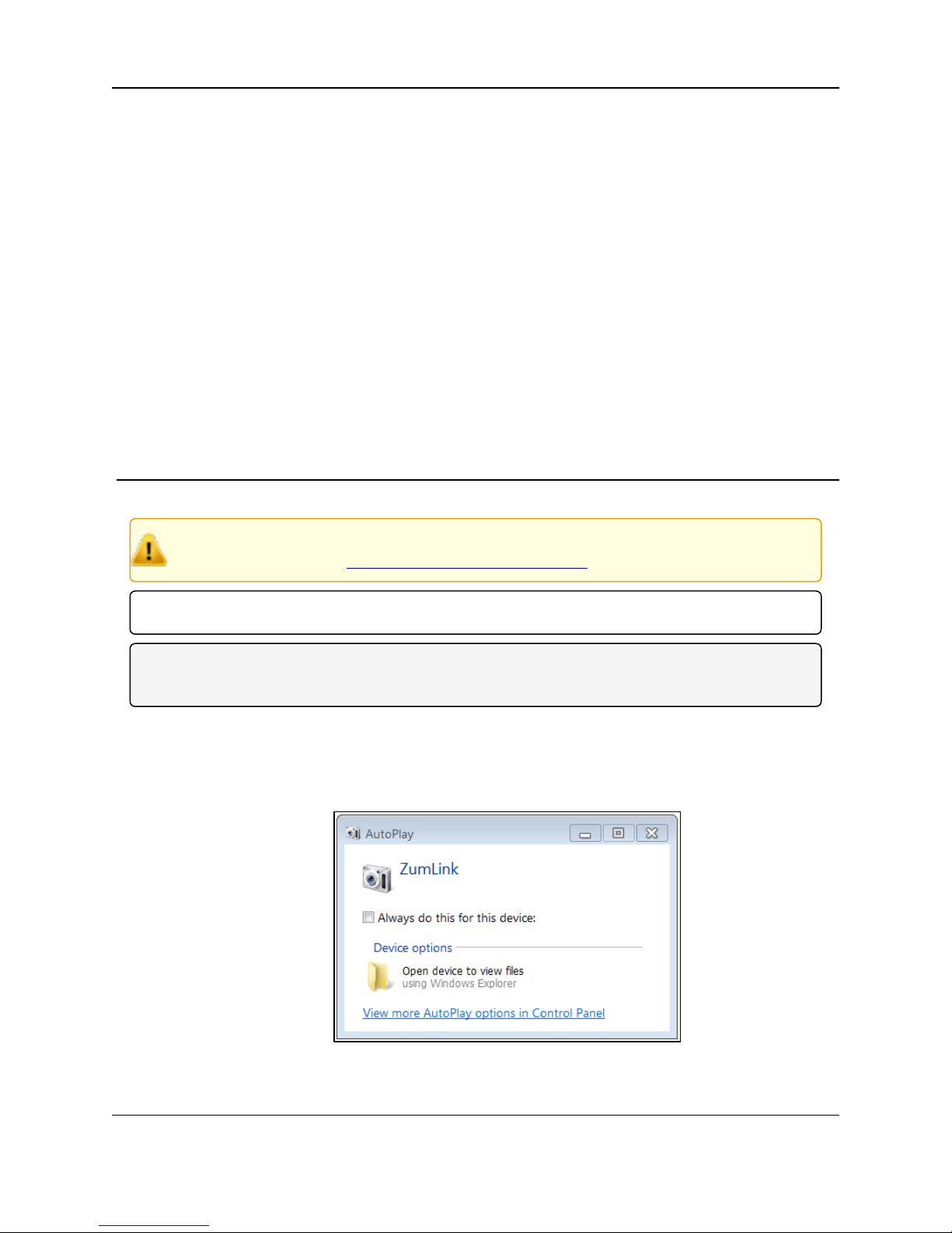
1. Connect the USB cable to the computer and the micro-USB end to the ZumLink.
The AutoPlay ZumLink, AutoPlay FreeWave Drivers, and ZumLink windows open.
Figure 18: AutoPlay ZumLink window
Figure 19: AutoPlay FreeWave Drivers window
Page 21 of 171 LUM0076AA Rev Jul-2017
This document is the property of FreeWave Technologies, Inc. and contains proprietary information owned by
FreeWave. This document cannot be reproduced in whole or in part by any means without written permission from
Figure 20: ZumLink window
FreeWave Technologies, Inc.
Page 22
ZumLink™ Z9-P / Z9-PE: User Manual
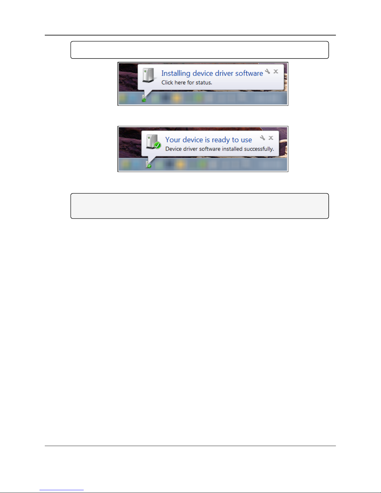
Important!: The ZumLink driver installs automatically.
Figure 21: Installing Driver message
Figure 22: Driver ready to use message
Note: If the ZumLink driver does NOT automatically install, complete the Installing the
ZumLink Z9-P / Z9-PE Driver (on page 23) procedure.
2. Continue with Tera Term Activation & ZumLink Z9-P / Z9-PE Setup (on page 28).
LUM0076AA Rev Jul-2017 Page 22 of 171
This document is the property of FreeWave Technologies, Inc. and contains proprietary information owned by
FreeWave. This document cannot be reproduced in whole or in part by any means without written permission from
FreeWave Technologies, Inc.
Page 23
5. CLI Configuration
5.2. Installing the ZumLink Z9-P / Z9-PE Driver
Note: Follow this procedure if the ZumLink driver does NOTautomatically install.
The images in this procedure are for Windows® 7 and/or Firefox®.
The dialog boxes and windows appear differently on each computer.
1. In the AutoPlay FreeWave Drivers window, make a note of the drive letter (in this
example image, it is E).
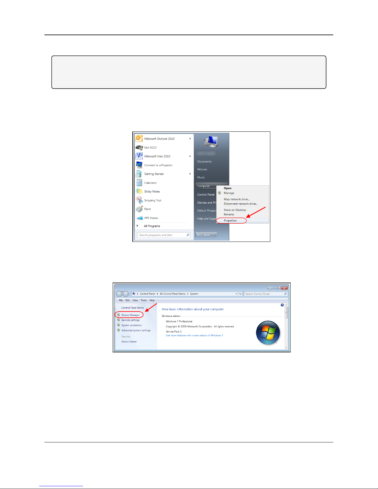
2. Click the Windows® Start button and right-click on Computer.
3. In the right-click menu, click Properties.
Figure 23: Right-click Properties on the menu.
The System window opens.
4. Click Device Manager.
Figure 24: Click Device Manager.
The Device Manager window opens.
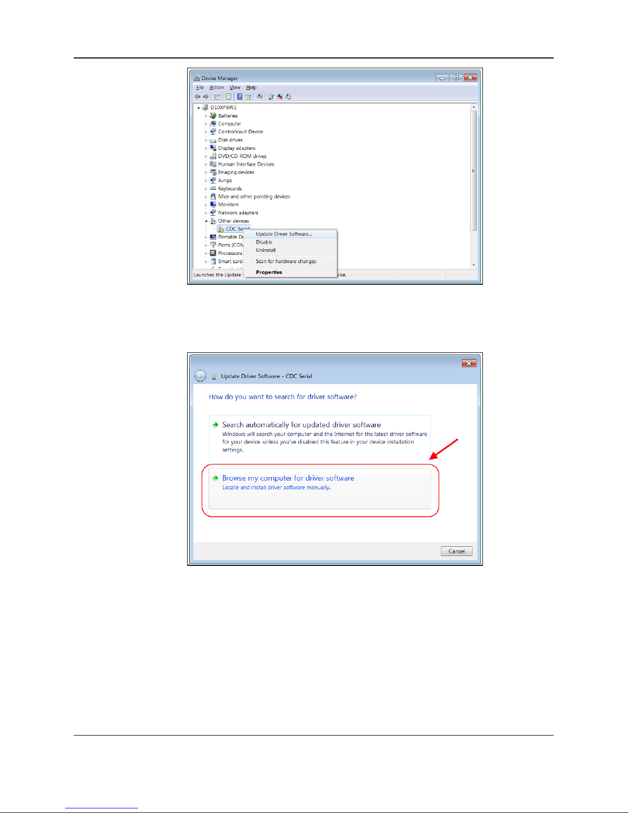
5. Under Other Devices, right-click the CDC Serial device and select Update Driver
Software.
Page 23 of 171 LUM0076AA Rev Jul-2017
This document is the property of FreeWave Technologies, Inc. and contains proprietary information owned by
FreeWave. This document cannot be reproduced in whole or in part by any means without written permission from
FreeWave Technologies, Inc.
Page 24
ZumLink™ Z9-P / Z9-PE: User Manual
Figure 25: Right-click CDC Serial and click Update Driver Software.
The Update Driver Software - CDC Serial dialog box opens.
6. Click Browse my computer for driver software.
Figure 26: Update Driver Software - CDC Serial dialog box
The Update Driver Software - CDC Serial dialog box refreshes with the active Browse
option.
LUM0076AA Rev Jul-2017 Page 24 of 171
This document is the property of FreeWave Technologies, Inc. and contains proprietary information owned by
FreeWave. This document cannot be reproduced in whole or in part by any means without written permission from
FreeWave Technologies, Inc.
Page 25

5. CLI Configuration
Figure 27: Update Driver Software - CDC Serial dialog box with Browse
option
7.
Click .
The Browse For Folder dialog box opens.
8. Select the drive letter identified in the Removable Disk AutoPlay FreeWave Drivers
window.
Note: The driver letter shown in the image is an example only.
Figure 28: Browse For Folder dialog box
9. Click OK to save the selection and close the dialog box.
The Update Driver Software - CDC Serial dialog box returns with the selected drive.
Page 25 of 171 LUM0076AA Rev Jul-2017
This document is the property of FreeWave Technologies, Inc. and contains proprietary information owned by
FreeWave. This document cannot be reproduced in whole or in part by any means without written permission from
FreeWave Technologies, Inc.
Page 26

Figure 29: Update Driver Software - CDC Serial dialog box with selected
10. Click Next.
The Windows Security dialog box opens.
ZumLink™ Z9-P / Z9-PE: User Manual
drive
11. Click Install.
The driver software is installed.
The dialog box refreshes showing a successful driver install.
LUM0076AA Rev Jul-2017 Page 26 of 171
This document is the property of FreeWave Technologies, Inc. and contains proprietary information owned by
FreeWave. This document cannot be reproduced in whole or in part by any means without written permission from
Figure 30: Windows Security dialog box
Figure 31: Installing driver software
FreeWave Technologies, Inc.
Page 27
5. CLI Configuration
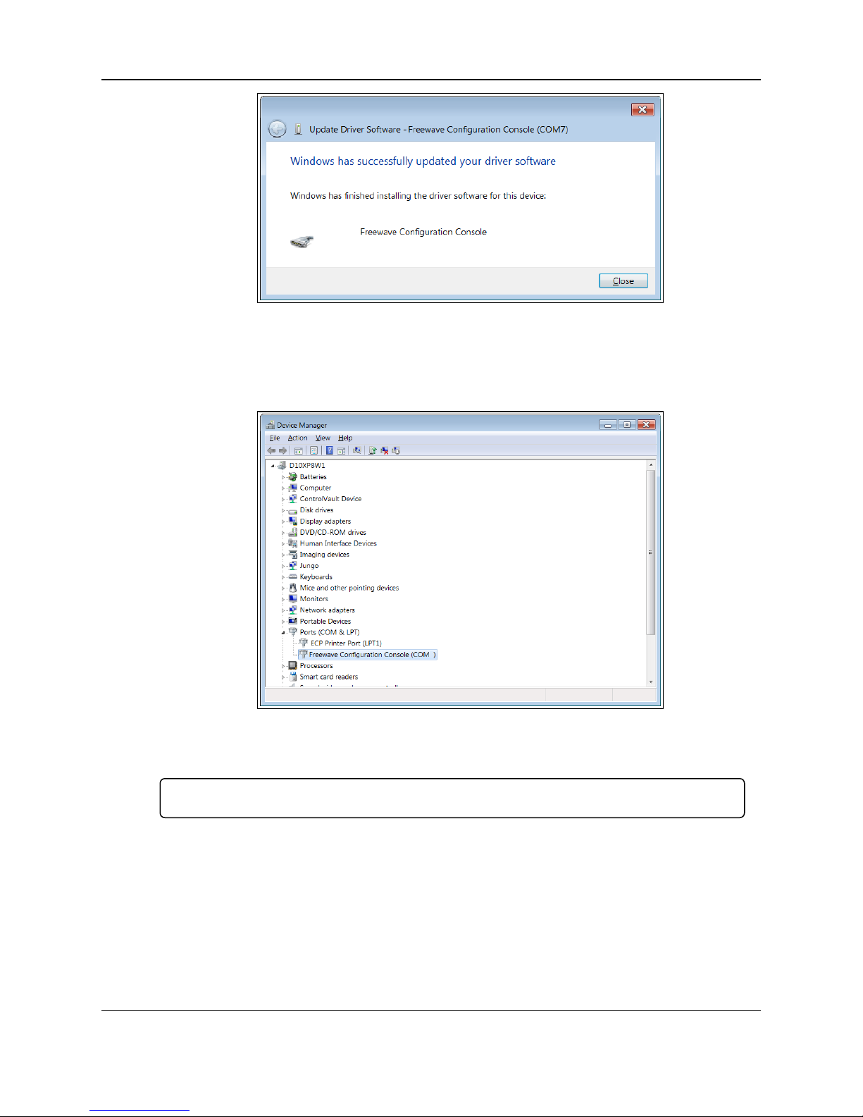
12. Click Close.
The Device Manager window returns showing the FreeWave Configuration Console
added to the Ports.
Figure 32: Successful driver installation.
Figure 33: The Device Manager window showing the FreeWave
Configuration Console device and its assigned COM Port number.
Important!: The Port assignment varies from computer to computer.
Page 27 of 171 LUM0076AA Rev Jul-2017
This document is the property of FreeWave Technologies, Inc. and contains proprietary information owned by
FreeWave. This document cannot be reproduced in whole or in part by any means without written permission from
FreeWave Technologies, Inc.
Page 28
ZumLink™ Z9-P / Z9-PE: User Manual
5.3. Tera Term Activation & ZumLink Z9-P / Z9-PE Setup
Note: The images in this procedure are for Windows® 7 and/or Firefox®.
The dialog boxes and windows appear differently on each computer.
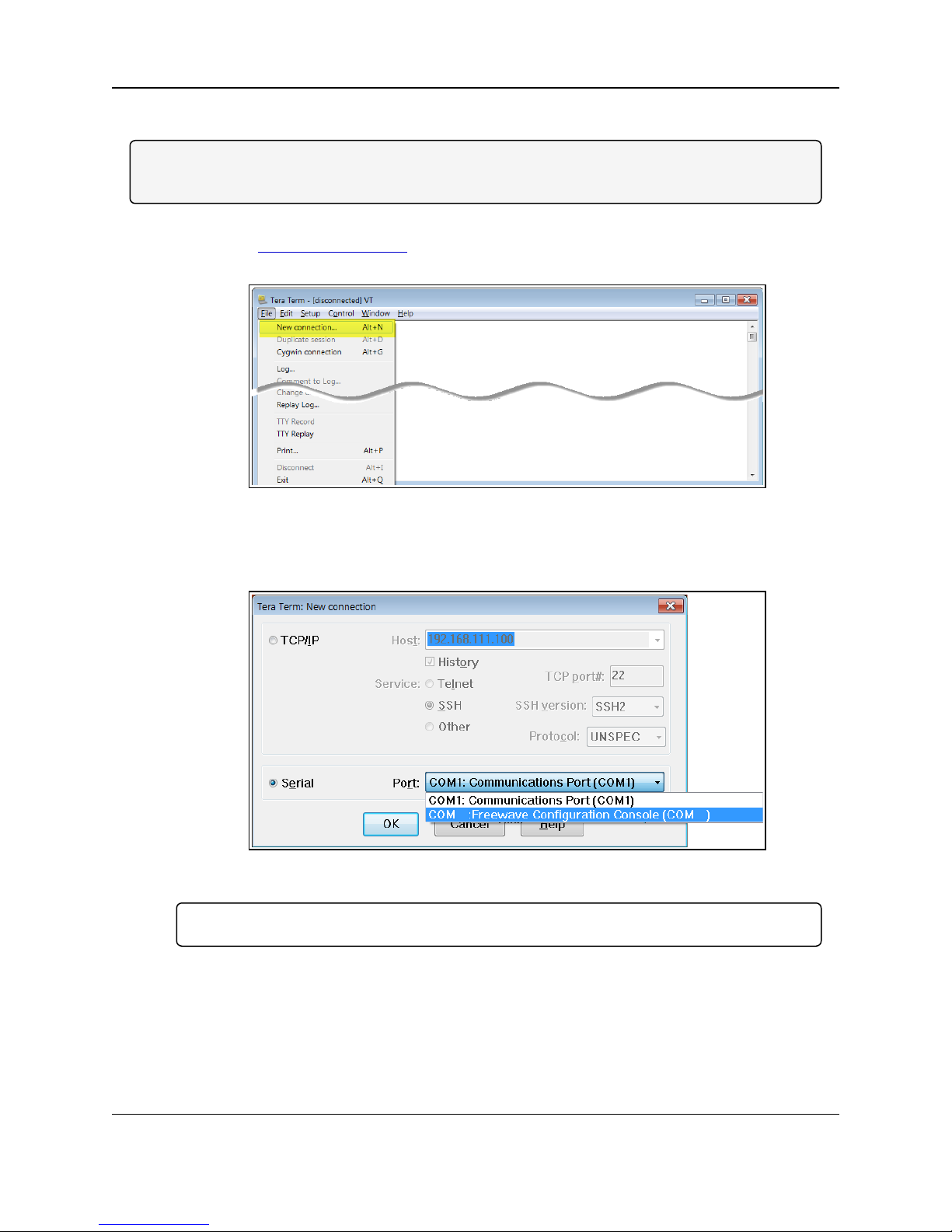
1. On the computer connected to the ZumLink Z9-P / Z9-PE, open a terminal program (e.g.,
Tera Term http://ttssh2.osdn.jp/).
2. In Tera Term, on the File menu, select New Connection.
Figure 34: File menu > New Connection
The Tera Term New Connection dialog box opens.
3. Click the Port list box arrow and select the COM port the ZumLink device is connected to.
Figure 35: Select the ZumLink Z9-P / Z9-PE COM port
Important!: The Port assignment varies from computer to computer.
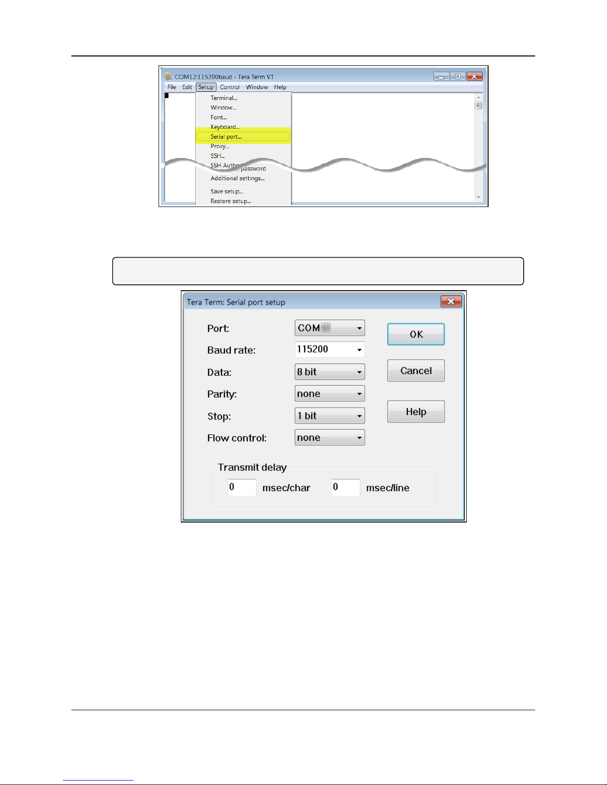
4. Click OK to save the changes and close the dialog box.
The Tera Term window shows the connected COM port and Baud rate in the title bar of the
window.
5. In the Tera Term window, click the Setup menu and select Serial Port.
LUM0076AA Rev Jul-2017 Page 28 of 171
This document is the property of FreeWave Technologies, Inc. and contains proprietary information owned by
FreeWave. This document cannot be reproduced in whole or in part by any means without written permission from
FreeWave Technologies, Inc.
Page 29
5. CLI Configuration
The Tera Term: Serial Port Setup dialog box opens.
Note: The image shows the default ZumLink settings.
Figure 36: Serial menu > Setup Port
Figure 37: Tera Term: Serial Port Setup dialog box with default settings
6. Verify the COM port settings are:
Baud Rate: 115200
Data: 8 bit
Parity: none
Stop: 1 bit
7. Click OK to save the changes and close the dialog box.
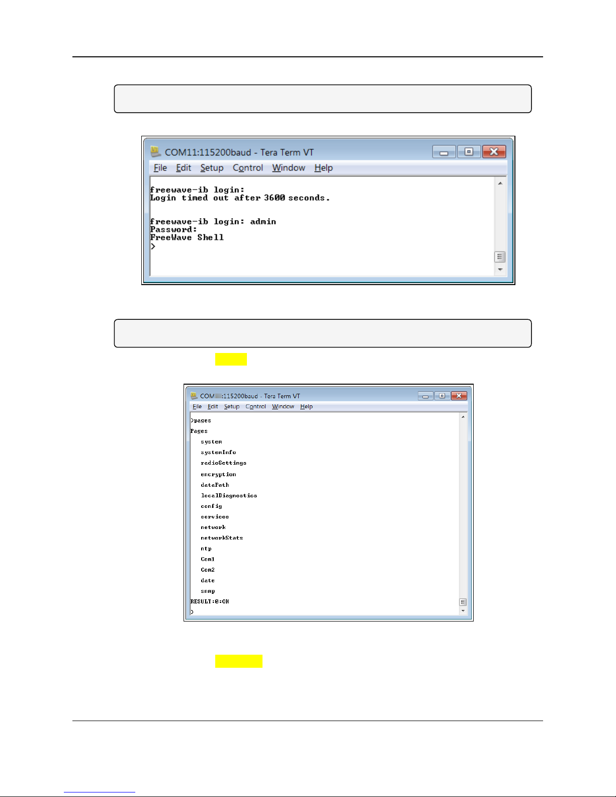
8. In the Tera Term window, press <Enter>.
The ZumLink CLI Login returns.
9. Type admin to login and press <Enter>.
Page 29 of 171 LUM0076AA Rev Jul-2017
This document is the property of FreeWave Technologies, Inc. and contains proprietary information owned by
FreeWave. This document cannot be reproduced in whole or in part by any means without written permission from
FreeWave Technologies, Inc.
Page 30
ZumLink™ Z9-P / Z9-PE: User Manual
10. When prompted, type admin for the password and press <Enter>.
Note: The password does not appear when typing - it looks blank.
The FreeWave Shell returns.
Figure 38: The FreeWave Shell returns.
Note: The login times out after 3600 seconds. Repeat the login procedure if needed.
11. At the > prompt, type pages and press <Enter>.
The available ZumLink information appears.
Figure 39: ZumLink Z9-P / Z9-PE Pages information
12. At the > prompt, type network and press <Enter>.
The ZumLink network settings appear.
LUM0076AA Rev Jul-2017 Page 30 of 171
This document is the property of FreeWave Technologies, Inc. and contains proprietary information owned by
FreeWave. This document cannot be reproduced in whole or in part by any means without written permission from
FreeWave Technologies, Inc.
Page 31

5. CLI Configuration
Figure 40: ZumLink Z9-P / Z9-PE network Settings
Note: Steps 13 to 16 make the IP Address and nodeId unique to each radio.
Other values may be defined as long as they are unique to each radio.
13. At the > prompt, type ip_address=192.168.1.nnn and press <Enter>.
Note: Where nnn = the same unique 3 digit number.
14. At the > prompt, type radiosettings and press <Enter>.
The ZumLink radioSettings appear.
Note: Figure 41 shows ALL available settings for the page.
Only radioSettings that apply to the current radioMode, HoppingMode, and rfDataRate are
visible and can be changed.
Page 31 of 171 LUM0076AA Rev Jul-2017
This document is the property of FreeWave Technologies, Inc. and contains proprietary information owned by
FreeWave. This document cannot be reproduced in whole or in part by any means without written permission from
FreeWave Technologies, Inc.
Page 32

ZumLink™ Z9-P / Z9-PE: User Manual
Figure 41: ZumLink Z9-P / Z9-PE radioSettings
15. At the > prompt, type nodeId=nnn and press <Enter>.
Note: Where nnn = the same unique 3 digit number.
16. At the > prompt, type save and press <Enter>.
LUM0076AA Rev Jul-2017 Page 32 of 171
This document is the property of FreeWave Technologies, Inc. and contains proprietary information owned by
FreeWave. This document cannot be reproduced in whole or in part by any means without written permission from
FreeWave Technologies, Inc.
Page 33

ZumLink™ Z9-P / Z9-PE: User Manual
6. Creating a Basic ZumLink
Gateway and Endpoint Network
Note: The setting changes described in this procedure can be changed using either the Drag and
Drop Configuration (on page 13) or by accessing the CLI Configuration (on page 20).
Figure 42 shows a basic network setup for the ZumLink Z9-PE.
Figure 42: A Basic ZumLink Network
Procedure
Note: This example procedure is specific for CLI configuration.
1. Connect power to the ZumLink devices in the network.
2. Optional: Upgrade the devices using one of these procedures:
Firmware Upgrade - Drag and Drop (on page 35).
Firmware Upgrade - Web Interface (on page 43).
3. Complete the CLI Configuration (on page 20) procedure.
4. At the > prompt, type a setting between 10 and 30 for the radioSettings.txPower.
LUM0076AA Rev Jul-2017 Page 33 of 171
This document is the property of FreeWave Technologies, Inc. and contains proprietary information owned by
FreeWave. This document cannot be reproduced in whole or in part by any means without written permission from
FreeWave Technologies, Inc.
Page 34

6. Creating a Basic ZumLink Gateway and Endpoint Network
Example: txPower=30 or radioSettings.txPower=30.
Entering txpower=0 or radiosettings.txpower=0 changes the power to minimum or 10.
5. Select one radio and, at the > prompt, type radioSettings.radioMode=Gateway.
6. For the other radio in the network, at the > prompt, type
radioSettings.radioMode=Endpoint.
7. Verify the radioSettings.networkId= setting is the same on ALL radios in the
network.
Note: The nodId MUST be unique on each radio within the same networkId.
Optional: For Endpoints in the network, use the command:
radioSettings.nodeId=0.
This allows the Endpoint to automatically set the nodeId to a predetermined unique
number from 2 through 65533.
Important!: The Gateway radioSettings.nodeId defaults to 1 and CANNOT be changed.
8. At the > prompt, type network and press <Enter>.
The ZumLink network settings appear.
9. For each radio in the network, type network.ip_address=nnn, where nnn is a unique
IP Address for each radio.
10. At the > prompt, type save and press <Enter>.
A solid green CD LED indicates that the radios are linked.
11. Type logout and press <Enter> to exit the FreeWave Shell.
Page 34 of 171 LUM0076AA Rev Jul-2017
This document is the property of FreeWave Technologies, Inc. and contains proprietary information owned by
FreeWave. This document cannot be reproduced in whole or in part by any means without written permission from
FreeWave Technologies, Inc.
Page 35

ZumLink™ Z9-P / Z9-PE: User Manual
7. Firmware Upgrade - Drag and Drop
This procedure describes using drag and drop to upgrade the ZumLink Z9-P / Z9-PE firmware.
Alternatively, use the Firmware Upgrade - Web Interface (on page 43) to upgrade the ZumLink
Z9-P / Z9-PE.
Note: Go to http://support.freewave.com/ to login and download the latest firmware for the ZumLink
Z9-P / Z9-PE..
Registration is required to use this login.
The ZumLink Z9-P / Z9-PE upgrade process requires these basic steps:
A. Download the Upgrade File (on page 36)
B. Install the Upgrade File (on page 39)
Caution: This procedure requires the Windows® Explorer file extension to be visible.
See the Microsoft® topic Show or Hide File Name Extensions to view the extensions.
LUM0076AA Rev Jul-2017 Page 35 of 171
This document is the property of FreeWave Technologies, Inc. and contains proprietary information owned by
FreeWave. This document cannot be reproduced in whole or in part by any means without written permission from
FreeWave Technologies, Inc.
Page 36

7. Firmware Upgrade - Drag and Drop
7.1. Download the Upgrade File
Note: The images in this procedure are for Windows® 7 and/or Firefox®.
The dialog boxes and windows appear differently on each computer.
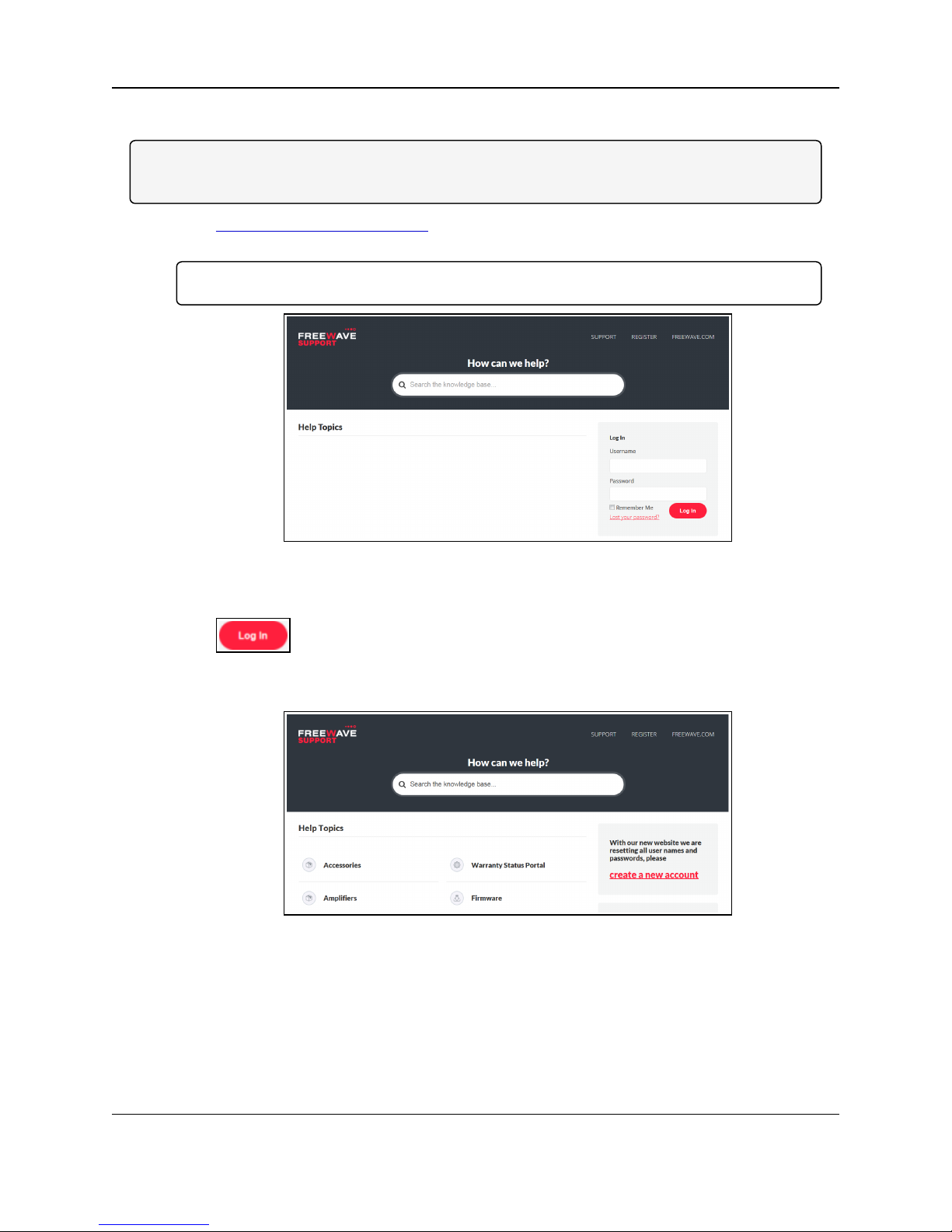
1. Click http://support.freewave.com/.
The Login window opens.
Important!: Registration is required to use this login.
Figure 43: FreeWave Login window
2. Enter the User Name and Password.
3.
Click .
A successful Login message briefly appears.
The Help Topics window opens.
Figure 44: Help Topics window
4. Click the Firmware link.
The Firmware window opens.
Page 36 of 171 LUM0076AA Rev Jul-2017
This document is the property of FreeWave Technologies, Inc. and contains proprietary information owned by
FreeWave. This document cannot be reproduced in whole or in part by any means without written permission from
FreeWave Technologies, Inc.
Page 37

Figure 45: Firmware window
5. Click the ZumLink Firmware link.
The available software appears in the window.
ZumLink™ Z9-P / Z9-PE: User Manual
Figure 46: ZumLink Firmware window
6. Click the software link.
The Firmware Upgrade window opens.
7. Select and click the attachment.
Figure 47: Firmware Upgrade window with selected attachment.
The Opening dialog box opens.
Note: This procedure shows Firefox® dialog boxes.
Other browsers will have different dialog boxes and procedures.
LUM0076AA Rev Jul-2017 Page 37 of 171
This document is the property of FreeWave Technologies, Inc. and contains proprietary information owned by
FreeWave. This document cannot be reproduced in whole or in part by any means without written permission from
FreeWave Technologies, Inc.
Page 38

7. Firmware Upgrade - Drag and Drop
Figure 48: Microsoft® Opening dialog box
8. Click OK.
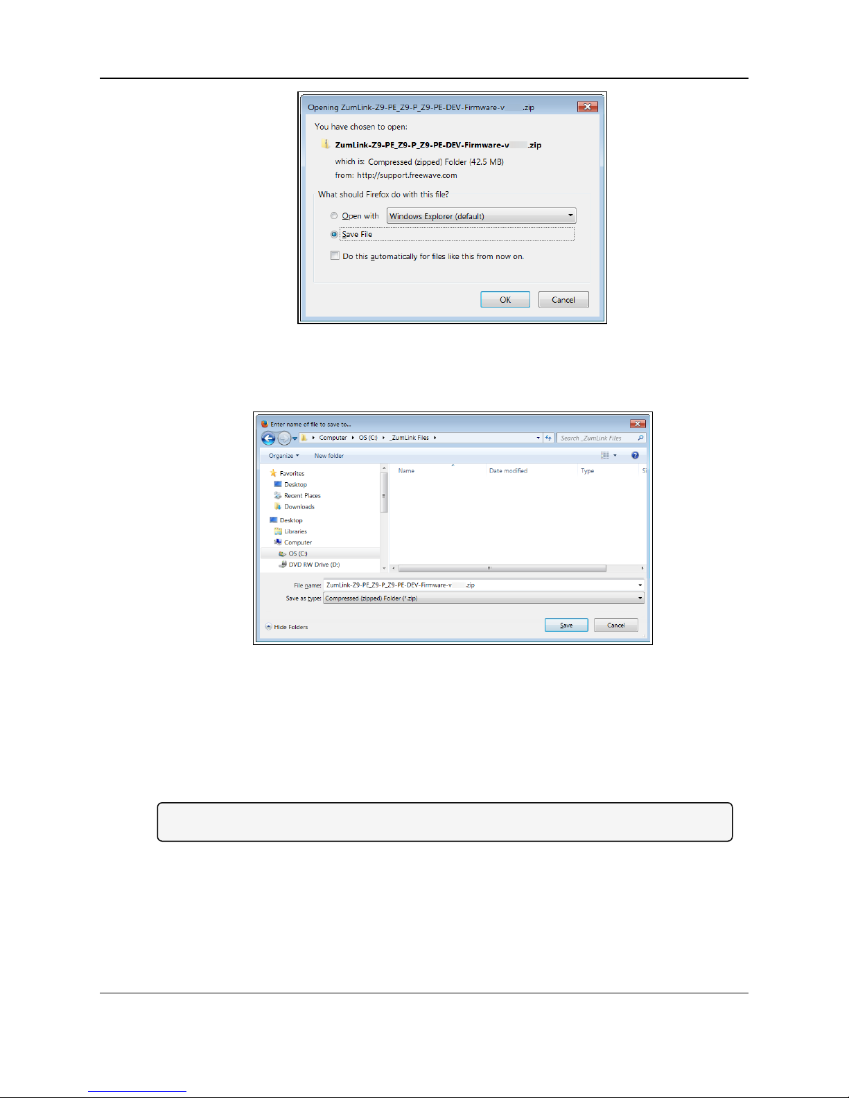
The Enter name of file to save to dialog box opens.
Figure 49: Microsoft® Enter name of file to save to dialog box
9. Search for and select a location to save the .zip file to and click Save.
The Enter name of file to save to dialog box closes.
10. Open a Windows® Explorer window and find the location where the .zip file was saved.
11. Double-click the .zip file.
12. Extract the files from the .zip file into the parent location.
Note: The files include the .pkg and .fcf files used in the upgrade process.
Page 38 of 171 LUM0076AA Rev Jul-2017
This document is the property of FreeWave Technologies, Inc. and contains proprietary information owned by
FreeWave. This document cannot be reproduced in whole or in part by any means without written permission from
FreeWave Technologies, Inc.
Page 39
ZumLink™ Z9-P / Z9-PE: User Manual
7.2. Install the Upgrade File
1. Connect the USB cable to the computer and the micro-USB end to the ZumLink.
The AutoPlay ZumLink, AutoPlay FreeWave Drivers, and ZumLink windows open.
Figure 50: AutoPlay ZumLink window
Figure 51: AutoPlay FreeWave Drivers window
LUM0076AA Rev Jul-2017 Page 39 of 171
This document is the property of FreeWave Technologies, Inc. and contains proprietary information owned by
FreeWave. This document cannot be reproduced in whole or in part by any means without written permission from
Figure 52: ZumLink window
FreeWave Technologies, Inc.
Page 40

7. Firmware Upgrade - Drag and Drop
2. In the ZumLink window, double-click the connected ZumLink.
The files of the ZumLink appear in the window.
Figure 53: Opened ZumLink window showing the ZumLink files
3. Optional: Select, copy, and paste the config.txt file to a secure location.
Note: This is to backup the current config.txt before the upgrade process in case the old
config.txt file needs to be restored.
4. Locate and select the downloaded ZumLink upgrade .pkg file.
Caution: A .pkg or .fcf file extension is required for Windows® 7.
A .pkg.txt or .fcf.txt file extension is required for Windows® 8, Windows® 8.1, and
Windows® 10.
Failure to save the file with the correct extension type results in the file NOT being able
to integrate with the ZumLink config.txt file when copied to the ZumLink window.
5. If using Windows® 8, Windows® 8.1, or Windows® 10, change the extension of the .pkg
file to .pkg.txt and select that file.
6. Drag and drop the .pkg or .pkg.txt file on to the ZumLink window.
Page 40 of 171 LUM0076AA Rev Jul-2017
This document is the property of FreeWave Technologies, Inc. and contains proprietary information owned by
FreeWave. This document cannot be reproduced in whole or in part by any means without written permission from
Figure 54: Selected .pkg file
FreeWave Technologies, Inc.
Page 41
ZumLink™ Z9-P / Z9-PE: User Manual
Figure 55: Drag and Drop the .pkg or .pkg.txt file to the ZumLink window
The .pkg or .pkg.txt file will disappear after approximately 6-10 minutes.
7. Wait a few minutes for the AutoPlay and ZumLink windows to close.
The ZumLink automatically reboots.
Caution: DO NOT remove power to the ZumLink Z9-P / Z9-PE during this process!
The LEDs (on page 158) provide an indication of the upgrade process.
The AutoPlay and ZumLink windows re-open when the .pkg or .pkg.txt upgrade file has
been applied.
8. In the ZumLink window, double-click the connected ZumLink.
The files of the ZumLink appear in the window.
9. Locate and select the downloaded ZumLink upgrade .fcf file.
Note: If required for Windows® 8, Windows® 8.1, or Windows® 10, change the extension of
the .fcf file to .fcf.txt and select that file.
10. Drag and drop the .fcf or .fcf.txt file on to the ZumLink window.
LUM0076AA Rev Jul-2017 Page 41 of 171
This document is the property of FreeWave Technologies, Inc. and contains proprietary information owned by
FreeWave. This document cannot be reproduced in whole or in part by any means without written permission from
Figure 56: Selected .fcf (or .fcf.txt) file
FreeWave Technologies, Inc.
Page 42
7. Firmware Upgrade - Drag and Drop
Figure 57: Drag and Drop the .fcf file to the ZumLink window
The .fcf or .fcf.txt file will disappear.
11. Wait for the .fcf or .fcf.txt file to be applied (≈ 1-2 minutes).
The LEDs (on page 158) provide an indication of the upgrade process.
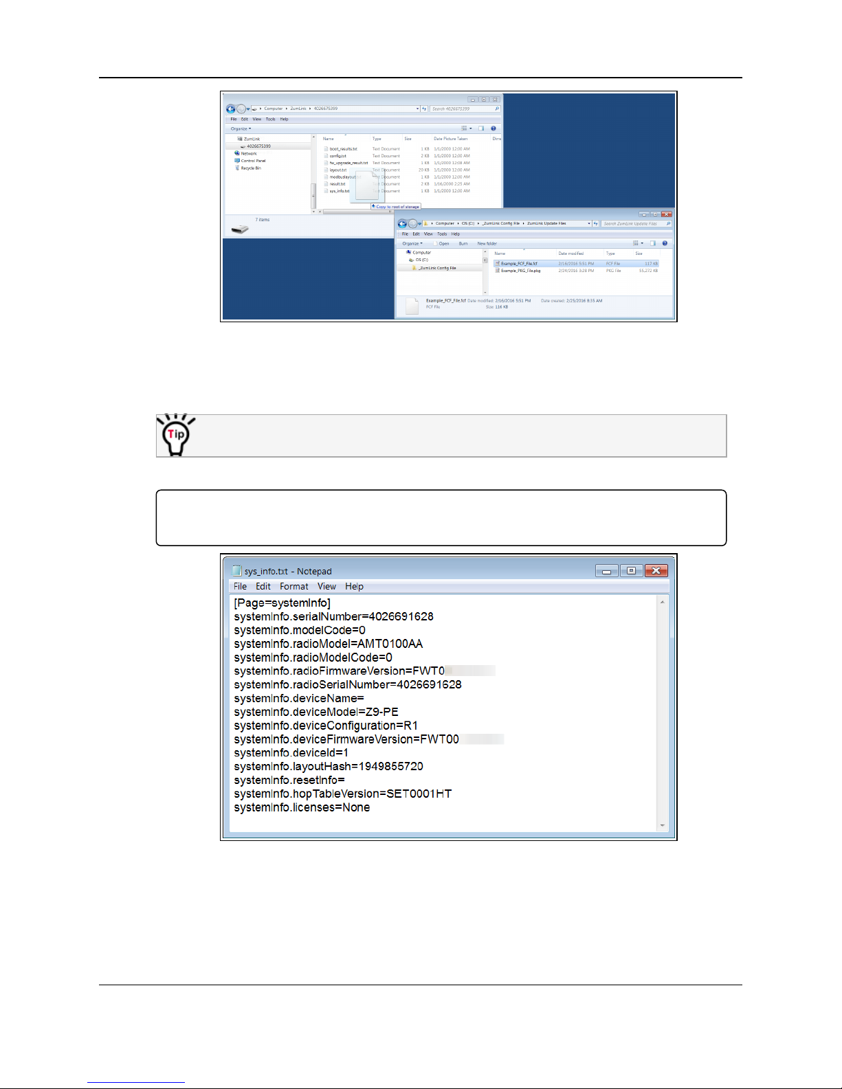
12. Optional: Open the sys.info.txt file to verify the upgrade information.
Important!: The image provides example information only. Each ZumLink provides its own
unique information.
Figure 58: ZumLink sys.info.txt file with updated firmware
13. Use the Drag and Drop Configuration (on page 13) procedure to configure the ZumLink.
Page 42 of 171 LUM0076AA Rev Jul-2017
This document is the property of FreeWave Technologies, Inc. and contains proprietary information owned by
FreeWave. This document cannot be reproduced in whole or in part by any means without written permission from
FreeWave Technologies, Inc.
Page 43

ZumLink™ Z9-P / Z9-PE: User Manual
8. Firmware Upgrade - Web Interface
This procedure describes using a web browser window to upgrade the ZumLink Z9-P / Z9-PE
firmware.
Alternatively, use the Firmware Upgrade - Drag and Drop (on page 35) to upgrade the ZumLink
Z9-P / Z9-PE.
The ZumLink Z9-P / Z9-PE upgrade process requires these basic steps:
l Download the Upgrade File (on page 44)
l Setup the Computer IP Address Configuration (on page 47)
l Install the Upgrade File using the Web Interface (on page 51)
Note: This method is used for computers running Windows® 7 and later.
LUM0076AA Rev Jul-2017 Page 43 of 171
This document is the property of FreeWave Technologies, Inc. and contains proprietary information owned by
FreeWave. This document cannot be reproduced in whole or in part by any means without written permission from
FreeWave Technologies, Inc.
Page 44
8. Firmware Upgrade - Web Interface
8.1. Download the Upgrade File
Note: The images in this procedure are for Windows® 7 and/or Firefox®.
The dialog boxes and windows appear differently on each computer.
1. Click http://support.freewave.com/.
The Login window opens.
Important!: Registration is required to use this login.
Figure 59: FreeWave Login window
2. Enter the User Name and Password.
3.
Click .
A successful Login message briefly appears.
The Help Topics window opens.
Figure 60: Help Topics window
4. Click the Firmware link.
The Firmware window opens.
Page 44 of 171 LUM0076AA Rev Jul-2017
This document is the property of FreeWave Technologies, Inc. and contains proprietary information owned by
FreeWave. This document cannot be reproduced in whole or in part by any means without written permission from
FreeWave Technologies, Inc.
Page 45

Figure 61: Firmware window
5. Click the ZumLink Firmware link.
The available software appears in the window.
ZumLink™ Z9-P / Z9-PE: User Manual
Figure 62: ZumLink Firmware window
6. Click the software link.
The Firmware Upgrade window opens.
7. Select and click the attachment.
Figure 63: Firmware Upgrade window with selected attachment.
The Opening dialog box opens.
Note: This procedure shows Firefox® dialog boxes.
Other browsers will have different dialog boxes and procedures.
LUM0076AA Rev Jul-2017 Page 45 of 171
This document is the property of FreeWave Technologies, Inc. and contains proprietary information owned by
FreeWave. This document cannot be reproduced in whole or in part by any means without written permission from
FreeWave Technologies, Inc.
Page 46
8. Firmware Upgrade - Web Interface
Figure 64: Microsoft® Opening dialog box
8. Click OK.
The Enter name of file to save to dialog box opens.
Figure 65: Microsoft® Enter name of file to save to dialog box
9. Search for and select a location to save the .zip file to and click Save.
The Enter name of file to save to dialog box closes.
10. Open a Windows® Explorer window and find the location where the .zip file was saved.
11. Double-click the .zip file.
12. Extract the files from the .zip file into the parent location.
Note: The files include the .pkg and .fcf files used in the upgrade process.
Page 46 of 171 LUM0076AA Rev Jul-2017
This document is the property of FreeWave Technologies, Inc. and contains proprietary information owned by
FreeWave. This document cannot be reproduced in whole or in part by any means without written permission from
FreeWave Technologies, Inc.
Page 47

ZumLink™ Z9-P / Z9-PE: User Manual
8.2. Setup the Computer IP Address Configuration
Note: The images in this procedure are for Windows® 7 and/or Firefox®.
The dialog boxes and windows appear differently on each computer.
1. On the computer, click the Windows® Start button and select Control Panel.
2. View the Control Panel window by Category and click Network and Internet > View
Network Status and Tasks.
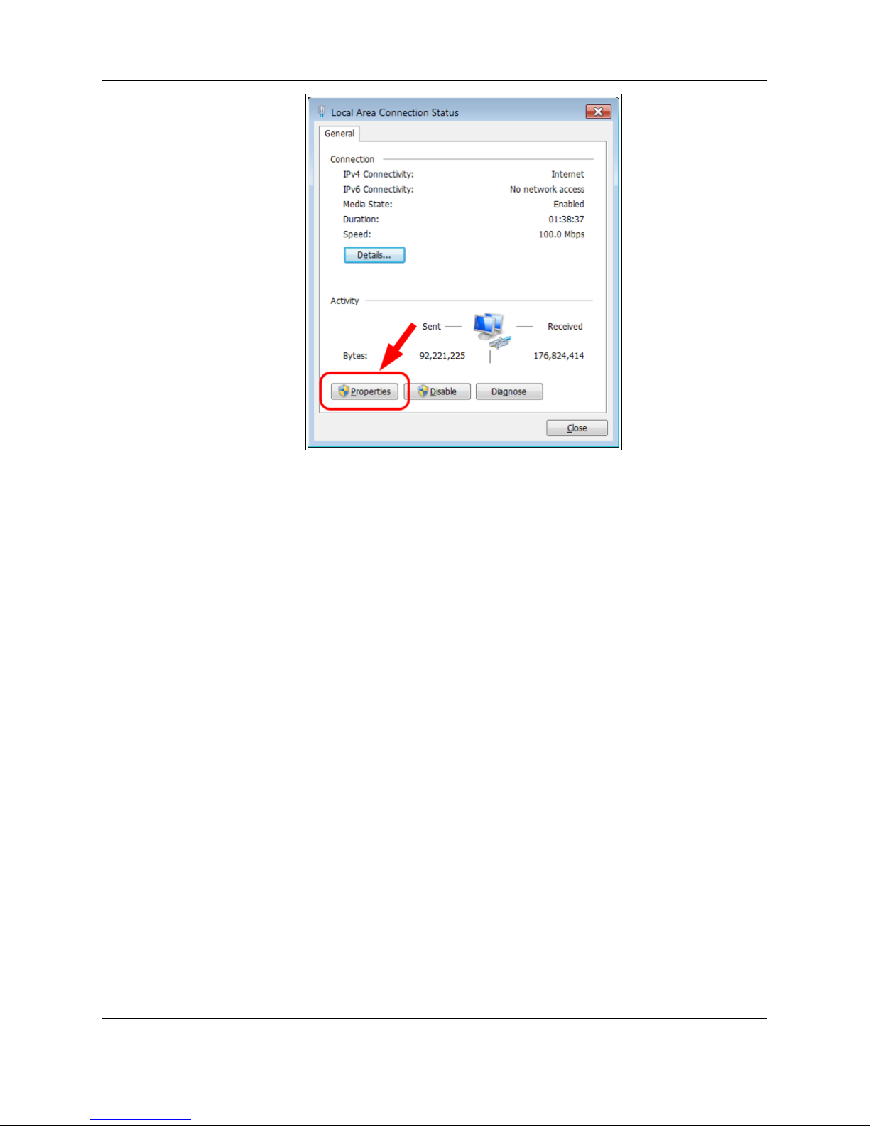
3. Click the Change Adapter Settings link.
Figure 66: Change Adapter Settings Link
4. Double-click the Local Area Connection link.
Figure 67: Local Area Connection Link
The Local Area Connection Status dialog box opens.
LUM0076AA Rev Jul-2017 Page 47 of 171
This document is the property of FreeWave Technologies, Inc. and contains proprietary information owned by
FreeWave. This document cannot be reproduced in whole or in part by any means without written permission from
FreeWave Technologies, Inc.
Page 48
8. Firmware Upgrade - Web Interface
Figure 68: Local Area Connection Status dialog box
5. Click Properties.
The Local Area Connection Properties dialog box opens.
6. Select the Internet Protocol Version 4 (TCP/IPv4) option.
Page 48 of 171 LUM0076AA Rev Jul-2017
This document is the property of FreeWave Technologies, Inc. and contains proprietary information owned by
FreeWave. This document cannot be reproduced in whole or in part by any means without written permission from
FreeWave Technologies, Inc.
Page 49

ZumLink™ Z9-P / Z9-PE: User Manual
Figure 69: Local Area Connection Properties dialog box
7. Click Properties.
The Internet Protocol Version 4 (TCP/IPv4) Properties dialog box opens.
8. Make a note of the current settings (to reverse this procedure later).
9. Select the Use the following IP address option button.
10. In the IP Address text box, enter an IP Address that is in the same subnet range but a
DIFFERENT IP Address than the ZumLink Z9-P / Z9-PE.
Example: Enter an IP Address from 192.168.111.1 to 192.168.111.254 (but NOT
192.168.111.100) and the Subnet Mask to 255.255.255.0.
Note: The default ZumLink IP Address is 192.168.111.100. The default subnet mask is
255.255.255.0.
LUM0076AA Rev Jul-2017 Page 49 of 171
This document is the property of FreeWave Technologies, Inc. and contains proprietary information owned by
FreeWave. This document cannot be reproduced in whole or in part by any means without written permission from
FreeWave Technologies, Inc.
Page 50

8. Firmware Upgrade - Web Interface
Figure 70: Local Area Connection Properties dialog box
Note: An IP Address is NOT required in the Default Gateway text box.
11. Click to save the changes and close the dialog box.
12. Click Close twice to close the Local Area Connection Properties and Local Area
Connection Status dialog boxes.
Page 50 of 171 LUM0076AA Rev Jul-2017
This document is the property of FreeWave Technologies, Inc. and contains proprietary information owned by
FreeWave. This document cannot be reproduced in whole or in part by any means without written permission from
FreeWave Technologies, Inc.
Page 51

ZumLink™ Z9-P / Z9-PE: User Manual
8.3. Install the Upgrade File using the Web Interface
Note: The images in this procedure are for Windows® 7 and/or Firefox®.
The dialog boxes and windows appear differently on each computer.
1. Using a CAT5e / CAT6 Ethernet cable, connect the ZumLink Z9-P / Z9-PE Ethernet port to
the Ethernet port on the computer.
2. Open a web browser.
3. In the URL address bar, enter the IP address of the attached ZumLink Z9-P / Z9-PE.
Note: If this is the first time accessing the radio, enter the default ZumLink Z9-P / Z9-PE IP
Address of 192.168.111.100.
If the IP Address was changed, enter that IP Address.
4. Refresh the browser window (press <F5>).
The Home window (on page 69) opens.
5. Click the File Upload link.
The Login dialog box opens.
6. Enter admin in both the User Name and Password text boxes and click OK.
The Login dialog box closes and the File Upload window opens.
Note: If the User Name or Password were changed, enter the applicable information in the
appropriate text box.
LUM0076AA Rev Jul-2017 Page 51 of 171
This document is the property of FreeWave Technologies, Inc. and contains proprietary information owned by
FreeWave. This document cannot be reproduced in whole or in part by any means without written permission from
Figure 71: Home window
FreeWave Technologies, Inc.
Page 52

8. Firmware Upgrade - Web Interface
Figure 72: ZumLink Z9-P / Z9-PE File Upload window
7. Click Browse.
The Microsoft® File Upload dialog box opens.
8. Locate and select the downloaded ZumLink upgrade .pkg file.
Figure 73: Microsoft® File Upload dialog box with the selected .pkg file
9. Click Open.
The dialog box closes and the ZumLink Z9-P / Z9-PE File Upload window returns showing
the selected file.
Figure 74: ZumLink Z9-P / Z9-PE File Upload window with selected .pkg file.
Page 52 of 171 LUM0076AA Rev Jul-2017
This document is the property of FreeWave Technologies, Inc. and contains proprietary information owned by
FreeWave. This document cannot be reproduced in whole or in part by any means without written permission from
FreeWave Technologies, Inc.
Page 53

ZumLink™ Z9-P / Z9-PE: User Manual
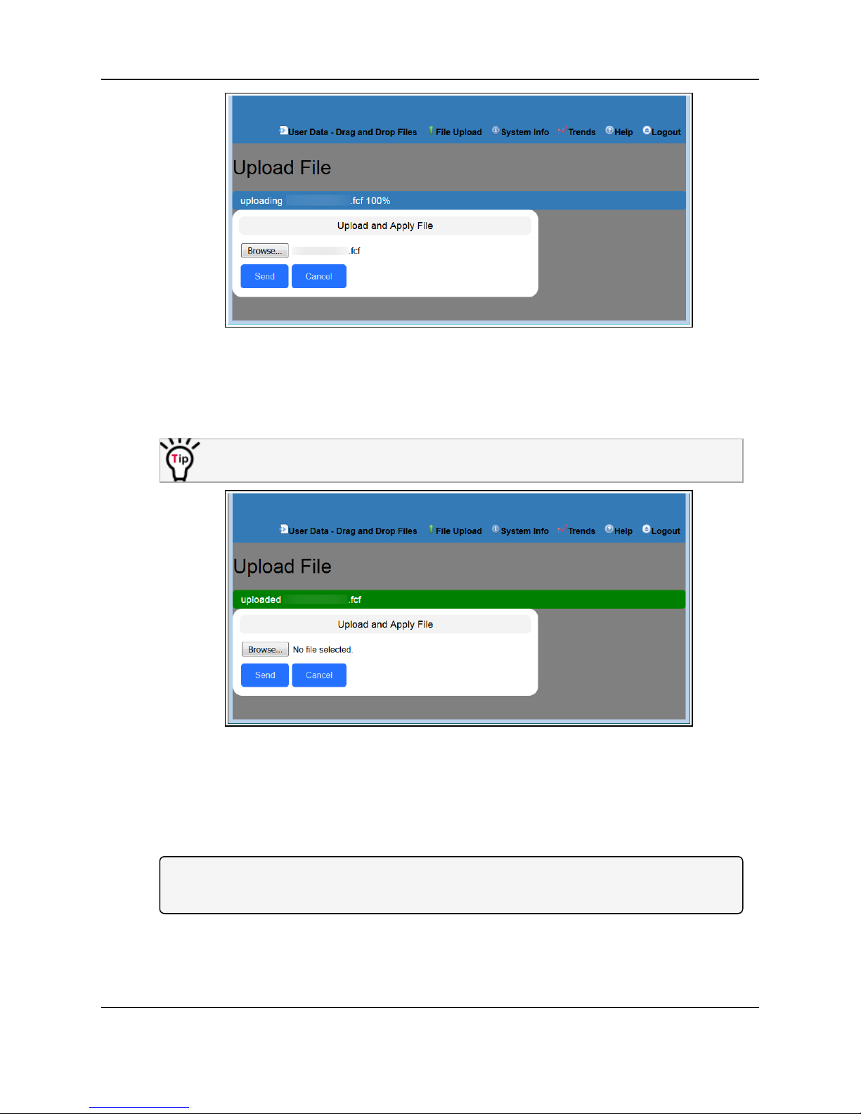
10. Click Send.
The File Upload window changes to show the completed upload percentage to the
ZumLink Z9-P / Z9-PE.
Figure 75: ZumLink Z9-P / Z9-PE File Upload window showing uploading
percentage.
11. Wait for the .pkg or .pkg.txt file to be applied (≈ 6-10 minutes).
The File Upload window refreshes and shows the completed and uploaded file applied to
the ZumLink Z9-P / Z9-PE.
Figure 76: ZumLink Z9-P / Z9-PE File Upload window showing completed
12. Click Browse.
The Microsoft® File Upload dialog box opens.
13. Locate and select the downloaded ZumLink upgrade .fcf file.
LUM0076AA Rev Jul-2017 Page 53 of 171
This document is the property of FreeWave Technologies, Inc. and contains proprietary information owned by
FreeWave. This document cannot be reproduced in whole or in part by any means without written permission from
upload of the selected file.
FreeWave Technologies, Inc.
Page 54

8. Firmware Upgrade - Web Interface
Figure 77: Microsoft® File Upload dialog box with the selected .fcf file
14. Click Open.
The dialog box closes and the ZumLink Z9-P / Z9-PE File Upload window returns showing
the selected file.
Figure 78: ZumLink Z9-P / Z9-PE File Upload window with selected .fcf file
15. Click Send.
The File Upload window changes to show the completed upload percentage to the
ZumLink Z9-P / Z9-PE.
Note: The .fcf file uploads very quickly (≈ 1-2 minutes).
The LEDs (on page 158) provide an indication of the upgrade process.
Page 54 of 171 LUM0076AA Rev Jul-2017
This document is the property of FreeWave Technologies, Inc. and contains proprietary information owned by
FreeWave. This document cannot be reproduced in whole or in part by any means without written permission from
FreeWave Technologies, Inc.
Page 55
ZumLink™ Z9-P / Z9-PE: User Manual
Figure 79: ZumLink Z9-P / Z9-PE File Upload window showing uploading
percentage.
The File Upload window refreshes and shows the completed and uploaded file applied to
the ZumLink Z9-P / Z9-PE.
The LEDs indicated the upgrade process. See LEDs (on page 158).
Figure 80: ZumLink Z9-P / Z9-PE File Upload window showing completed
16. Optional: Click the System Info link.
The System Info window opens showing the updated firmware on the ZumLink Z9-P / Z9PE.
Note: See the ZumLink Z9-P / Z9-PE Settings and Descriptions (on page 73) for detailed
information about the settings.
LUM0076AA Rev Jul-2017 Page 55 of 171
This document is the property of FreeWave Technologies, Inc. and contains proprietary information owned by
FreeWave. This document cannot be reproduced in whole or in part by any means without written permission from
upload of the selected file.
FreeWave Technologies, Inc.
Page 56

ZumLink™ Z9-P / Z9-PE: User Manual
9. Ports
This section identifies the ports of the ZumLink Z9-P / Z9-PE.
l Z9-P Ports (on page 56)
l Z9-PE Ports (on page 57)
l Serial and Ethernet Port Details (on page 57)
9.1. Z9-P Ports
LUM0076AA Rev Jul-2017 Page 56 of 171
This document is the property of FreeWave Technologies, Inc. and contains proprietary information owned by
FreeWave. This document cannot be reproduced in whole or in part by any means without written permission from
Figure 81: ZumLink Z9-P Ports
FreeWave Technologies, Inc.
Page 57

9. Ports
9.2. Z9-PE Ports
Figure 82: ZumLink Z9-PE Ports
9.3. Serial and Ethernet Port Details
Note: The RJ-45 Ethernet and the micro USB connectors are standard connectors with industry
standard pinout and signals. See the LEDs (on page 158) for additional information.
Figure 83: ZumLink Z9-P / Z9-PE Pin Location
Page 57 of 171 LUM0076AA Rev Jul-2017
This document is the property of FreeWave Technologies, Inc. and contains proprietary information owned by
FreeWave. This document cannot be reproduced in whole or in part by any means without written permission from
FreeWave Technologies, Inc.
Page 58

ZumLink™ Z9-P / Z9-PE: User Manual
ZumLink Z9-P / Z9-PE Serial Port Pinout Information
Pin Number RS-232 RS-485 RS422
1 -- -- --
2 CD --- (O) -- --
3 DTR --- (I) -- --
4 GND GND GND
5 RXD --- (I) -- TX+ (A+) --- (O)
6 TXD --- (O) RX+ (Y+) --- (B) RX+ (Y+) --- (I)
7 CTS --- (O) RX- (Z-) --- (B) RX- (Z-) --- (I)
8 RTS --- (I) -- TX- (B-) --- (O)
***Com1.mode=
Com2.mode=
RS232 RS485 RS485
***Com1.duplex=
Com2.duplex=
Half or Full Half Full
Note: The information in the table refers to the Serial Ports in Figure 83.
Note: ***See the ZumLink Z9-P / Z9-PE Settings and Descriptions - Com1 or Com2 (on page 74)
section for detailed information.
l (I) - Input
l (O) - Output
l (B) - Bidirectional
Important!: The RTS and CTS signals are NOT supported for COM1.
The RTS and CTS signals are ONLY available for COM2.
LUM0076AA Rev Jul-2017 Page 58 of 171
This document is the property of FreeWave Technologies, Inc. and contains proprietary information owned by
FreeWave. This document cannot be reproduced in whole or in part by any means without written permission from
FreeWave Technologies, Inc.
Page 59

ZumLink™ Z9-P / Z9-PE: User Manual
10. Mounting the ZumLink
Separate mounting kits are available for purchase from FreeWave.
l Z9-P FreeWave Part Number: AOH0001HT
l Z9-PE FreeWave Part Number: AOH4003SP
Mounting Procedures
l Z9-P Mounting (on page 60)
l Z9-PE Mounting (on page 61)
LUM0076AA Rev Jul-2017 Page 59 of 171
This document is the property of FreeWave Technologies, Inc. and contains proprietary information owned by
FreeWave. This document cannot be reproduced in whole or in part by any means without written permission from
FreeWave Technologies, Inc.
Page 60
10. Mounting the ZumLink
Z9-P - Included Equipment
Qty Description
1 DIN Rail Spring Clip
3 Flat-head machine screws, Phillips, M4 x 0.7, 12mm Long
1 DIN Rail Bracket
4 Pan-head machine screws, Phillips, 4-40, 1/4" Long, Lock Patch
1 Mounting Instruction Sheet
10.1. Z9-P Mounting
10.1.1. Included Equipment
User-supplied Equipment
l Medium Phillips-head screwdriver
l Medium Flat-head screwdriver
Procedure
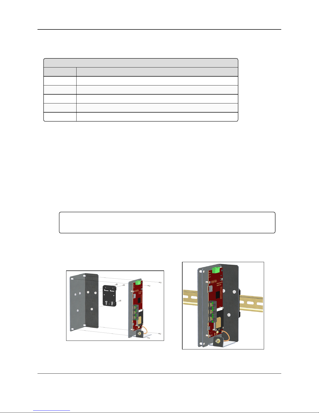
1. Use the Pan-head machine screws to attach the DIN Rail Bracket to the ZumLink.
2. Orient the DIN Rail Bracket / DIN Rail Spring Clip assembly so:
a. The spring-loaded end of the DIN Rail Spring Clip is on the bottom lip of the rail.
b. The fixed (not spring-loaded) end of the DIN Rail Spring Clip is on the top.
Important!: Per the manufacturer's instructions, the DIN Rail Spring Clip is oriented with
spring-loaded end on the bottom lip of the rail.
3. Use the Flat-head machine screws to attach the DIN Rail Spring Clip to the DIN Rail
Bracket.
4. Mount the ZumLink to the 35mm DIN rail using the rail slide on the enclosure.
Figure 84: Z9-P attached to a DIN rail with the power connection on top.
Page 60 of 171 LUM0076AA Rev Jul-2017
This document is the property of FreeWave Technologies, Inc. and contains proprietary information owned by
FreeWave. This document cannot be reproduced in whole or in part by any means without written permission from
FreeWave Technologies, Inc.
Page 61

ZumLink™ Z9-P / Z9-PE: User Manual
Z9-PE Mounting Kit - Included Equipment
Qty Description
1 DIN Rail Spring Clip
3 Flat-head machine screws, Phillips, M4 x 0.7, 12mm Long
1 DIN Rail Bracket
3 Pan-head machine screws, Phillips, 6-32 Unc, 1/4" Long
1 Mounting Instruction Sheet
10.2. Z9-PE Mounting
10.2.1. Included Equipment
User-supplied Equipment
l Medium Phillips-head screwdriver
l Medium Flat-head screwdriver
Procedure
1. Use the Pan-head machine screws to attach the DIN Rail Bracket to the ZumLink.
2. Decide the orientation of the ZumLink.
Note: The ZumLink can be mounted with either the power connection or antenna connection
at the top.
3. Orient the DIN Rail Bracket / DIN Rail Spring Clip assembly so:
a. The spring-loaded end of the DIN Rail Spring Clip is on the bottom lip of the rail.
b. The fixed (not spring-loaded) end of the DIN Rail Spring Clip is on the top.
Important!: Per the manufacturer's instructions, the DIN Rail Spring Clip is oriented with
spring-loaded end on the bottom lip of the rail.
4. Use the Flat-head machine screws to attach the DIN Rail Spring Clip to the DIN Rail
Bracket.
5. Mount the ZumLink to the 35mm DIN rail using the rail slide on the enclosure.
LUM0076AA Rev Jul-2017 Page 61 of 171
This document is the property of FreeWave Technologies, Inc. and contains proprietary information owned by
FreeWave. This document cannot be reproduced in whole or in part by any means without written permission from
FreeWave Technologies, Inc.
Page 62

10. Mounting the ZumLink
Figure 85: Z9-PE attached to a DIN rail with the power connection on top.
Figure 86: Z9-PE attached to a DIN rail with the antenna connection on top.
10.3. Removing the ZumLink from the DIN Rail
1. Push upwards on the DIN Rail Spring Clip (compressing the springs in the bottom).
2. Pivot the top of the DIN Rail Bracket / DIN Rail Spring Clip assembly off of the rail.
3. Move the whole DIN Rail Spring Clip down to release the bottom of the clip.
Page 62 of 171 LUM0076AA Rev Jul-2017
This document is the property of FreeWave Technologies, Inc. and contains proprietary information owned by
FreeWave. This document cannot be reproduced in whole or in part by any means without written permission from
FreeWave Technologies, Inc.
Page 63

ZumLink™ Z9-P / Z9-PE: User Manual
900MHz Omni-Directional Antennas
Gain (dBd) Gain (dBi) Manufacturer
Manufacturer
Model Number
FreeWave
Part Number
5.00 7.15 Antenex EB8965C EAN0905WC
3 5.15 Maxrad MAX-9053 EAN0900WC
-0.15 2.0 Mobile Mark PSKN3-925S EAN0900SR
-2.15 0 Mobile Mark PSTG0-915SE EAN0900SQ
8.35 10.5 Hana Wireless HW-OD9-11-NF
11. Approved Antennas
11.1. 900MHz Antennas
11.1.1. 900MHz Omni-Directional Antennas
The ZumLink 900MHz is approved by the FCC for use with omni-directional antennas with a
10.5dBi gain or less.
Note: These antennas, including antenna gains, are approved for use with the ZumLink device.
LUM0076AA Rev Jul-2017 Page 63 of 171
This document is the property of FreeWave Technologies, Inc. and contains proprietary information owned by
FreeWave. This document cannot be reproduced in whole or in part by any means without written permission from
FreeWave Technologies, Inc.
Page 64

11. Approved Antennas
900MHz Directional Antennas
Gain (dBd) Gain (dBi) Manufacturer
Manufacturer
Model Number
FreeWave
Part Number
5.85 8.0 WaveLink PRO898-8
6.45 8.6 WaveLink PRO890-8-40F02N4 EAN0906YC
13.85 16.0 WaveLink PRO890‐16‐40F02N4
11.1.2. 900MHz Directional Antennas
The ZumLink 900MHz is approved by the FCC for use with Yagi directional antennas with a
16.0dBi gain or less.
11.1.3. Alternative Antennas
Antennas other than those listed in this section can potentially be used with the ZumLink with
provisions.
l The antennas must be of a similar type.
l The antenna gain CANNOT exceed 10.5dBi for Omni-directional.
l The antenna gain CANNOT exceed 16.0dBi for Directional antennas.
l The overall system EIRP does not exceed 36dBm.
Warning! A proper combination with the ZumLink is required to ensure the system meets FCC
requirements.
Page 64 of 171 LUM0076AA Rev Jul-2017
This document is the property of FreeWave Technologies, Inc. and contains proprietary information owned by
FreeWave. This document cannot be reproduced in whole or in part by any means without written permission from
FreeWave Technologies, Inc.
Page 65

ZumLink™ Z9-P / Z9-PE: User Manual
12. ZumLink Z9-P / Z9-PE Web Interface
The ZumLink Z9-P / Z9-PE has a web interface used to:
l Drag and drop a customized configuration (.cfg) file
l Search the ZumLink Z9-P / Z9-PE Help information.
l Upgrade the firmware on the ZumLink Z9-P / Z9-PE.
l View System information
l View Trends
These windows are available to view information, complete a firmware upgrade, and change the
configuration of the ZumLink Z9-P / Z9-PE:
l File Upload window (on page 66)
l Help window (on page 68)
l Home window (on page 69)
l System Info window (on page 70)
l User Data - Drag and Drop window (on page 72)
LUM0076AA Rev Jul-2017 Page 65 of 171
This document is the property of FreeWave Technologies, Inc. and contains proprietary information owned by
FreeWave. This document cannot be reproduced in whole or in part by any means without written permission from
FreeWave Technologies, Inc.
Page 66

12. ZumLink Z9-P / Z9-PE Web Interface
Extension File Type
.cfg; .cfg.txt Configuration changes
.fcf; .fcf.txt Radio module firmware updates
.pkg; .pkg.txt Interface board Firmware updates
12.1. File Upload window
The File Upload window is used to search for and upload these file types:
Access and Window Description
1. Open a web browser.
2. In the URL address bar, enter the IP address of the attached ZumLink Z9-P / Z9-PE.
Note: If this is the first time accessing the radio, enter the default ZumLink Z9-P / Z9-PE IP
Address of 192.168.111.100.
If the IP Address was changed, enter that IP Address.
3. Refresh the browser window (press <F5>).
The Home window (on page 69) opens.
4. Click the File Upload link.
The Login dialog box opens.
5. Enter admin in both the User Name and Password text boxes and click OK.
The Login dialog box closes and the File Upload window opens.
Note: If the User Name or Password were changed, enter the applicable information in the
appropriate text box.
Figure 87: ZumLink Z9-P / Z9-PE File Upload window
Page 66 of 171 LUM0076AA Rev Jul-2017
This document is the property of FreeWave Technologies, Inc. and contains proprietary information owned by
FreeWave. This document cannot be reproduced in whole or in part by any means without written permission from
FreeWave Technologies, Inc.
Page 67

ZumLink™ Z9-P / Z9-PE: User Manual
File Upload window
Control Title Control Description
Browse button Click to open the Microsoft® File Upload dialog box.
Note: The Browse button title is dependent on the chosen browser.
Send button Click to start the upgrade process in the ZumLink Z9-P / Z9-PE.
Cancel button Click to cancel the file transfer if the transfer is already started or refresh the
window and clear the selected file.
LUM0076AA Rev Jul-2017 Page 67 of 171
This document is the property of FreeWave Technologies, Inc. and contains proprietary information owned by
FreeWave. This document cannot be reproduced in whole or in part by any means without written permission from
FreeWave Technologies, Inc.
Page 68

12. ZumLink Z9-P / Z9-PE Web Interface
12.2. Help window
The Help window is used to read information about the settings of the ZumLink Z9-P / Z9-PE.
Access and Window Description
1. Open a web browser.
2. In the URL address bar, enter the IP address of the attached ZumLink Z9-P / Z9-PE.
Note: If this is the first time accessing the radio, enter the default ZumLink Z9-P / Z9-PE IP
Address of 192.168.111.100.
If the IP Address was changed, enter that IP Address.
3. Refresh the browser window (press <F5>).
The Home window (on page 69) opens.
4. Click the Help link.
The Login dialog box opens.
5. Enter admin in both the User Name and Password text boxes and click OK.
The Login dialog box closes and the Help window opens.
Note: If the User Name or Password were changed, enter the applicable information in the
appropriate text box.
Note: The information in this window is read-only.
Page 68 of 171 LUM0076AA Rev Jul-2017
This document is the property of FreeWave Technologies, Inc. and contains proprietary information owned by
FreeWave. This document cannot be reproduced in whole or in part by any means without written permission from
Figure 88: Help window
FreeWave Technologies, Inc.
Page 69

ZumLink™ Z9-P / Z9-PE: User Manual
12.3. Home window
The Home window is the default window when ZumLink Z9-P / Z9-PE is opened in a web
browser.
It is used to:
l View basic System information of the connected ZumLink Z9-P / Z9-PE.
l Provide links to other windows of the ZumLink Z9-P / Z9-PE.
Access and Window Description
1. Open a web browser.
2. In the URL address bar, enter the IP address of the attached ZumLink Z9-P / Z9-PE.
Note: If this is the first time accessing the radio, enter the default ZumLink Z9-P / Z9-PE IP
Address of 192.168.111.100.
If the IP Address was changed, enter that IP Address.
3. Refresh the browser window (press <F5>).
The ZumLink Z9-P / Z9-PE Home window opens.
Note: See the ZumLink Z9-P / Z9-PE Settings and Descriptions (on page 73) for detailed
information about the settings.
Note: The information in this window is read-only.
LUM0076AA Rev Jul-2017 Page 69 of 171
This document is the property of FreeWave Technologies, Inc. and contains proprietary information owned by
FreeWave. This document cannot be reproduced in whole or in part by any means without written permission from
Figure 89: Home window
FreeWave Technologies, Inc.
Page 70

12. ZumLink Z9-P / Z9-PE Web Interface
12.4. System Info window
The System Info window allows the user to explore settings organized by page of the connected
ZumLink Z9-P / Z9-PE.
This is a visual representation of each setting.
The pages are the same as in the CLI.
Note: The information in this window is read-only.
See the ZumLink Z9-P / Z9-PE Settings and Descriptions (on page 73) for information about the other
available windows.
Access and Window Description
1. Open a web browser.
2. In the URL address bar, enter the IP address of the attached ZumLink Z9-P / Z9-PE.
Note: If this is the first time accessing the radio, enter the default ZumLink Z9-P / Z9-PE IP
Address of 192.168.111.100.
If the IP Address was changed, enter that IP Address.
3. Refresh the browser window (press <F5>).
The Home window (on page 69) opens.
4. Click the System Info link.
The Login dialog box opens.
5. Enter admin in both the User Name and Password text boxes and click OK.
The Login dialog box closes and the System Info window opens.
Page 70 of 171 LUM0076AA Rev Jul-2017
This document is the property of FreeWave Technologies, Inc. and contains proprietary information owned by
FreeWave. This document cannot be reproduced in whole or in part by any means without written permission from
FreeWave Technologies, Inc.
Page 71

ZumLink™ Z9-P / Z9-PE: User Manual
Figure 90: System Info window
LUM0076AA Rev Jul-2017 Page 71 of 171
This document is the property of FreeWave Technologies, Inc. and contains proprietary information owned by
FreeWave. This document cannot be reproduced in whole or in part by any means without written permission from
FreeWave Technologies, Inc.
Page 72
12. ZumLink Z9-P / Z9-PE Web Interface
12.5. User Data - Drag and Drop window
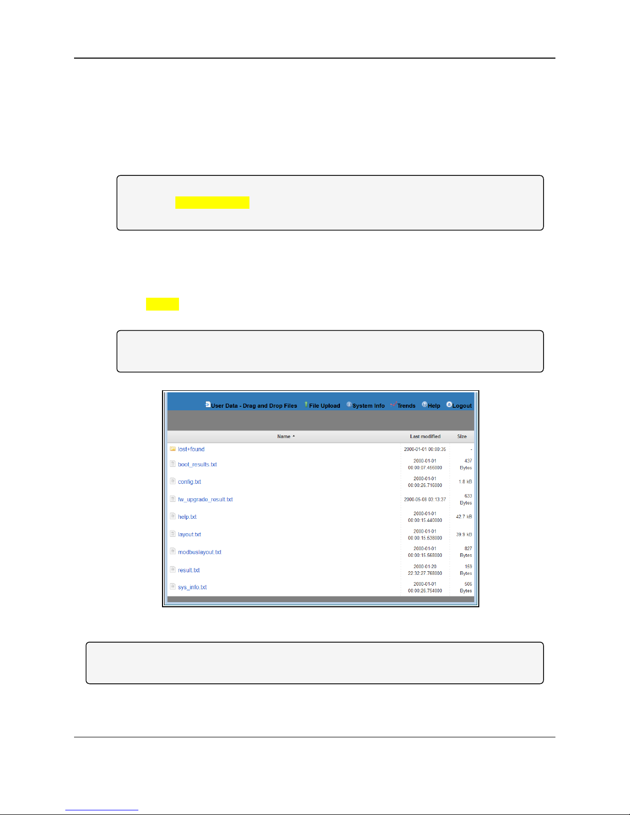
The User Data - Drag and Drop window lists the default files of the ZumLink Z9-P / Z9-PE.
Access and Window Description
1. Open a web browser.
2. In the URL address bar, enter the IP address of the attached ZumLink Z9-P / Z9-PE.
Note: If this is the first time accessing the radio, enter the default ZumLink Z9-P / Z9-PE IP
Address of 192.168.111.100.
If the IP Address was changed, enter that IP Address.
3. Refresh the browser window (press <F5>).
The Home window (on page 69) opens.
4. Click the User Data - Drag and Drop link.
The Login dialog box opens.
5. Enter admin in both the User Name and Password text boxes and click OK.
The Login dialog box closes and the User Data - Drag and Drop window opens.
Note: If the User Name or Password were changed, enter the applicable information in the
appropriate text box.
Figure 91: User Data - Drag and Drop window
Note: See the ZumLink Z9-P / Z9-PE Files and Descriptions (on page 161) for detailed information
about these files.
Page 72 of 171 LUM0076AA Rev Jul-2017
This document is the property of FreeWave Technologies, Inc. and contains proprietary information owned by
FreeWave. This document cannot be reproduced in whole or in part by any means without written permission from
FreeWave Technologies, Inc.
Page 73

13. ZumLink Z9-P / Z9-PE Settings and Descriptions
l Com1 or Com2 (on page 74)
l config (on page 82)
l dataPath (on page 84)
l date (on page 87)
l encryption (on page 90)
l localDiagnostics (on page 93)
l network (on page 101)
l networkStats (on page 106)
l ntp (on page 109)
l radioSettings (on page 111)
l radioSettingsHelpers(on page 129)
l services (on page 130)
l SNMP (on page 131)
l system (on page 135)
l systemInfo (on page 138)
Note: If the "=" sign is appended to the parameter, it is an implied change to that parameter.
If a value is NOT included after the "=", the value becomes a null, space, or 0 (zero) depending on the parameter.
Example: Entering frequencyKey returns the current value of frequencyKey.
Entering frequencyKey= is an implied change to frequencyKey.
If a value is NOT included, it changes frequencyKey to 0 (zero).
LUM0076AA Rev Jul-2017 Page 7 3 of 17 1
This docu ment is the property of FreeWave Technologies, Inc. and con tains proprietary information owned by FreeWave. This document cannot be reproduced
in wh ole or in part by a ny means witho ut written p ermission from FreeWave Technologies, Inc.
Page 74

13. ZumLinkZ9-P / Z9-PE Settings and Descriptions
Page 7 4 of 17 1 LUM0076AA Rev Jul-201 7
This docu ment is the property of FreeWave Technologies, Inc. and con tains proprietary information owned by FreeWave. This document cannot be reproduced
in wh ole or in part by a ny means witho ut written p ermission from FreeWave Technologies, Inc.
Com1 or Com2
Note: The table lists the full CLI Command first and then the Web GUI text box title.
The Web GUI text box is read-only and cannot be changed.
See CLI Configuration (on page 20) to access the CLI and change the settings.
Com1 or Com2 - ZumLink Settings and Descriptions
Page
CLI Command
Web GUI text box
Description
[Page=Com1]
[Page=Com2]
Com1.baudrate
Com2.baudrate
Baudrate
The Com1.baudrate or Com2.baudrate setting designates the COM port baud
rate for COM1 or COM2.
Options for Com1.baudrate= or Com2.baudrate=
1200 38400
2400 57600
4800 115200
9600 230400
14400 250000
19200
Note: The default value is 115200.
Page 75

ZumLink™ Z9-P / Z9-PE
Com1 or Com2 - ZumLink Settings and Descriptions
Page
CLI Command
Web GUI text box
Description
[Page=Com1]
[Page=Com2]
Com1.breakBeforeSendUs
Com2.breakBeforeSendUs
Break Before Send Us
The Com1.breakBeforeSendUs or Com2.breakBeforeSendUs setting
designates how long the COM port will send a break signal for at least the
number of microseconds specified before sending the data.
l The maximum value is 0 (zero).
l The minimum value is 1000.
The command is:
l
Com1.breakBeforeSendUs=nnnn
l
Com2.breakBeforeSendUs=nnnn
Example: For COM1, enter Com1.breakBeforeSendUs=500 to have
the COM1 port send a break signal for 500microseconds.
Note: The default value is 0 (zero).
[Page=Com1]
[Page=Com2]
Com1.ConectionDrops
Com2.ConectionDrops
Connection Drops
The Com1.ConectionDrops or Com2.ConectionDrops command reports the
number of terminal server connections dropped due to inactivity.
The command is:
l
Com1.ConectionDrops
l
Com2.ConectionDrops
Note: This is a Read-only parameter.
LUM0076AA Rev Jul-2017 Page 7 5 of 17 1
This docu ment is the property of FreeWave Technologies, Inc. and con tains proprietary information owned by FreeWave. This document cannot be reproduced
in wh ole or in part by a ny means witho ut written p ermission from FreeWave Technologies, Inc.
Page 76

13. ZumLinkZ9-P / Z9-PE Settings and Descriptions
Page 7 6 of 17 1 LUM0076AA Rev Jul-201 7
This docu ment is the property of FreeWave Technologies, Inc. and con tains proprietary information owned by FreeWave. This document cannot be reproduced
in wh ole or in part by a ny means witho ut written p ermission from FreeWave Technologies, Inc.
Com1 or Com2 - ZumLink Settings and Descriptions
Page
CLI Command
Web GUI text box
Description
[Page=Com1]
[Page=Com2]
Com1.databits
Com2.databits
Databits
The Com1.databits or Com2.databits setting designates the number of data
bits in the frame for COM1 or COM2.
The command is:
l Com1.databits=7 Com2.databits=7
l Com1.databits=8 Com2.databits=8
Note: The default value is 8.
[Page=Com1]
[Page=Com2]
Com1.delayBeforeSendMs
Com2.delayBeforeSendMs
Delay Before Send MS
The Com1.delayBeforeSendMs or Com2.delayBeforeSendMs setting
designates the amount of time delay (in ms) the ZumLink waits to allow the
device connected to the COM port to switch from transmit (Tx) to receive (Rx)
mode.
l The maximum value is 0 (zero).
l The minimum value is 5000.
The command is:
l
Com1.delayBeforeSendMs=nnnn
l
Com2.delayBeforeSendMs=nnnn
Example: For COM1, enter Com1.delayBeforeSendMs=100 for a
100 millisecond delay.
Increase this delay if the ZumLink is responding before a polling
system is ready for a response.
Note: The default value is 0 (zero).
Page 77

ZumLink™ Z9-P / Z9-PE
Com1 or Com2 - ZumLink Settings and Descriptions
Page
CLI Command
Web GUI text box
Description
[Page=Com1]
[Page=Com2]
Com1.duplex
Com2.duplex
Duplex
Important!: This setting ONLY applies to the RS-485 mode.
The Com1.duplex or Com2.duplex setting designates whether the COM port is
Full or Half duplex.
The command is:
l Com1.duplex=Half Com2.duplex=Half
l Com1.duplex=Full Com2.duplex=Full
Note: See Ports (on page 56) for input and output information.
Note: The default value is Full.
[Page=Com1]
[Page=Com2]
Com1.flowControl
Com2.flowControl
Flow Control
Important!: The RTS and CTS signals are NOT supported for COM1.
The RTS and CTS signals are ONLY available for COM2.
The Com2.flowControl setting designates the hardware flow control as either
on or off.
For Com2, the command is:
l Off: Com2.flowControl=Off
l On: Com2.flowControl=Hardware
Note: The default value is Off.
LUM0076AA Rev Jul-2017 Page 7 7 of 17 1
This docu ment is the property of FreeWave Technologies, Inc. and con tains proprietary information owned by FreeWave. This document cannot be reproduced
in wh ole or in part by a ny means witho ut written p ermission from FreeWave Technologies, Inc.
Page 78

13. ZumLinkZ9-P / Z9-PE Settings and Descriptions
Page 7 8 of 17 1 LUM0076AA Rev Jul-201 7
This docu ment is the property of FreeWave Technologies, Inc. and con tains proprietary information owned by FreeWave. This document cannot be reproduced
in wh ole or in part by a ny means witho ut written p ermission from FreeWave Technologies, Inc.
Com1 or Com2 - ZumLink Settings and Descriptions
Page
CLI Command
Web GUI text box
Description
[Page=Com1]
[Page=Com2]
Com1.handler
Com2.handler
Handler
The Com1.handler or Com2.handler setting designates the protocol of the
COM port as CLI, Terminal Server, or Trace.
The command is:
CLI
The command is:
l
Com1.handler=cli
l
Com2.handler=cli
Terminal Server
A configuration CLI is on the COM port.
l Com1.handler=TerminalServer
Com2.handler=TerminalServer
Notes
l The COM port will act as a terminal server.
l The TCP port number is determined by the COM TerminalServerPort
setting.
l The default port number for COM1 is 5041.
l The default port number for COM2 is 5042.
Trace
A configuration CLI with trace is on the COM port.
l
Com1.handler=trace
l
Com2.handler=trace
Note: The default value is TerminalServer.
Page 79
ZumLink™ Z9-P / Z9-PE
Com1 or Com2 - ZumLink Settings and Descriptions
Page
CLI Command
Web GUI text box
Description
[Page=Com1]
[Page=Com2]
Com1.mode
Com2.mode
Mode
The Com1.mode or Com2.mode setting designates the COM port mode as
either RS232 or RS485.
The command is:
l Com1.mode=RS232 Com2.mode=RS232
l Com1.mode=RS485 Com2.mode=RS485
Note: The default value is RS232.
Note: When Com1.mode=RS485 or Com2.mode=RS485
AND Com1.duplex=Full or Com2.duplex=Full,
the COM supports RS422.
[Page=Com1]
[Page=Com2]
Com1.parity
Com2.parity
Parity
The Com1.parity or Com2.paritysetting designates the COM port parity bits
for the system.
The command is:
l Com1.parity=None Com2.parity=None
l Com1.parity=Even Com2.parity=Even
l Com1.parity=Odd Com2.parity=Odd
Note: The default value is None.
LUM0076AA Rev Jul-2017 Page 7 9 of 17 1
This docu ment is the property of FreeWave Technologies, Inc. and con tains proprietary information owned by FreeWave. This document cannot be reproduced
in wh ole or in part by a ny means witho ut written p ermission from FreeWave Technologies, Inc.
Page 80

13. ZumLinkZ9-P / Z9-PE Settings and Descriptions
Page 8 0 of 17 1 LUM0076AA Rev Jul-201 7
This docu ment is the property of FreeWave Technologies, Inc. and con tains proprietary information owned by FreeWave. This document cannot be reproduced
in wh ole or in part by a ny means witho ut written p ermission from FreeWave Technologies, Inc.
Com1 or Com2 - ZumLink Settings and Descriptions
Page
CLI Command
Web GUI text box
Description
[Page=Com1]
[Page=Com2]
Com1.RxBytes
Com2.RxBytes
RX Bytes
The Com1.RxBytes or Com2.RxBytes command reports the total bytes
received from the COM port.
The command is:
l
Com1.RxBytes
l
Com2.RxBytes
Note: This is a Read-only parameter.
[Page=Com1]
[Page=Com2]
Com1.stopbits
Com2.stopbits
Stopbits
The Com1.stopbits or Com2.stopbits setting designates the COM port number
of stop bits.
The command is:
l Com1.stopbits=1 Com2.stopbits=1
l Com1.stopbits=2 Com2.stopbits=2
Note: The default value is 1.
[Page=Com1]
[Page=Com2]
Com1.TerminalServerPort
Com2.TerminalServerPort
Terminal ServerPort
The Com1.TerminalServerPort or Com2.TerminalServerPort setting
designates the TCP port number.
l The minimum value is 0 (zero).
l The maximum value is 65535.
The command is:
l
Com1.TerminalServerPort=nnn
l
Com2.TerminalServerPort=nnn
Note: The default port number for COM1 is 5041.
The default port number for COM2 is 5042.
Page 81
ZumLink™ Z9-P / Z9-PE
Com1 or Com2 - ZumLink Settings and Descriptions
Page
CLI Command
Web GUI text box
Description
[Page=Com1]
[Page=Com2]
Com1.TerminalServerTimeOut
Com2.TerminalServerTimeOut
Terminal ServerTime Out
The Com1.TerminalServerTimeOut or Com2.TerminalServerTimeOut
setting designates the amount of time, in seconds, the Terminal Server remains
open without data being received from the network.
l The minimum value is 0 (zero).
l The maximum value is 3600.
The command is:
l
Com1.TerminalServerTimeOut=nnn
l
Com2.TerminalServerTimeOut=nnn
Note: The default value is 300.
[Page=Com1]
[Page=Com2]
Com1.TxBytes
Com2.TxBytes
TX Bytes
The Com1.TxBytes or Com2.TxBytes command reports the total bytes sent
out of the COM port.
The command is:
l
Com1.TxBytes
l
Com2.TxBytes
Note: This is a Read-only parameter.
LUM0076AA Rev Jul-2017 Page 8 1 of 17 1
This docu ment is the property of FreeWave Technologies, Inc. and con tains proprietary information owned by FreeWave. This document cannot be reproduced
in wh ole or in part by a ny means witho ut written p ermission from FreeWave Technologies, Inc.
Page 82

13. ZumLinkZ9-P / Z9-PE Settings and Descriptions
Page 8 2 of 17 1 LUM0076AA Rev Jul-201 7
This docu ment is the property of FreeWave Technologies, Inc. and con tains proprietary information owned by FreeWave. This document cannot be reproduced
in wh ole or in part by a ny means witho ut written p ermission from FreeWave Technologies, Inc.
config
Note: The table lists the full CLI Command first and then the Web GUI text box title.
The Web GUI text box is read-only and cannot be changed.
See CLI Configuration (on page 20) to access the CLI and change the settings.
config - ZumLink Settings and Descriptions
Page
CLI Command
Web GUI text box
Description
[Page=config] config.addTraceMask
Add Trace Mask
Important!: FreeWave internal use only.
[Page=config] config.factoryDefaults
Factory Defaults
The config.factoryDefaultscommand restores the ZumLink to its factory default
configuration.
The command is: config.factoryDefaults=set
[Page=config] config.getCurrentConfig
Get Current Config
Important!: FreeWave internal use only.
[Page=config] config.handleDragDrop
Handle Drag Drop
Important!: FreeWave internal use only.
[Page=config] config.licenseState
License State
The config.licenseState command reports the extra feature licenses in the ZumLink
Z9-P / Z9-PE.
The command is: config.licenseState
Note: This is a Read-only parameter.
[Page=config] config.loadConfig
Load Config
Important!: FreeWave internal use only.
[Page=config] config.removeTraceMask
Remove Trace Mask
Important!: FreeWave internal use only.
Page 83

ZumLink™ Z9-P / Z9-PE
config - ZumLink Settings and Descriptions
Page
CLI Command
Web GUI text box
Description
[Page=config] config.reset
Reset
The config.reset command restarts or reboots the ZumLink Z9-P / Z9-PE.
The command is:
l Reboot the entire ZumLink device:
l
config.reset=now
l
config.reset=reboot
l Restart to reset the main application:
l
config.reset=reset
[Page=config] config.restore
Restore
The config.restore command reloads a previously saved setting configurationof the
ZumLink.
The command is:
l
config.restore=now
l
config.restore
l
restore
Note: Restore happens automatically when the ZumLink starts.
[Page=config] config.save
Save
The config.savecommand saves changes made to the ZumLink configuration.
The command is:
l
config.save=now
l
config.save
l
save
LUM0076AA Rev Jul-2017 Page 8 3 of 17 1
This docu ment is the property of FreeWave Technologies, Inc. and con tains proprietary information owned by FreeWave. This document cannot be reproduced
in wh ole or in part by a ny means witho ut written p ermission from FreeWave Technologies, Inc.
Page 84

13. ZumLinkZ9-P / Z9-PE Settings and Descriptions
Page 8 4 of 17 1 LUM0076AA Rev Jul-201 7
This docu ment is the property of FreeWave Technologies, Inc. and con tains proprietary information owned by FreeWave. This document cannot be reproduced
in wh ole or in part by a ny means witho ut written p ermission from FreeWave Technologies, Inc.
dataPath
Note: The table lists the full CLI Command first and then the Web GUI text box title.
The Web GUI text box is read-only and cannot be changed.
See CLI Configuration (on page 20) to access the CLI and change the settings.
dataPath - ZumLink Settings and Descriptions
Page
CLI Command
Web GUI text box
Description
[Page=dataPath] dataPath.aggregateEnabled
Aggregate Enabled
The dataPath.aggregateEnabled setting enables the aggregation of smaller
packets to enhance throughput.
Notes
l Packets below 900 bytes are aggregated up to an aggregated packet size of
970 bytes.
l There is a 20 msec aggregation window - if another packet is not received
within 20 msec, the aggregated packet is transmitted.
FREEWAVE Recommends: Enable this setting when the network
data packets are small.
The command is:
l Enable: dataPath.aggregateEnabled=true
l Disable: dataPath.aggregateEnabled=false
Note: The default value is false.
Page 85

ZumLink™ Z9-P / Z9-PE
dataPath - ZumLink Settings and Descriptions
Page
CLI Command
Web GUI text box
Description
[Page=dataPath] dataPath.compressionEnabled
Compression Enabled
When the dataPath.compressionEnabled setting is enabled, the outgoing
packets are sent compressed if the data packet can be compressed.
Note: The compression ratio is dependent on the data redundancy.
The command is:
l Enable: dataPath.compressionEnabled=true
l Disable: dataPath.compressionEnabled=false
Note: The default value is false.
[Page=dataPath] dataPath.fecRate
FEC Rate
The dataPath.fecRate setting enables the FEC (Forward Error Correction) rate.
Note: FEC increases the reliability of the data transferred over the air at
the cost of some transmission throughput.
The command is:
l Enable: dataPath.fecRate=RATE_7_8
l Enables FEC with a packet overhead of about 13%.
l Improves sensitivity.
l Adds resilience in noisy environments.
l Disable: dataPath.fecRate=RATE_1_1
Note: The default value is RATE_1_1
LUM0076AA Rev Jul-2017 Page 8 5 of 17 1
This docu ment is the property of FreeWave Technologies, Inc. and con tains proprietary information owned by FreeWave. This document cannot be reproduced
in wh ole or in part by a ny means witho ut written p ermission from FreeWave Technologies, Inc.
Page 86

13. ZumLinkZ9-P / Z9-PE Settings and Descriptions
Page 8 6 of 17 1 LUM0076AA Rev Jul-201 7
This docu ment is the property of FreeWave Technologies, Inc. and con tains proprietary information owned by FreeWave. This document cannot be reproduced
in wh ole or in part by a ny means witho ut written p ermission from FreeWave Technologies, Inc.
dataPath - ZumLink Settings and Descriptions
Page
CLI Command
Web GUI text box
Description
[Page=dataPath] dataPath.otaMaxFragmentSize
OTA Max Fragment Size
The dataPath.otaMaxFragmentSize setting designates the maximum
fragment size sent over the air.
Packets larger than the maxPacketSize are fragmented into smaller packets
whose size is determined by the otaMaxFragementSize.
l The minimum value is 64.
l The maximum value is 1000.
A smaller number may give better performance in a high
interference environment.
A larger number can increase throughput.
The command is:
l
dataPath.otaMaxFragmentSize=nnnn
Note: The default value is 1000.
Page 87
ZumLink™ Z9-P / Z9-PE
date
Important!: Time zones do not apply on the ZumLink.
Note: The table lists the full CLI Command first and then the Web GUI text box title.
The Web GUI text box is read-only and cannot be changed.
See CLI Configuration (on page 20) to access the CLI and change the settings.
The information in the table is read-only.
date - ZumLink Settings and Descriptions
Page
CLI Command
Web GUI text box
Description
[Page=date] date.dcAppStartTime
DC App Start Time
The date.dcAppStartTime command reports the time stamp of when the main app
restarted.
The command is:
l
date.dcAppStartTime
l
dcAppStartTime
Note: This is a Read-only parameter.
[Page=date] date.dcAppUptime
DC App Uptime
The date.dcAppUptime command reports the number of seconds since the main app
restarted.
The command is:
l
date.dcAppUptime
l
dcAppUptime
Note: This is a Read-only parameter.
LUM0076AA Rev Jul-2017 Page 8 7 of 17 1
This docu ment is the property of FreeWave Technologies, Inc. and con tains proprietary information owned by FreeWave. This document cannot be reproduced
in wh ole or in part by a ny means witho ut written p ermission from FreeWave Technologies, Inc.
Page 88
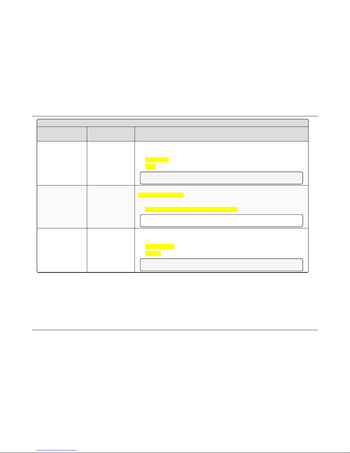
13. ZumLinkZ9-P / Z9-PE Settings and Descriptions
Page 8 8 of 17 1 LUM0076AA Rev Jul-201 7
This docu ment is the property of FreeWave Technologies, Inc. and con tains proprietary information owned by FreeWave. This document cannot be reproduced
in wh ole or in part by a ny means witho ut written p ermission from FreeWave Technologies, Inc.
date - ZumLink Settings and Descriptions
Page
CLI Command
Web GUI text box
Description
[Page=date] date.time
Time
The date.time command reports the current time in Unix timestamp format.
The command is:
l
date.time
l
time
Note: This is a Read-only parameter.
[Page=date] date.timeString
Time String
The date.timeString setting changes the time ONLY if the ntpReference is set to
REFCLK_LOCALCLOCK.
The command is:
l
date.timeString=MM/DD/YYYY HH.MM.SS
Important!: If the ZumLink loses power, the time must be manually reset.
[Page=date] date.upTime
Up Time
The date.upTime command reports the number of seconds since the ZumLink restarted.
The command is:
l
date.upTime
l
upTime
Note: This is a Read-only parameter.
Page 89
ZumLink™ Z9-P / Z9-PE
date - ZumLink Settings and Descriptions
Page
CLI Command
Web GUI text box
Description
[Page=date] date.upTimeString
Up Time String
The date.upTimeString command reports the amount of time in Days, Hours, Minutes,
and Seconds the ZumLink device has been powered on without a reboot.
The command is:
l
date.upTimeString
l
upTimeString
Example: A return of 5 01:36:41means the unit has been up for 5 days, 1 hour, 36
minutes, and41 seconds.
Note: This is a Read-only parameter.
LUM0076AA Rev Jul-2017 Page 8 9 of 17 1
This docu ment is the property of FreeWave Technologies, Inc. and con tains proprietary information owned by FreeWave. This document cannot be reproduced
in wh ole or in part by a ny means witho ut written p ermission from FreeWave Technologies, Inc.
Page 90

13. ZumLinkZ9-P / Z9-PE Settings and Descriptions
Page 9 0 of 17 1 LUM0076AA Rev Jul-201 7
This docu ment is the property of FreeWave Technologies, Inc. and con tains proprietary information owned by FreeWave. This document cannot be reproduced
in wh ole or in part by a ny means witho ut written p ermission from FreeWave Technologies, Inc.
encryption
Note: The table lists the full CLI Command first and then the Web GUI text box title.
The Web GUI text box is read-only and cannot be changed.
See CLI Configuration (on page 20) to access the CLI and change the settings.
encryption - ZumLink Settings and Descriptions
Page
CLI Command
Web GUI text box
Description
[Page=encryption] encryption.activeKey
Active Key
The encryption.activeKey setting designates the active key.
The command is:
l
encryption.activeKey=Off
l
encryption.activeKey=Key1 to Key16
Example: encryption.activeKey=Key10.
Note: The default value is Off.
[Page=encryption] encryption.encryptionMode
Encryption Mode
The encryption.encryptionModesetting designates the encryption mode.
The command is:
l AES Counter Mode:
l
encryption.encryptionMode=AES_CTR
l AES Counter Mode with MIC (Message Integrity Check):
l
encryption.encryptionMode=AES_CCM
Important!: Use of encryption may affect latency and user throughput.
Note: The default value is AES_CTR.
Page 91

ZumLink™ Z9-P / Z9-PE
encryption - ZumLink Settings and Descriptions
Page
CLI Command
Web GUI text box
Description
[Page=encryption] encryption.getKey
Get Key
The encryption.getKey command reports this information about the key:
l whetherthe key is 128- or 256-bit key.
l if the key is empty.
The command is:
l
encryption.getKey=Off
l
encryption.getKey=Key1 to Key16
Example: encryption.getKey=key8.
Note: This is a Read-only parameter.
[Page=encryption] encryption.remoteRestore
Important!: FreeWave internal use only.
[Page=encryption] encryption.remoteSave
Important!: FreeWave internal use only.
LUM0076AA Rev Jul-2017 Page 9 1 of 17 1
This docu ment is the property of FreeWave Technologies, Inc. and con tains proprietary information owned by FreeWave. This document cannot be reproduced
in wh ole or in part by a ny means witho ut written p ermission from FreeWave Technologies, Inc.
Page 92
13. ZumLinkZ9-P / Z9-PE Settings and Descriptions
Page 9 2 of 17 1 LUM0076AA Rev Jul-201 7
This docu ment is the property of FreeWave Technologies, Inc. and con tains proprietary information owned by FreeWave. This document cannot be reproduced
in wh ole or in part by a ny means witho ut written p ermission from FreeWave Technologies, Inc.
encryption - ZumLink Settings and Descriptions
Page
CLI Command
Web GUI text box
Description
[Page=encryption] encryption.setKey
Set Key
The encryption.setKeysetting loads the key.
The format of this setting is: setKey [key] [128 or 256 key in hex]
Example: 128 bit key:
encryption.setKey=key1 1234567890abcdef1234567890abcdef
Example: 256 bit key: encryption.setKey=key2
1234567890abcdef1234567890abcdef1234567890abcdef1234567890abcd
ef
Enter encryption.setKey= WITHOUT an actual key to erase or
clear the key.
Page 93
ZumLink™ Z9-P / Z9-PE
localDiagnostics
Important!: The localDiagnostics are read-only and aredependent upon the connected ZumLink.
Note: The table lists the full CLI Command first and then the Web GUI text box title.
The Web GUI text box is read-only and cannot be changed.
See CLI Configuration (on page 20) to access the CLI and change the settings.
localDiagnostics - ZumLink Settings and Descriptions
Page
CLI Command
Web GUI text box
Description
[Page=localDiagnostics] localDiagnostics.signalLevel
Signal Level
The localDiagnostics.signalLevel command reports the Signal Level
of the radio in dBm of the last received packet.
l This setting shows -128.00 if no packet has been received since the
stats were cleared.
l The default value is -128.00.
The command is:
l
localDiagnostics.signalLevel
l
signalLevel
Note: This is a Read-only parameter.
LUM0076AA Rev Jul-2017 Page 9 3 of 17 1
This docu ment is the property of FreeWave Technologies, Inc. and con tains proprietary information owned by FreeWave. This document cannot be reproduced
in wh ole or in part by a ny means witho ut written p ermission from FreeWave Technologies, Inc.
Page 94

13. ZumLinkZ9-P / Z9-PE Settings and Descriptions
Page 9 4 of 17 1 LUM0076AA Rev Jul-201 7
This docu ment is the property of FreeWave Technologies, Inc. and con tains proprietary information owned by FreeWave. This document cannot be reproduced
in wh ole or in part by a ny means witho ut written p ermission from FreeWave Technologies, Inc.
localDiagnostics - ZumLink Settings and Descriptions
Page
CLI Command
Web GUI text box
Description
[Page=localDiagnostics] localDiagnostics.signalMargin
Signal Margin
The localDiagnostics.signalMargin command reports the amount of
signal margin in dB the last received packet experienced.
Note: The signal margin is the difference betweenthe signal
level andthe receive sensitivity for the configured RF data rate.
The command is:
l
localDiagnostics.signalMargin
l
signalMargin
Note: This is a Read-only parameter.
[Page=localDiagnostics] localDiagnostics.cntBadBCC
CNT Bad BCC
Important!: FreeWave internal use only.
[Page=localDiagnostics] localDiagnostics.cntBadSync
CNT Bad Sync
Important!: FreeWave internal use only.
[Page=localDiagnostics] localDiagnostics.cntETX
CNT ETX
Important!: FreeWave internal use only.
[Page=localDiagnostics] localDiagnostics.cntSTX
CNT STX
Important!: FreeWave internal use only.
Page 95

ZumLink™ Z9-P / Z9-PE
localDiagnostics - ZumLink Settings and Descriptions
Page
CLI Command
Web GUI text box
Description
[Page=localDiagnostics] localDiagnostics.getStats
Get Stats
The localDiagnostics.getStats command reports the
localDiagnostics from the radio immediately.
The command is:
l
localDiagnostics.getStats
l
getStats
Note: A refresh of the localDiagnostics page is required to see
the updates.
This is a Read-only parameter.
[Page=localDiagnostics] localDiagnostics.interfaceBytesRx
Interface Bytes RX
Important!: FreeWave internal use only.
[Page=localDiagnostics] localDiagnostics.interfaceBytesTx
Interface Bytes TX
Important!: FreeWave internal use only.
[Page=localDiagnostics] localDiagnostics.interfaceDataRx
Interface Data RX
Important!: FreeWave internal use only.
[Page=localDiagnostics] localDiagnostics.interfaceDataTx
Interface Data TX
Important!: FreeWave internal use only.
[Page=localDiagnostics] localDiagnostics.MacTableShow
Mac Table Show
The localDiagnostics.MacTableShow command reports the MAC
address of device connected to the ZumLink device.
The command is:
l
localDiagnostics.MacTableShow
l
MacTableShow
Note: This is a Read-only parameter.
LUM0076AA Rev Jul-2017 Page 9 5 of 17 1
This docu ment is the property of FreeWave Technologies, Inc. and con tains proprietary information owned by FreeWave. This document cannot be reproduced
in wh ole or in part by a ny means witho ut written p ermission from FreeWave Technologies, Inc.
Page 96

13. ZumLinkZ9-P / Z9-PE Settings and Descriptions
Page 9 6 of 17 1 LUM0076AA Rev Jul-201 7
This docu ment is the property of FreeWave Technologies, Inc. and con tains proprietary information owned by FreeWave. This document cannot be reproduced
in wh ole or in part by a ny means witho ut written p ermission from FreeWave Technologies, Inc.
localDiagnostics - ZumLink Settings and Descriptions
Page
CLI Command
Web GUI text box
Description
[Page=localDiagnostics] localDiagnostics.monitoredNode
Monitored Node
The localDiagnostics.monitoredNode setting designates the Node
ID to be monitored and reported back by the
localDiagnostics.showNodeDiags command.
Use the showNodeDiags to view the receivedsignal
level (RSSI) of this node.
The command is:
l
localDiagnostics.monitoredNode=<Node ID here>
l
monitoredNode=<Node ID here>
Note: The default value is.
This is a Read-only parameter.
[Page=localDiagnostics] localDiagnostics.RadioAckTx
Radio Ack TX
Important!: FreeWave internal use only.
[Page=localDiagnostics] localDiagnostics.RadioBadAckRx
Radio Bad Ack RX
The localDiagnostics.RadioBadAckRx command reports the
number of received ACKs missed in unicast transmissions.
The command is:
l
localDiagnostics.RadioBadAckRx
l
RadioBadAckRx
Note: This is a Read-only parameter.
Page 97

ZumLink™ Z9-P / Z9-PE
localDiagnostics - ZumLink Settings and Descriptions
Page
CLI Command
Web GUI text box
Description
[Page=localDiagnostics] localDiagnostics.RadioBadCRC
Radio Bad CRC
The localDiagnostics.RadioBadCRC command reports the number
of radio packets received with data corruption.
The command is:
l
localDiagnostics.RadioBadAckRx
l
RadioBadAckRx
Note: This is a Read-only parameter.
[Page=localDiagnostics] localDiagnostics.RadioBadSync
Radio Bad Sync
The localDiagnostics.RadioBadSync command reports the number
of times beacons were lost and the Endpoint needed to re-synchronize
with the Gateway when radioHoppingMode=Hopping_On.
The command is:
l
localDiagnostics.RadioBadSync
l
RadioBadSync
Note: This is a Read-only parameter.
[Page=localDiagnostics] localDiagnostics.RadioContentionDrop
Radio Contention Drop
The localDiagnostics.RadioContentionDrop command reports the
number of times a transmission was backed-off due to contention on
the RF channel.
The command is:
l
localDiagnostics.RadioContentionDrop
l
RadioContentionDrop
Note: This is a Read-only parameter.
LUM0076AA Rev Jul-2017 Page 9 7 of 17 1
This docu ment is the property of FreeWave Technologies, Inc. and con tains proprietary information owned by FreeWave. This document cannot be reproduced
in wh ole or in part by a ny means witho ut written p ermission from FreeWave Technologies, Inc.
Page 98

13. ZumLinkZ9-P / Z9-PE Settings and Descriptions
Page 9 8 of 17 1 LUM0076AA Rev Jul-201 7
This docu ment is the property of FreeWave Technologies, Inc. and con tains proprietary information owned by FreeWave. This document cannot be reproduced
in wh ole or in part by a ny means witho ut written p ermission from FreeWave Technologies, Inc.
localDiagnostics - ZumLink Settings and Descriptions
Page
CLI Command
Web GUI text box
Description
[Page=localDiagnostics] localDiagnostics.RadioLLRx
Radio LL RX
The localDiagnostics.RadioLLRx command reports the number of
packets received over the air without data corruption.
The command is:
l
localDiagnostics.RadioLLRx
l
RadioLLRx
Note: This is a Read-only parameter.
[Page=localDiagnostics] localDiagnostics.RadioLLTx
Radio LL TX
The localDiagnostics.RadioLLTx command reports the number of
packets transmitted over the air.
The command is:
l
localDiagnostics.RadioLLRx
l
RadioLLRx
Note: This is a Read-only parameter.
[Page=localDiagnostics] localDiagnostics.RadioNoAckTx
Radio No Ack TX
Important!: FreeWave internal use only.
[Page=localDiagnostics] localDiagnostics.RadioReliableRx
Radio Reliable RX
Important!: FreeWave internal use only.
[Page=localDiagnostics] localDiagnostics.RadioReliableTx
Radio Reliable TX
Important!: FreeWave internal use only.
[Page=localDiagnostics] localDiagnostics.RadioRexmit
Radio Rexmit
Important!: FreeWave internal use only.
Page 99

ZumLink™ Z9-P / Z9-PE
localDiagnostics - ZumLink Settings and Descriptions
Page
CLI Command
Web GUI text box
Description
[Page=localDiagnostics] localDiagnostics.RadioRx
Radio RX
The localDiagnostics.RadioRx command reports the number of data
packets correctly received over the wireless RF link for this node.
The command is:
l
localDiagnostics.RadioRx
l
RadioRx
Note: This is a Read-only parameter.
[Page=localDiagnostics] localDiagnostics.RadioSendingDrop
Radio Sending Drop
Important!: FreeWave internal use only.
[Page=localDiagnostics] localDiagnostics.RadioTimedOut
Radio Timed Out
Important!: FreeWave internal use only.
[Page=localDiagnostics] localDiagnostics.RadioTooLong
Radio Too Long
Important!: FreeWave internal use only.
[Page=localDiagnostics] localDiagnostics.RadioTooShort
Radio Too Short
Important!: FreeWave internal use only.
[Page=localDiagnostics] localDiagnostics.RadioTx
Radio TX
The localDiagnostics.RadioTx command reports the number of data
packets scheduledto be transmitted.
The command is:
l
localDiagnostics.RadioTx
l
RadioTx
Note: This is a Read-only parameter.
[Page=localDiagnostics] localDiagnostics.resetsDetected
Resets Detected
Important!: FreeWave internal use only.
LUM0076AA Rev Jul-2017 Page 9 9 of 17 1
This docu ment is the property of FreeWave Technologies, Inc. and con tains proprietary information owned by FreeWave. This document cannot be reproduced
in wh ole or in part by a ny means witho ut written p ermission from FreeWave Technologies, Inc.
Page 100

13. ZumLinkZ9-P / Z9-PE Settings and Descriptions
Page 1 00 of 171 LUM0076AA Rev Jul-2017
This docu ment is the property of FreeWave Technologies, Inc. and con tains proprietary information owned by FreeWave. This document cannot be reproduced
in wh ole or in part by a ny means witho ut written p ermission from FreeWave Technologies, Inc.
localDiagnostics - ZumLink Settings and Descriptions
Page
CLI Command
Web GUI text box
Description
[Page=localDiagnostics] localDiagnostics.resetSent
Reset Sent
Important!: FreeWave internal use only.
[Page=localDiagnostics] localDiagnostics.resetStats
Reset Stats
The localDiagnostics.resetStats command resets the local
diagnostics.
The command is:
l
localDiagnostics.resetStats
l
resetStats
Note: This is a Read-only parameter.
[Page=localDiagnostics] localDiagnostics.showChannelDiags
Show Channel Diags
The localDiagnostics.showChannelDiags command reports the
received signal level (RSSI)andnodeID of the last packet received on
the displayed frequencies.
The command is:
l
localDiagnostics.showChannelDiags
l
showChannelDiags
Note: This is a Read-only parameter.
 Loading...