

Page 1

WC45i-GW-485 Modbus Gateway
User & Reference Manual
Part Number: LUM0086AA
Revision: Mar-2018
Page 2

Safety Information
The products described in this manual can fail in a variety of modes due to misuse, age, or malfunction and is not
designed or intended for used in systems requiring fail-safe performance, including life safety systems. Systems
with the products must be designed to prevent personal injury and property damage during product operation
and in the event of product failure.
Warning! Remove power before connecting or disconnecting the interface or RF cables.
FreeWave Technologies, Inc. warrants the FreeWave® WC45i-GW-485 Modbus Gateway (Product) that you
have purchased against defects in materials and manufacturing for a period of three years from the date of
shipment, depending on model number. In the event of a Product failure due to materials or workmanship,
FreeWave will, at its discretion, repair or replace the Product. For evaluation of Warranty coverage, return the
Product to FreeWave upon receiving a Return Material Authorization (RMA). The replacement product will
remain under warranty for 90 days or the remainder of the original product warranty period, whichever is longer.
IN NO EVENT WILL FREEWAVE TECHNOLOGIES, INC., ITS SUPPLIERS, OR ITS LICENSORS BE LIABLE FOR ANY DAMAGES ARISING
FROM THE USE OF OR INABILITY TO USE THIS PRODUCT. THIS INCLUDES BUSINESS INTERRUPTION, LOSS OF BUSINESS
INFORMATION, INABILITY TO ACCESS OR SEND COMMUNICATION OR DATA, PERSONAL INJURY OR DAMAGE, OR OTHER LOSS
WHICH MAY ARISE FROM THE USE OF THIS PRODUCT. THE WARRANTY IS EXCLUSIVE AND ALL OTHER WARRANTIES EXPRESS
OR IMPLIED, INCLUDING BUT NOT LIMITED TO ANY WARRANTIES OF MERCHANTABILITY OR FITNESS FOR A PARTICULAR USE
ARE EXPRESSLY DISCLAIMED.
FreeWave’s Warranty does not apply in the following circumstances:
1. If Product repair, adjustments, or parts replacements are required due to accident, neglect, or undue
physical, electrical, or electromagnetic stress.
2. If Product is used outside of FreeWave specifications as stated in the Product's data sheet.
3. If Product has been modified, repaired, or altered by Customer unless FreeWave specifically authorized
such alterations in each instance in writing.
FreeWave Technologies, Inc.
5395 Pearl Parkway, Suite 100
Boulder, CO 80301
303-381-9200
Toll Free: 1-866-923-6168
Fax: 303-786-9948
Copyright © 2018 by FreeWave Technologies, Inc.
All rights reserved.
www.freewave.com
LUM0086AA Rev Mar-2018 Page 2 of 112 Copyright © 2018FreeWave
This document is the property of FreeWave Technologies, Inc. and contains proprietary information owned by
FreeWave. This document cannot be reproduced in whole or in part by any means without written permission from
FreeWave Technologies, Inc.
Page 3

WC45i-GW-485 Modbus Gateway: User & Reference Manual
Table of Contents
Preface 5
1. Overview 7
1.1. Operation 8
1.1.1. Remote WC45i-GW-485s and Non-sleeping Radio Only Endpoints 8
1.1.2. Remote WC45i-GW-485 Endpoint Re-Scan 8
2. Equipment 9
2.1. Included Equipment 9
2.1.1. User-supplied Equipment 9
3. WC45i-GW-485 Connections 10
3.1. Connections 11
3.1.1. Connections - WC45i-BB 11
3.2. Power and Gateway Connections 13
4. WC Toolkit Installation 14
5. WC Toolkit Update 21
6. Configuration 24
7. Gateway Event Log 30
8. Firmware Updates 32
8.1. Gateway Firmware Update 33
8.2. RadioFirmware Update 35
8.3. Rescue Gateway (ARM) Bootload 37
9. Remote Endpoint Configuration 40
10. Remote Shutdown (RSD) and Local Digital Output Control 44
10.1. Example: WC45i-GW-485 Modbus Gateway Topology 45
10.2. Remote Shutdown Configuration 46
11. Slave Register Remapping 48
12. Modbus Gateway Register Map 51
12.1. Boolean Registers 52
12.2. Read / Write Registers 52
12.3. Read-only Registers 53
13. WC Toolkit Software Environment 56
13.1. Device Configuration window 57
13.1.1. Modbus Slaves Reporting table 62
13.2. Edit Configurationwindow 64
13.2.1. Edit Configuration window - General Sensor 65
13.3. Firmware Updates window 71
13.3.1. Update Gateway Firmware menu - Firmware Updates window 71
13.3.2. Update Radio Firmware menu - Firmware Updates window 72
13.4. Gateway Log window 73
LUM0086AA Rev Mar-2018 Page 3 of 112 Copyright © 2018FreeWave
This document is the property of FreeWave Technologies, Inc. and contains proprietary information owned by
FreeWave. This document cannot be reproduced in whole or in part by any means without written permission from
FreeWave Technologies, Inc.
Page 4

13.4.1. Gateway Log tab 74
13.4.2. Log Statistics tab 76
13.5. (RegisterView) Slave 1 window 80
13.6. Remote Shutdown Settings window 84
13.6.1. Source Node(Endpoint) area 86
13.6.2. Relay Control Logic Section 88
Relay Details 88
13.6.3. Destination Counter/ RSD Stick Section 90
13.7. Slave Register Remapping window 91
14. WAVECONTACT Network Frequencies 95
14.1. Radio Network Group Selection: 0, 1, 2, or 3 96
14.2. Radio Network Group Selection: 4, 5, 6, or 7 97
14.3. Radio Network Group Selection: 8, 9, 10, 11 98
14.4. Radio Network Group Selection: 12, 13, 14, 15 99
14.5. Radio Network Group Selection: 16, 17, 18, or 19 100
14.6. Radio Network Group Selection: 20, 21, 22, 23 101
14.7. Radio Network Group Selection: 24, 25, 26, 27 102
14.8. Radio Network Group Selection: 28 or 29 103
Appendix A: Technical Specifications 104
Appendix B: Connection Troubleshooting 106
Appendix C: LEDs 107
Appendix D: Available Accessories 108
Appendix E: FreeWave Legal Information 109
LUM0086AA Rev Mar-2018 Page 4 of 112 Copyright © 2018FreeWave
This document is the property of FreeWave Technologies, Inc. and contains proprietary information owned by
FreeWave. This document cannot be reproduced in whole or in part by any means without written permission from
FreeWave Technologies, Inc.
Page 5
WC45i-GW-485 Modbus Gateway: User & Reference Manual
Document Description
FreeWave
Part Number
User Manual The User Manual provides setup, configuration, andsafety
information for the WC45i-GW-485.
LUM0086AA
Quick Start Guide The Quick Start Guide provides the out-of-the-box setup of
the WC45i-GW-485.
QSG0035AA
ApplicationNote Remote Shutdown System LAN5510AA
Preface
Contact FreeWave Technical Support
For up-to-date troubleshooting information, checkthe Support page at www.freewave.com.
FreeWave provides technical support MondaythroughFriday, 8:00 AM to 5:00 PM Mountain
Time (GMT -7).
l Call toll-free at 1-866-923-6168.
l In Colorado, call 303-381-9200.
l Contact us through e-mail at moreinfo@freewave.com.
Other WAVECONTACT Information
Use the FreeWave http://support.freewave.com/ website to download the latest versionof
these documents.
Registration is required to use this website.
LUM0086AA Rev Mar-2018 Page 5 of 112 Copyright © 2018FreeWave
This document is the property of FreeWave Technologies, Inc. and contains proprietary information owned by
FreeWave. This document cannot be reproduced in whole or in part by any means without written permission from
FreeWave Technologies, Inc.
Page 6
Preface
Document Styles
This document uses these styles:
l Parameter setting text appears as: [Page=radioSettings]
l File names appear as: configuration.cfg.
l File paths appear as: C:\Program Files (x86)\FreeWave Technologies.
l User-entered text appears as: xxxxxxxxx.
Caution: Indicates a situationthat MAY cause damage to personnel, the radio, data, or
network.
Example: Provides example information of the related text.
FREEWAVE Recommends: Identifies FreeWave recommendation information.
Important!: Provides crucial information relevant to the text or procedure.
Note: Emphasis of specific information relevant to the text or procedure.
Provides time saving or informative suggestions about using the product.
Warning! Indicates a situation that WILL cause damage to personnel, the radio, data, or
network.
LUM0086AA Rev Mar-2018 Page 6 of 112 Copyright © 2018FreeWave
This document is the property of FreeWave Technologies, Inc. and contains proprietary information owned by
FreeWave. This document cannot be reproduced in whole or in part by any means without written permission from
FreeWave Technologies, Inc.
Page 7

WC45i-GW-485 Modbus Gateway: User & Reference Manual
1. Overview
Thank you for purchasing the WC45i-GW-485 Modbus Gateway.
The WAVECONTACT WC45i-GW-485 has these features:
l AES 128-bit Encryption
l Class 1 Division 2 Area certification
l RS485 connection to a Modbusmaster device.
l Wide range DC power input: +6 to +36VDC.
l Collectsand cachesModbus data from all WAVECONTACT remote devices.
l Providesconfiguration and status registers for remote configuration and status monitoring.
l Stores a maximum of 4700 register values from any combination of remote Endpoints.
l Supports transparent Modbus mode.
l Internal Remote Shut Down (RSD) logic control option.
l Slave register re-mapping.
l Remote configuration of WAVECONTACT devicesthrough an Ethernet Gateway
connection.
l Remote sensor configuration (PACTware™ and RadarMaster).
l Integrated500mW FHSS 900MHz ISM band radio and high gain antenna.
Note: The terms node and Endpoint are used interchangeably in this document.
LUM0086AA Rev Mar-2018 Page 7 of 112 Copyright © 2018FreeWave
This document is the property of FreeWave Technologies, Inc. and contains proprietary information owned by
FreeWave. This document cannot be reproduced in whole or in part by any means without written permission from
FreeWave Technologies, Inc.
Page 8

1. Overview
1.1. Operation
The WC45i-GW-485 supports all remote WAVECONTACT Endpoints. This allows all remote
sensor data to be available in Modbus format.
l The register data from remote sensor Endpointsis available by requesting the remote
Endpoint’s Modbus Slave ID and register address from that Endpoint’s register map.
l The WC45i-GW-485:
l responds with the most recent copy of the data from the remote Endpoint.
l automatically times out data from a remote Endpoint it stops receiving data for.
1.1.1. Remote WC45i-GW-485s and Non-sleeping Radio Only Endpoints
l Pre-configured remote Endpoints forward their set of registers to the Modbus Gateway on
a pre-defined schedule (1 minuteto 5 minutes is typical).
l The register data is then buffered in the Gateway and can be read by the RTU at any
time.
l If a Modbus request is received by the WC45i-GW-485 for a Modbus ID and address where
buffered data does NOT exist but the Modbus ID is known, the Modbus request is
forwarded to the remote Modbus Endpoint over the WAVECONTACT network.
l The response is returned to the RTU.
l If a request for multiple registersis issued by the RTU AND if the WC45i-GW-485 does
NOT have all registered data buffered, an exception is returned.
l The system will NOT combine buffered and transparent data within a single Modbus
response.
1.1.2. Remote WC45i-GW-485 Endpoint Re-Scan
It is possibleto cause a remote WC45i-GW-485 to re-scan for attachedModbus devices by writing
to one of the Gateway’s configuration registers.
l This is useful to discover a Modbus device that is added to an existing Modbus Endpoint.
l The scan may be initiated by one of these methods:
l If the radio address of the Gateway is known, writing this address to Gateway register
3000 will result in a scan.
l If the ModbusID of one of the already registered devices attached to a WC45i-GW-485 is
known, a scan is started by writing the ID to Gateway register 3002.
LUM0086AA Rev Mar-2018 Page 8 of 112 Copyright © 2018FreeWave
This document is the property of FreeWave Technologies, Inc. and contains proprietary information owned by
FreeWave. This document cannot be reproduced in whole or in part by any means without written permission from
FreeWave Technologies, Inc.
Page 9

WC45i-GW-485 Modbus Gateway: User & Reference Manual
Included Equipment - WC45i-GW-485
Qty Description
1 WC45i-GW - Gateway with Modbus Interface and 25ft cable
1 WC45i-BB - Smart Breakout Board
1 WC45i-GW-485 Quick Start Guide
2. Equipment
2.1. Included Equipment
The WC45i-GW-485 package contains these items:
2.1.1. User-supplied Equipment
l Small, flathead screwdriver
l Mounting equipment for the WC45i-GW-485.
l USB to Serial DB9 programming cable (FreeWave Part #: WC-USB-DB9)
l DC Adapter Power Supply (+6 to +36VDC)
l Barrel connector with Ground and Power flying leads
l Computer for WAVECONTACT device configuration.
Note: See Available Accessories (on page 108) for additional equipment.
LUM0086AA Rev Mar-2018 Page 9 of 112 Copyright © 2018FreeWave
This document is the property of FreeWave Technologies, Inc. and contains proprietary information owned by
FreeWave. This document cannot be reproduced in whole or in part by any means without written permission from
FreeWave Technologies, Inc.
Page 10

WC45i-GW-485 Modbus Gateway: User & Reference Manual
3. WC45i-GW-485 Connections
l Connections (on page 11)
l Power and Gateway Connections(on page 13)
LUM0086AA Rev Mar-2018 Page 10 of 112 Copyright © 2018FreeWave
This document is the property of FreeWave Technologies, Inc. and contains proprietary information owned by
FreeWave. This document cannot be reproduced in whole or in part by any means without written permission from
FreeWave Technologies, Inc.
Page 11
3. WC45i-GW-485 Connections
3.1. Connections
Important!: The WC45i-GW-485 Modbus Gateway is configured using the WC Toolkit.
Downloadthe WC Toolkit software from http://support.freewave.com/.
Registration is required to use this website.
Note: The RS232 Config / Debug connector on the WC45i-GW MUST be used for WC Toolkit
access.
The Config / Debug port is accessed by a direct connection to the WC45i-GW-485 RS232 Config /
Debug connector port.
The WC45i-GW-485 usesa 6-conductor cable and the WC45i-BB Smart Breakout Board for
power and serial communications.
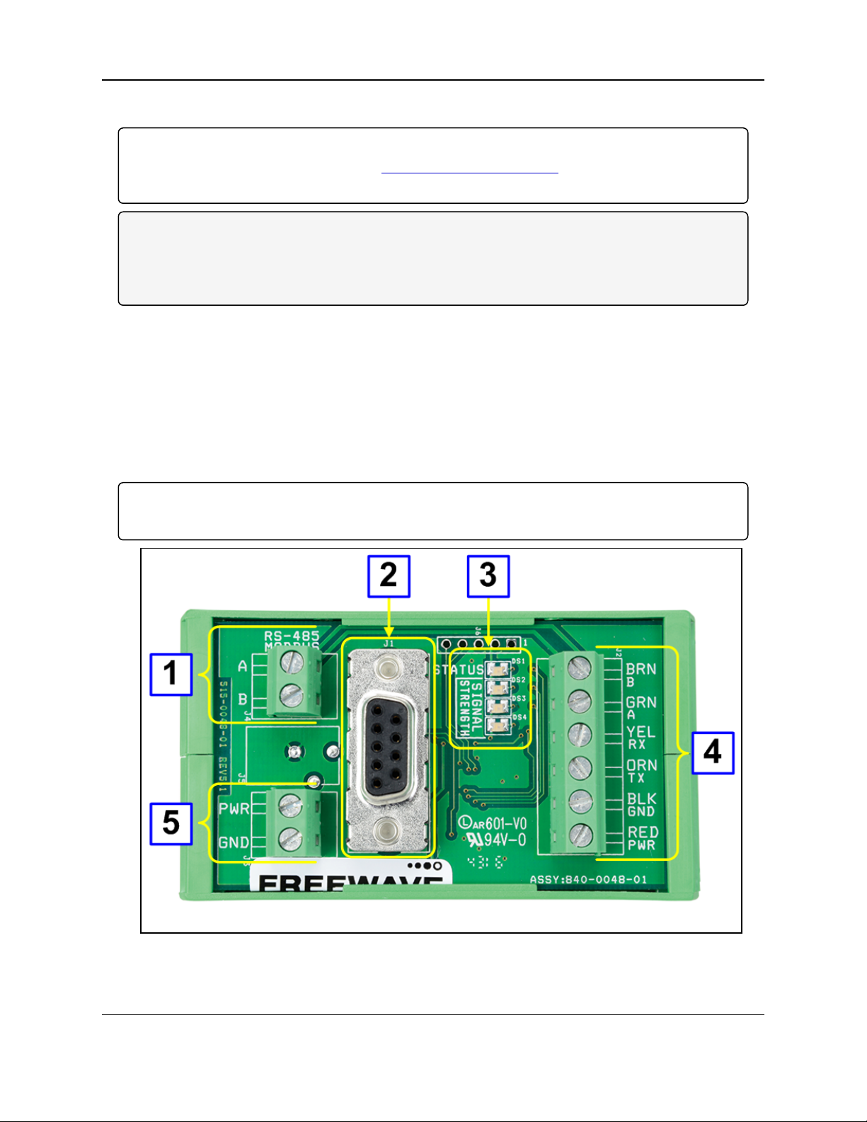
3.1.1. Connections - WC45i-BB
The WC45i-BB Smart Breakout Board (FreeWave Part #: WC45i-BB, Figure 1), is used to:
l Connect to the RS232 lines (#2)
l Configure the WC45i-GW-485 system (#4).
l Power the WC45i-GW-485 (#5).
Important!: The Signal Strength LEDs (#3) do NOT light at the Gateway as multiple Endpoints with
varying signal strength may be connected at one time.
Figure 1: WC45i-BB Smart Breakout Board used with the WC45i-GW-485
LUM0086AA Rev Mar-2018 Page 11 of 112 Copyright © 2018FreeWave
This document is the property of FreeWave Technologies, Inc. and contains proprietary information owned by
FreeWave. This document cannot be reproduced in whole or in part by any means without written permission from
FreeWave Technologies, Inc.
Page 12

WC45i-GW-485 Modbus Gateway: User & Reference Manual
WC45i-BB Smart Breakout Board Connections
Location # Title Description
1 RS485 Modbus
Block
Connect the Modbus master to the RS485 Modbus Block.
2 RS232 RS232
Config / Debug
connector
The RS232 Config / Debug connector is for the USB to Serial
DB9 programming cable (FreeWave Part # WC-USB-DB9).
3 Signal Strength
LEDs
See LEDs (on page 107) for detailed information.
4 l BRN-B
l GRN-A
l YEL-RX
l ORG-TX
l BLK-GND
l RED-PWR
l RS485B - 9600 Baud
l RS485A - 9600 Baud
l RS232Config / Debug connector RX - 9600 Baud
l RS232Config / Debug connector TX - 9600 Baud
l Ground
l Positive Power (+6 to +36VDC)
5 PWR
GND
Power Source from an external power supply of +6 to +36VDC.
External power ground.
LUM0086AA Rev Mar-2018 Page 12 of 112 Copyright © 2018FreeWave
This document is the property of FreeWave Technologies, Inc. and contains proprietary information owned by
FreeWave. This document cannot be reproduced in whole or in part by any means without written permission from
FreeWave Technologies, Inc.
Page 13
3. WC45i-GW-485 Connections
3.2. Power and Gateway Connections
Important!: Verify the items listed in Equipment (on page 9) are availablebefore starting this
procedure.
It is assumed that the readerand installer have completed the FreeWave WC45i-GW-485 installation
andsetup training to follow the procedures in this document.
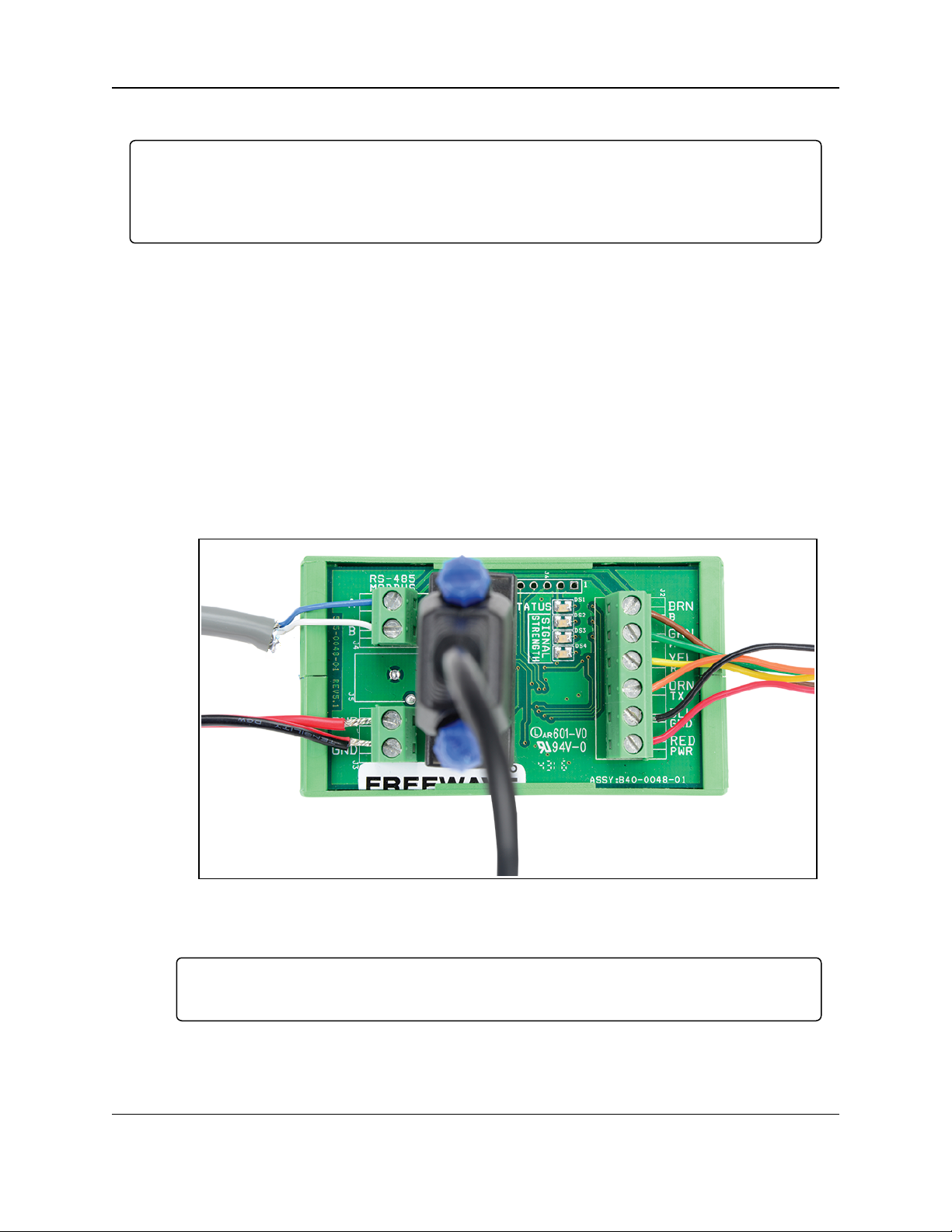
1. All wiring shouldbe neat and orderly.
2. On the WC45i-BB Smart Breakout Board:
a. Connect the configuration wires of the Gateway to their respectivecolor-designated
screw terminal connections.
b. Connect the Serial end of the WC-USB-DB9 cable to the RS232 Config / Debug
connector port and the USB connection to the computer.
c. Use the PWR screw terminal connection to connect the Power Source from an
external power supply of +6 to +36VDC.
d. Use the GND screw terminal connection to connect the External power ground.
e. Connect the Modbus master to the RS485 Modbus Block.
The WC45i-BB connections are similar to Figure 2:
Figure 2: WC45i-BB Connections
3. If this is the first time the WC45i-GW-485 is installed, wait for the drivers to install.
Important!: Depending on the computer and connection, the driverinstallationcan take 3-6
minutes.
4. Continue with:
l WC Toolkit Installation (on page 14)
l Configuration (on page 24)
LUM0086AA Rev Mar-2018 Page 13 of 112 Copyright © 2018FreeWave
This document is the property of FreeWave Technologies, Inc. and contains proprietary information owned by
FreeWave. This document cannot be reproduced in whole or in part by any means without written permission from
FreeWave Technologies, Inc.
Page 14
WC45i-GW-485 Modbus Gateway: User & Reference Manual
4. WC Toolkit Installation
Note: The images in this procedure are for Windows® 7 and/or Firefox®.
The dialog boxes and windows may appear differently on each computer.
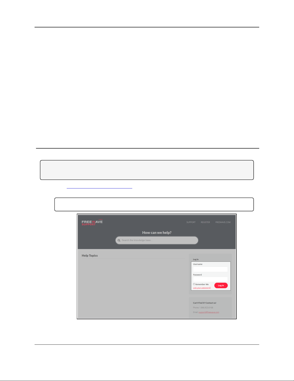
1. Click http://support.freewave.com/.
The FreeWave Support site opens.
Important!: Registration is required to use this website.
Figure 3: FreeWave Login window
2. Enter the User Name and Password.
LUM0086AA Rev Mar-2018 Page 14 of 112 Copyright © 2018FreeWave
This document is the property of FreeWave Technologies, Inc. and contains proprietary information owned by
FreeWave. This document cannot be reproduced in whole or in part by any means without written permission from
FreeWave Technologies, Inc.
Page 15
4. WC Toolkit Installation
3.
Click .
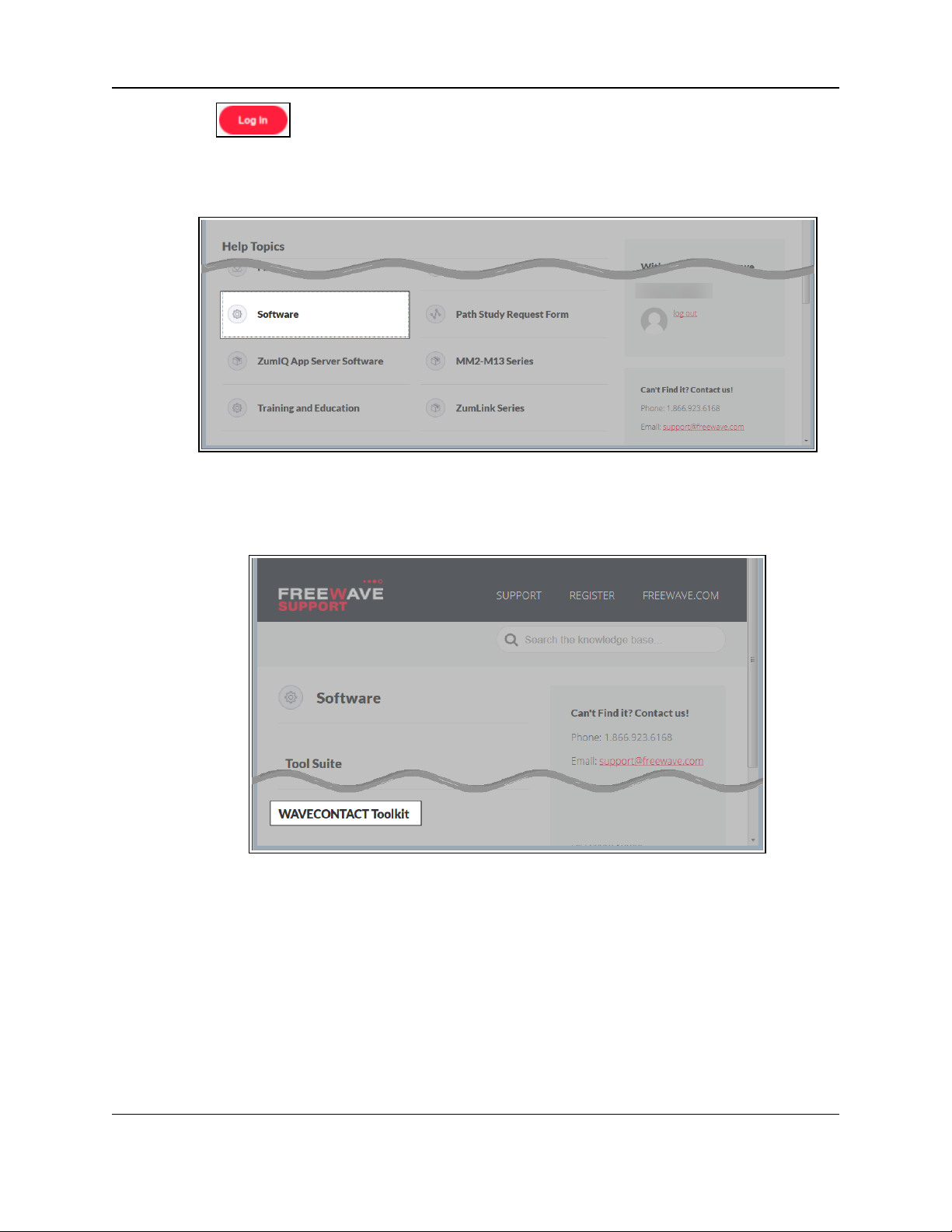
A successful Login message briefly appears.
The Help Topics window opens.
4. Click the Software link.
Figure 4: Help Topics window
The Software window opens.
5. Click the WAVECONTACT Toolkit link.
Figure 5: Software window
The available software appears in the window.
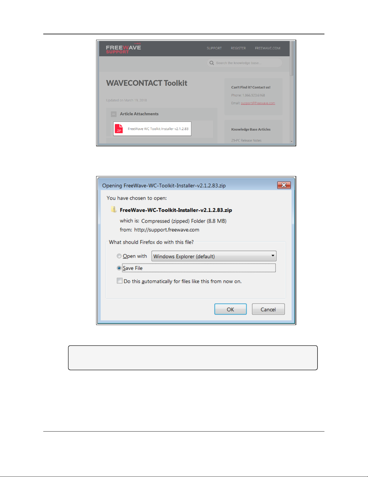
6. Select and click the attachment.
LUM0086AA Rev Mar-2018 Page 15 of 112 Copyright © 2018FreeWave
This document is the property of FreeWave Technologies, Inc. and contains proprietary information owned by
FreeWave. This document cannot be reproduced in whole or in part by any means without written permission from
FreeWave Technologies, Inc.
Page 16
WC45i-GW-485 Modbus Gateway: User & Reference Manual
Figure 6: WAVECONTACT Toolkit window
The Opening dialog box opens.
Figure 7: WC Toolkit Opening dialog box
Note: This procedure shows Firefox® dialog boxes.
Otherbrowsers will have different dialogboxes andprocedures.
7. Click OK.
The Enter name of file to save to dialog box opens.
LUM0086AA Rev Mar-2018 Page 16 of 112 Copyright © 2018FreeWave
This document is the property of FreeWave Technologies, Inc. and contains proprietary information owned by
FreeWave. This document cannot be reproduced in whole or in part by any means without written permission from
FreeWave Technologies, Inc.
Page 17
4. WC Toolkit Installation
Figure 8: Enter name of file to save to dialog box
8. Search for and select a location to save the .zip file to and click Save.
The Enter name of file to save to dialog box closes.
9. Open a Windows® Explorer window and find the location where the .zip file was saved.
10. Double-click the .zip file.
11. Extract the .exe file from the .zip file into a parent location.
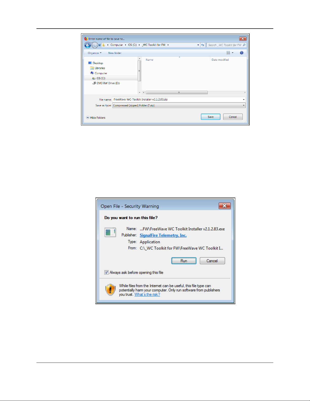
12. Double-click the .exe file to run the WC Toolkit installer.
The Open File - Security Warning dialog box opens.
Figure 9: Open File - Security Warning dialog box
13. Click Run.
The User Account Control dialog box opens.
LUM0086AA Rev Mar-2018 Page 17 of 112 Copyright © 2018FreeWave
This document is the property of FreeWave Technologies, Inc. and contains proprietary information owned by
FreeWave. This document cannot be reproduced in whole or in part by any means without written permission from
FreeWave Technologies, Inc.
Page 18
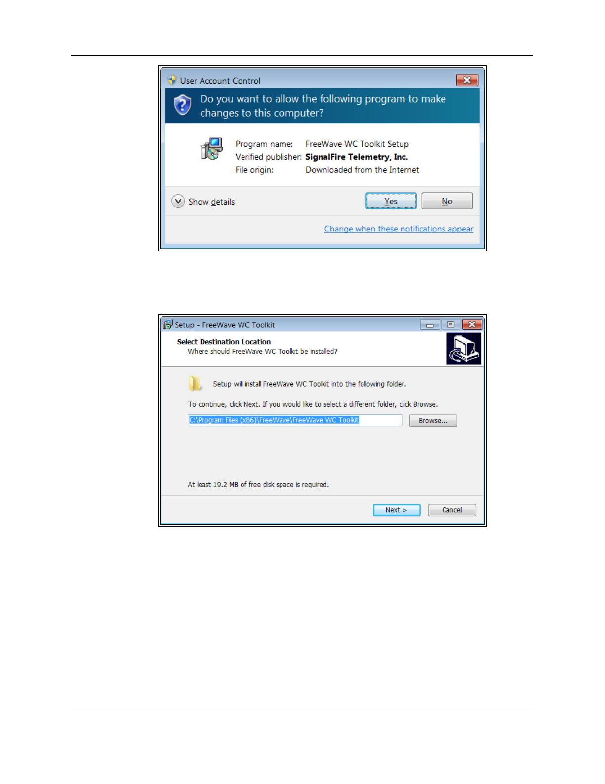
Figure 10: User Account Control dialog box
14. Click Yes.
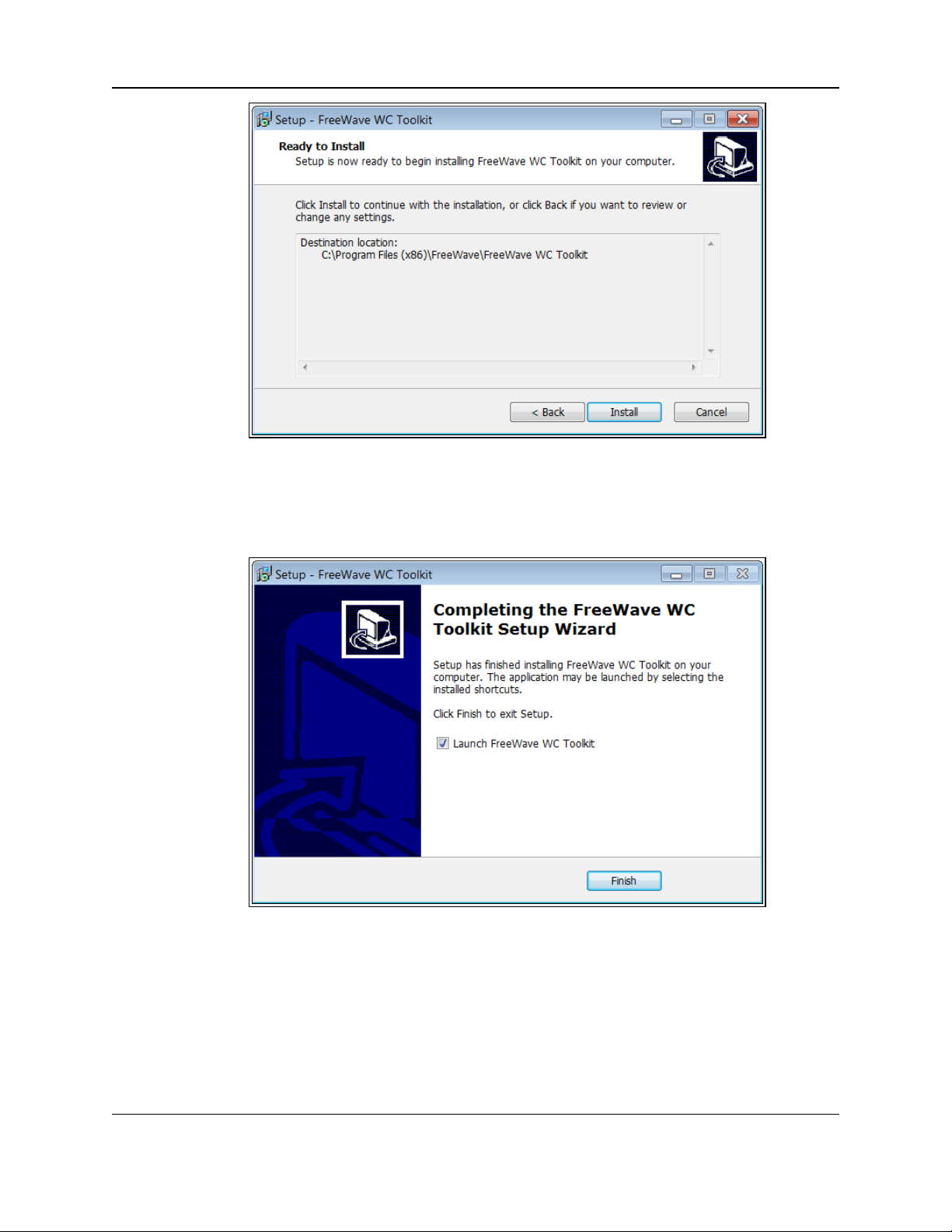
The WC Toolkit Setup Wizard starts.
WC45i-GW-485 Modbus Gateway: User & Reference Manual
Figure 11: WC Toolkit Setup Wizard - Select Destination Location window
15. Click Next to continue.
The Ready to Install window opens.
LUM0086AA Rev Mar-2018 Page 18 of 112 Copyright © 2018FreeWave
This document is the property of FreeWave Technologies, Inc. and contains proprietary information owned by
FreeWave. This document cannot be reproduced in whole or in part by any means without written permission from
FreeWave Technologies, Inc.
Page 19
4. WC Toolkit Installation
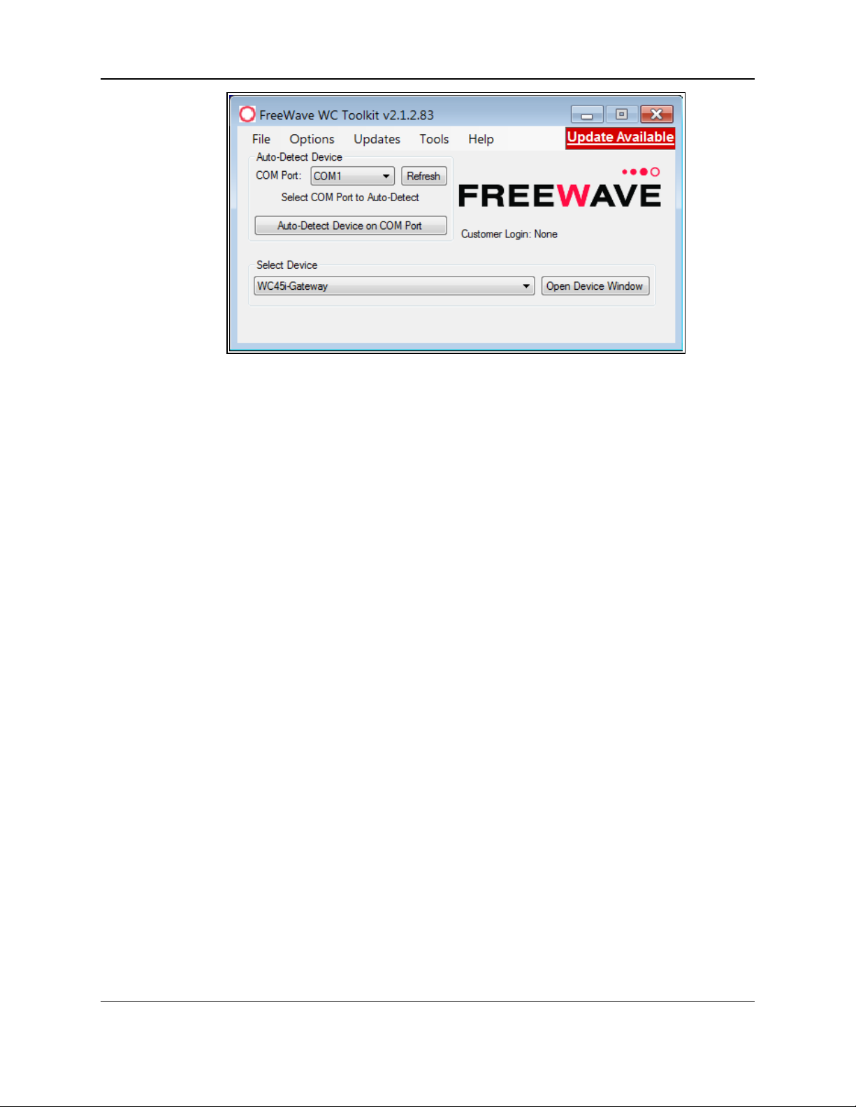
Figure 12: WC Toolkit Setup Wizard - Ready to Install window
16. Click Install.
The installprocess is very quick.
The Installation Complete window opens.
Figure 13: WC Toolkit Setup Wizard - Installation Complete window
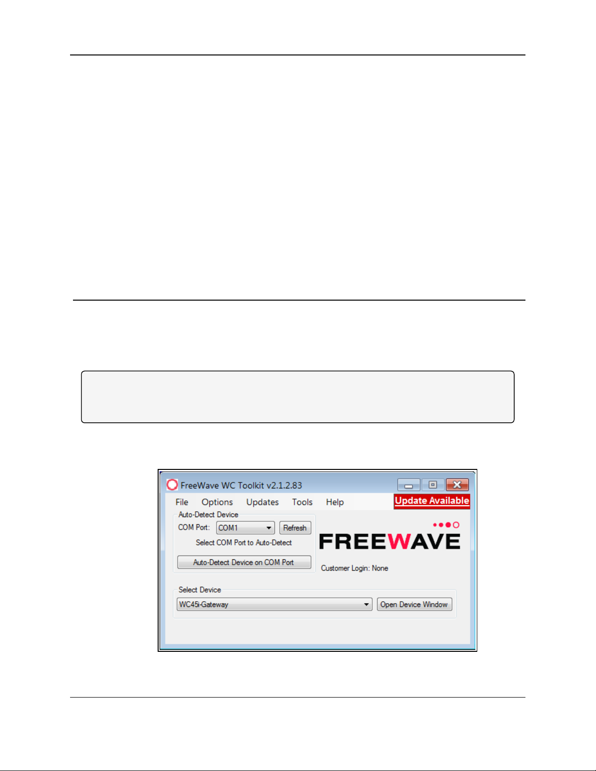
17. Click Finish to open WC Toolkit.
An Update message appears in the WC Toolkit window is an update is available.
LUM0086AA Rev Mar-2018 Page 19 of 112 Copyright © 2018FreeWave
This document is the property of FreeWave Technologies, Inc. and contains proprietary information owned by
FreeWave. This document cannot be reproduced in whole or in part by any means without written permission from
FreeWave Technologies, Inc.
Page 20
WC45i-GW-485 Modbus Gateway: User & Reference Manual
Figure 14: WC Toolkit - Update Available message
18. Continue with the WC Toolkit Update (on page 21) procedure.
LUM0086AA Rev Mar-2018 Page 20 of 112 Copyright © 2018FreeWave
This document is the property of FreeWave Technologies, Inc. and contains proprietary information owned by
FreeWave. This document cannot be reproduced in whole or in part by any means without written permission from
FreeWave Technologies, Inc.
Page 21
WC45i-GW-485 Modbus Gateway: User & Reference Manual
5. WC Toolkit Update
If the WAVECONTACT device is connected to the internet, WC Toolkit automaticallysearches for
an update for either the WC Toolkit itself or the connected device's firmware.
An Update Available message appears if an update is available.
Note: An Update Available message also appears in the Device Configuration window (onpage 57)
for any connected WAVECONTACT device when an update is availablefor that device.
The update procedure is the same for the device and WC Toolkit.
1. Open the WC Toolkit software.
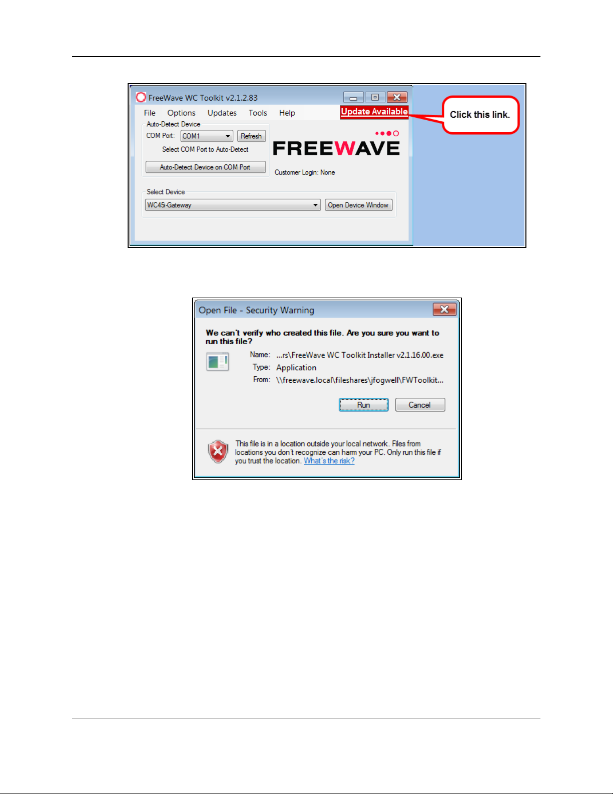
The Update Available message appears in the window. (Figure 15)
Figure 15: WC Toolkit - Update Available message
LUM0086AA Rev Mar-2018 Page 21 of 112 Copyright © 2018FreeWave
This document is the property of FreeWave Technologies, Inc. and contains proprietary information owned by
FreeWave. This document cannot be reproduced in whole or in part by any means without written permission from
FreeWave Technologies, Inc.
Page 22
5. WC Toolkit Update
2. Click the Update Available message link.
Figure 16: Click the Update Available message link
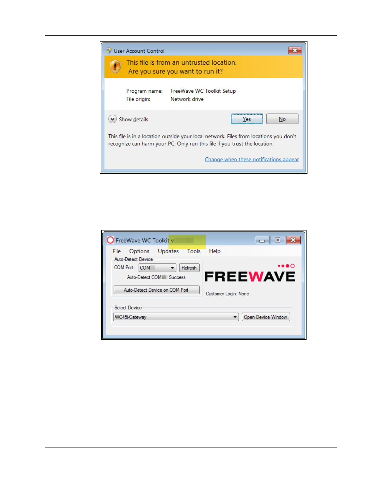
The Open File - Security Warning dialog box opens.
Figure 17: Open File - Security Warning dialog box
3. Click Run.
The User Account Control dialog box opens.
LUM0086AA Rev Mar-2018 Page 22 of 112 Copyright © 2018FreeWave
This document is the property of FreeWave Technologies, Inc. and contains proprietary information owned by
FreeWave. This document cannot be reproduced in whole or in part by any means without written permission from
FreeWave Technologies, Inc.
Page 23
WC45i-GW-485 Modbus Gateway: User & Reference Manual
Figure 18: User Account Control dialog box
4. Click Yes.
The WC Toolkit update processis very quick.
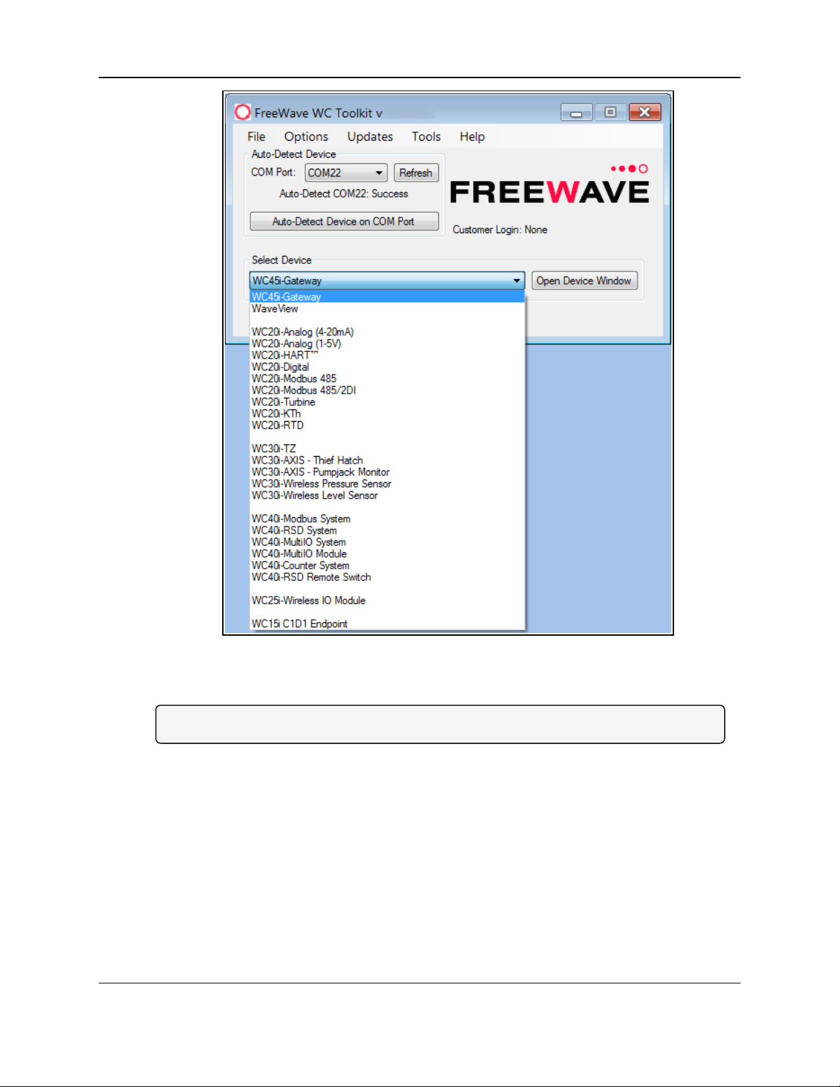
When the update is completed, WC Toolkit re-opens the Select Device window showing
the updated software version in the WC Toolkit window. (Figure 19)
Figure 19: Select Device window
5. Continue with Configuration of the WC45i-GW-485.
LUM0086AA Rev Mar-2018 Page 23 of 112 Copyright © 2018FreeWave
This document is the property of FreeWave Technologies, Inc. and contains proprietary information owned by
FreeWave. This document cannot be reproduced in whole or in part by any means without written permission from
FreeWave Technologies, Inc.
Page 24

WC45i-GW-485 Modbus Gateway: User & Reference Manual
6. Configuration
Note: The terms node and Endpoint are used interchangeably in this document.
FREEWAVE Recommends: Install and configurethe WC45i Gateway before any Endpoints to
ensure the Endpoints have connectivity after installation.
Important!: The WC45i-GW-485 Modbus Gateway is configured using the WC Toolkit.
Downloadthe WC Toolkit software from http://support.freewave.com/.
Registration is required to use this website.
Important!: The RS232 Config / Debug connector on the WC45i-GW MUST be used for WC
Toolkit access.
The Config / Debug port is accessed by a direct connection to the WC45i-GW-485 RS232 Config /
Debug connector port.
LUM0086AA Rev Mar-2018 Page 24 of 112 Copyright © 2018FreeWave
This document is the property of FreeWave Technologies, Inc. and contains proprietary information owned by
FreeWave. This document cannot be reproduced in whole or in part by any means without written permission from
FreeWave Technologies, Inc.
Page 25

6. Configuration
Procedure
Note: The screenshots are examples only.
The dialog boxes and windows appear differently on each computer.
1. Verify the WC Toolkit software is installed on the computer connected to the WC45i-GW-
485.
Note: See WC Toolkit Installation (on page 14) and WC Toolkit Update (on page 21).
2. Open the WC Toolkit software.
The Select Device window opens. (Figure 20)
Figure 20: Select Device window
3. Click the Refresh button to have WC Toolkit search for and list the available COM ports
reported by Windows and connected devices in the COM Port list box.
4. Click the COM Port list box arrow and select the COM port on the computer associated
with the connected WC45i-GW-485.
5. Click the Auto-Detect Device on COM Port button to have WC Toolkit connect the
device to the COM Port selected in the COM Port list box.
Note: Optional: Click the Select Device list box arrow and select the connected WC45i-
Gateway device.
Click the Open Device Window button to open the Device Configuration window (on page
57).
LUM0086AA Rev Mar-2018 Page 25 of 112 Copyright © 2018FreeWave
This document is the property of FreeWave Technologies, Inc. and contains proprietary information owned by
FreeWave. This document cannot be reproduced in whole or in part by any means without written permission from
FreeWave Technologies, Inc.
Page 26
WC45i-GW-485 Modbus Gateway: User & Reference Manual
Figure 21: Select Device list box
The Device Configuration window opens for the selected device.
Note: See Device Configuration window (on page 57) for detailed information.
LUM0086AA Rev Mar-2018 Page 26 of 112 Copyright © 2018FreeWave
This document is the property of FreeWave Technologies, Inc. and contains proprietary information owned by
FreeWave. This document cannot be reproduced in whole or in part by any means without written permission from
FreeWave Technologies, Inc.
Page 27
6. Configuration
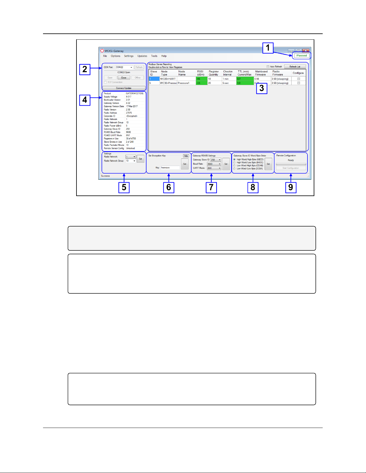
Figure 22: Device Configuration window: WC45i-Gateway
6. In the Settings area (#5), change these settings:
Note: The Network settings are used to create separate networks using multiple Gateways
(that are in close proximity to oneanother).
Important!: The Radio Network andRadio Network Group settings are selected by the
user but MUST MATCH the existing Gateway network for successful communication
between the Gateway and Endpoint.
See WAVECONTACT Network Frequencies (on page 95) for additional information.
a. Click the Radio Network list box arrow and select 0 (zero) to 7 for the assigned
number.
b. Click the Radio Network Group list box arrow and select 0 (zero) to 29 for the network
group assigned number.
c. Click the Set button to save the information.
7. In the Set Encryption Key area (#6), change these settings:
a. In the Key text box, enter the encryption key for the device using 6 to 16 characters.
b. Click the Set button to save the information.
Important!: A Key CANNOT contain spaces or angle brackets.
The Gateway andEndpoints only communicate if they areconfigured with the same Key.
When setting up a new network, use this same encryption Key on all the devices.
LUM0086AA Rev Mar-2018 Page 27 of 112 Copyright © 2018FreeWave
This document is the property of FreeWave Technologies, Inc. and contains proprietary information owned by
FreeWave. This document cannot be reproduced in whole or in part by any means without written permission from
FreeWave Technologies, Inc.
Page 28
WC45i-GW-485 Modbus Gateway: User & Reference Manual
Note: When the WC45i-GW-485 drops its network, it attempts to join networks using the
same encryption Key.
Caution: It is possible to hide the encryption Key so it cannot be read.
This is the most secure option, but if the Key is forgotten, there is no way to recover it.
The Key must be reset on every device on the network.
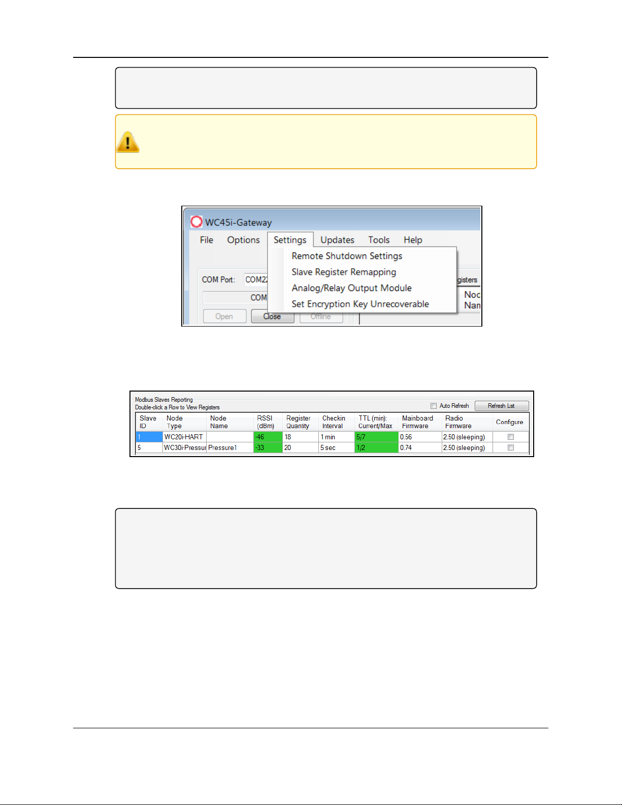
8. Optional: Click the Settings menu and select Set Encryption Key Unrecoverable to
permanently hide the key.
Figure 23: Settings menu > Set Encryption Key Unrecoverable
9. Click Refresh List button to update the Modbus Slaves Reporting table with all
connected remote Endpoints.
Figure 24: Modbus Slaves Reporting table
10. Configure the Endpoints attached to the WC45i-GW-485.
Note: Use the Configuration procedure in the User Manual for these WAVECONTACT
Endpoints:
WC15i Multi-Input C1D1 Endpoint, WC20i Endpoint,
WC30i Wireless Pressure Sensor, WC40i Modbus Endpoint,
WC40i-COUNT CounterEndpoint, or WC40i-MB-RSD Modbus Endpoint.
11. Optional: On the WC20i or WC45i-GW-485Endpoint, press the Check-in button to apply
power to the configured sensor, read the sensor values, and send the collected sensor data
to the Gateway.
12. Verify the Gateway is communicating with the Endpoints.
LUM0086AA Rev Mar-2018 Page 28 of 112 Copyright © 2018FreeWave
This document is the property of FreeWave Technologies, Inc. and contains proprietary information owned by
FreeWave. This document cannot be reproduced in whole or in part by any means without written permission from
FreeWave Technologies, Inc.
Page 29

6. Configuration
Note: A successful connection on the WAVECONTACT Endpoint is indicatedwith Green
blinking TX and ACT lights and a Red blinking light for RX.
If the connection is NOT successful, a Green blinking TX light appears for 10 seconds.
13. If applicable, continue with these other WC45i configuration procedures:
l Remote Endpoint Configuration (on page 40)
l Remote Shutdown (RSD) and Local Digital Output Control (on page 44)
l Slave Register Remapping (on page 48)
14. Close the WC Toolkit software.
15. Remove the WC-USB-DB9 USB to Serial DB9 programming cable from the computer and
the WC45i-BB.
16. As applicable, replace the Endpoint cover.
17. Mount the Gateway device.
LUM0086AA Rev Mar-2018 Page 29 of 112 Copyright © 2018FreeWave
This document is the property of FreeWave Technologies, Inc. and contains proprietary information owned by
FreeWave. This document cannot be reproduced in whole or in part by any means without written permission from
FreeWave Technologies, Inc.
Page 30
WC45i-GW-485 Modbus Gateway: User & Reference Manual
7. Gateway Event Log
The Gateway keeps an internal log of eventsthat are viewed in the Gateway Log window (on
page 73) of WC Toolkit.
The Gateway Log window is used to log eventssuch as reboots, remote Endpoints joining and/or
timing out, localRSD control events, remote configuration sessions, firmware updates, etc.
Procedure
Note: The terms node and Endpoint are used interchangeably in this document.
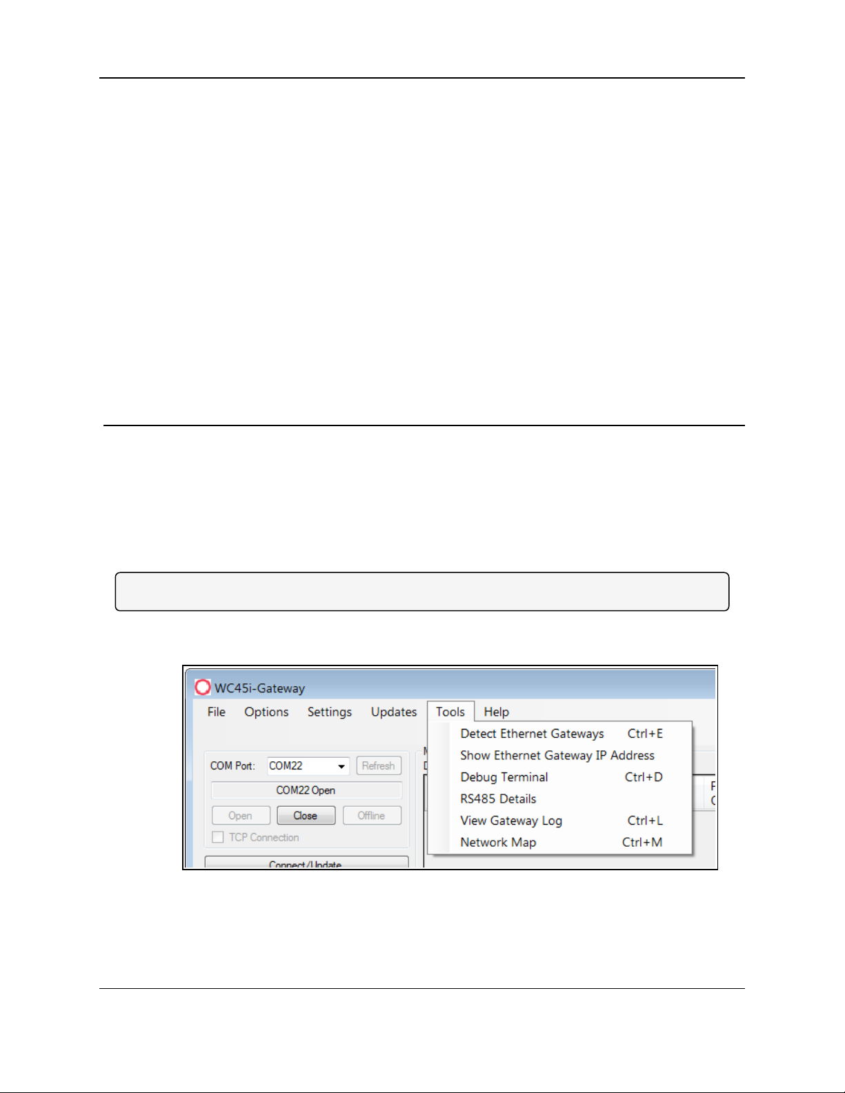
1. Open the Device Configuration window (on page 57).
2. On the Tools menu, click View Gateway Log.
Figure 25: Tools menu > View Gateway Log
The Gateway Log window opens.
The Gateway Log tab is active.
LUM0086AA Rev Mar-2018 Page 30 of 112 Copyright © 2018FreeWave
This document is the property of FreeWave Technologies, Inc. and contains proprietary information owned by
FreeWave. This document cannot be reproduced in whole or in part by any means without written permission from
FreeWave Technologies, Inc.
Page 31

7. Gateway Event Log
Figure 26: Gateway Log window - Gateway Log tab
3. Complete any of these options:
l Click the Refresh or Refresh List button to update the informationin the table.
l Click the Log Entries list box arrow and select how many log entries to view on the
Gateway Log tab.
l Click the Load Log from File button to open the Microsoft® Open dialog box with the
default location where the .csv file of the log information is saved.
l Click the Save Log to File button to open the Microsoft® Save As dialog box with the
default location to save the .csv file of the log information in.
4. Optional: Click the Log Statistics tab to view statistics about the log events.
Figure 27: Gateway Log window - Log Statistics tab
5. Optional: Click the Refresh or Refresh List button to update the information in the table.
6. Optional: Click the Save Report to File button to open the Microsoft® Save As dialog box
with the default location to save the CSV version of the log file in.
7. Close the Gateway Log window.
LUM0086AA Rev Mar-2018 Page 31 of 112 Copyright © 2018FreeWave
This document is the property of FreeWave Technologies, Inc. and contains proprietary information owned by
FreeWave. This document cannot be reproduced in whole or in part by any means without written permission from
FreeWave Technologies, Inc.
Page 32

WC45i-GW-485 Modbus Gateway: User & Reference Manual
8. Firmware Updates
Firmware updates for both the Gateway and the built-in radio are completedover:
l the RS232 Config / Debug connector port usingWC Toolkit.
l a remote TCP connection if a WC45i-GW-P Ethernet Gateway is used.
Note: These procedures are for both the WC45i-GW-485 and WC45i-GW-DIN devices.
l Gateway Firmware Update (on page 33)
l Radio Firmware Update (on page 35)
l Rescue Gateway (ARM) Bootload (on page 37)
LUM0086AA Rev Mar-2018 Page 32 of 112 Copyright © 2018FreeWave
This document is the property of FreeWave Technologies, Inc. and contains proprietary information owned by
FreeWave. This document cannot be reproduced in whole or in part by any means without written permission from
FreeWave Technologies, Inc.
Page 33

8. Firmware Updates
8.1. Gateway Firmware Update
1. Verify the WC Toolkit software is installed on the computer connected to the WC45i-GW-
485.
Note: See WC Toolkit Installation (on page 14) and WC Toolkit Update (on page 21).
2. Open the WC Toolkit software.
The Select Device window opens. (Figure 28)
Figure 28: Select Device window
3. Click the Refresh button to have WC Toolkit search for and list the available COM ports
reported by Windows and connected devices in the COM Port list box.
4. Click the COM Port list box arrow and select the COM port on the computer associated
with the connected WC45i-GW-485.
5. Click the Auto-Detect Device on COM Port button to have WC Toolkit connect the
device to the COM Port selected in the COM Port list box.
The Device Configuration window opens for the selected device.
6. On the Update menu, click Update Gateway Firmware.
Figure 29: Updates menu > Update Gateway Firmware
The Firmware Updates window opens.
Note: See Firmware Updates window (on page 71) for detailedinformation.
LUM0086AA Rev Mar-2018 Page 33 of 112 Copyright © 2018FreeWave
This document is the property of FreeWave Technologies, Inc. and contains proprietary information owned by
FreeWave. This document cannot be reproduced in whole or in part by any means without written permission from
FreeWave Technologies, Inc.
Page 34

WC45i-GW-485 Modbus Gateway: User & Reference Manual
Figure 30: Firmware Updates window
Note: By default, the latest firmware file is selected from the update server.
When the Update Gateway Firmware menu is selected, the WC45i-Gateway searches for
the most recent modbusGW file to update.
7. Click the Start Transfer button to load the file to the device.
8. Wait while the Firmware Updates window progressbar shows the file transfer.
Figure 31: Progress bar of firmware update
A message appears when the firmware update is successful.
Figure 32: Successful firmware update message
9. Click OK to close the message.
LUM0086AA Rev Mar-2018 Page 34 of 112 Copyright © 2018FreeWave
This document is the property of FreeWave Technologies, Inc. and contains proprietary information owned by
FreeWave. This document cannot be reproduced in whole or in part by any means without written permission from
FreeWave Technologies, Inc.
Page 35

8. Firmware Updates
8.2. Radio Firmware Update
1. Verify the WC Toolkit software is installed on the computer connected to the WC45i-GW-
485.
Note: See WC Toolkit Installation (on page 14) and WC Toolkit Update (on page 21).
2. Open the WC Toolkit software.
The Select Device window opens. (Figure 28)
Figure 33: Select Device window
3. Click the Refresh button to have WC Toolkit search for and list the available COM ports
reported by Windows and connected devices in the COM Port list box.
4. Click the COM Port list box arrow and select the COM port on the computer associated
with the connected WC45i-GW-485.
5. Click the Auto-Detect Device on COM Port button to have WC Toolkit connect the
device to the COM Port selected in the COM Port list box.
The Device Configuration window opens for the selected device.
6. On the Update menu, click Update Gateway Firmware.
Figure 34: Updates menu > Update Radio Firmware
The Firmware Updates window opens.
Note: See Firmware Updates window (on page 71) for detailedinformation.
LUM0086AA Rev Mar-2018 Page 35 of 112 Copyright © 2018FreeWave
This document is the property of FreeWave Technologies, Inc. and contains proprietary information owned by
FreeWave. This document cannot be reproduced in whole or in part by any means without written permission from
FreeWave Technologies, Inc.
Page 36

WC45i-GW-485 Modbus Gateway: User & Reference Manual
Figure 35: Firmware Updates window
Note: By default, the latest firmware file is selected from the update server.
When the Update Radio Firmware menu is selected, the WC45i-Gateway searches for the
most recent appNode file to update.
7. Click the Start Transfer button to load the file to the device.
8. Wait while the Firmware Updates window progressbar shows the file transfer.
Figure 36: Progress bar of firmware update
A message appears when the firmware update is successful.
Figure 37: Successful firmware update message
9. Click OK to close the message.
LUM0086AA Rev Mar-2018 Page 36 of 112 Copyright © 2018FreeWave
This document is the property of FreeWave Technologies, Inc. and contains proprietary information owned by
FreeWave. This document cannot be reproduced in whole or in part by any means without written permission from
FreeWave Technologies, Inc.
Page 37

8. Firmware Updates
8.3. Rescue Gateway (ARM) Bootload
Possible causesto run a Rescue Bootload:
l Power failure.
l Communications failure during firmware update process.
l The base LED is solidon and/or the WC Toolkit is unableto communicatewith the
Gateway.
Procedure
1. Remove the DC power from the Gateway.
2. Verify the WC Toolkit software is installed on the computer connected to the WC45i-GW-
485.
Note: Download the WC Toolkit softwarefrom http://support.freewave.com/.
3. Open the WC Toolkit software.
The Select Device window opens. (Figure 28)
Figure 38: Select Device window
4. Click the Refresh button to have WC Toolkit search for and list the available COM ports
reported by Windows and connected devices in the COM Port list box.
5. Click the COM Port list box arrow and select the COM port on the computer associated
with the connected WC45i-GW-485.
6. Click the Auto-Detect Device on COM Port button to have WC Toolkit connect the
device to the COM Port selected in the COM Port list box.
The Device Configuration window opens for the selected device.
7. On the Update menu, click Update Gateway Firmware.
LUM0086AA Rev Mar-2018 Page 37 of 112 Copyright © 2018FreeWave
This document is the property of FreeWave Technologies, Inc. and contains proprietary information owned by
FreeWave. This document cannot be reproduced in whole or in part by any means without written permission from
FreeWave Technologies, Inc.
Page 38

WC45i-GW-485 Modbus Gateway: User & Reference Manual
Figure 39: Updates menu > Update Gateway Firmware
The Firmware Updates window opens.
Note: See Firmware Updates window (on page 71) for detailedinformation.
Figure 40: Firmware Updates window
Note: By default, the latest firmware file is selected from the update server.
When the Update Gateway Firmware menu is selected, the WC45i-Gateway searches for
the most recent modbusGW file to update.
8. Click the Start Transfer button to load the file to the device.
Wait while the Firmware Updates window progress bar shows the file transfer.
Figure 41: Progress bar of firmware update
A message appears when the firmware update is successful.
LUM0086AA Rev Mar-2018 Page 38 of 112 Copyright © 2018FreeWave
This document is the property of FreeWave Technologies, Inc. and contains proprietary information owned by
FreeWave. This document cannot be reproduced in whole or in part by any means without written permission from
FreeWave Technologies, Inc.
Page 39

8. Firmware Updates
Figure 42: Successful firmware update message
9. Re-connect the DC power to the Gateway.
The firmware update process starts.
Note: If the firmware update does NOT start, remove power for at least 10 seconds and re-try.
LUM0086AA Rev Mar-2018 Page 39 of 112 Copyright © 2018FreeWave
This document is the property of FreeWave Technologies, Inc. and contains proprietary information owned by
FreeWave. This document cannot be reproduced in whole or in part by any means without written permission from
FreeWave Technologies, Inc.
Page 40

WC45i-GW-485 Modbus Gateway: User & Reference Manual
9. Remote Endpoint Configuration
The WC45i-GW-485 Modbus Gateway allows configuration changes to be made to any of the
connected WAVECONTACT remote Endpoints wirelessly.
l The WC45i-GW-485 requiresan initialconfiguration using the Config / Debug connector.
l The Config / Debug port is accessed by a direct connection to the WC45i-GW-485
RS232 Config / Debug connector port.
Note: This procedure assumes WC Toolkit has been installed.
Downloadthe WC Toolkit software from http://support.freewave.com/.
Registration is required to use this website.
Procedure
Note: The terms node and Endpoint are used interchangeably in this document.
1. Open the Device Configuration window (on page 57).
2. In the Configure column, select the check-box next to the Endpoint to configure.
LUM0086AA Rev Mar-2018 Page 40 of 112 Copyright © 2018FreeWave
This document is the property of FreeWave Technologies, Inc. and contains proprietary information owned by
FreeWave. This document cannot be reproduced in whole or in part by any means without written permission from
FreeWave Technologies, Inc.
Page 41

9. Remote Endpoint Configuration
Figure 43: Detail of Endpoint in Modbus Slaves Reporting Table
3. Click the Start Configuration button to activate a Remote Configuration session.
l If the Endpoint has a Non-Sleeping radio, the Remote Configuration session is
ready immediately.
l If it is a Sleeping device, wait for the Endpoint to either check-inor send a beacon so it
can be commanded into Configuration mode.
l A WC20i Endpoint sends a beaconevery 2½ minutes.
l All other Sleeping Endpoints send a beacon every 5½ minutes.
l When the device has entered a Remote Configuration session, a message indicating
the Slave is Ready appears.
LUM0086AA Rev Mar-2018 Page 41 of 112 Copyright © 2018FreeWave
This document is the property of FreeWave Technologies, Inc. and contains proprietary information owned by
FreeWave. This document cannot be reproduced in whole or in part by any means without written permission from
FreeWave Technologies, Inc.
Page 42

WC45i-GW-485 Modbus Gateway: User & Reference Manual
Figure 44: Remote Configuration area - Slave is Ready
4. Click the Configure button to open the Edit Configurationwindow (on page 64).
Important!: The Remote Configuration session automatically times out after 10 minutes of
inactivity and the Endpoint will resume normal operation.
Note: The Edit Configuration window is uniquefor the selected Endpoint device.
Figure 45 shows the Edit Configuration window for a WC20i-HART Endpoint.
LUM0086AA Rev Mar-2018 Page 42 of 112 Copyright © 2018FreeWave
This document is the property of FreeWave Technologies, Inc. and contains proprietary information owned by
FreeWave. This document cannot be reproduced in whole or in part by any means without written permission from
FreeWave Technologies, Inc.
Page 43

9. Remote Endpoint Configuration
Figure 45: Edit Configuration window - WC20i-HART
5. Make any necessary changes in the active areas of the window and click the corresponding
Set button to save the changes.
6. When finished changing the configuration, closethe Edit Configuration window and
return to the Device Configuration window.
7. Click the End button to stop the Remote Configuration session.
Note: The Remote Configuration session automatically times-out after 10 minutes of
inactivity.
8. Optional: On the WC20i or WC45i-GW-485Endpoint, press the Check-in button to apply
power to the configured sensor, read the sensor values, and send the collected sensor data
to the Gateway.
9. Verify the Gateway is communicating with the Endpoints.
Note: A successful connection on the WAVECONTACT Endpoint is indicatedwith Green
blinking TX and ACT lights and a Red blinking light for RX.
If the connection is NOT successful, a Green blinking TX light appears for 10 seconds.
10. Close the WC Toolkit software.
11. Remove the WC-USB-DB9 USB to Serial DB9 programming cable from the computer and
the WC45i-BB.
12. As applicable, replace the Endpoint cover.
13. Mount the Gateway device.
LUM0086AA Rev Mar-2018 Page 43 of 112 Copyright © 2018FreeWave
This document is the property of FreeWave Technologies, Inc. and contains proprietary information owned by
FreeWave. This document cannot be reproduced in whole or in part by any means without written permission from
FreeWave Technologies, Inc.
Page 44

WC45i-GW-485 Modbus Gateway: User & Reference Manual
10. Remote Shutdown (RSD) and Local Digital Output Control
The WC45i-GW-485 Modbus Gateway supportsInternalLogic Control capabilitywhich enables
the Gateway to control output relays on the WC40i-MB-RSD Modbus Endpoint or WC40iCOUNT.
Note: The WC40i-MB-RSD Modbus Endpoint bundle includes the WC40i-MB and the WC40i-RSD
products.
l The WC45i-GW-485 receives data from multiple remote Endpoints.
l The data is used from those remote Endpoints to set the relay output on one or more
remote WC40i-MB-RSD or WC40i-COUNT.
l An example of the topologyis shown in Figure 46.
Note: See Connections (on page 11) for port locations.
Use the Remote Shutdown Configuration (on page 46) procedure to control the output relays.
LUM0086AA Rev Mar-2018 Page 44 of 112 Copyright © 2018FreeWave
This document is the property of FreeWave Technologies, Inc. and contains proprietary information owned by
FreeWave. This document cannot be reproduced in whole or in part by any means without written permission from
FreeWave Technologies, Inc.
Page 45

10. Remote Shutdown (RSD) and Local Digital Output Control
10.1. Example: WC45i-GW-485 Modbus Gateway Topology
Figure 46: Example: WC45i-GW-485 Modbus Gateway Topology
LUM0086AA Rev Mar-2018 Page 45 of 112 Copyright © 2018FreeWave
This document is the property of FreeWave Technologies, Inc. and contains proprietary information owned by
FreeWave. This document cannot be reproduced in whole or in part by any means without written permission from
FreeWave Technologies, Inc.
Page 46

WC45i-GW-485 Modbus Gateway: User & Reference Manual
10.2. Remote Shutdown Configuration
Note: The terms node and Endpoint are used interchangeably in this document.
1. Open the Device Configuration window (on page 57).
2. On the Settings menu, click Remote Shutdown Settings.
Figure 47: Settings menu > Remote Shutdown Settings
The Remote Shutdown Settings window (on page 84) opens.
Figure 48: Remote Shutdown Settings window
3. As appropriate, completethese sectionsof the window:
a. Source Node (Endpoint) area (on page 86).
b. Relay Control LogicSection (on page 88).
c. Destination Counter / RSD StickSection (on page 90).
4. Click the Write Remote Shutdown Settings to Gateway button to store the settingsin
the WC45i-Gateway.
5. Optional: Click the Failsafe Enabled check box to require ALL rules to have valid data for
the relay to be energized.
LUM0086AA Rev Mar-2018 Page 46 of 112 Copyright © 2018FreeWave
This document is the property of FreeWave Technologies, Inc. and contains proprietary information owned by
FreeWave. This document cannot be reproduced in whole or in part by any means without written permission from
FreeWave Technologies, Inc.
Page 47

10. Remote Shutdown (RSD) and Local Digital Output Control
Important!: If one or moreof the Endpoints time-out or does not exist, the relay is de-
energized.
If this option is NOT selected, then an Endpoint that is not installedor fails to check in is
ignored and the relay is energized using logic only from the units that are active.
6. Optional: Click the Latch De-Energized check box so the rules may only de-energize the
relay.
Note: For the relay to be energized again, a Modbus write from a PLC to the Gateway for the
destination WC40i-MB-RSD or WC40i-COUNT relay must occur.
This is useful if manual intervention is required before the relay is energized after an event.
In 10, a Modbus coil write to Slave ID 5 relay channel 1 (which is register 1) is required to
energize the relay.
LUM0086AA Rev Mar-2018 Page 47 of 112 Copyright © 2018FreeWave
This document is the property of FreeWave Technologies, Inc. and contains proprietary information owned by
FreeWave. This document cannot be reproduced in whole or in part by any means without written permission from
FreeWave Technologies, Inc.
Page 48

WC45i-GW-485 Modbus Gateway: User & Reference Manual
11. Slave Register Remapping
The Gateway allows any of the remote register data to be remappedto a single block of registers
available at the Gateway’s Slave ID.
Note: The default is 247.
l This is useful for collecting a subset of register data from multipleEndpoints and making it
readable in a single blockof registers.
l A maximum of 750 registerscan be remapped to the Gateway’s Slave ID starting at register
5000.
Procedure
Note: The terms node and Endpoint are used interchangeably in this document.
1. Open the Device Configuration window (on page 57).
2. On the Settings menu, click Slave Register Remapping.
Figure 49: Settings menu > Slave Register Remapping
LUM0086AA Rev Mar-2018 Page 48 of 112 Copyright © 2018FreeWave
This document is the property of FreeWave Technologies, Inc. and contains proprietary information owned by
FreeWave. This document cannot be reproduced in whole or in part by any means without written permission from
FreeWave Technologies, Inc.
Page 49

11. Slave Register Remapping
The Slave Register Remapping window (on page 91) opens.
Figure 50: Slave Register Remapping window
3. In the Slave ID column / text box, enter the remote source Endpoint ModbusSlaveID.
Important!: Verify there are no duplicate Slave IDs in a given network.
The Gateway only caches oneset of data for each Slave ID.
A duplicate is overwritten.
4. In the Register Address column text box, enter the register addressto map to each
Gateway register.
Note: The Node Name, Data Type, Register Value, and Description columns are
automatically filled in by the Gateway once the mapping is written to the Gateway.
5. Click the Write Mapping to Gateway button to remap the registers.
Figure 51 shows an exampleof a the Slave Register Remapping window.
l Slave ID 1 is a WC20i-AN Analog Endpoint mapped to have sensor current, RSSI
and battery voltageavailable at Gateway registers 5000 through 5002.
l Slave ID 5 is NOT reporting data to the Gateway so its registers are failing high.
Figure 51: Example of the Slave Register Remapping window
LUM0086AA Rev Mar-2018 Page 49 of 112 Copyright © 2018FreeWave
This document is the property of FreeWave Technologies, Inc. and contains proprietary information owned by
FreeWave. This document cannot be reproduced in whole or in part by any means without written permission from
FreeWave Technologies, Inc.
Page 50

WC45i-GW-485 Modbus Gateway: User & Reference Manual
Important!: If the Gateway does NOT have data for a remapped value, it will respond with
0xFFFF, or 0x0000 for the register request.
Use the Fail Mode settings to configure this globally.
Note: 0xFFFF = 65535, 0x0000 = 0.
LUM0086AA Rev Mar-2018 Page 50 of 112 Copyright © 2018FreeWave
This document is the property of FreeWave Technologies, Inc. and contains proprietary information owned by
FreeWave. This document cannot be reproduced in whole or in part by any means without written permission from
FreeWave Technologies, Inc.
Page 51

WC45i-GW-485 Modbus Gateway: User & Reference Manual
12. Modbus Gateway Register Map
Important!: By default, the WAVECONTACT Modbus Gateway is assigned Modbus Slave ID
number247.
l Onlythe Gateway status / configuration registers are read at this address.
l All remote Endpoint registers are read from the Slave ID and Register Address of the
remote Endpoint, unless the SlaveRegister Remapping (on page 48) procedure is used.
l Registers include:
l Boolean Registers(on page 52)
l Read / Write Registers (on page 52)
l Read-only Registers(on page 53)
LUM0086AA Rev Mar-2018 Page 51 of 112 Copyright © 2018FreeWave
This document is the property of FreeWave Technologies, Inc. and contains proprietary information owned by
FreeWave. This document cannot be reproduced in whole or in part by any means without written permission from
FreeWave Technologies, Inc.
Page 52

12. Modbus Gateway Register Map
Boolean Registers
Register Number
Register Address
(Offset)
Description
00001 0000 Resets the Gateway and radio.
00002 0001 Resets the radio leaving the Gateway on.
00003 0002 Resets all counters to zero.
Note: See Modbus Gateway Register Map
(onpage 51) 2026-2031.
Read / Write Registers
Register Number
Register Address
(Offset)
Description
41001 1000 Resets the Gateway and radio
41002 1001 Resets the radio leaving the Gateway on
41003 1002 Resets all GW status counters to zero.
Note: See Modbus Gateway Register Map
(onpage 51) 2026-2031.
12.1. Boolean Registers
l These are 1-bit coil registers.
l They can only be written to Modbus opcode 0x05 (Write Single Coil).
l Writing 0x0000 to a coil has NO effect.
l To perform these resets, write a 0xFF00 to the respective coil:
12.2. Read / Write Registers
l These are 16-bit read/write registers.
l They can be written to by Modbus opcode 0x06 or 0x10 (Write Single and Multiple
Registers, respectively).
l They can be read with Modbusopcode 0x03 or 0x04 (Read Discrete Input and Holding
Registers, respectively).
l The first three registersare identical to the previous three write coils and behave similarly.
l They will be read as 0x0000 and can be triggered by writing 0xFF00 to them.
l The remaining must be written with 16-bit values in the range specified in the Read / Write
Registers (on page 52) table:
FreeWave. This document cannot be reproduced in whole or in part by any means without written permission from
LUM0086AA Rev Mar-2018 Page 52 of 112 Copyright © 2018FreeWave
This document is the property of FreeWave Technologies, Inc. and contains proprietary information owned by
FreeWave Technologies, Inc.
Page 53

12.3. Read-only Registers
Read-only Registers
Register Number
Register Address
(Offset)
Description
42001 2000 Upper 16 bits of SFTS GW Endpoint address (the radio
ID).
42002 2001 Lower 16 bits of SFTS GW Endpoint address (the radio
ID).
42003 2002 Upper 16 bits of RadioFirmware version number.
42004 2003 Lower 16 bits of RadioFirmware version number.
42005 2004 Upper 16 bits of Gateway firmwareversionnumber.
42006 2005 Lower 16 bits of Gateway firmwareversionnumber.
42007 2006 Number of slave Endpoints that data is cached for this
Gateway.
42008 2007 Total number of registers allocated to slave devices.
42009 2008 Total number of freeregisters available for slave
devices.
42010 2009 Bitmask for active slave IDs 15-0 (LSB is 0).
42011 2010 Bitmask for active slave IDs 31-16 (LSB is 16).
42012 2011 Bitmask for active slave IDs 47-32 (LSB is 32).
42013 2012 Bitmask for active slave IDs 63-48 (LSB is 48).
42014 2013 Bitmask for active slave IDs 79-64 (LSB is 64).
42015 2014 Bitmask for active slave IDs 95-80 (LSB is 80).
42016 2015 Bitmask for active slave IDs 111-96 (LSB is 96).
42017 2016 Bitmask for active slave IDs 127-112(LSB is 112).
42018 2017 Bitmask for active slave IDs 143-128(LSB is 128).
42019 2018 Bitmask for active slave IDs 159-144(LSB is 144).
42020 2019 Bitmask for active slave IDs 175-160(LSB is 160).
42021 2020 Bitmask for active slave IDs 191-176(LSB is 176).
42022 2021 Bitmask for active slave IDs 207-192(LSB is 192).
42023 2022 Bitmask for active slave IDs 223-208(LSB is 208).
Note: If the Gateway has a large total number of registers approaching 4700, register 2008 should be
monitored to ensure that freeregisters are available before adding a new Endpoint.
WC45i-GW-485 Modbus Gateway: User & Reference Manual
l These are 16-bit Read-onlyregisters.
l They can be read with Modbusopcode 0x03 or 0x04 (Read Discrete Input and Holding
Registers, respectively).
LUM0086AA Rev Mar-2018 Page 53 of 112 Copyright © 2018FreeWave
This document is the property of FreeWave Technologies, Inc. and contains proprietary information owned by
FreeWave. This document cannot be reproduced in whole or in part by any means without written permission from
FreeWave Technologies, Inc.
Page 54

12. Modbus Gateway Register Map
Read-only Registers
Register Number
Register Address
(Offset)
Description
42024 2023 Bitmask for active slave IDs 239-224(LSB is 224).
42025 2024 Bitmask for active slave IDs 255-240(LSB is 240).
42026 2025 Gateway power supply voltage in mV.
42027 2026 Radio packets received count.
42028 2027 Radio packets sent count.
42029 2028 RS-485 messages received count.
42030 2029 RS-485 messages sent count .
42031 2030 Total Modbus errors from master andslaves.
42032 2031 Modbus exceptions from slave Endpoints.
42033 2032 Radio packets received / transmitted per minute.
FREEWAVE Recommends: Less than60
42034 2033 Radio packets per minute alert.
l 0 (zero) if packets/min <= 60.
l 1 if packets/min > 60.
42101 2100 Address test register.
Note: This register always returns 2100.
42102 2101 Address test register.
Note: This register always returns 2101.
42103 2102 Address test register.
Note: This register always returns 2102.
43001 3000 Writes the radio address of an Endpoint to this register
to cause that WC45i-GW-485 to perform a scan for
attached Modbus sensors.
43004 3003 Writes Modbus ID for a Modbus Client Endpoint to this
register to cause that remote Endpoint to perform a scan
for attached Modbus sensors.
44002 4001 Status of Slave ID 1.
Note: This register returns 1 if Slave is present
and0 (zero) if Slave is not present.
LUM0086AA Rev Mar-2018 Page 54 of 112 Copyright © 2018FreeWave
This document is the property of FreeWave Technologies, Inc. and contains proprietary information owned by
FreeWave. This document cannot be reproduced in whole or in part by any means without written permission from
FreeWave Technologies, Inc.
Page 55

WC45i-GW-485 Modbus Gateway: User & Reference Manual
Read-only Registers
Register Number
Register Address
(Offset)
Description
44003 4002 Status of Slave ID 2.
Note: This register returns 1 if Slave is present
and0 (zero) if Slave is not present.
44241 4240 Status of Slave ID 240.
Note: This register returns 1 if Slave is present
and0 (zero) if Slave is not present.
LUM0086AA Rev Mar-2018 Page 55 of 112 Copyright © 2018FreeWave
This document is the property of FreeWave Technologies, Inc. and contains proprietary information owned by
FreeWave. This document cannot be reproduced in whole or in part by any means without written permission from
FreeWave Technologies, Inc.
Page 56

WC45i-GW-485 Modbus Gateway: User & Reference Manual
13. WC Toolkit Software Environment
The WC Toolkit software environment usesthese windows to configure all WAVECONTACT
devices:
l Device Configuration window (on page 57)
l Edit Configuration window (on page 64)
l Firmware Updates window (on page 71)
l Gateway Log window (on page 73)
l Remote Shutdown Settings window (on page 84)
l Slave Register Remapping window (on page 91)
LUM0086AA Rev Mar-2018 Page 56 of 112 Copyright © 2018FreeWave
This document is the property of FreeWave Technologies, Inc. and contains proprietary information owned by
FreeWave. This document cannot be reproduced in whole or in part by any means without written permission from
FreeWave Technologies, Inc.
Page 57

13. WC Toolkit Software Environment
13.1. Device Configuration window
The Device Configuration window is used to configure the settingson the WC45i-GW-485
ModbusGateway.
l If one or more remote Endpoints are configuredwith the correct network settingsthey send
their data to the Gateway.
l The Gateway shows the Endpoint type, Endpoint name, RSSI signal strength,
programmed Endpoint check-in interval, the Time To Live (TTL), and the Endpoints radio
and main firmware versions.
Access and Window Description
1. Verify the WC Toolkit software is installed on the computer connected to the WC45i-GW-
485.
Note: See WC Toolkit Installation (on page 14) and WC Toolkit Update (on page 21).
2. Open the WC Toolkit software.
The Select Device window opens. (Figure 52)
Figure 52: Select Device window
3. Click the Refresh button to have WC Toolkit search for and list the available COM ports
reported by Windows and connected devices in the COM Port list box.
4. Click the COM Port list box arrow and select the COM port on the computer associated
with the connected WC45i-GW-485.
5. Click the Auto-Detect Device on COM Port button to have WC Toolkit connect the
device to the COM Port selected in the COM Port list box.
Note: Optional: Click the Select Device list box arrow and select the connected WC45i-
Gateway device.
The Device Configuration window opens for the selected device.
LUM0086AA Rev Mar-2018 Page 57 of 112 Copyright © 2018FreeWave
This document is the property of FreeWave Technologies, Inc. and contains proprietary information owned by
FreeWave. This document cannot be reproduced in whole or in part by any means without written permission from
FreeWave Technologies, Inc.
Page 58

WC45i-GW-485 Modbus Gateway: User & Reference Manual
Device Configuration window: WC45i-GW-485
Control Area Control Title Control Description
Set button Click the Set button to save the information.
1 - Status of Last
Operation text
boxtext box
The Status of Last Operation text box indicates
whether the last command from the WC Toolkit to the
connected device is Active or has Passed.
Note: A Firmware Update Available message
appears in this text box when the WC Toolkit
has detected that a newer version of firmwareis
available for download than what is installedon
the device.
Note: This information is read-only.
2 - Serial Port
Settings area
The Serial Port Settings area shows the connected
COM port and is used to re-connect to the COM port if
the connection is lost.
2 - Serial Port
Settings area
COM Port list box Click the COM Port list box arrow and select the COM
port on the computer associated with the connected
WC45i-GW-485.
Figure 53: Device Configuration window: WC45i-Gateway
LUM0086AA Rev Mar-2018 Page 58 of 112 Copyright © 2018FreeWave
This document is the property of FreeWave Technologies, Inc. and contains proprietary information owned by
FreeWave. This document cannot be reproduced in whole or in part by any means without written permission from
FreeWave Technologies, Inc.
Page 59

13. WC Toolkit Software Environment
Device Configuration window: WC45i-GW-485
Control Area Control Title Control Description
2 - Serial Port
Settings area
Refresh button Click the Refresh button to have WC Toolkit search for
andlist the available COM ports reported by Windows
andconnected devices in the COM Port list box.
2 - Serial Port
Settings area
COM text box The COM text box shows the COM port the
WAVECONTACT device is connected to.
Note: This information is read-only.
2 - Serial Port
Settings area
Open button Click the Open button to re-connect the
WAVECONTACT device to the COM port.
2 - Serial Port
Settings area
Close button Click the Close button to disconnect the
WAVECONTACT device from the COM port.
2 - Serial Port
Settings area
Offline button Click the Offline button to disconnect the
WAVECONTACT device from the COM port but
continue to configure the device offline.
2 - Serial Port
Settings area
TCP Connection
check box
Note: The TCP Connection check box is only
available for the WC45i-GW-P Ethernet
Gateway.
2 - Serial Port
Settings area
Connect / Update
button
Click the Connect / Update button to re-connect to the
COM port of the WAVECONTACT device.
3 - Modbus Slaves
Reporting table
The Modbus Slaves Reporting table shows all
connected remote Endpoints.
Note: This information is read-only.
See the Modbus Slaves Reportingtable (on
page 62)for detailed information about the table.
4 - Information area The Information area of the Device Configuration
window shows connection informationabout the
connected WAVECONTACT device.
Note: This information is read-only.
5 - Settings area The Settings area is used to define the radio mode and
radio network.
LUM0086AA Rev Mar-2018 Page 59 of 112 Copyright © 2018FreeWave
This document is the property of FreeWave Technologies, Inc. and contains proprietary information owned by
FreeWave. This document cannot be reproduced in whole or in part by any means without written permission from
FreeWave Technologies, Inc.
Page 60

WC45i-GW-485 Modbus Gateway: User & Reference Manual
Device Configuration window: WC45i-GW-485
Control Area Control Title Control Description
5 - Settings area Radio Network list
box
Click the Radio Network list box arrow and select 0
(zero) to 7 for the assigned number.
Note: The default value is 1.
Important!: The Radio Network andRadio
Network Group settings areselected by the
user but MUST MATCH the existing Gateway
network for successful communication between
the Gateway and Endpoint.
See WAVECONTACT Network Frequencies
(onpage 95) for additional information.
5 - Settings area Radio Network
Group list box
Click the Radio Network Group list box arrow and
select 0 (zero) to 29 for the network group assigned
number.
Note: The default value is 10.
Important!: The Radio Network andRadio
Network Group settings areselected by the
user but MUST MATCH the existing Gateway
network for successful communication between
the Gateway and Endpoint.
See WAVECONTACT Network Frequencies
(onpage 95) for additional information.
6 - Set Encryption
Key area
The Set Encryption Key areais used to activate and
define the encryption key for the WAVECONTACT
device.
6 - Set Encryption
Key area
Help button Click to open the Encryption Help message.
6 - Set Encryption
Key area
Key text box In the Key text box, enter the encryption key for the
device using 6 to 16 characters.
Important!: A Key CANNOT contain spaces or
angle brackets.
The Gateway andEndpoints only communicate
if they are configured with the same Key.
FreeWave. This document cannot be reproduced in whole or in part by any means without written permission from
LUM0086AA Rev Mar-2018 Page 60 of 112 Copyright © 2018FreeWave
This document is the property of FreeWave Technologies, Inc. and contains proprietary information owned by
FreeWave Technologies, Inc.
Page 61

13. WC Toolkit Software Environment
Device Configuration window: WC45i-GW-485
Control Area Control Title Control Description
7 - Gateway RS485
Settings area
The Gateway RS485 Settings area is used to define
the RS485 settings and communication timing.
Note: The Gateway has registers that are read
for diagnostics. They are not often used except
when remappingModbus data. When
remapping, read all data from this Slave ID.
7 - Gateway RS485
Settings area
Gateway Slave ID
list box
Click the Gateway Slave ID list box arrow and select
the Modbus Slave ID for the Gateway.
7 - Gateway RS485
Settings area
Baud Rate list box Click the Baud Rate list box arrow and select the baud
rate for the RS485 Modbus port.
7 - Gateway RS485
Settings area
UART Mode list
box
Click the UART Mode list box arrow and select the
numberof data bits, parity, and stop bits used with the
RS485 Modbus port.
8 - Gateway Slave
ID Word / Byte
Order area
The Gateway Slave ID Word / Byte Order areais
used to set communication timing by selecting one of
the byte orderoptions for transmission of Modbus data.
.
8 - Gateway Slave
ID Word / Byte
Order area
High Word / High
Byte (ABCD) option
button
Select the High Word / High Byte (ABCD) option
button to transmit the Modbus data in a High Word /
High Byte order.
8 - Gateway Slave
ID Word / Byte
Order area
High Word / Low
Byte (BACD) option
button
Select the High Word / Low Byte (BACD) option
button to transmit the Modbus data in a High Word /
Low Byte order.
8 - Gateway Slave
ID Word / Byte
Order area
Low Word / High
Byte (CDAB) option
button
Select the Low Word / High Byte (CDAB) option
button to transmit the Modbus data in a Low Word /
High Byte order.
8 - Gateway Slave
ID Word / Byte
Order area
Low Word / Low
Byte (DCBA) option
button
Select the Low Word / Low Byte (DCBA) option
button to transmit the Modbus data in a Low Word / Low
Byte order.
9 - Remote
Configuration area
The Remote Configuration area is used to start and
enda Remote Configuration session.
LUM0086AA Rev Mar-2018 Page 61 of 112 Copyright © 2018FreeWave
This document is the property of FreeWave Technologies, Inc. and contains proprietary information owned by
FreeWave. This document cannot be reproduced in whole or in part by any means without written permission from
FreeWave Technologies, Inc.
Page 62

WC45i-GW-485 Modbus Gateway: User & Reference Manual
Device Configuration window: WC45i-GW-485
Control Area Control Title Control Description
9 - Remote
Configuration area
Start
Configuration
button
Click the Start Configuration button to activate a
Remote Configuration session.
l If the Endpoint has a Non-Sleeping radio, the
Remote Configuration session is ready
immediately.
l If it is a Sleeping device, wait for the Endpoint to
either check-in or send a beacon so it can be
commanded into Configuration mode.
l A WC20i Endpoint sends a beacon every 2½
minutes.
l All other Sleeping Endpoints senda beacon
every 5½ minutes.
l When the device has entered a Remote
Configuration session, a message indicating
the Slave is Ready appears.
9 - Remote
Configuration area
Configure button Click the Configure button to openthe Edit
Configuration window (on page 64).
9 - Remote
Configuration area
End button Click the End button to stop the Remote
Configuration session.
Note: The Remote Configuration session
automatically times-out after 10 minutes of
inactivity.
Device Configuration window: Modbus Slaves Reporting table
Control Title Control Description
Auto Refresh
check box
Select the Auto Refresh check box to automatically update the information in the
table every 10 seconds.
Refresh List
button
Click the Refresh or Refresh List button to update the information in the table.
Slave ID column The Slave ID column / text box shows the remote source Endpoint Modbus
Slave ID selected in the Settings area of the Device Configuration window.
Node Type
column
The Node Type column shows the type of Endpoint attached to the WC45iGateway.
Node Name
column
The Node Name column / text box shows the name assigned to the Endpoint in
the Settings areaof the Device Configuration window.
13.1.1. Modbus Slaves Reporting table
LUM0086AA Rev Mar-2018 Page 62 of 112 Copyright © 2018FreeWave
This document is the property of FreeWave Technologies, Inc. and contains proprietary information owned by
FreeWave. This document cannot be reproduced in whole or in part by any means without written permission from
FreeWave Technologies, Inc.
Page 63

13. WC Toolkit Software Environment
Device Configuration window: Modbus Slaves Reporting table
Control Title Control Description
RSSI (dbm)
column
The RSSI (dbm) column / text box shows the signal strength received from the
Endpoint to its neighbor (e.g., a neighbor could be the Gateway if it is not
hopping).
Example: The RSSI is adjusted so if a 500mW device is communicating
to a 40mW device the RSSI is shown as being equal in both directions at
the lower signal strength.
Notes
l All communications arebi-directional so messages are needed in both
directions for communications.
l The RSSI and TTL values are color coded (green, yellow, orange, red) to
indicate the relative link quality of an Endpoint.
Red=Bad link, Yellow=OK link, Green=Good link.
Register
Quantity column
The Register Quantity column shows the numberof Modbus register data points
available the Endpoint has reported to the Gateway.
Checkin Interval
column
The Checkin Interval column shows the check-in time selected in the Checkin
Interval list box of the Settings area of the Device Configuration window.
TTL (min):
Current / Max
column
The TTL Current is set to the TTL Max each time an update is received from that
Endpoint.
l The TTL Current indicates the number of minutes remaining until the
Endpoint is timed out of the Gateway if no updates are received.
l The TTL Max indicates the maximum TTL for that Endpoint.
Note: The RSSI and TTL values are color coded (green, yellow, orange,
red) to indicate the relative link quality of an Endpoint.
Red=Bad link, Yellow=OK link, Green=Good link.
Mainboard
Firmware
column
The Mainboard Firmware column shows the version of firmware currently
installed on the mainboard of the Gateway.
Radio Firmware
column
The Radio Firmware column shows the version of radio firmware currently
installed on the Endpoint.
Configure
column
In the Configure column, select the check-box next to the Endpoint to configure.
FreeWave. This document cannot be reproduced in whole or in part by any means without written permission from
LUM0086AA Rev Mar-2018 Page 63 of 112 Copyright © 2018FreeWave
This document is the property of FreeWave Technologies, Inc. and contains proprietary information owned by
FreeWave Technologies, Inc.
Page 64

WC45i-GW-485 Modbus Gateway: User & Reference Manual
13.2. Edit Configuration window
The Edit Configuration window is used to configure individual Endpointsin the network.
Access and Window Description
1. Open the Device Configuration window (on page 57).
2. In the Configure column, select the check-box next to the Endpoint to configure.
3. Click the Start Configuration button to activate a Remote Configuration session.
When the device has entered a Remote Configuration session, a message indicating the
Slave is Ready appears.
Figure 54: Remote Configuration area - Slave is Ready
4. Click the Configure button to open the Edit Configuration window.
The Edit Configuration window opens with device-specific control optionsdepending on the
connected sensor:
l Edit Configuration window - General Sensor (on page 65)
LUM0086AA Rev Mar-2018 Page 64 of 112 Copyright © 2018FreeWave
This document is the property of FreeWave Technologies, Inc. and contains proprietary information owned by
FreeWave. This document cannot be reproduced in whole or in part by any means without written permission from
FreeWave Technologies, Inc.
Page 65

13. WC Toolkit Software Environment
Edit Configuration window - General Sensor
Control Area Control Title Control Description
Set button Click the Set button to save the information.
Status of Last
Operation text
box
The Status of Last Operation text box indicates whether the
last command from the WC Toolkit to the connected device is
Active or has Passed.
Note: A Firmware Update Available message
appears in this text box when the WC Toolkit has
detected that a newer version of firmware is available
for download than what is installed on the device.
Note: This information is read-only.
13.2.1. Edit Configuration window - General Sensor
Figure 55: Edit Configuration window
LUM0086AA Rev Mar-2018 Page 65 of 112 Copyright © 2018FreeWave
This document is the property of FreeWave Technologies, Inc. and contains proprietary information owned by
FreeWave. This document cannot be reproduced in whole or in part by any means without written permission from
FreeWave Technologies, Inc.
Page 66

WC45i-GW-485 Modbus Gateway: User & Reference Manual
Edit Configuration window - General Sensor
Control Area Control Title Control Description
2 - General area Checkin
Interval list box
Click the Checkin Interval list box arrow and select how often
the Endpoint wakes up, reads the , and transmits the data to
the Gateway.
2 - General area Slave ID text
box
In the Slave ID column / text box, enter the remote source
Endpoint Modbus Slave ID.
Important!: Verify there are no duplicate Slave IDs in a
given network.
The Gateway only caches oneset of data for each
Slave ID.
A duplicate is overwritten.
2 - General area Node Name
text box
In the Node Name text box, entera name for the Endpoint
using a maximum of 10 characters.
2 - General area Radio Mode list
box
Click the Radio Mode list box arrow and select either
Sleeping or Non-Sleeping.
3 - WC45i-GW485Information
area
The Information area of the Device Configuration window
shows connection information about the connected
WAVECONTACT device.
Note: This information is read-only.
3 - WC45i-GW485Information
area
Force Device to
Checkin to
Gateway button
Click the Force Device to Checkin to Gateway button to
force the Endpoint to send data to the WC45i-GW-485,
WC45i-GW-AN, or WC45i-GW-DIN.
3 - WC45i-GW485Information
area
Refresh button Click the Refresh button to update the information in this area.
4 - Sensor
Power area
Sensor A On
Time (sec) text
box
In the Sensor A On time (sec) text box, enter the number of
seconds .
FREEWAVE Recommends: Accept the default
Sensor A On time (sec) value of 2 seconds for most
devices.
However, radar sensors often requirea longer warm-up
time.
LUM0086AA Rev Mar-2018 Page 66 of 112 Copyright © 2018FreeWave
This document is the property of FreeWave Technologies, Inc. and contains proprietary information owned by
FreeWave. This document cannot be reproduced in whole or in part by any means without written permission from
FreeWave Technologies, Inc.
Page 67

13. WC Toolkit Software Environment
Edit Configuration window - General Sensor
Control Area Control Title Control Description
4 - Sensor
Power area
Sensor Always
On check box
Select the Sensor Always On check box to make the sensor
always have powerno matter what type of power source is
connected to the device.
Note: Having the Sensor Always On selected is
useful for rapiddata collection on a sensor that has a
longwarm-up time.
However, it will shorten the battery life dramatically
unless a Solar Powered WC20i is used.
4 - Sensor
Power area
Sensor B On
Time (sec) text
box
In the Sensor B On Time (sec) text box, enter the number of
seconds a second sensor powers on before its value is read.
4 - Sensor
Power area
Sensor Power
Mode list box
Click the Sensor Power Mode list box arrow andselect either
HIGH or LOW volts for the WC20i.
Note: HIGH outputs 18.5 volts to the sensor and LOW
outputs 12.5 volts.
LOW results in longer battery life but some sensors
require a higher voltage.
In 4-20mA mode HIGH is automatically selected andis
the only option.
It will supply a minimum of 13.5V to the sensorat full
load.
4 - Sensor
Power area
Manual Loop
Power Control
button
Click the Manual Loop Power Control button to send power
to the sensor so the sensor can be configured.
Note: The loop times out after a short time if it is not
shut off.
4 - Sensor
Power area
Channel A
option button
Select the Channel A option button to assign the changed
settings to Channel A in a 2-channel device.
4 - Sensor
Power area
Channel B
option button
Select the Channel B option button to assign the changed
settings to Channel B in a 2-channel device.
5 - Analog 4-
20mA / 1-5V
Scaling area
Scale A Type
list box
Click the Scale A Type or Scaling B Typelist box arrow and
select eithera 4-20mA or 1-5V sensorto scale to an
engineering unit equivalent (e.g., 4-20mA = 0-1000 PSI).
Note: If None is selected, thereis no scaling of the
analog readings to engineering units.
LUM0086AA Rev Mar-2018 Page 67 of 112 Copyright © 2018FreeWave
This document is the property of FreeWave Technologies, Inc. and contains proprietary information owned by
FreeWave. This document cannot be reproduced in whole or in part by any means without written permission from
FreeWave Technologies, Inc.
Page 68

WC45i-GW-485 Modbus Gateway: User & Reference Manual
Edit Configuration window - General Sensor
Control Area Control Title Control Description
5 - Analog 4-
20mA / 1-5V
Scaling area
Scaling A Low
Value text box
In the Scaling A or B Low Value text box, manually enter the
sensor's lower range value.
Note: By default, the Scaling A or B Low Value
corresponds with the lowest reading from the sensor,
either 4mA or 1V, depending on the selection in the
Scale A Type list box or Scale B Type list box.
5 - Analog 4-
20mA / 1-5V
Scaling area
Scaling A High
Value text box
In the Scaling A or B High Value text box, manually enter
the sensor's upperrange value.
Note: By default, the Scaling A or B High Value
corresponds with the highest reading from the sensor,
either 20mA or 5V, dependingon the selection in the
Scale A Type list box or Scale B Type list box.
5 - Analog 4-
20mA / 1-5V
Scaling area
Scaling B Type
list box
Click the Scale A Type or Scaling B Typelist box arrow and
select eithera 4-20mA or 1-5V sensorto scale to an
engineering unit equivalent (e.g., 4-20mA = 0-1000 PSI).
Note: If None is selected, thereis no scaling of the
analog readings to engineering units.
5 - Analog 4-
20mA / 1-5V
Scaling area
Scaling B Low
Value text box
In the Scaling A or B Low Value text box, manually enter the
sensor's lower range value.
Note: By default, the Scaling A or B Low Value
corresponds with the lowest reading from the sensor,
either 4mA or 1V, depending on the selection in the
Scale A Type list box or Scale B Type list box.
5 - Analog 4-
20mA / 1-5V
Scaling area
Scaling B High
Value text box
In the Scaling A or B High Value text box, manually enter
the sensor's upperrange value.
Note: By default, the Scaling A or B High Value
corresponds with the highest reading from the sensor,
either 20mA or 5V, dependingon the selection in the
Scale A Type list box or Scale B Type list box.
6 - Digital I/O
area
State Change
Checkin list box
Click the State Change Checkin list box arrow and select
Yes to check on a change of state at the input ratherthan
waiting for the check in time to expire.
6 - Digital I/O
area
Channel 1
Mode list box
Click the Channel 1 Mode list box arrow and select either
INPUT (analog or digital)or OUTPUT (relay control)for
Channel 1.
LUM0086AA Rev Mar-2018 Page 68 of 112 Copyright © 2018FreeWave
This document is the property of FreeWave Technologies, Inc. and contains proprietary information owned by
FreeWave. This document cannot be reproduced in whole or in part by any means without written permission from
FreeWave Technologies, Inc.
Page 69

13. WC Toolkit Software Environment
Edit Configuration window - General Sensor
Control Area Control Title Control Description
6 - Digital I/O
area
Channel 2
Mode list box
Click the Channel 2 Mode list box arrow and select either
INPUT (analog or digital)or OUTPUT (relay control)for
Channel 2.
7 - Analog
Sensor Zero
area
4-20mA option
button
Select the 4-20mA option button to apply the designated
sensor reading entered in the Zero Value text box when using
a 4-20mA input.
7 - Analog
Sensor Zero
area
1-5V option
button
Select the 1-5V option button to apply the designated sensor
reading entered in the Zero Value text box when using a 1-5V
input.
7 - Analog
Sensor Zero
area
Scaled Units
option button
Select the Scaled Units option button to scale to an
engineering unit equivalent (e.g., 4-20mA = 0-1000 PSI).
7 - Analog
Sensor Zero
area
Channel A
option button
Select the Channel A option button to assign the changed
settings to Channel A in a 2-channel device.
7 - Analog
Sensor Zero
area
Channel B
option button
Select the Channel B option button to assign the changed
settings to Channel B in a 2-channel device.
7 - Analog
Sensor Zero
area
Zero Value text
box
In the Zero Value text box, enterwhat the sensorshould be
reading.
7 - Analog
Sensor Zero
area
Read Zero
Offset button
Click the Read Zero Offset button to force the sensor to use
the setting in the Zero Value text box.
7 - Analog
Sensor Zero
area
Erase Zero
Offset button
Click the Erase Zero Offset button to erase the value entered
in the Zero Value text box.
8 - Relay
Settings area
Comm Failsafe
(min) list box
Click the Comm Failsafe (min) list box arrow and select the
time to set the outputs to a de-energizedstate if the link is lost
with the Gateway after the set time.
Note: This setting is used for Remote Shutdown
Device.
LUM0086AA Rev Mar-2018 Page 69 of 112 Copyright © 2018FreeWave
This document is the property of FreeWave Technologies, Inc. and contains proprietary information owned by
FreeWave. This document cannot be reproduced in whole or in part by any means without written permission from
FreeWave Technologies, Inc.
Page 70

WC45i-GW-485 Modbus Gateway: User & Reference Manual
Edit Configuration window - General Sensor
Control Area Control Title Control Description
8 - Relay
Settings area
Message
Failsafe (min)
list box
Click the Message Failsafe (min) list box arrow and select
the time to set the outputs to a de-energized state if messages
arelost from the Gateway after the selected time.
Caution: If a time is selected in the Message
Failsafe (min) list box, the time entered must be
set higher than the Modbus Coil Write and
Analog Output Write frequency of the Modbus
master device.
8 - Relay
Settings area
Relay 1 Control
or Relay 2
Control
Energize button
Click the Relay 1 Control or Relay 2 Control Energize
button to manually test (energize) the relays.
8 - Relay
Settings area
Relay 1 Control
or Relay 2
Control DeEnergize button
Click the Relay 1 Control or Relay 2 Control De-Energize
button to manually test (de-energize)the relays.
9 - HART
Configuration
area
Scan button Click the Scan button to scan for the HART ID and show it in
the first Polling Address list box so it can be changed later
using this same window.
Important!: The HART ID must be set to 1 for the
WC20i to communicate with the HART sensor.
9 - HART
Configuration
area
Polling
Address list
boxes
Click the second Polling Address list box arrow and select
the new HART ID to change the HART sensor to.
LUM0086AA Rev Mar-2018 Page 70 of 112 Copyright © 2018FreeWave
This document is the property of FreeWave Technologies, Inc. and contains proprietary information owned by
FreeWave. This document cannot be reproduced in whole or in part by any means without written permission from
FreeWave Technologies, Inc.
Page 71

13. WC Toolkit Software Environment
13.3. Firmware Updates window
The Firmware Updates window is used to access and transfer the update file for the WC45iGW-485.
Access and Window Description
1. Open the Device Configuration window (on page 57).
2. On the Updates menu, click either Update Gateway Firmware or Update Radio
Firmware.
Figure 56: Updates menu
The Firmware Updates window opens.
13.3.1. Update Gateway Firmware menu - Firmware Updates window
Note: By default, the latest firmware file is selected from the update server.
When the Update Gateway Firmware menu is selected, the WC45i-Gateway searches for the most
recent modbusGW file to update.
Figure 57: Update Gateway Firmware menu - Firmware Updates window
LUM0086AA Rev Mar-2018 Page 71 of 112 Copyright © 2018FreeWave
This document is the property of FreeWave Technologies, Inc. and contains proprietary information owned by
FreeWave. This document cannot be reproduced in whole or in part by any means without written permission from
FreeWave Technologies, Inc.
Page 72

WC45i-GW-485 Modbus Gateway: User & Reference Manual
Firmware Updates window
Control Title Control Description
Current File
text box
The Current File text box shows the selected file location of the update file.
Note: By default, the latest firmware file is selected from the update server.
Browse button Click to open the Open dialogbox.
Use the dialog box to search for andselect the update file.
Start Transfer
button
Click the Start Transfer button to load the file to the device.
13.3.2. Update Radio Firmware menu - Firmware Updates window
Note: By default, the latest firmware file is selected from the update server.
When the Update Radio Firmware menu is selected, the WC45i-Gateway searches for the most
recent appNode file to update.
Figure 58: Update Radio Firmware menu - Firmware Updates window
LUM0086AA Rev Mar-2018 Page 72 of 112 Copyright © 2018FreeWave
This document is the property of FreeWave Technologies, Inc. and contains proprietary information owned by
FreeWave. This document cannot be reproduced in whole or in part by any means without written permission from
FreeWave Technologies, Inc.
Page 73

13. WC Toolkit Software Environment
13.4. Gateway Log window
The Gateway Log window is used to log eventssuch as reboots, remote Endpoints joining and/or
timing out, localRSD control events, remote configuration sessions, firmware updates, etc.
There are two tabs in the window:
l Gateway Log tab (on page 74)
l Log Statistics tab (on page 76)
Access and Window Description
1. Open the Device Configuration window (on page 57).
2. On the Tools menu, click View Gateway Log.
Figure 59: WC45i-GW-485 Modbus Gateway > Tools menu > View Gateway
Log
The Gateway Log window opens.
The Gateway Log tab is active.
There are two tabs in the window:
l Gateway Log tab (on page 74)
l Log Statistics tab (on page 76)
LUM0086AA Rev Mar-2018 Page 73 of 112 Copyright © 2018FreeWave
This document is the property of FreeWave Technologies, Inc. and contains proprietary information owned by
FreeWave. This document cannot be reproduced in whole or in part by any means without written permission from
FreeWave Technologies, Inc.
Page 74

13.4.1. Gateway Log tab
Gateway Log window - Gateway Log tab
Control Area Control Title Control Description
Gateway Log
table
Timestamp
column
The Timestamp column shows the date and time of the event.
Gateway Log
table
Sequence
column
The Sequence column shows the count number assigned to the
event in the orderit happened.
Gateway Log
table
Event Type
column
The Event Type column shows the nameof the event.
Important!: FreeWave internal use only.
Gateway Log
table
Message
column
The Message column shows a description of the Event Type
activity.
Important!: FreeWave internal use only.
Refresh button Click the Refresh or Refresh List button to update the
information in the table.
Log Entries list
box
Click the Log Entries list box arrow and select how many log
entries to view on the Gateway Log tab.
Note: The default value is 100.
Note: The information in this tab is read-only.
WC45i-GW-485 Modbus Gateway: User & Reference Manual
Figure 60: Gateway Log window - Gateway Log tab
LUM0086AA Rev Mar-2018 Page 74 of 112 Copyright © 2018FreeWave
This document is the property of FreeWave Technologies, Inc. and contains proprietary information owned by
FreeWave. This document cannot be reproduced in whole or in part by any means without written permission from
FreeWave Technologies, Inc.
Page 75

13. WC Toolkit Software Environment
Gateway Log window - Gateway Log tab
Control Area Control Title Control Description
Gateway
Powered On
text box
The Gateway Powered On text box shows how long the
Gateway has had continuous power.
Gateway
Uptime text
box
The Gateway Uptime text box shows the time the Gateway
has been active since the last reboot.
Last Power Up
text box
The Last Power Up text box shows the date and time when the
Gateway power supply was started.
Last Reboot
text box
The Last Reboot text box shows the date and time when the
Gateway was rebooted.
Load Log from
File button
Click the Load Log from File button to open the Microsoft®
Open dialog box with the default location where the .csv file of
the log information is saved.
Save Log to
File button
Click the Save Log to File button to open the Microsoft® Save
As dialog box with the default location to save the .csv file of
the log information in.
LUM0086AA Rev Mar-2018 Page 75 of 112 Copyright © 2018FreeWave
This document is the property of FreeWave Technologies, Inc. and contains proprietary information owned by
FreeWave. This document cannot be reproduced in whole or in part by any means without written permission from
FreeWave Technologies, Inc.
Page 76

WC45i-GW-485 Modbus Gateway: User & Reference Manual
Gateway Log window - Log Statistics tab
Control Area Control Title Control Description
Log Statistics
table
Slave ID column The Slave ID column / text box shows the remote source
Endpoint Modbus Slave ID selected in the Settings area of
the Device Configuration window.
Log Statistics
table
Node Type
column
The Node Type column shows the type of Endpoint attached
to the WC45i-Gateway.
Log Statistics
table
Time Joined
column
The Time Joined column shows when the Endpoint was
connected to the Gateway.
Log Statistics
table
Number of
Timeouts column
The Number of Timeouts column shows the number of
times the Endpoint has timed out since connected to the
Gateway.
Log Statistics
table
Last Time Out
column
The Last Time Out columnshows date and time of the last
timeout for the attached Endpoint.
13.4.2. Log Statistics tab
The Log Statistics tab shows statistics about the log events.
The information in the Log Statistics table can be saved as a CSV file to view in a
spreadsheet program.
Note: The information in this tab is read-only.
The terms node and Endpoint areused interchangeably in this document.
Figure 61: Gateway Log window - Log Statistics tab
LUM0086AA Rev Mar-2018 Page 76 of 112 Copyright © 2018FreeWave
This document is the property of FreeWave Technologies, Inc. and contains proprietary information owned by
FreeWave. This document cannot be reproduced in whole or in part by any means without written permission from
FreeWave Technologies, Inc.
Page 77

13. WC Toolkit Software Environment
Gateway Log window - Log Statistics tab
Control Area Control Title Control Description
Log Statistics
table
RSSI (dbm)
column
The RSSI (dbm) column / text box shows the signal strength
received from the Endpoint to its neighbor (e.g., a neighbor
could be the Gateway if it is not hopping).
Example: The RSSI is adjusted so if a 500mW device
is communicating to a 40mW device the RSSI is
shown as being equal in both directions at the lower
signal strength.
Notes
l All communications arebi-directional so messages are
needed in both directions for communications.
l The RSSI and TTL values are color coded (green, yellow,
orange, red)to indicate the relative link quality of an
Endpoint.
Red=Bad link, Yellow=OK link, Green=Good link.
Log Statistics
table
Remote
Configurations
column
The Remote Configurations columnshows the total number
of times the device has beenconfigured remotely.
Log Statistics
table
Supply Voltage
(mV) column
The Supply Voltage (mV) column shows the last reported
supply voltage to the Endpoint from the battery or solar panel.
Refresh button Click the Refresh or Refresh List button to update the
information in the table.
LUM0086AA Rev Mar-2018 Page 77 of 112 Copyright © 2018FreeWave
This document is the property of FreeWave Technologies, Inc. and contains proprietary information owned by
FreeWave. This document cannot be reproduced in whole or in part by any means without written permission from
FreeWave Technologies, Inc.
Page 78

WC45i-GW-485 Modbus Gateway: User & Reference Manual
Gateway Log window - Log Statistics tab
Control Area Control Title Control Description
Average timeout
/ week text box
The Average timeout / week text box shows the average
numberof timeouts in a week for an Endpoint since a reboot.
Notes
l A timeout is when an Endpoint’s TTL, shown in the Device
Configuration window (on page 57), goes to 0 (zero) and
the data is deleted from the Gateway.
l This number does not reset.
l This time (in minutes) = the Checkin Interval list box
selection * 5 + 2 minutes.
The bar to the left of the text provides a visual
depiction of the average timeout (Red=Bad,
Yellow=OK, Green=Good).
Example: If 1 minute is selected in the Checkin
Interval list box AND the Gateway does NOT get an
update within 7 minutes (1*5+2=7), it will timeout the
data and increment the timeout count by 1.
Average timeout
/ day text box
The Average timeout / day text box shows the average
numberof timeouts in a day for an Endpoint since a reboot.
l A timeout is when an Endpoint’s TTL, shown in the Device
Configuration window (on page 57), goes to 0 (zero) and
the data is deleted from the Gateway.
l This number does not reset.
l This time (in minutes) = the Checkin Interval list box
selection * 5 + 2 minutes.
The bar to the left of the text provides a visual
depiction of the average timeout (Red=Bad,
Yellow=OK, Green=Good).
Example: If 1 minute is selected in the Checkin
Interval list box AND the Gateway does NOT get an
update within 7 minutes (1*5+2=7), it will timeout the
data and increment the timeout count by 1.
Gateway
Reboots text box
The Gateway Reboots text box shows the numberof times
the Gateway has rebooted since it was activated.
Gateway Uptime
text box
The Gateway Uptime text box shows the time the Gateway
has been active since the last reboot.
LUM0086AA Rev Mar-2018 Page 78 of 112 Copyright © 2018FreeWave
This document is the property of FreeWave Technologies, Inc. and contains proprietary information owned by
FreeWave. This document cannot be reproduced in whole or in part by any means without written permission from
FreeWave Technologies, Inc.
Page 79

13. WC Toolkit Software Environment
Gateway Log window - Log Statistics tab
Control Area Control Title Control Description
Save Report to
File button
Click the Save Report to File button to open the Microsoft®
Save As dialogbox with the default location to save the CSV
version of the log file in.
LUM0086AA Rev Mar-2018 Page 79 of 112 Copyright © 2018FreeWave
This document is the property of FreeWave Technologies, Inc. and contains proprietary information owned by
FreeWave. This document cannot be reproduced in whole or in part by any means without written permission from
FreeWave Technologies, Inc.
Page 80

WC45i-GW-485 Modbus Gateway: User & Reference Manual
13.5. (RegisterView) Slave 1 window
The (RegisterView) Slave 1 window is used to view additionaldetails about the selected
Endpoint, including the register data from the remote Endpoint.
Access and Window Description
1. Verify the Configuration (on page 24) procedure is completed.
2. Double-click one of the Endpoint rows in the Modbus Slaves Reporting table.
The (RegisterView) Slave 1 window opens.
Figure 62: (RegisterView) Slave 1 window
LUM0086AA Rev Mar-2018 Page 80 of 112 Copyright © 2018FreeWave
This document is the property of FreeWave Technologies, Inc. and contains proprietary information owned by
FreeWave. This document cannot be reproduced in whole or in part by any means without written permission from
FreeWave Technologies, Inc.
Page 81

13. WC Toolkit Software Environment
(RegisterView) Slave 1 window
Control Title Control Description
Update Register
Values button
Click the Update Register Values button to update the information in the table.
Load Tags button Click the Load Tags button to open the Microsoft® Open dialogbox with the
default location where the .regtag version of the log files are saved.
Save Tags button Click the Save Tags button to open the Microsoft® Save As dialog box with the
default location to save the .regtag version of the log file in.
Slave ID text box The Slave ID column / text box shows the remote source Endpoint Modbus
Slave ID selected in the Settings area of the Device Configuration window.
Note: This information is read-only.
Node Name text
box
The Node Name column / text box shows the name assigned to the Endpoint in
the Settings areaof the Device Configuration window.
Note: This information is read-only.
Node Address
text box
The Node Address text box shows the uniqueradio address assigned to the
radio.
Note: This information is read-only.
Battery Voltage
(V) text box
The Battery Voltage (V) text box shows the battery voltage of the Endpoint.
Note: This information is read-only.
Route text box The Route text box shows the route the packet used to get to the Gateway.
Example: Figure 62 shows one hop and the RSSI of the hop.
Note: This information is read-only.
LUM0086AA Rev Mar-2018 Page 81 of 112 Copyright © 2018FreeWave
This document is the property of FreeWave Technologies, Inc. and contains proprietary information owned by
FreeWave. This document cannot be reproduced in whole or in part by any means without written permission from
FreeWave Technologies, Inc.
Page 82

(RegisterView) Slave 1 window
Control Title Control Description
RSSI (dbm) text
box
The RSSI (dbm) column / text box shows the signal strength received from the
Endpoint to its neighbor (e.g., a neighbor could be the Gateway if it is not
hopping).
Note: This information is read-only.
Example: The RSSI is adjusted so if a 500mW device is communicating
to a 40mW device the RSSI is shown as being equal in both directions at
the lower signal strength.
Note: All communications arebi-directional so messages are needed in
both directions for communications.
Data Type list
box column
The Data Type list box column shows the data type for the identified Endpoint
andits data register.
Notes
l When the Endpoint is automatically identified by the Gateway, the Data Type
list box column is read-only andcannot be changed.
l If the Data Type is NOT known, click the Data Type list box arrow and select
the data format for the Modbus register.
l If the Apply Default Register Map check box is cleared, the Data Type
options are available.
The options are:
l 16bit UINT
l 32bit UINT
l 32bit INT
l 32bit FLOAT
l 32bit UINT (Enron)
l 32bit INT (Enron)
l 32bit FLOAT (Enron)
Important!: The Data Type text box cannot be changed when it is
identified by the Gateway.
Register
Address column
The Register Address columnshows the register address set by the Endpoint
that is sending the data to the Gateway.
Register Value
column
The Register Value column shows data that the Endpoint is sendingin.
Description
column
The Description column shows information describing the data at this Register
Address.
WC45i-GW-485 Modbus Gateway: User & Reference Manual
LUM0086AA Rev Mar-2018 Page 82 of 112 Copyright © 2018FreeWave
This document is the property of FreeWave Technologies, Inc. and contains proprietary information owned by
FreeWave. This document cannot be reproduced in whole or in part by any means without written permission from
FreeWave Technologies, Inc.
Page 83

13. WC Toolkit Software Environment
(RegisterView) Slave 1 window
Control Title Control Description
Apply Default
Register Map
check box
Click the Apply Default Register Map check box to have the Gateway auto-
detect the Endpoint register information.
Clear the check box to manually select the Endpoint register information.
Note: By default, when the Gateway recognizes the connected Endpoint
type, the Apply Default Register Map check box is selected.
Display Address
in HEX check
box
Click the Display Address in HEX check box to view the Register Address
column informationas hexadecimal values.
Display Value in
HEX check box
Click the Display Value in HEX check box to view the Register Value column
information as hexadecimal values.
LUM0086AA Rev Mar-2018 Page 83 of 112 Copyright © 2018FreeWave
This document is the property of FreeWave Technologies, Inc. and contains proprietary information owned by
FreeWave. This document cannot be reproduced in whole or in part by any means without written permission from
FreeWave Technologies, Inc.
Page 84

WC45i-GW-485 Modbus Gateway: User & Reference Manual
Remote Shutdown Settings window
Control Title Control Description
Update button Click the Update button to refresh the informationin the Current Register
Value column andthe Current Relay State column.
13.6. Remote Shutdown Settings window
The Remote Shutdown Settings window is used to control output relayson the WC40i-MBRSD Modbus Endpoint or WC40i-COUNT.
Access and Window Description
1. Open the Device Configuration window (on page 57).
2. On the Settings menu, click Remote Shutdown Settings.
Figure 63: WC45i-GW-485 Modbus Gateway Settings menu > Remote
Shutdown Settings
The Remote Shutdown Settings window has these sections:
l Source Node (Endpoint) area (on page 86)
l Relay Control Logic Section (on page 88)
l Destination Counter / RSD StickSection (on page 90)
Figure 64: Remote Shutdown Settings window
LUM0086AA Rev Mar-2018 Page 84 of 112 Copyright © 2018FreeWave
This document is the property of FreeWave Technologies, Inc. and contains proprietary information owned by
FreeWave. This document cannot be reproduced in whole or in part by any means without written permission from
FreeWave Technologies, Inc.
Page 85

13. WC Toolkit Software Environment
Remote Shutdown Settings window
Control Title Control Description
Remote
Shutdown
Settings table
See these sections for detaileddescriptions:
l Source Node (Endpoint) area (on page 86)
l Relay Control Logic Section (on page 88)
l Destination Counter / RSD Stick Section (on page 90)
Read Remote
Shutdown
Settings from
Gateway button
Click the Read Remote Shutdown Settings from Gateway button to retrieve
the stored settings from the WC45i-Gateway.
Write Remote
Shutdown
Settings to
Gateway button
Click the Write Remote Shutdown Settings to Gateway button to store the
settings in the WC45i-Gateway.
Failsafe Enabled
check box
Click the Failsafe Enabled check box to requireALL rules to have valid data
for the relay to be energized.
l If one or more of the Endpoints time-out or does not exist, the relay is de-
energized.
l If this optionis NOT selected, then an Endpoint that is not installed or fails
to check in is ignored and the relay is energized using logic only from the
units that are active.
Latch DeEnergized check
box
Click the Latch De-Energized check box so the rules may only de-energize
the relay.
l For the relay to be energized again, a Modbus write from a PLC to the
Gateway for the destination WC40i-MB-RSD or WC40i-COUNT relay must
occur.
l This is useful if manual intervention is required before the relay is energized
after an event.
l In 10, a Modbus coil write to Slave ID 5 relay channel 1 (which is register 1)
is required to energize the relay.
Note: See the WC40i-COUNT Counter Endpoint or WC40i-MB-RSD
Modbus Endpoint User Manual for a detailed register map.
Save to File button Click the Save to File button to open the Microsoft® Save As dialog box with
the default location to save the .rsd file in.
Load from File
button
Click the Load from File button to open the Microsoft® Open dialog box with
the default location to load the .rsd file from.
Clear Remote
Shutdown Table
button
Click the Clear Remote Shutdown Table button to clearthe table of custom
configuration settings and return to the default configuration information.
LUM0086AA Rev Mar-2018 Page 85 of 112 Copyright © 2018FreeWave
This document is the property of FreeWave Technologies, Inc. and contains proprietary information owned by
FreeWave. This document cannot be reproduced in whole or in part by any means without written permission from
FreeWave Technologies, Inc.
Page 86

WC45i-GW-485 Modbus Gateway: User & Reference Manual
Source Node (Endpoint) area - WC45i-GW-485
Column Description
Slave ID column The Slave ID column / text box shows the remote source Endpoint
Modbus Slave ID selected in the Settings area of the Device
Configuration window.
Note: This information is read-only.
Node Type column / list
box
Click the Node Type list box arrow and select the type of remote
Endpoint.
l The list box contains a list of the standard WAVECONTACT remote
Endpoints.
Note: Select Custom for manual data entry.
Register Address
column / list box
Click the Register Address list box arrow and select the register
address for the data to use for the logic.
Important!: If Custom was select in the Node Type column / list
box, click the Register Type list box arrow and select the correct
data type.
13.6.1. Source Node (Endpoint) area
The Source Node (Endpoint) area is used to select the source register for the logic rule.
Figure 65: Source Node (Endpoint) area
FreeWave. This document cannot be reproduced in whole or in part by any means without written permission from
LUM0086AA Rev Mar-2018 Page 86 of 112 Copyright © 2018FreeWave
This document is the property of FreeWave Technologies, Inc. and contains proprietary information owned by
FreeWave Technologies, Inc.
Page 87

13. WC Toolkit Software Environment
Source Node (Endpoint) area - WC45i-GW-485
Column Description
Register Type column /
list box
If Custom was select in the Node Type column / list box, click the
Register Type list box arrow and select the correct data type.
Note: The correct Register Type is automatically selected
unless a Custom Node Type is used.
Current Register Value
column
The Current Register Value column shows the value of the selected
source data register.
Note: Click the Update button to refresh the information in the
Current Register Value column and the Current Relay State
column.
LUM0086AA Rev Mar-2018 Page 87 of 112 Copyright © 2018FreeWave
This document is the property of FreeWave Technologies, Inc. and contains proprietary information owned by
FreeWave. This document cannot be reproduced in whole or in part by any means without written permission from
FreeWave Technologies, Inc.
Page 88

WC45i-GW-485 Modbus Gateway: User & Reference Manual
Output Module Relay - WC45i-GW-485
Relay Rating
30 VDC 2 A
125VAC 0.5 A
10
8
Operations (life)
13.6.2. Relay Control Logic Section
The Relay Control Logic Section is used to set the trigger thresholds for the selectedsource
data register.
Relay Details
The relays used on the Output Module are SPDT (NO/NC) relays and have these ratings:
Notes
l The relays have Normally Open (NO) and Normally Closed (NC) contacts.
l The Normal state of the relay is the de-energized state.
l This state should be used to set the controlled system(pump, motor, etc.) in the safe or
off state.
Figure 66: Relay Control Logic Section
LUM0086AA Rev Mar-2018 Page 88 of 112 Copyright © 2018FreeWave
This document is the property of FreeWave Technologies, Inc. and contains proprietary information owned by
FreeWave. This document cannot be reproduced in whole or in part by any means without written permission from
FreeWave Technologies, Inc.
Page 89

13. WC Toolkit Software Environment
Relay Control Logic Section - WC45i-GW-485
Columns Description
Run System (Energize
Relay) column/ list box
Click the Run System (Energize Relay) list box arrow and select the
logic operand to use for the energize logic evaluation.
Value column / text box In the Value column / text boxtext box, enterthe value that the relay is
energized at.
Note: The Energized state is the normal operating state of the
relay.
Shutdown System (DeEnergize Relay) column /
list box
Click the Shutdown System (De-Energize Relay) list box arrow and
select the logic operandto use for the de-energize logic evaluation.
Important!: By default, this selection is automatically the
opposite of the selection for the Run System (Energize Relay)
column.
Note: The de-energized state is the SAFE state of the relay.
Value column / text box In the Value column / text boxtext box, enterthe value that the relay is
de-energized at.
Note: The de-energized state is the SAFE state of the relay.
Number of Readings
column / list box
Click the Number of Readings list box arrow and select the number of
check-in packets that must be received in a row that are above (or
below) the logic threshold for the de-energize condition.
This is useful so that a single reading does not cause a
shut-down of the Endpoint.
l The default is 1 where each check-in will cause the ruleto be
evaluated and acted on.
l A single reading that satisfies the run system (energize) condition
will cause the relay to energize.
LUM0086AA Rev Mar-2018 Page 89 of 112 Copyright © 2018FreeWave
This document is the property of FreeWave Technologies, Inc. and contains proprietary information owned by
FreeWave. This document cannot be reproduced in whole or in part by any means without written permission from
FreeWave Technologies, Inc.
Page 90

WC45i-GW-485 Modbus Gateway: User & Reference Manual
Destination Counter / RSD Stick Section - WC45i-GW-485
Column Description
Slave ID column l This is the Slave ID of the destinationWC40i-COUNT.
Note: This information is read-only.
Relay Channel column /
list box
Click the Relay Channel list box arrow and select the relay channel to
switch.
Current Relay State
column
The Current Relay State column shows the last value of the relay as
reported to the Gateway.
Note: Click the Update button to refresh the information in the
Current Register Value column and the Current Relay State
column.
13.6.3. Destination Counter / RSD Stick Section
Figure 67: Destination Counter / RSD Stick Section
LUM0086AA Rev Mar-2018 Page 90 of 112 Copyright © 2018FreeWave
This document is the property of FreeWave Technologies, Inc. and contains proprietary information owned by
FreeWave. This document cannot be reproduced in whole or in part by any means without written permission from
FreeWave Technologies, Inc.
Page 91

13. WC Toolkit Software Environment
13.7. Slave Register Remapping window
The Gateway allows any of the remote register data to be remappedto a single block of registers
available at the Gateway’s Slave ID.
Note: The default is 247.
l This is useful for collecting a subset of register data from multipleEndpoints and making it
readable in a single blockof registers.
l A maximum of 750 registerscan be remapped to the Gateway’s Slave ID starting at register
5000.
The Slave Register Remapping window is used to remap the remote register data to a single
block of registersavailable at the Gateway’sSlave ID.
Access and Window Description
1. Open the Device Configuration window (on page 57).
2. On the Settings menu, click Slave Register Remapping.
Figure 68: Settings menu > Slave Register Remapping
The Slave Register Remapping window opens.
LUM0086AA Rev Mar-2018 Page 91 of 112 Copyright © 2018FreeWave
This document is the property of FreeWave Technologies, Inc. and contains proprietary information owned by
FreeWave. This document cannot be reproduced in whole or in part by any means without written permission from
FreeWave Technologies, Inc.
Page 92

WC45i-GW-485 Modbus Gateway: User & Reference Manual
Slave Register Remapping window
Control Area Control Title Control Description
Refresh button Click the Refresh or Refresh List button to update the
information in the table.
Slave Register
Remapping
table
Remapped
Address
column
The Remapped Address column shows the Modbus address
for the remapped register.
Slave Register
Remapping
table
Slave ID
column
The Slave ID column / text box shows the remote source
Endpoint Modbus Slave ID selected in the Settings area of the
Device Configuration window.
Slave Register
Remapping
table
Register
Address
column
In the Register Address column text box, enter the register
address to map to each Gateway register.
Note: The Node Name, Data Type, Register Value,
andDescription columns are automatically filled in by
the Gateway once the mapping is written to the
Gateway.
Slave Register
Remapping
table
Node Name
column
The Node Name column / text box shows the name assigned
to the Endpoint in the Settings area of the Device
Configuration window.
Figure 69: Slave Register Remapping window
FreeWave Technologies, Inc.
LUM0086AA Rev Mar-2018 Page 92 of 112 Copyright © 2018FreeWave
This document is the property of FreeWave Technologies, Inc. and contains proprietary information owned by
FreeWave. This document cannot be reproduced in whole or in part by any means without written permission from
Page 93

13. WC Toolkit Software Environment
Slave Register Remapping window
Control Area Control Title Control Description
Slave Register
Remapping
table
Data Type list
box column
The Data Type list box column shows the data type for the
identified Endpoint and its data register.
Notes
l When the Data Type is automatically identified by the
Gateway, the Data Type list box column is read-only and
cannot be changed.
l If the Data Type is NOT known, click the Data Type list
box arrow and select the data format for the Modbus
register.
Important!: The Data Type text box cannot be
changedwhen it is identified by the Gateway.
Slave Register
Remapping
table
Register Value
column
The Register Value column shows data that the Endpoint is
sending in.
Slave Register
Remapping
table
Description
column
The Description column shows information describing the
data at this Register Address.
Read Mapping
from Gateway
button
Click the Read Mapping to Gateway button to read the
current registers.
Write Mapping
from Gateway
button
Click the Write Mapping to Gateway button to remap the
registers.
Clear Table
button
Click the Clear Table button to reset any changes made in the
window to its defaults.
Clear Gateway
button
Click the Clear Gateway button to clear any settings written to
the Gateway.
Save to File
button
Click the Save to File button to openthe Microsoft® Save As
dialog box with the default location to save the .remap file.
Load from File
button
Click the Load from File button to open the Microsoft® Open
dialog box with the default location to load the .remap file from.
Export to CSV
button
Click the Export to CSV button to open the Microsoft® Save
As dialog box with the default location to save the .csv file in.
Display area Apply Default
Register Map
check box
Note: By default, when the Gateway recognizes the
connected Endpoint type, the Apply Default Register
Map check box is selected.
LUM0086AA Rev Mar-2018 Page 93 of 112 Copyright © 2018FreeWave
This document is the property of FreeWave Technologies, Inc. and contains proprietary information owned by
FreeWave. This document cannot be reproduced in whole or in part by any means without written permission from
FreeWave Technologies, Inc.
Page 94

WC45i-GW-485 Modbus Gateway: User & Reference Manual
Slave Register Remapping window
Control Area Control Title Control Description
Display area Show Register
Addresses in
HEX check box
Click the Show Register Addresses in HEX check box to
view the Register Address columninformation as
hexadecimal values.
Display area Show Data
Values in HEX
check box
Click the Show Data Values in HEX check box to view the
Register Value columninformation as hexadecimal values.
Display area Use Extended
Slave ID (2bytes) check
box
Click the Use Extended Slave ID (2-bytes) check box to
activate the Use Extended Slave ID (2-bytes) text box.
l When this check box is NOT selected, the Modbus address
of the Gateway is 8 bits in length.
l When with the check box selected, the Modbus address of
the Gateway is 16 bits in length and equal to the value
enteredin the Use Extended Slave ID (2-bytes) text box.
Display area Use Extended
Slave ID (2bytes) text box
In the Use Extended Slave ID (2-bytes) text box, enter any
numberfrom 0 to 4095 to designate the 16 bit Modbus address
of the Gateway.
Display area Set button Click the Set button to save the information.
Fail Mode area Fail Mode with
High Value
option button
Select the Fail Mode with High Value option button to return
a Modbus valueof 65535 when polling of the end device fails.
Fail Mode area Fail with Last
Value (else
High) option
button
Select the Fail with Last Value (else High) optionbutton to
return the last value polled from the end device if there was
never any data for that register or if the Gateway reboots or is
re-powered.
Note: If no successful poll has yet occurred, returns
65535.
Fail Mode area Fail Mode with
Low Value
option button
Select the Fail Mode with Low Value option button to return a
Modbus value of 0 (zero) when polling of the end device fails.
Fail Mode area Fail with Last
Value (else
Low) option
button
Select the Fail with Last Value (else Low) optionbutton to
return the last value polled form the end device if there was
never any data for that register or if the Gateway reboots or is
re-powered.
Note: If no successful poll has yet occurred, returns 0
(zero).
LUM0086AA Rev Mar-2018 Page 94 of 112 Copyright © 2018FreeWave
This document is the property of FreeWave Technologies, Inc. and contains proprietary information owned by
FreeWave. This document cannot be reproduced in whole or in part by any means without written permission from
FreeWave Technologies, Inc.
Page 95

14. WAVECONTACT Network Frequencies
The frequencies used by the WAVECONTACT network vary dependingon the Radio Network and Radio Network Group selected in
the Device Configuration window (on page 57).
Example: Using the Radio Network Group Selection: 0, 1, 2, or 3 (on page 96) table, the Radio Network and Radio Network Group settings
of 0 (zero) and0 (zero) (respectively) uses the frequencies between 908.20 and 918.20.
The Radio Network and Radio Network Group settings of 0 (zero) and 2 (respectively) uses 905.00 to 915.00.
l Radio Network Group Selection: 0, 1, 2, or 3 (on page 96)
l Radio Network Group Selection: 4, 5, 6, or 7 (on page 97)
l Radio Network Group Selection: 8, 9, 10, 11 (on page 98)
l Radio Network Group Selection: 12, 13, 14, 15 (on page 99)
l Radio Network Group Selection: 16, 17, 18, or 19 (on page 100)
l Radio Network Group Selection: 20, 21, 22, 23 (on page 101)
l Radio Network Group Selection: 28 or 29 (on page 103)
LUM0086AA Rev Mar-2018 Page 95 of 112 Copyright © 2018FreeWave
This document is the property of FreeWave Technologies, Inc. and contains proprietary information owned by FreeWave. This document cannot be reproduced
in whole or in part by any means without written permission from FreeWave Technologies, Inc.
Page 96

14. WAVECONTACT Network Frequencies
Radio Network
selection
Radio
Network Group
selection:
0 or 1
Low
Frequency
High
Frequency
Radio Network
selection
Radio
Network Group
selection:
2 or 3
Low
Frequency
High
Frequency
0 0 908.20 918.20 0 2 905.00 915.00
1 0 908.40 918.40 1 2 905.20 915.20
2 0 908.60 918.60 2 2 905.40 915.40
3 0 908.80 918.80 3 2 905.60 915.60
4 0 909.00 919.00 4 2 905.80 915.80
5 0 909.20 919.20 5 2 906.00 916.00
6 0 909.40 919.40 6 2 906.20 916.20
7 0 909.60 919.60 7 2 906.40 916.40
0 1 909.80 919.80 0 3 906.60 916.60
1 1 910.00 920.00 1 3 906.80 916.80
2 1 910.20 920.20 2 3 907.00 917.00
3 1 910.40 920.40 3 3 907.20 917.20
4 1 910.60 920.60 4 3 907.40 917.40
5 1 910.80 920.80 5 3 907.60 917.60
6 1 911.00 921.00 6 3 907.80 917.80
7 1 911.20 921.20 7 3 908.00 918.00
14.1. Radio Network Group Selection: 0, 1, 2, or 3
In the Device Configuration window (on page 57), these are the High and Low Frequencies when the
Radio Network Group list box selectionis 0, 1, 2, or 3.
LUM0086AA Rev Mar-2018 Page 96 of 112 Copyright © 2018FreeWave
This document is the property of FreeWave Technologies, Inc. and contains proprietary information owned by FreeWave. This document cannot be reproduced
in whole or in part by any means without written permission from FreeWave Technologies, Inc.
Page 97

14.2. Radio Network Group Selection: 4, 5, 6, or 7
Radio Network
selection
Radio
Network Group
selection:
4 or 5
Low
Frequency
High
Frequency
Radio Network
selection
Radio
Network Group
selection:
6 or 7
Low
Frequency
High
Frequency
0 4 908.20 918.20 0 6 905.00 915.00
1 4 908.40 918.40 1 6 905.20 915.20
2 4 908.60 918.60 2 6 905.40 915.40
3 4 908.80 918.80 3 6 905.60 915.60
4 4 909.00 919.00 4 6 905.80 915.80
5 4 909.20 919.20 5 6 906.00 916.00
6 4 909.40 919.40 6 6 906.20 916.20
7 4 909.60 919.60 7 6 906.40 916.40
0 5 909.80 919.80 0 7 906.60 916.60
1 5 910.00 920.00 1 7 906.80 916.80
2 5 910.20 920.20 2 7 907.00 917.00
3 5 910.40 920.40 3 7 907.20 917.20
4 5 910.60 920.60 4 7 907.40 917.40
5 5 910.80 920.80 5 7 907.60 917.60
6 5 911.00 921.00 6 7 907.80 917.80
7 5 911.20 921.20 7 7 908.00 918.00
In the Device Configuration window (on page 57), these are the High and Low Frequencies when the
Radio Network Group list box selectionis 4, 5, 6, or 7.
WC45i-GW-485 Modbus Gateway
LUM0086AA Rev Mar-2018 Page 97 of 112 Copyright © 2018FreeWave
This document is the property of FreeWave Technologies, Inc. and contains proprietary information owned by FreeWave. This document cannot be reproduced
in whole or in part by any means without written permission from FreeWave Technologies, Inc.
Page 98

14. WAVECONTACT Network Frequencies
Radio Network
selection
Radio
Network Group
selection:
8 or 9
Low
Frequency
High
Frequency
Radio Network
selection
Radio
Network Group
selection:
10 or 11
Low
Frequency
High
Frequency
0 8 908.20 918.20 0 10 905.00 915.00
1 8 908.40 918.40 1 10 905.20 915.20
2 8 908.60 918.60 2 10 905.40 915.40
3 8 908.80 918.80 3 10 905.60 915.60
4 8 909.00 919.00 4 10 905.80 915.80
5 8 909.20 919.20 5 10 906.00 916.00
6 8 909.40 919.40 6 10 906.20 916.20
7 8 909.60 919.60 7 10 906.40 916.40
0 9 909.80 919.80 0 11 906.60 916.60
1 9 910.00 920.00 1 11 906.80 916.80
2 9 910.20 920.20 2 11 907.00 917.00
3 9 910.40 920.40 3 11 907.20 917.20
4 9 910.60 920.60 4 11 907.40 917.40
5 9 910.80 920.80 5 11 907.60 917.60
6 9 911.00 921.00 6 11 907.80 917.80
7 9 911.20 921.20 7 11 908.00 918.00
14.3. Radio Network Group Selection: 8, 9, 10, 11
In the Device Configuration window (on page 57), these are the High and Low Frequencies when the
Radio Network Group list box selectionis 8, 9, 10, or 11.
LUM0086AA Rev Mar-2018 Page 98 of 112 Copyright © 2018FreeWave
This document is the property of FreeWave Technologies, Inc. and contains proprietary information owned by FreeWave. This document cannot be reproduced
in whole or in part by any means without written permission from FreeWave Technologies, Inc.
Page 99

14.4. Radio Network Group Selection: 12, 13, 14, 15
Radio Network
selection
Radio
Network Group
selection:
12 or 13
Low
Frequency
High
Frequency
Radio Network
selection
Radio
Network Group
selection:
14 or 15
Low
Frequency
High
Frequency
0 12 908.20 918.20 0 14 905.00 915.00
1 12 908.40 918.40 1 14 905.20 915.20
2 12 908.60 918.60 2 14 905.40 915.40
3 12 908.80 918.80 3 14 905.60 915.60
4 12 909.00 919.00 4 14 905.80 915.80
5 12 909.20 919.20 5 14 906.00 916.00
6 12 909.40 919.40 6 14 906.20 916.20
7 12 909.60 919.60 7 14 906.40 916.40
0 13 909.80 919.80 0 15 906.60 916.60
1 13 910.00 920.00 1 15 906.80 916.80
2 13 910.20 920.20 2 15 907.00 917.00
3 13 910.40 920.40 3 15 907.20 917.20
4 13 910.60 920.60 4 15 907.40 917.40
5 13 910.80 920.80 5 15 907.60 917.60
6 13 911.00 921.00 6 15 907.80 917.80
7 13 911.20 921.20 7 15 908.00 918.00
In the Device Configuration window (on page 57), these are the High and Low Frequencies when the
Radio Network Group list box selectionis 12, 13, 14, or 15.
WC45i-GW-485 Modbus Gateway
LUM0086AA Rev Mar-2018 Page 99 of 112 Copyright © 2018FreeWave
This document is the property of FreeWave Technologies, Inc. and contains proprietary information owned by FreeWave. This document cannot be reproduced
in whole or in part by any means without written permission from FreeWave Technologies, Inc.
Page 100

14. WAVECONTACT Network Frequencies
Radio Network
selection
Radio
Network Group
selection:
16 or 17
Low
Frequency
High
Frequency
Radio Network
selection
Radio
Network Group
selection:
18 or 19
Low
Frequency
High
Frequency
0 16 908.20 918.20 0 18 905.00 915.00
1 16 908.40 918.40 1 18 905.20 915.20
2 16 908.60 918.60 2 18 905.40 915.40
3 16 908.80 918.80 3 18 905.60 915.60
4 16 909.00 919.00 4 18 905.80 915.80
5 16 909.20 919.20 5 18 906.00 916.00
6 16 909.40 919.40 6 18 906.20 916.20
7 16 909.60 919.60 7 18 906.40 916.40
0 17 909.80 919.80 0 19 906.60 916.60
1 17 910.00 920.00 1 19 906.80 916.80
2 17 910.20 920.20 2 19 907.00 917.00
3 17 910.40 920.40 3 19 907.20 917.20
4 17 910.60 920.60 4 19 907.40 917.40
5 17 910.80 920.80 5 19 907.60 917.60
6 17 911.00 921.00 6 19 907.80 917.80
7 17 911.20 921.20 7 19 908.00 918.00
14.5. Radio Network Group Selection: 16, 17, 18, or 19
In the Device Configuration window (on page 57), these are the High and Low Frequencies when the
Radio Network Group list box selectionis 16, 17, 18, or 19.
LUM0086AA Rev Mar-2018 Page 100 of 112 Copyright © 2018FreeWave
This document is the property of FreeWave Technologies, Inc. and contains proprietary information owned by FreeWave. This document cannot be reproduced
in whole or in part by any means without written permission from FreeWave Technologies, Inc.
 Loading...