

Page 1
WC25i Wireless I/O Module
User & Reference Manual
Part Number: LUM0083AA
Revision: Mar-2018
Page 2

Safety Information
The products described in this manual can fail in a variety of modes due to misuse, age, or malfunction and is not
designed or intended for used in systems requiring fail-safe performance, including life safety systems. Systems
with the products must be designed to prevent personal injury and property damage during product operation
and in the event of product failure.
Warning! Remove power before connecting or disconnecting the interface or RF cables.
FreeWave Technologies, Inc. warrants the FreeWave® WC25i Wireless I/O Module (Product) that you have
purchased against defects in materials and manufacturing for a period of three years from the date of shipment,
depending on model number. In the event of a Product failure due to materials or workmanship, FreeWave will,
at its discretion, repair or replace the Product. For evaluation of Warranty coverage, return the Product to
FreeWave upon receiving a Return Material Authorization (RMA). The replacement product will remain under
warranty for 90 days or the remainder of the original product warranty period, whichever is longer.
IN NO EVENT WILL FREEWAVE TECHNOLOGIES, INC., ITS SUPPLIERS, OR ITS LICENSORS BE LIABLE FOR ANY DAMAGES ARISING
FROM THE USE OF OR INABILITY TO USE THIS PRODUCT. THIS INCLUDES BUSINESS INTERRUPTION, LOSS OF BUSINESS
INFORMATION, INABILITY TO ACCESS OR SEND COMMUNICATION OR DATA, PERSONAL INJURY OR DAMAGE, OR OTHER LOSS
WHICH MAY ARISE FROM THE USE OF THIS PRODUCT. THE WARRANTY IS EXCLUSIVE AND ALL OTHER WARRANTIES EXPRESS
OR IMPLIED, INCLUDING BUT NOT LIMITED TO ANY WARRANTIES OF MERCHANTABILITY OR FITNESS FOR A PARTICULAR USE
ARE EXPRESSLY DISCLAIMED.
FreeWave’s Warranty does not apply in the following circumstances:
1. If Product repair, adjustments, or parts replacements are required due to accident, neglect, or undue
physical, electrical, or electromagnetic stress.
2. If Product is used outside of FreeWave specifications as stated in the Product's data sheet.
3. If Product has been modified, repaired, or altered by Customer unless FreeWave specifically authorized
such alterations in each instance in writing.
Copyright © 2018 by FreeWave Technologies, Inc.
All rights reserved.
LUM0083AA Rev Mar-2018 Page 2 of 81 Copyright © 2018FreeWave
This document is the property of FreeWave Technologies, Inc. and contains proprietary information owned by
FreeWave. This document cannot be reproduced in whole or in part by any means without written permission from
FreeWave Technologies, Inc.
5395 Pearl Parkway, Suite 100
Boulder, CO 80301
303-381-9200
Toll Free: 1-866-923-6168
Fax: 303-786-9948
www.freewave.com
FreeWave Technologies, Inc.
Page 3

WC25i Wireless I/O Module: User & Reference Manual
Table of Contents
Preface 5
1. Overview - WC25i Wireless I/O Module 7
2. Equipment 8
2.1. Included Equipment - WC25i 9
2.1.1. User-supplied Equipment 9
3. WC25i Connections 10
3.1. Connections - WC25i Wireless I/O Module 11
3.1.1. Digital Inputs 14
3.1.2. Relay 1 Outputs (Digital) 14
3.1.3. Analog Outputs 15
3.1.4. Analog Inputs 15
Example: AnalogInputs Wiring Diagram 16
3.2. HardwareInstallation 17
4. WC Toolkit Installation 19
5. WC Toolkit Update 26
6. Configuration - Single WC25i Endpoint 29
7. Configuration - WC25i System 36
8. Digital Input Debounce 43
9. Digital Input State Latch 45
10. Modbus Registers - WC25i 47
10.1. Coils (0xxxx) 48
10.2. Holding Registers (4xxxx) 48
11. WC Toolkit Software Environment 51
11.1. Device Configuration window 52
11.1.1. Settings area 56
11.1.2. Analog Scaling area 59
11.2. Digital Input Debounce window 60
11.3. State Change Latch Settings window 62
12. WAVECONTACT Network Frequencies 64
12.1. Radio Network Group Selection: 0, 1, 2, or 3 65
12.2. Radio Network Group Selection: 4, 5, 6, or 7 66
12.3. Radio Network Group Selection: 8, 9, 10, 11 67
12.4. Radio Network Group Selection: 12, 13, 14, 15 68
12.5. Radio Network Group Selection: 16, 17, 18, or 19 69
12.6. Radio Network Group Selection: 20, 21, 22, 23 70
12.7. Radio Network Group Selection: 24, 25, 26, 27 71
12.8. Radio Network Group Selection: 28 or 29 72
Appendix A: Technical Specifications 73
LUM0083AA Rev Mar-2018 Page 3 of 81 Copyright © 2018FreeWave
This document is the property of FreeWave Technologies, Inc. and contains proprietary information owned by
FreeWave. This document cannot be reproduced in whole or in part by any means without written permission from
FreeWave Technologies, Inc.
Page 4

Appendix B: Connection Troubleshooting 75
Appendix C: LEDs 76
Appendix D: Available Accessories 77
Appendix E: FreeWave Legal Information 78
LUM0083AA Rev Mar-2018 Page 4 of 81 Copyright © 2018FreeWave
This document is the property of FreeWave Technologies, Inc. and contains proprietary information owned by
FreeWave. This document cannot be reproduced in whole or in part by any means without written permission from
FreeWave Technologies, Inc.
Page 5
WC25i Wireless I/O Module: User & Reference Manual
Document Description
FreeWave
Part Number
User Manual The User Manual provides setup, configuration, andsafety
information for the WC25i Wireless I/O Module.
LUM0083AA
Quick Start Guide The Quick Start Guide provides the out-of-the-box setup of
the WC25i.
QSG0041AA
QSG0049AA
Preface
Contact FreeWave Technical Support
For up-to-date troubleshooting information, checkthe Support page at www.freewave.com.
FreeWave provides technical support MondaythroughFriday, 8:00 AM to 5:00 PM Mountain
Time (GMT -7).
l Call toll-free at 1-866-923-6168.
l In Colorado, call 303-381-9200.
l Contact us through e-mail at moreinfo@freewave.com.
Other WAVECONTACT Information
Use the FreeWave http://support.freewave.com/ website to download the latest versionof
these documents.
Registration is required to use this website.
LUM0083AA Rev Mar-2018 Page 5 of 81 Copyright © 2018FreeWave
This document is the property of FreeWave Technologies, Inc. and contains proprietary information owned by
FreeWave. This document cannot be reproduced in whole or in part by any means without written permission from
FreeWave Technologies, Inc.
Page 6
Preface
Document Styles
This document uses these styles:
l Parameter setting text appears as: [Page=radioSettings]
l File names appear as: configuration.cfg.
l File paths appear as: C:\Program Files (x86)\FreeWave Technologies.
l User-enteredtext appears as: xxxxxxxxx.
Caution: Indicates a situationthat MAY cause damage to personnel, the radio, data, or
network.
Example: Provides example information of the related text.
FREEWAVE Recommends: Identifies FreeWave recommendation information.
Important!: Provides crucial information relevant to the text or procedure.
Note: Emphasis of specific information relevant to the text or procedure.
Provides time saving or informative suggestions about using the product.
Warning! Indicates a situation that WILL cause damage to personnel, the radio, data, or
network.
LUM0083AA Rev Mar-2018 Page 6 of 81 Copyright © 2018FreeWave
This document is the property of FreeWave Technologies, Inc. and contains proprietary information owned by
FreeWave. This document cannot be reproduced in whole or in part by any means without written permission from
FreeWave Technologies, Inc.
Page 7

WC25i Wireless I/O Module: User & Reference Manual
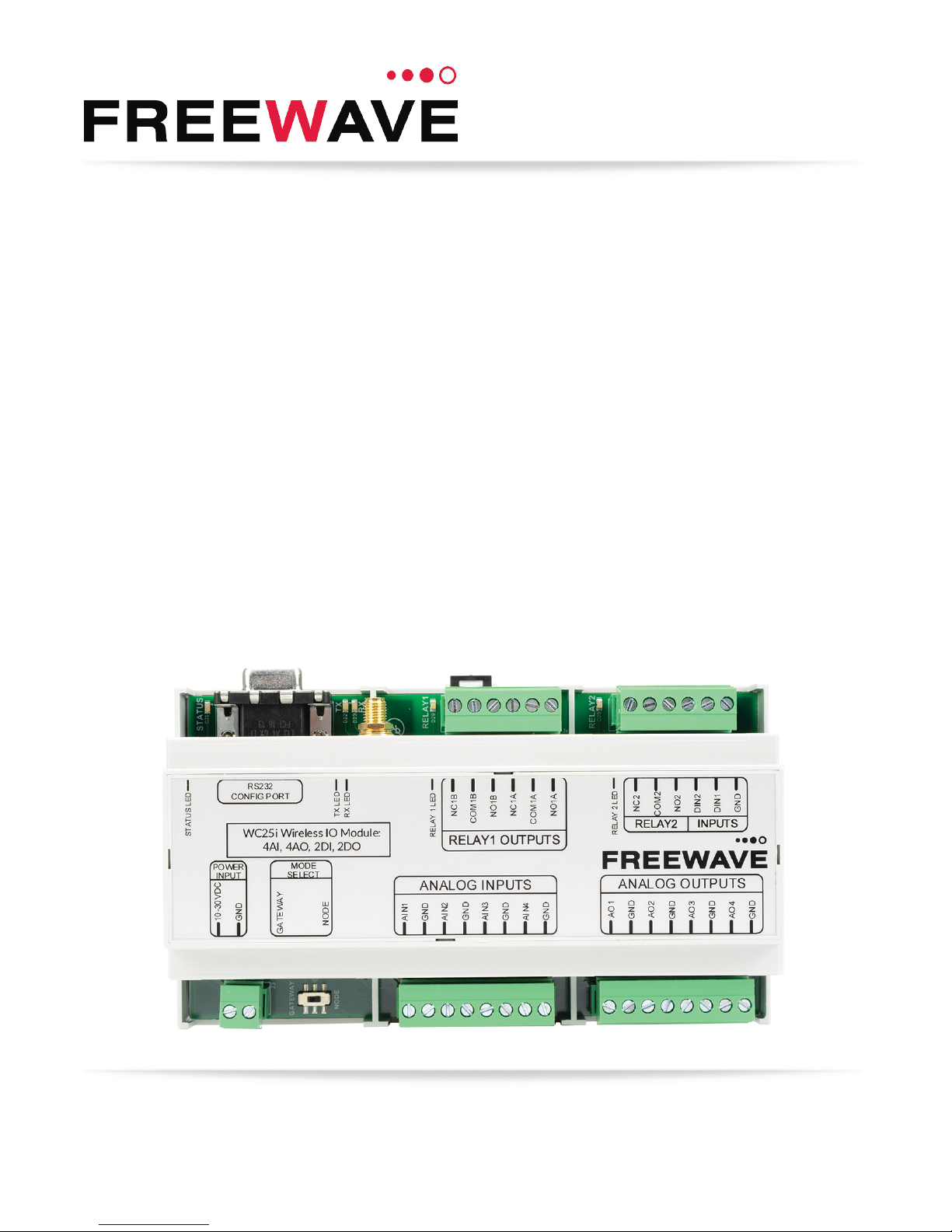
1. Overview - WC25i Wireless I/O Module
Thank you for purchasing the WC25i WirelessI/O Module.
The WC25i Wireless I/O Moduleactsas a wire replacement that replicates analog and digital
signals over a wireless linkbetween a pair of Wireless I/O Modules.
The WC25i has these features:
l 4 Analog Inputs (0-20mA or 0-5V)
l 4 Analog Outputs(0-20mA or 0-5V)
l 2 Digital Inputs
l 2 Relay Outputs (1 DPDT, 1 SPDT)
l Wide range DC power input, +10 to +30VDC
l Low power consumption
l DIN rail mount with pluggable screw terminal blocks
l StatusLEDs
Note: See Available Accessories (on page 77) for additional equipment.
Note: The terms node and Endpoint are used interchangeably in this document.
LUM0083AA Rev Mar-2018 Page 7 of 81 Copyright © 2018FreeWave
This document is the property of FreeWave Technologies, Inc. and contains proprietary information owned by
FreeWave. This document cannot be reproduced in whole or in part by any means without written permission from
FreeWave Technologies, Inc.
Page 8

WC25i Wireless I/O Module: User & Reference Manual
2. Equipment
l Included Equipment - WC25i (on page 9)
l User-suppliedEquipment (on page 9)
LUM0083AA Rev Mar-2018 Page 8 of 81 Copyright © 2018FreeWave
This document is the property of FreeWave Technologies, Inc. and contains proprietary information owned by
FreeWave. This document cannot be reproduced in whole or in part by any means without written permission from
FreeWave Technologies, Inc.
Page 9
2. Equipment
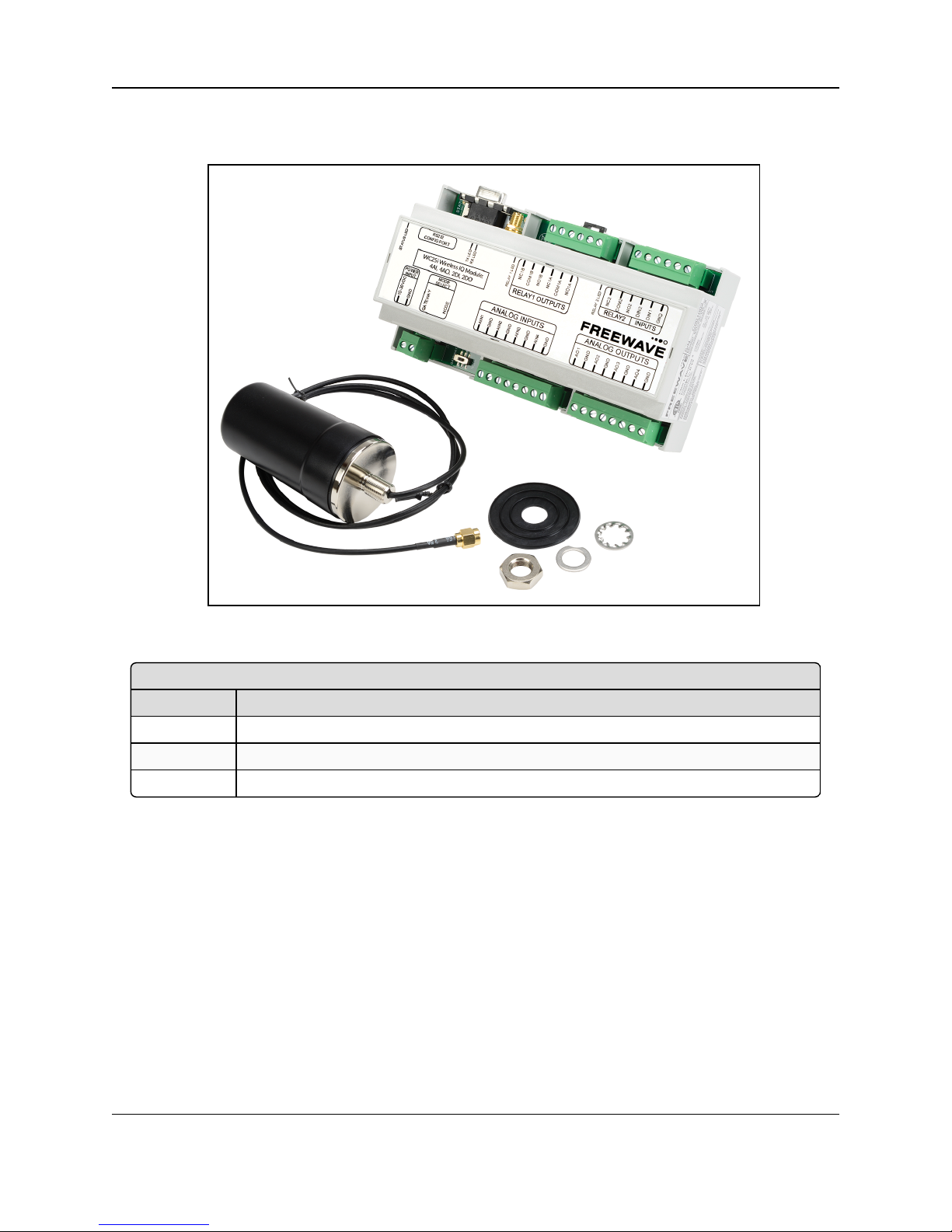
Included Equipment - WC25i
Qty Description
1 WC25i Wireless I/O Module
1 Antenna with gasket and connecting washers
1 WC25i Quick Start Guide
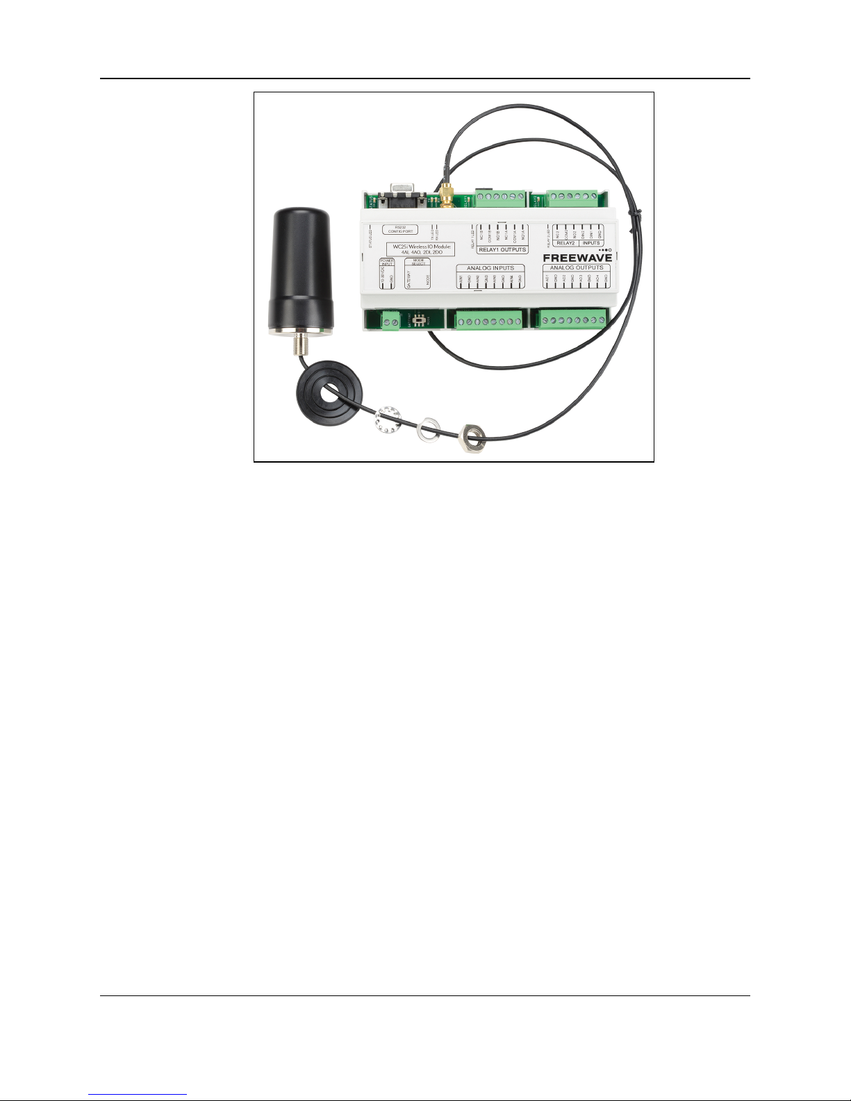
2.1. Included Equipment - WC25i
The WC25i package containsthese items:
Figure 1: WC25i Included Equipment
2.1.1. User-supplied Equipment
l Small, flathead screwdriver
l DC Adapter Power Supply (+10 to +30VDC)
l USB to Serial DB9 programming cable (FreeWave Part #WC-USB-DB9)
l Power supply and Ground wiring
LUM0083AA Rev Mar-2018 Page 9 of 81 Copyright © 2018FreeWave
This document is the property of FreeWave Technologies, Inc. and contains proprietary information owned by
FreeWave. This document cannot be reproduced in whole or in part by any means without written permission from
FreeWave Technologies, Inc.
Page 10

WC25i Wireless I/O Module: User & Reference Manual
3. WC25i Connections
l Connections- WC25i Wireless I/O Module (on page 11)
l Digital Inputs (on page 14)
l Relay 1 Outputs (Digital) (on page 14)
l Analog Outputs (on page 15)
l Analog Inputs (on page 15)
l Hardware Installation (on page 17)
LUM0083AA Rev Mar-2018 Page 10 of 81 Copyright © 2018FreeWave
This document is the property of FreeWave Technologies, Inc. and contains proprietary information owned by
FreeWave. This document cannot be reproduced in whole or in part by any means without written permission from
FreeWave Technologies, Inc.
Page 11
3. WC25i Connections
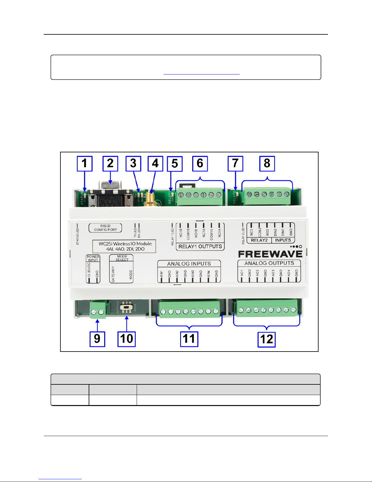
WC25i Wireless I/O Module - Connections
Location # Title Description
1 Status LEDs See LEDs (on page 76) for detailed information.
3.1. Connections - WC25i Wireless I/O Module
Important!: The WC25i Wireless I/O Module is configuredusing the WC Toolkit.
Downloadthe WC Toolkit software from http://support.freewave.com/.
The WC25i providesscrew terminal connections for Analog Inputs / Outputs and Relay (Digital)
Inputs / Outputs.
l Power must be provided by the Power Input screw terminals(+10 to +30VDC)
l The WC25i power requirement at 12VDC is 25mA average plus15mA per energized
relay channel.
l Power required for any attached devices (Analog Inputs / Outputs) is in addition to this.
These are the WC25i connections:
Figure 2: WC25i Wireless I/O Module Connections
LUM0083AA Rev Mar-2018 Page 11 of 81 Copyright © 2018FreeWave
This document is the property of FreeWave Technologies, Inc. and contains proprietary information owned by
FreeWave. This document cannot be reproduced in whole or in part by any means without written permission from
FreeWave Technologies, Inc.
Page 12

WC25i Wireless I/O Module: User & Reference Manual
WC25i Wireless I/O Module - Connections
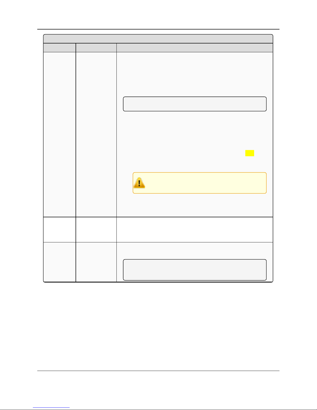
Location # Title Description
2 RS232 Config
/ Debug
connector
The RS232 Config / Debug connector is for the USB to Serial DB9
programming cable (FreeWave Part # WC-USB-DB9).
3 Tx and Rx
LEDs
See LEDs (on page 76) for detailed information.
4 Antenna Port The antenna port is standard SMA connector.
Note: Connect this port to a suitable 900MHz antenna.
5 Relay 1 LED See LEDs (onpage 76) for detailed information.
6 Relay 1
Outputs
Note: See Relay 1 Outputs (Digital) (on page 14).
l WC25i Single Endpoint configuration- The two Digital Outputs
arean SPDT relay and a DPDT relay.
l The state of the relays is controlled using Modbus write
commands from the master Modbus device connected to the
Gateway.
Alternatively, the relays can be controlled using
the RSD settings on the Gateway.
l WC25i System configuration - The two Digital Outputs are an
SPDT relay and a DPDT relay.
7 Relay 2 LED See LEDs (onpage 76) for detailed information.
LUM0083AA Rev Mar-2018 Page 12 of 81 Copyright © 2018FreeWave
This document is the property of FreeWave Technologies, Inc. and contains proprietary information owned by
FreeWave. This document cannot be reproduced in whole or in part by any means without written permission from
FreeWave Technologies, Inc.
Page 13
3. WC25i Connections
WC25i Wireless I/O Module - Connections
Location # Title Description
8 Relay 2
Digital Inputs
Relay 2
l NC2 - Closed relay connection for Channel 2.
l COM2 - Common relay connection for Channel 2.
l NO2 - Opened relation connection for Channel 2.
Inputs
Note: See Digital Inputs (on page 14).
l WC25i Single Endpoint configuration- The two Digital Inputs
areread and forwarded to the Gateway at the interval selected in
the Checkin Interval list box in the Device Configuration
window (on page 52).
l Each input is totalized and the frequency is reported.
l If the State Change Checkin list box selection is Yes
(enabled), all readings (analog and digital) are sent to the
WC45i-Gateway immediately.
Caution: Do not enable the State Change
Checkin list box for rapidly changing inputs.
l WC25i System configuration - Whenever Digital Input 1 or
Digital Input 2 is closed on one of the WC25is, Relay 1 or Relay
2 is energized on the other WC25i.
9 Power Input
PWR
GND
Power Source from an external power supply of +10 to +30VDC.
External power ground.
10 Gateway -
Node switch
The Gateway - Node switch designates the WC25i as either a
Gateway or Endpoint.
Note: The terms node and Endpoint are used
interchangeably in this document.
LUM0083AA Rev Mar-2018 Page 13 of 81 Copyright © 2018FreeWave
This document is the property of FreeWave Technologies, Inc. and contains proprietary information owned by
FreeWave. This document cannot be reproduced in whole or in part by any means without written permission from
FreeWave Technologies, Inc.
Page 14

WC25i Wireless I/O Module: User & Reference Manual
WC25i Wireless I/O Module - Connections
Location # Title Description
11 Analog Inputs
Note: See Analog Inputs (on page 15) to designate the
WC25i as either mA or Volts.
l WC25i Single Endpoint configuration- The four Analog Inputs
(AIN1-AIN4) on the Endpoint are read and forwarded to the
Gateway at the interval selected in the Checkin Interval list box
in the Device Configuration window (on page 52).
l WC25i System configuration - The four Analog Inputs (AIN1-
AIN4) on the Endpoint aremirrored wirelessly to the four Analog
Outputs (AO1-AO4) on each WC25i.
12 Analog Outputs
Note: See Analog Outputs (onpage 15) to designate the
WC25i as either mA or Volts.
l WC25i Single Endpoint configuration- The four Analog
Outputs (AO1-AO4) on the Endpoint are controlled using Modbus
write commands from the master Modbus device connected to
the Gateway.
l The Analog Outputs are always written in μA even when the
switch is set for a 1-5V output.
l It is up to the PLC to convert the readings to voltage.
l WC25i System configuration - The four Analog Inputs (AIN1-
AIN4) on the Endpoint aremirrored wirelessly to the four Analog
Outputs (AO1-AO4) on each WC25i.
3.1.1. Digital Inputs
The two Digital Inputs (DIN 1 and DIN 2) can be dry contact or voltage (must be push-pull with 30
Volts maximum).
Important!: Verify the connection to the ground bus from the moduleis to either the groundof the
voltage device or the dry contact.
3.1.2. Relay 1 Outputs (Digital)
There are two relay outputs:
l Relay 1 Output is a DPDT
l Relay 2 Output is an SPDT.
l These relays are rated for:
l 30 VDC @ 2 Amps
l 250 VAC @ 0.25 Amps
LUM0083AA Rev Mar-2018 Page 14 of 81 Copyright © 2018FreeWave
This document is the property of FreeWave Technologies, Inc. and contains proprietary information owned by
FreeWave. This document cannot be reproduced in whole or in part by any means without written permission from
FreeWave Technologies, Inc.
Page 15
3. WC25i Connections
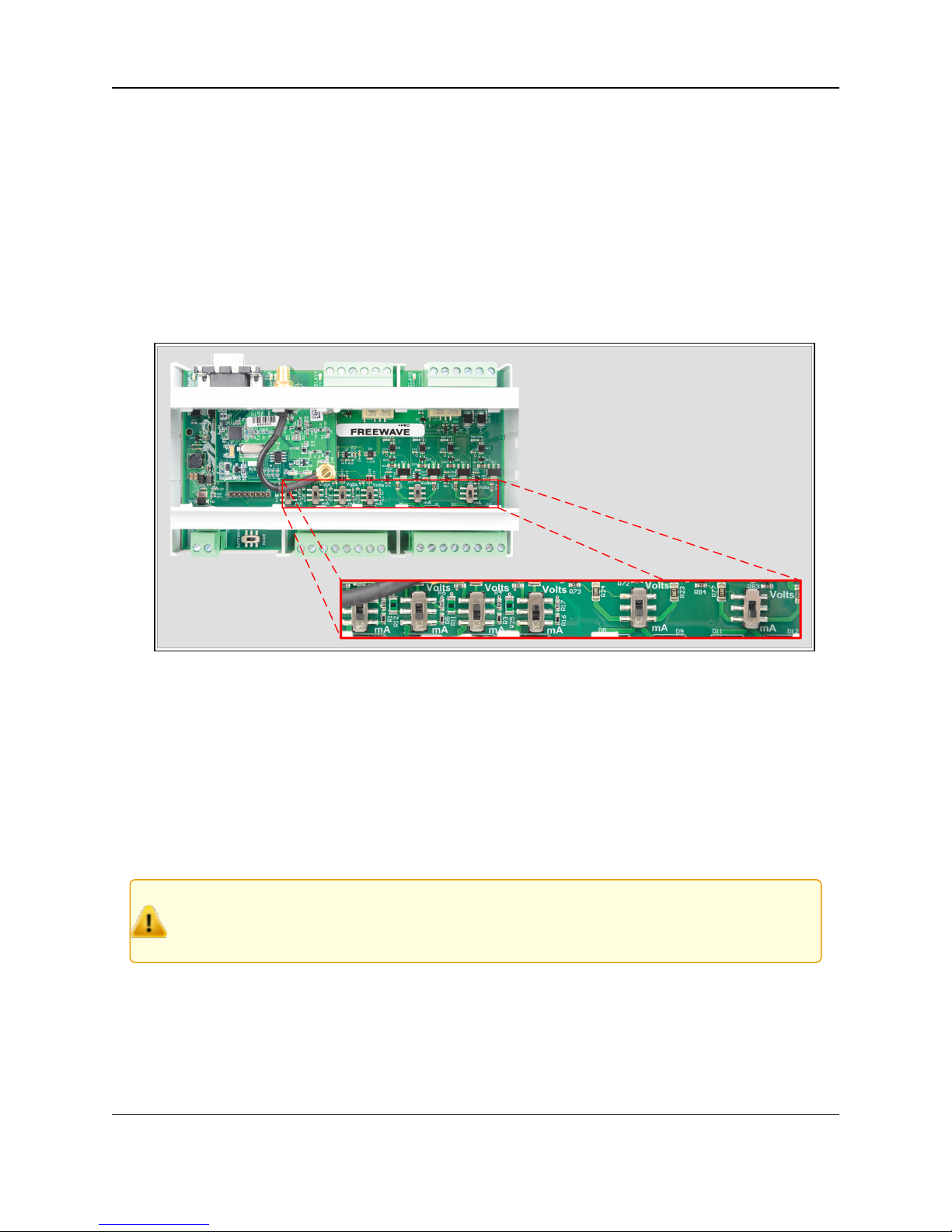
3.1.3. Analog Outputs
In (Figure 3), each switch controls the output mode for a pair of outputs.
l The switch on the left sets both Output 1 (AO1) and Output 2 (AO2) to either mA or Volts.
l The switch on the right sets both Output 3 (AO3) and Output 4 (AO4) to either mA or Volts.
l In mA output mode, the compliance voltage is the Endpoint supply voltage.
3.1.4. Analog Inputs
The Analog Inputs may operate in either Current (0-20mA / 4-20mA) or Voltage (0-5V / 1-5V).
The input mode is set usingslide switches inside the WC25i (Figure 3).
Figure 3: WC25i Switches
1. Use the Small, flathead screwdriver to remove the cover of the WC25i.
The cover is held on by clips.
2. Slide the switch corresponding to the input channel to:
l Volts for a Voltage Input.
l mA for a Current Input.
3. Wire the analog voltage or current to the set of screw terminal connections.
4. Replacethe WC25i cover.
Caution: Maximum input voltage (for eitherCurrent or Voltageinput mode) is 10 Volts.
The compliance voltage for a 4-20mA device must be provided externally.
See the Example: Analog Inputs Wiring Diagram (on page 16) for details.
LUM0083AA Rev Mar-2018 Page 15 of 81 Copyright © 2018FreeWave
This document is the property of FreeWave Technologies, Inc. and contains proprietary information owned by
FreeWave. This document cannot be reproduced in whole or in part by any means without written permission from
FreeWave Technologies, Inc.
Page 16
WC25i Wireless I/O Module: User & Reference Manual
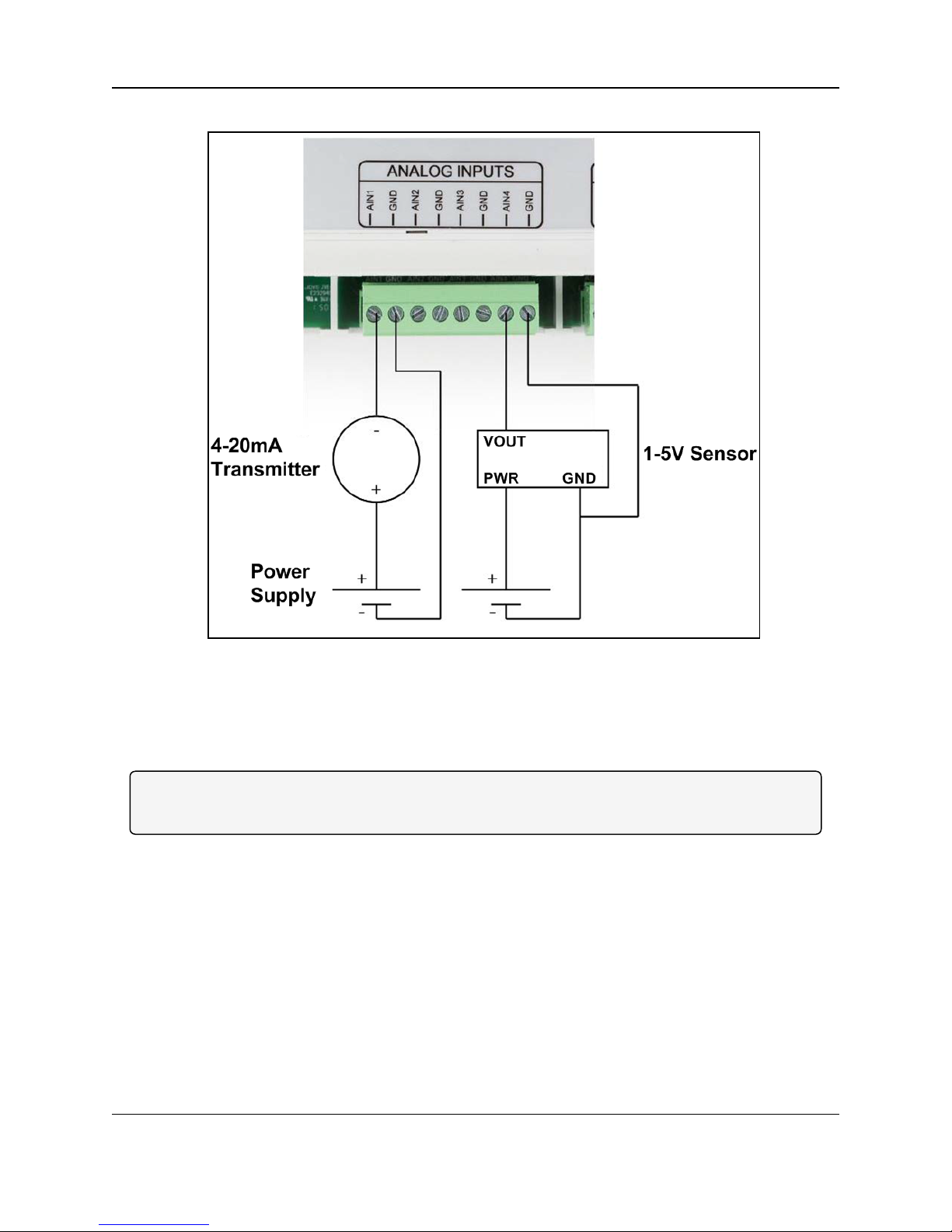
Example: Analog Inputs Wiring Diagram
Figure 4: Example: Analog Inputs Wiring Diagram
Figure 4 is an example of a:
l 4-20mA transmitter connected to AIN1.
l 1-5V sensor connected to AIN4.
Note: Generally the same power supply used to power the WC25i is used to provide power for the
attached sensors.
LUM0083AA Rev Mar-2018 Page 16 of 81 Copyright © 2018FreeWave
This document is the property of FreeWave Technologies, Inc. and contains proprietary information owned by
FreeWave. This document cannot be reproduced in whole or in part by any means without written permission from
FreeWave Technologies, Inc.
Page 17

3. WC25i Connections
3.2. Hardware Installation
Important!: Verify the items listed in Equipment (on page 8) are availablebefore starting this
procedure.
It is assumed that the readerand installer have completed the FreeWave installationand setup
training to follow the procedures in this document.
1. All wiring should be neat and orderly.
2. Connect the Power supply and Ground wiring to the Power Input terminal block. (#9 in
Connections - WC25i WirelessI/O Module (on page 11))
3. Connect the Serial end of the WC-USB-DB9 cable to the RS232 Config / Debug
connector port and the USB connection to the computer.
4. If this is the first time the WC25i is installed, wait for the drivers to install.
Important!: Depending on the computer and connection, the driverinstallationcan take 3-6
minutes.
5. Completethese procedures:
a. WC Toolkit Installation (on page 19)
b. WC Toolkit Update (on page 26)
c. Configuration - Single WC25i Endpoint (on page 29)
or
Configuration - WC25i System (on page 36).
6. When the WC25i configuration is completed:
a. Connect the enclosed Antenna with gasket and connecting washers to the WC25i
(Figure 5).
b. Install the WC25i and connectedantenna in a secure location.
LUM0083AA Rev Mar-2018 Page 17 of 81 Copyright © 2018FreeWave
This document is the property of FreeWave Technologies, Inc. and contains proprietary information owned by
FreeWave. This document cannot be reproduced in whole or in part by any means without written permission from
FreeWave Technologies, Inc.
Page 18
WC25i Wireless I/O Module: User & Reference Manual
Figure 5: WC25i Connection
LUM0083AA Rev Mar-2018 Page 18 of 81 Copyright © 2018FreeWave
This document is the property of FreeWave Technologies, Inc. and contains proprietary information owned by
FreeWave. This document cannot be reproduced in whole or in part by any means without written permission from
FreeWave Technologies, Inc.
Page 19
WC25i Wireless I/O Module: User & Reference Manual
4. WC Toolkit Installation
Note: The images in this procedure are for Windows® 7 and/or Firefox®.
The dialog boxes and windows may appear differently on each computer.
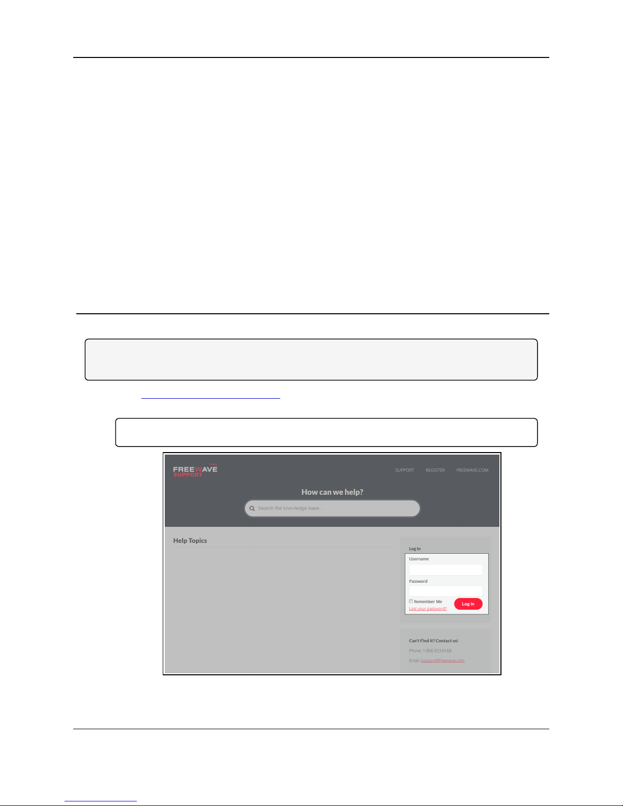
1. Clickhttp://support.freewave.com/.
The FreeWave Support site opens.
Important!: Registration is required to use this website.
2. Enter the User Name and Password.
LUM0083AA Rev Mar-2018 Page 19 of 81 Copyright © 2018FreeWave
This document is the property of FreeWave Technologies, Inc. and contains proprietary information owned by
FreeWave. This document cannot be reproduced in whole or in part by any means without written permission from
Figure 6: FreeWave Login window
FreeWave Technologies, Inc.
Page 20
4. WC Toolkit Installation
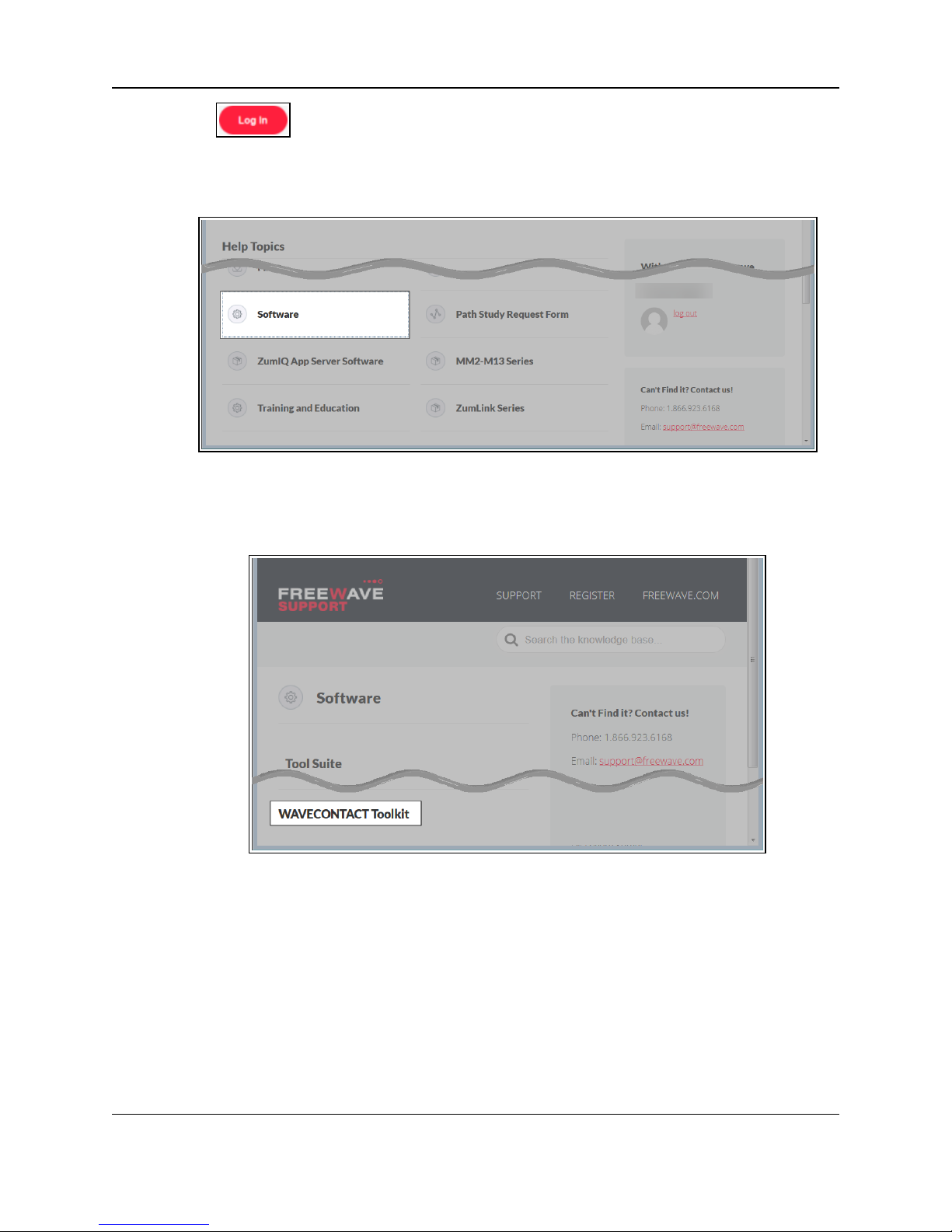
3.
Click .
A successful Login message briefly appears.
The Help Topics window opens.
4. Clickthe Software link.
Figure 7: Help Topics window
The Software window opens.
5. Clickthe WAVECONTACT Toolkit link.
The available software appears in the window.
6. Select and click the attachment.
LUM0083AA Rev Mar-2018 Page 20 of 81 Copyright © 2018FreeWave
This document is the property of FreeWave Technologies, Inc. and contains proprietary information owned by
FreeWave. This document cannot be reproduced in whole or in part by any means without written permission from
Figure 8: Software window
FreeWave Technologies, Inc.
Page 21
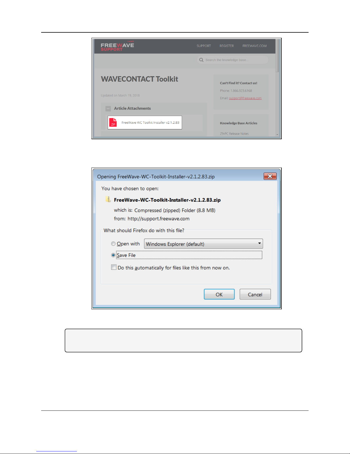
Figure 9: WAVECONTACT Toolkit window
The Opening dialog box opens.
WC25i Wireless I/O Module: User & Reference Manual
Note: This procedure shows Firefox® dialog boxes.
Otherbrowsers will have different dialogboxes andprocedures.
7. ClickOK.
The Enter name of file to save to dialog box opens.
LUM0083AA Rev Mar-2018 Page 21 of 81 Copyright © 2018FreeWave
This document is the property of FreeWave Technologies, Inc. and contains proprietary information owned by
FreeWave. This document cannot be reproduced in whole or in part by any means without written permission from
Figure 10: WC Toolkit Opening dialog box
FreeWave Technologies, Inc.
Page 22
4. WC Toolkit Installation
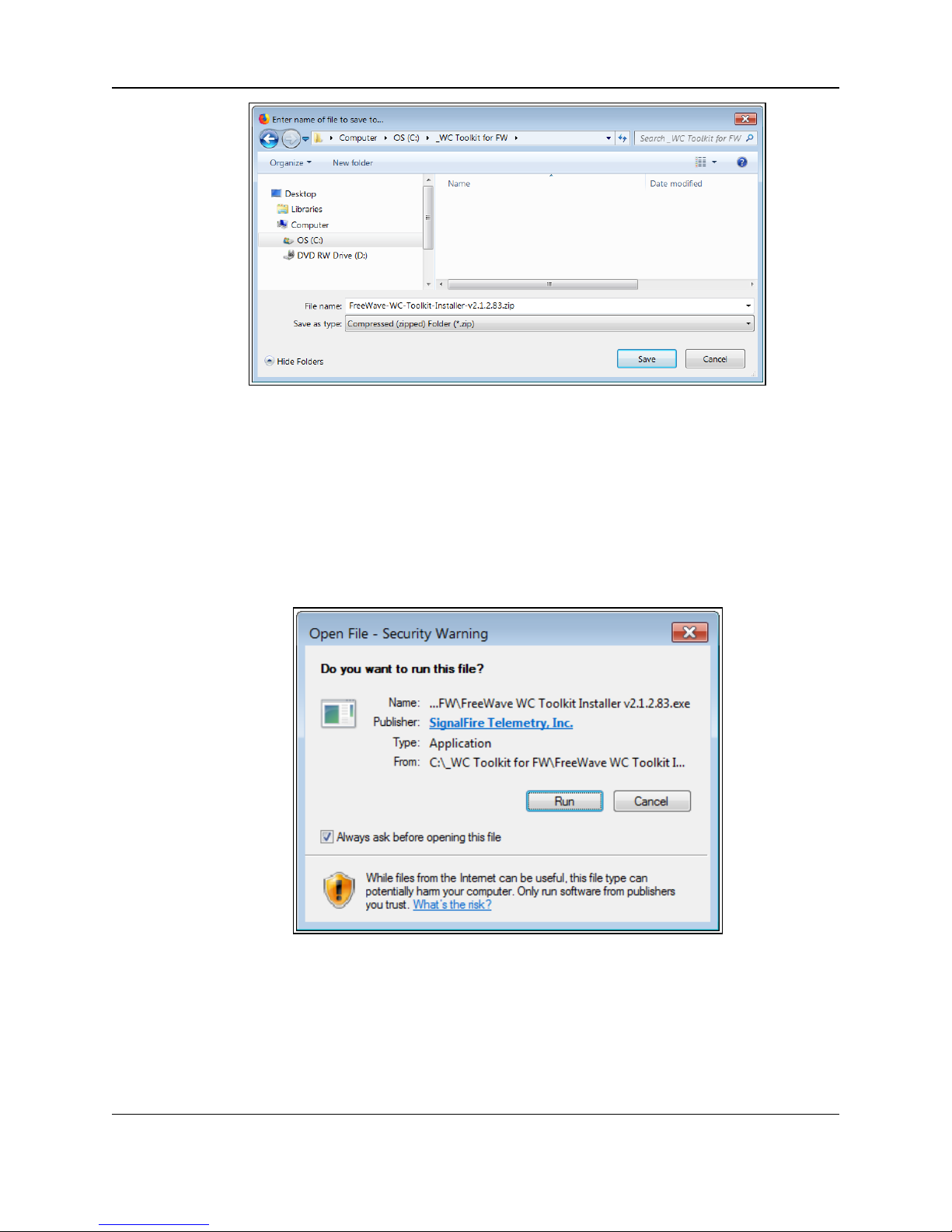
Figure 11: Enter name of file to save to dialog box
8. Search for and select a location to save the .zip file to and click Save.
The Enter name of file to save to dialog box closes.
9. Open a Windows® Explorer window and find the location where the .zip file was saved.
10. Double-click the .zip file.
11. Extract the .exe file from the .zip file into a parent location.
12. Double-click the .exe file to run the WC Toolkit installer.
The Open File - Security Warning dialog box opens.
Figure 12: Open File - Security Warning dialog box
13. ClickRun.
The User Account Control dialog box opens.
LUM0083AA Rev Mar-2018 Page 22 of 81 Copyright © 2018FreeWave
This document is the property of FreeWave Technologies, Inc. and contains proprietary information owned by
FreeWave. This document cannot be reproduced in whole or in part by any means without written permission from
FreeWave Technologies, Inc.
Page 23
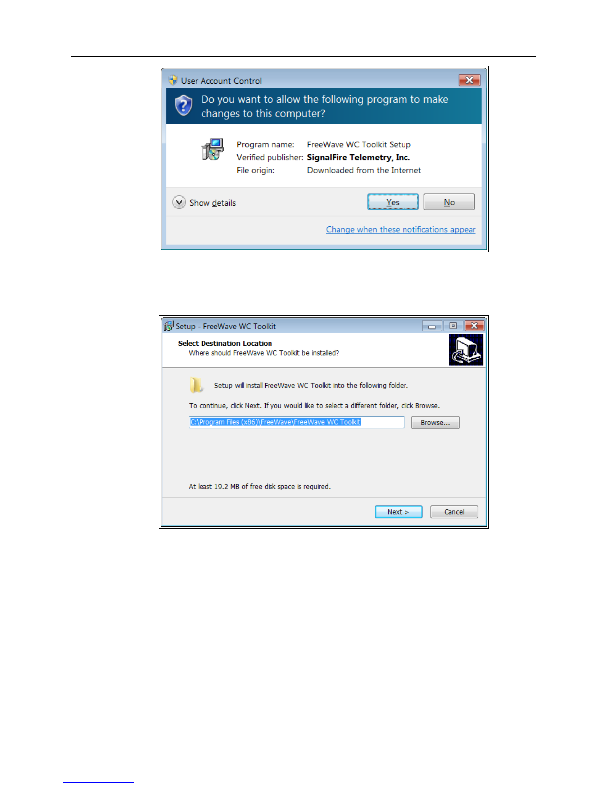
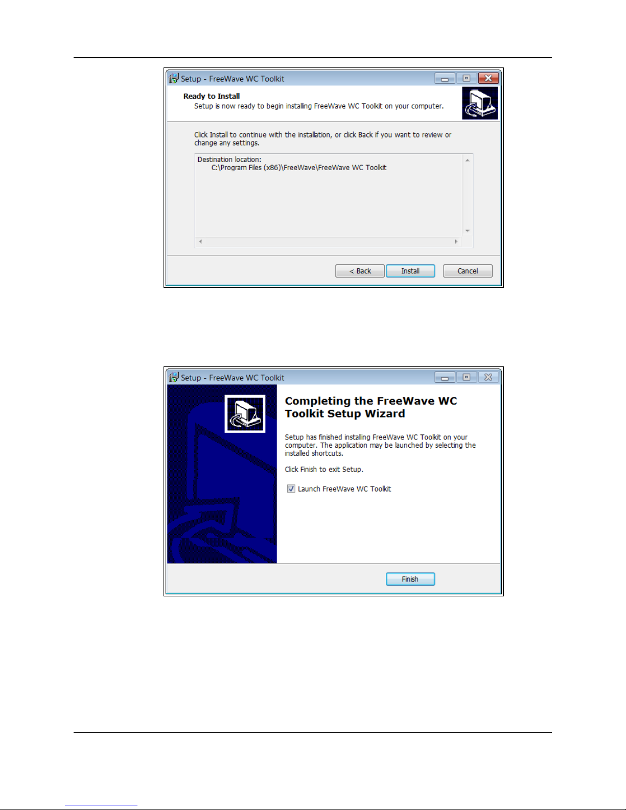
Figure 13: User Account Control dialog box
14. ClickYes.
The WC Toolkit Setup Wizard starts.
WC25i Wireless I/O Module: User & Reference Manual
Figure 14: WC Toolkit Setup Wizard - Select Destination Location window
15. ClickNext to continue.
The Ready to Install window opens.
LUM0083AA Rev Mar-2018 Page 23 of 81 Copyright © 2018FreeWave
This document is the property of FreeWave Technologies, Inc. and contains proprietary information owned by
FreeWave. This document cannot be reproduced in whole or in part by any means without written permission from
FreeWave Technologies, Inc.
Page 24
4. WC Toolkit Installation
Figure 15: WC Toolkit Setup Wizard - Ready to Install window
16. ClickInstall.
The installprocess is very quick.
The Installation Complete window opens.
Figure 16: WC Toolkit Setup Wizard - Installation Complete window
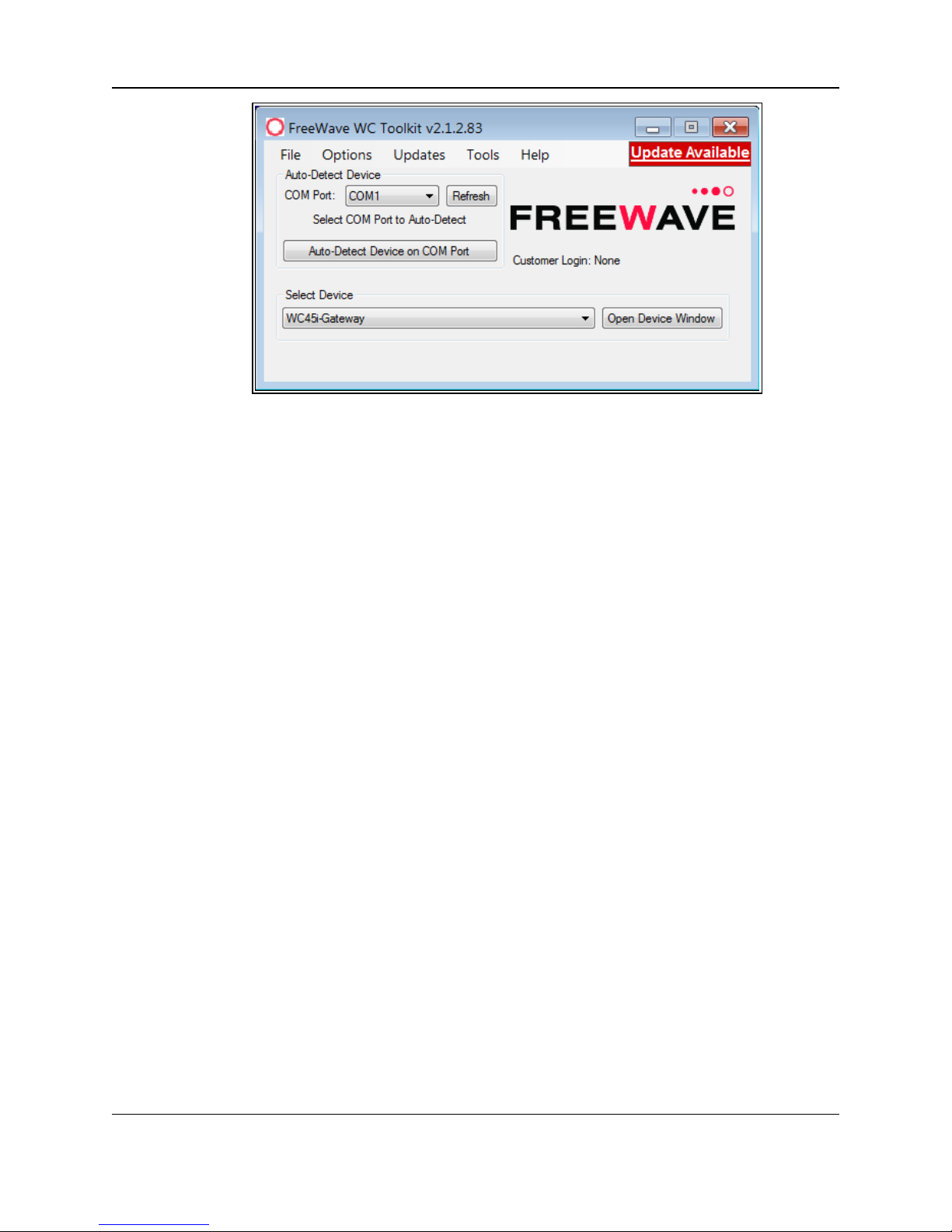
17. ClickFinish to open WC Toolkit.
An Update message appears in the WC Toolkit window is an update is available.
LUM0083AA Rev Mar-2018 Page 24 of 81 Copyright © 2018FreeWave
This document is the property of FreeWave Technologies, Inc. and contains proprietary information owned by
FreeWave. This document cannot be reproduced in whole or in part by any means without written permission from
FreeWave Technologies, Inc.
Page 25
WC25i Wireless I/O Module: User & Reference Manual
Figure 17: WC Toolkit - Update Available message
18. Continue with the WC Toolkit Update (on page 26) procedure.
LUM0083AA Rev Mar-2018 Page 25 of 81 Copyright © 2018FreeWave
This document is the property of FreeWave Technologies, Inc. and contains proprietary information owned by
FreeWave. This document cannot be reproduced in whole or in part by any means without written permission from
FreeWave Technologies, Inc.
Page 26

WC25i Wireless I/O Module: User & Reference Manual
5. WC Toolkit Update
If the WAVECONTACT device is connected to the internet, WC Toolkit automaticallysearches for
an update for either the WC Toolkit itself or the connected device's firmware.
An Update Available message appears if an update is available.
Note: An Update Available message also appears in the Device Configuration window (onpage 52)
for any connected WAVECONTACT device when an update is availablefor that device.
The update procedure is the same for the device and WC Toolkit.
1. Open the WC Toolkit software.
The Update Available message appears in the window. (Figure 18)
Figure 18: WC Toolkit - Update Available message
LUM0083AA Rev Mar-2018 Page 26 of 81 Copyright © 2018FreeWave
This document is the property of FreeWave Technologies, Inc. and contains proprietary information owned by
FreeWave. This document cannot be reproduced in whole or in part by any means without written permission from
FreeWave Technologies, Inc.
Page 27

5. WC Toolkit Update
2. Clickthe Update Available message link.
Figure 19: Click the Update Available message link
The Open File - Security Warning dialog box opens.
Figure 20: Open File - Security Warning dialog box
3. ClickRun.
The User Account Control dialog box opens.
LUM0083AA Rev Mar-2018 Page 27 of 81 Copyright © 2018FreeWave
This document is the property of FreeWave Technologies, Inc. and contains proprietary information owned by
FreeWave. This document cannot be reproduced in whole or in part by any means without written permission from
FreeWave Technologies, Inc.
Page 28

WC25i Wireless I/O Module: User & Reference Manual
Figure 21: User Account Control dialog box
4. ClickYes.
The WC Toolkit update processis very quick.
When the update is completed, WC Toolkit re-opens the Select Device window showing
the updated software version in the WC Toolkit window. (Figure 22)
5. Continue with Configuration of the WC25i.
LUM0083AA Rev Mar-2018 Page 28 of 81 Copyright © 2018FreeWave
This document is the property of FreeWave Technologies, Inc. and contains proprietary information owned by
FreeWave. This document cannot be reproduced in whole or in part by any means without written permission from
Figure 22: Select Device window
FreeWave Technologies, Inc.
Page 29

WC25i Wireless I/O Module: User & Reference Manual
6. Configuration - Single WC25i Endpoint
Note: The terms node and Endpoint are used interchangeably in this document.
FREEWAVE Recommends: Install and configurethe WC45i Gateway before any Endpoints to
ensure the Endpoints have connectivity after installation.
Important!: The WC25i Wireless I/O Module is configuredusing the WC Toolkit.
Downloadthe WC Toolkit software from http://support.freewave.com/.
Procedure
Note: The screenshots are examples only.
The dialog boxes and windows appear differently on each computer.
1. Verify the WC Toolkit software is installed on the computer connected to the WC25i.
Note: See WC Toolkit Installation (on page 19) and WC Toolkit Update (on page 26).
2. On the WC25i, slide the Gateway - Node switch to the Node side. (Connections - WC25i
WirelessI/O Module (on page 11), #10)
3. Connect the Power supply and Ground wiring to the Power Input terminal block.
4. Power cycle the Endpoint (slave) WC25i for the change to take effect.
5. Connect the Serial end of the WC-USB-DB9 cable to the RS232 Config / Debug
connector port and the USB connection to the computer.
6. Open the WC Toolkit software.
The Select Device window opens.(Figure 23)
LUM0083AA Rev Mar-2018 Page 29 of 81 Copyright © 2018FreeWave
This document is the property of FreeWave Technologies, Inc. and contains proprietary information owned by
FreeWave. This document cannot be reproduced in whole or in part by any means without written permission from
FreeWave Technologies, Inc.
Page 30

6. Configuration - Single WC25i Endpoint
Figure 23: Select Device window
7. Clickthe Refresh button to have WC Toolkit search for and list the available COM ports
reported by Windows and connected devices in the COM Port list box.
8. Clickthe COM Port list box arrow and select the COM port on the computer associated
with the connected WC25i.
9. Clickthe Auto-Detect Device on COM Port button to have WC Toolkit connect the
device to the COM Port selected in the COM Port list box.
Note: Optional: Click the Select Device list box arrow and select the connected WC25i
device.
LUM0083AA Rev Mar-2018 Page 30 of 81 Copyright © 2018FreeWave
This document is the property of FreeWave Technologies, Inc. and contains proprietary information owned by
FreeWave. This document cannot be reproduced in whole or in part by any means without written permission from
FreeWave Technologies, Inc.
Page 31

WC25i Wireless I/O Module: User & Reference Manual
Figure 24: Select Device list box
The Device Configuration window opens for the selected device.
Note: See Device Configuration window (on page 52) for detailed information.
LUM0083AA Rev Mar-2018 Page 31 of 81 Copyright © 2018FreeWave
This document is the property of FreeWave Technologies, Inc. and contains proprietary information owned by
FreeWave. This document cannot be reproduced in whole or in part by any means without written permission from
FreeWave Technologies, Inc.
Page 32

6. Configuration - Single WC25i Endpoint
Figure 25: Device Configuration window: WC25i
10. In the Reported Module Values area (#3):
a. In the Set Output 1 to 4 text boxes, enter the number of milliampsto assign to the
Analog Outputs.
Example: For 8 milliamps, enter8000 in the Set Output 1 to 4 text boxes.
b. Clickthe Relay 1 or Relay 2 Energize button to manually test (energize) the relays.
c. Clickthe Relay 1 or Relay 2 De-Energize button to manuallytest (de-energize) the
relays.
11. In the Set Encryption Key area (#5), change these settings:
a. In the Key text box, enter the encryptionkeyfor the device using 6 to 16 characters.
b. Clickthe Set button to save the information.
Important!: A Key CANNOT contain spaces or angle brackets.
The Gateway andEndpoints only communicate if they areconfigured with the same Key.
When setting up a new network, use this same encryption Key on all the devices.
Note: When the WC25i drops its network, it attempts to join networks using the same
encryption Key.
LUM0083AA Rev Mar-2018 Page 32 of 81 Copyright © 2018FreeWave
This document is the property of FreeWave Technologies, Inc. and contains proprietary information owned by
FreeWave. This document cannot be reproduced in whole or in part by any means without written permission from
FreeWave Technologies, Inc.
Page 33

WC25i Wireless I/O Module: User & Reference Manual
Caution: It is possible to hide the encryption Key so it cannot be read.
This is the most secure option, but if the Key is forgotten, there is no way to recover it.
The Key must be reset on every device on the network.
12. Optional: Clickthe Settings menu and select Set Encryption Key Unrecoverable to
permanently hide the key.
13. In the Settings area (#6), change these settings:
Note: The Network settings are used to create separate networks using multiple Gateways
(that are in close proximity to oneanother).
Important!: The Radio Network andRadio Network Group settings are selected by the
user but MUST MATCH between each pairof WC25is for the WC25is to communicate.
See WAVECONTACT Network Frequencies (on page 64) for additional information.
a. Clickthe Radio Range list box arrow and select either Long Range or Short Range.
b. Clickthe Set button to save the information.
c. In the Slave ID column/ text box, enter the remote source Endpoint Modbus Slave ID.
Note: Each remote device connected to the Gateway MUST have a unique Modbus
Slave ID (1-240). See: Modbus Registers - WC25i (on page 47)
Important!: Verify there are no duplicate Slave IDs in a given network.
The Gateway only caches oneset of data for each Slave ID.
A duplicate is overwritten.
d. Clickthe Set button to save the information.
e. Optional: In the Node Name text box, enter a name for the Endpoint using a maximum
of 10 characters.
f. Click the Set button to savethe information.
g. Clickthe Radio Network list box arrow and select 0 (zero) to 7 for the assigned
number.
h. Clickthe Set button to save the information.
i. Clickthe Radio Network Group list box arrow and select 0 (zero) to 29 for the network
group assigned number.
Important!: The Radio Network andRadio Network Group settings are selected by
the user but MUST MATCH between each pair of WC25is for the WC25is to
communicate.
See WAVECONTACT Network Frequencies (on page 64) for additional information.
j. Clickthe Set button to save the information.
k. Clickthe Checkin Interval list box arrow and select how often the Endpoint wakes up,
reads the sensor values, and transmits the data to the Gateway.
LUM0083AA Rev Mar-2018 Page 33 of 81 Copyright © 2018FreeWave
This document is the property of FreeWave Technologies, Inc. and contains proprietary information owned by
FreeWave. This document cannot be reproduced in whole or in part by any means without written permission from
FreeWave Technologies, Inc.
Page 34

6. Configuration - Single WC25i Endpoint
l. Clickthe Set button to save the information.
m. Clickthe State Change Checkin list box arrow and select Yes to checkon a changeof
state at the input rather than waiting for the check in time to expire.
n. Clickthe Set button to save the information.
o. Clickthe Communication Failsafe Timer (min) list box arrow and select the time to
set the outputs to a de-energizedstate if the link is lost with the Gateway after the set
time.
p. Clickthe Set button to save the information.
q. Clickthe Message Failsafe Timer (min) list box arrow and select the time since a
valid Modbus coil write message or Analog Output write has been sent from the
Modbusmaster through the Gateway.
Caution: If a time is selected in the Message Failsafe Timer (min) list box, the
time entered must be set higher than the Modbus Coil Write and Analog Output
Write frequency of the Modbus master device.
r. Click the Set button to save the information.
14. Optional: In the Analog Scaling area (#7), customize the reported Analog Input to
engineering units.
a. In the Scale Low (units) text boxes, manuallyenter the Input 1 to 4 lower range
value.
b. In the Scale High (units) text boxes, manually enter the Input 1 to 4 upper range
value.
c. In the Scale Adjust (+/-) text box, enter an offset to add to or subtract from the
reported scaled value.
d. Clickthe Set Analog Scaling button to save the information.
15. Optional: In the Relay Outputs area (#8), click either the Failsafe Enabled Relay 1 or
Relay 2 check boxesto set the relay to the un-energized state if there is a communication
error (lossof communications).
16. Clickthe Set Failsafe Options button to save the information.
17. Optional: In the Analog Outputs area (#9):
a. Clickthe Fail Value Enable check box for Output 1 to 4 to enable the milliamp value
entered in the associated Fail with Output Value text box.
b. In the Fail with Output Value column / text box, enter the milliamp value the WC25i
must reach to stop receivingthe control signal.
c. Clickthe Set Fail Output Value button to save the information.
18. Verify the Gateway is communicating with the Endpoints.
Note: A successful connection on the WAVECONTACT Endpoint is indicatedwith Green
blinking TX and ACT lights and a Red blinking light for RX.
If the connection is NOT successful, a Green blinking TX light appears for 10 seconds.
LUM0083AA Rev Mar-2018 Page 34 of 81 Copyright © 2018FreeWave
This document is the property of FreeWave Technologies, Inc. and contains proprietary information owned by
FreeWave. This document cannot be reproduced in whole or in part by any means without written permission from
FreeWave Technologies, Inc.
Page 35

WC25i Wireless I/O Module: User & Reference Manual
FREEWAVE Recommends: Install and configurethe WC45i Gateway before any
Endpoints to ensure the Endpoints have connectivity after installation.
19. Optional: Continue with:
l Digital Input Debounce (on page 43)
l Digital Input State Latch (on page 45)
20. Close the WC Toolkit software.
21. Removethe WC-USB-DB9 USB to Serial DB9 programming cable from the computer and
the RS232 Config / Debug connector port.
22. Install the WC25i and connected antenna in a secure location.
LUM0083AA Rev Mar-2018 Page 35 of 81 Copyright © 2018FreeWave
This document is the property of FreeWave Technologies, Inc. and contains proprietary information owned by
FreeWave. This document cannot be reproduced in whole or in part by any means without written permission from
FreeWave Technologies, Inc.
Page 36

WC25i Wireless I/O Module: User & Reference Manual
7. Configuration - WC25i System
Note: The terms node and Endpoint are used interchangeably in this document.
FREEWAVE Recommends: Install and configurethe WC45i Gateway before any Endpoints to
ensure the Endpoints have connectivity after installation.
l For each pair of WC25is:
l One WC25i must be designatedas the Gateway (master).
l One must be designated as the Endpoint (slave).
Important!: The WC25i Wireless I/O Module is configuredusing the WC Toolkit.
Downloadthe WC Toolkit software from http://support.freewave.com/.
Procedure
Note: The screenshots are examples only.
The dialog boxes and windows appear differently on each computer.
1. Verify the WC Toolkit software is installed on the computer connected to the WC25i.
Note: See WC Toolkit Installation (on page 19) and WC Toolkit Update (on page 26).
2. Verify the Gateway is installed and configured before continuing with the Endpoint
configuration.
3. Select one of the WC25i devices and verify the Gateway - Node switch is toward the
Gateway side. (Connections- WC25i Wireless I/O Module (on page 11), #10)
LUM0083AA Rev Mar-2018 Page 36 of 81 Copyright © 2018FreeWave
This document is the property of FreeWave Technologies, Inc. and contains proprietary information owned by
FreeWave. This document cannot be reproduced in whole or in part by any means without written permission from
FreeWave Technologies, Inc.
Page 37

7. Configuration - WC25i System
4. On the other WC25i, slide the Gateway - Node switch to the Node side.
5. Connect the Power supply and Ground wiring to the Power Input terminal block.
6. Power cycle the Endpoint (slave) WC25i for the change to take effect.
7. Connect the Serial end of the WC-USB-DB9 cable to the RS232 Config / Debug
connector port and the USB connection to the computer.
8. Open the WC Toolkit software.
The Select Device window opens. (Figure 26)
Figure 26: Select Device window
9. Clickthe Refresh button to have WC Toolkit search for and list the available COM ports
reported by Windows and connected devices in the COM Port list box.
10. Clickthe COM Port list box arrow and select the COM port on the computer associated
with the connected WC25i.
11. Clickthe Auto-Detect Device on COM Port button to have WC Toolkit connect the
device to the COM Port selected in the COM Port list box.
Note: Optional: Click the Select Device list box arrow and select the connected WC25i
device.
LUM0083AA Rev Mar-2018 Page 37 of 81 Copyright © 2018FreeWave
This document is the property of FreeWave Technologies, Inc. and contains proprietary information owned by
FreeWave. This document cannot be reproduced in whole or in part by any means without written permission from
FreeWave Technologies, Inc.
Page 38

WC25i Wireless I/O Module: User & Reference Manual
Figure 27: Select Device list box
The Device Configuration window opens for the selected device.
Note: See Device Configuration window (on page 52) for detailed information.
LUM0083AA Rev Mar-2018 Page 38 of 81 Copyright © 2018FreeWave
This document is the property of FreeWave Technologies, Inc. and contains proprietary information owned by
FreeWave. This document cannot be reproduced in whole or in part by any means without written permission from
FreeWave Technologies, Inc.
Page 39

7. Configuration - WC25i System
Figure 28: Device Configuration window: WC25i
12. In the Reported Module Values area (#3)
a. In the Set Output 1 to 4 text boxes, enter the number of milliampsto assign to the
Analog Outputs.
b. Clickthe Relay 1 or Relay 2 Energize button to manually test (energize) the relays.
c. Clickthe Relay 1 or Relay 2 De-Energize button to manuallytest (de-energize) the
relays.
13. In the Set Encryption Key area (#5), change these settings:
a. In the Key text box, enter the encryptionkeyfor the device using 6 to 16 characters.
b. Clickthe Set button to save the information.
Important!: A Key CANNOT contain spaces or angle brackets.
The Gateway andEndpoints only communicate if they areconfigured with the same Key.
When setting up a new network, use this same encryption Key on all the devices.
Note: When the WC25i drops its network, it attempts to join networks using the same
encryption Key.
Caution: It is possible to hide the encryption Key so it cannot be read.
This is the most secure option, but if the Key is forgotten, there is no way to recover it.
The Key must be reset on every device on the network.
LUM0083AA Rev Mar-2018 Page 39 of 81 Copyright © 2018FreeWave
This document is the property of FreeWave Technologies, Inc. and contains proprietary information owned by
FreeWave. This document cannot be reproduced in whole or in part by any means without written permission from
FreeWave Technologies, Inc.
Page 40

WC25i Wireless I/O Module: User & Reference Manual
14. Optional: Clickthe Settings menu and select Set Encryption Key Unrecoverable to
permanently hide the key.
15. In the Settings area (#6), change these settings:
Note: The Network settings are used to create separate networks using multiple Gateways
(that are in close proximity to oneanother).
Important!: The Radio Network andRadio Network Group settings are selected by the
user but MUST MATCH between each pairof WC25is for the WC25is to communicate.
See WAVECONTACT Network Frequencies (on page 64) for additional information.
a. Clickthe Radio Range list box arrow and select either Long Range or Short Range.
b. Clickthe Set button to save the information.
c. Optional: In the Slave ID column / text box, enter the remote source Endpoint Modbus
Slave ID.
Note: Each remote device connected to the Gateway MUST have a unique Modbus
Slave ID (1-240). See: Modbus Registers - WC25i (on page 47)
Important!: Verify there are no duplicate Slave IDs in a given network.
The Gateway only caches oneset of data for each Slave ID.
A duplicate is overwritten.
d. Clickthe Set button to save the information.
e. Optional: In the Node Name text box, enter a name for the Endpoint using a maximum
of 10 characters.
f. Click the Set button to savethe information.
g. Clickthe Radio Network list box arrow and select 0 (zero) to 7 for the assigned
number.
h. Clickthe Set button to save the information.
i. Clickthe Radio Network Group list box arrow and select 0 (zero) to 29 for the network
group assigned number.
Important!: The Radio Network andRadio Network Group settings are selected by
the user but MUST MATCH between each pair of WC25is for the WC25is to
communicate.
See WAVECONTACT Network Frequencies (on page 64) for additional information.
j. Clickthe Set button to save the information.
k. Clickthe Checkin Interval list box arrow and select how often the Endpoint wakes up,
reads the sensor values, and transmits the data to the Gateway.
l. Clickthe Set button to save the information.
m. Clickthe State Change Checkin list box arrow and select Yes to checkon a changeof
state at the input rather than waiting for the check in time to expire.
n. Clickthe Set button to save the information.
LUM0083AA Rev Mar-2018 Page 40 of 81 Copyright © 2018FreeWave
This document is the property of FreeWave Technologies, Inc. and contains proprietary information owned by
FreeWave. This document cannot be reproduced in whole or in part by any means without written permission from
FreeWave Technologies, Inc.
Page 41

7. Configuration - WC25i System
o. Clickthe Communication Failsafe Timer (min) list box arrow and select the time to
set the outputs to a de-energizedstate if the link is lost with the Gateway after the set
time.
p. Clickthe Set button to save the information.
q. Clickthe Message Failsafe Timer (min) list box arrow and select the time since a
valid Modbus coil write message or Analog Output write has been sent from the
Modbusmaster through the Gateway.
Caution: If a time is selected in the Message Failsafe Timer (min) list box, the
time entered must be set higher than the Modbus Coil Write and Analog Output
Write frequency of the Modbus master device.
r. Click the Set button to save the information.
16. Optional: In the Analog Scaling area (#7), customize the reported Analog Input to
engineering units.
a. In the Scale Low (units) text boxes, manuallyenter the Input 1 to 4 lower range
value.
b. In the Scale High (units) text boxes, manually enter the Input 1 to 4 upper range
value.
c. In the Scale Adjust (+/-) text box, enter an offset to add to or subtract from the
reported scaled value.
d. Clickthe Set Analog Scaling button to save the information.
17. Optional: In the Relay Outputs area (#8), click either the Failsafe Enabled Relay 1 or
Relay 2 check boxesto set the relay to the un-energized state if there is a communication
error (lossof communications).
18. Clickthe Set Failsafe Options button to save the information.
19. Optional: In the Analog Outputs area (#9):
a. Clickthe Fail Value Enable check box for Output 1 to 4 to enable the milliamp value
entered in the associated Fail with Output Value text box.
b. In the Fail with Output Value column / text box, enter the milliamp value the WC25i
must reach to stop receivingthe control signal.
c. Clickthe Set Fail Output Value button to save the information.
20. Verify the Gateway is communicating with the Endpoints.
Note: A successful connection on the WAVECONTACT Endpoint is indicatedwith Green
blinking TX and ACT lights and a Red blinking light for RX.
If the connection is NOT successful, a Green blinking TX light appears for 10 seconds.
FREEWAVE Recommends: Install and configurethe WC45i Gateway before any
Endpoints to ensure the Endpoints have connectivity after installation.
LUM0083AA Rev Mar-2018 Page 41 of 81 Copyright © 2018FreeWave
This document is the property of FreeWave Technologies, Inc. and contains proprietary information owned by
FreeWave. This document cannot be reproduced in whole or in part by any means without written permission from
FreeWave Technologies, Inc.
Page 42

WC25i Wireless I/O Module: User & Reference Manual
21. Optional: Continue with:
l Digital Input Debounce (on page 43)
l Digital Input State Latch (on page 45)
22. Close the WC Toolkit software.
23. Removethe WC-USB-DB9 USB to Serial DB9 programming cable from the computer and
the RS232 Config / Debug connector port.
24. Install the WC25i and connected antenna in a secure location.
LUM0083AA Rev Mar-2018 Page 42 of 81 Copyright © 2018FreeWave
This document is the property of FreeWave Technologies, Inc. and contains proprietary information owned by
FreeWave. This document cannot be reproduced in whole or in part by any means without written permission from
FreeWave Technologies, Inc.
Page 43

WC25i Wireless I/O Module: User & Reference Manual
8. Digital Input Debounce
Use the Digital Input Debounce window (on page 60) to designate the digital input Debounce
Time to accurately total Digital Input counts.
Note: The Debounce Time is useful when using contacts that may produce extra counts when they
close.
Example: A typical value for a dry contact is 100mS. Any extra counts due to contact bounce within
the Debounce Time setting are ignored.
Procedure
1. Open the Device Configuration window (on page 52).
2. On the Settings menu, clickDigital Input Debounce.
Figure 29: Settings menu > Digital Input Debounce
The Digital Input Debounce window opens.
LUM0083AA Rev Mar-2018 Page 43 of 81 Copyright © 2018FreeWave
This document is the property of FreeWave Technologies, Inc. and contains proprietary information owned by
FreeWave. This document cannot be reproduced in whole or in part by any means without written permission from
FreeWave Technologies, Inc.
Page 44

8. Digital Input Debounce
Figure 30: Digital Input Debounce window
3. In the Debounce Time (ms) Input 1, Input 2, Input 3, or Input 4 text boxes, enter the
time (in mS) during which possiblemultiple triggersare treated as a single event.
Note: This is typically used whenmechanical contacts are used to generate the input signal.
4. Clickthe Read Debounce Time button to read the current debounce settings.
This information appears in the Debounce Time (ms) Input 1, Input 2, Input 3, or Input
4 text boxes.
5. Clickthe Write Debounce Time button to save the time entered in the Debounce Time
(ms) Input 1, Input 2, Input 3, or Input 4 text boxes to the WC25i.
6. Close the Digital Input Debounce window.
7. Close the WC Toolkit software.
8. Remove the WC-USB-DB9 USB to Serial DB9 programming cable from the computer and
the RS232 Config / Debug connector port.
LUM0083AA Rev Mar-2018 Page 44 of 81 Copyright © 2018FreeWave
This document is the property of FreeWave Technologies, Inc. and contains proprietary information owned by
FreeWave. This document cannot be reproduced in whole or in part by any means without written permission from
FreeWave Technologies, Inc.
Page 45

WC25i Wireless I/O Module: User & Reference Manual
9. Digital Input State Latch
The State Latch feature is used where a fast transition sensed by the WC25i may happen too
quickly to be read by the WC45i-Gateway.
The state of one or both of the digital inputsis latched to a value for a configurable number of
seconds.
Example: If the Input Channel 1 list box is set to Latch Closed (1) for the 3 seconds entered in the
Input Channel 1 or 2 Seconds text box, then any close sensed on the digital input is reported as
closed for 3 seconds even in the input opens in less than 3 seconds.
Procedure
1. Open the Device Configuration window (on page 52).
2. On the Settings menu, clickState Change Latch Settings.
Figure 31: Settings menu > State Change Latch Settings
The State Change Latch Settings window (on page 62) opens.
LUM0083AA Rev Mar-2018 Page 45 of 81 Copyright © 2018FreeWave
This document is the property of FreeWave Technologies, Inc. and contains proprietary information owned by
FreeWave. This document cannot be reproduced in whole or in part by any means without written permission from
FreeWave Technologies, Inc.
Page 46

9. Digital Input State Latch
Figure 32: State Change Latch Settings window
3. Clickthe Read State Latch Settings button to read the current state of the latch settings.
4. Clickthe Input Channel 1 or Input Channel 2list box arrow and select either Latch Open
(0) or Latch Closed (1).
5. In the Input Channel 1 or Input Channel 2 Seconds text boxes, enter the number of
seconds the latch remains open or closed.
6. Clickthe Write State Latch Settings button to write (save) the changed latch settings.
7. Close the State Change Latch Settings window.
LUM0083AA Rev Mar-2018 Page 46 of 81 Copyright © 2018FreeWave
This document is the property of FreeWave Technologies, Inc. and contains proprietary information owned by
FreeWave. This document cannot be reproduced in whole or in part by any means without written permission from
FreeWave Technologies, Inc.
Page 47

WC25i Wireless I/O Module: User & Reference Manual
10. Modbus Registers - WC25i
The WC25i sends data to a WC45i-Gateway.
Every check-in period, the sensors are read and data is sent to the Gateway. The Gateway saves
the data under the set Modbus ID in 16-bit registers.
l The data sent to the Gateway is available at the Gateway in registers where it is read by a
ModbusRTU master device.
l The Endpoint must have a unique (to the network it is in) ModbusSlave ID.
l The Gateway usesthisSlaveID to store its unique data.
Note: The terms node and Endpoint are used interchangeably in this document.
Note: This data is accessible at the same Slave ID as the connected Modbus device.
l Coils(0xxxx) (on page 48)
l Holding Registers (4xxxx) (on page 48)
LUM0083AA Rev Mar-2018 Page 47 of 81 Copyright © 2018FreeWave
This document is the property of FreeWave Technologies, Inc. and contains proprietary information owned by
FreeWave. This document cannot be reproduced in whole or in part by any means without written permission from
FreeWave Technologies, Inc.
Page 48

10. Modbus Registers - WC25i
WC25i - Coils (0xxxx)
Register
Number
Register
Address
Function
Code
Register
Type
Description
00102 101 05 Write Only Relay 1 Coil
00103 102 05 Write Only Relay 2 Coil
00112 111 05 Write Only Counter 1 Reset Coil
00113 112 05 Write Only Counter 2 Reset Coil
WC25i - Holding Registers (4xxxx)
Register
Number
Register
Address
Function
Code
Register
Type
Description
40122 121 06, Write Only Relay 1 Pulse
l 0 = Off
l 1 – 255 = Pulse Time
(sec)
40123 122 06, Write Only Relay 2 Pulse
41101 1100 03, 04 Read Only AI1: Current Reading
l Unsignedint
l μA
41102 1101 03, 04 Read Only AI2: Current Reading
41103 1102 03, 04 Read Only AI3: Current Reading
41104 1103 03, 04 Read Only AI4:Current Reading
41105 1104 03, 04 Read Only AI1:Voltage Reading
l Unsignedint
l mV
41106 1105 03, 04 Read Only AI2:Voltage Reading
41107 1106 03, 04 Read Only AI3:Voltage Reading
41108 1107 03, 04 Read Only AI4:Voltage Reading
41109 1108 03, 04, 06 Read / Write AO1: Current Output
l Unsignedint
l μA
41110 1109 03, 04, 06 Read / Write AO2: Current Output
41111 1110 03, 04, 06 Read / Write AO3: Current Output
41112 1111 03, 04, 06 Read / Write AO4: Current Output
10.1. Coils (0xxxx)
10.2. Holding Registers (4xxxx)
LUM0083AA Rev Mar-2018 Page 48 of 81 Copyright © 2018FreeWave
This document is the property of FreeWave Technologies, Inc. and contains proprietary information owned by
FreeWave. This document cannot be reproduced in whole or in part by any means without written permission from
FreeWave Technologies, Inc.
Page 49

WC25i - Holding Registers (4xxxx)
Register
Number
Register
Address
Function
Code
Register
Type
Description
41113 1112 03, 04 Read Only DI1: State
l Unsignedint
l 1 = Closed
l 0 = Open
41114 1113 03, 04 Read Only DI2: State
41115 1114 03, 04 Read Only Relay 1 State
l Unsignedint
l 1 = ON
l 0 = OFF
41116 1115 03, 04 Read Only Relay 2 State
41117 1116 03, 04 Read Only AI1:Scaled Reading
l Float
l High Word
41118 1117 03, 04 Read Only AI1:Scaled Reading
l Float
l Low Word
41119 1118 03, 04 Read Only AI2:Scaled Reading
41120 1119 03, 04 Read Only AI2:Scaled Reading
41121 1120 03, 04 Read Only AI3:Scaled Reading
41122 1121 03, 04 Read Only AI3:Scaled Reading
41123 1122 03, 04 Read Only AI4:Scaled Reading
41124 1123 03, 04 Read Only AI4: Scaled Reading
41125 1124 03, 04 Read Only DI1: Total Counts
l Unsignedint
l High Word
41126 1125 03, 04 Read Only DI1:Total Counts
l Unsignedint
l Low Word
41127 1126 03, 04 Read Only DI2:Total Counts
l Unsignedint
l High Word
41128 1127 03, 04 Read Only DI2:Total Counts
l Unsignedint
l Low Word
WC25i Wireless I/O Module: User & Reference Manual
LUM0083AA Rev Mar-2018 Page 49 of 81 Copyright © 2018FreeWave
This document is the property of FreeWave Technologies, Inc. and contains proprietary information owned by
FreeWave. This document cannot be reproduced in whole or in part by any means without written permission from
FreeWave Technologies, Inc.
Page 50

10. Modbus Registers - WC25i
WC25i - Holding Registers (4xxxx)
Register
Number
Register
Address
Function
Code
Register
Type
Description
41129 1128 03, 04 Read Only DI1:Average Frequency
l (Hz x 10)
41130 1129 03, 04 Read Only DI1:Instantaneous
Frequency
l (Hz x 10)
41131 1130 03, 04 Read Only DI1:Counts per minute
(x 10)
41132 1131 03, 04 Read Only DI2:Average Frequency
l (Hz x 10)
41133 1132 03, 04 Read Only DI2: Instantaneous
Frequency
l (Hz x 10)
41134 1133 03, 04 Read Only DI1:Counts per minute
(x 10)
LUM0083AA Rev Mar-2018 Page 50 of 81 Copyright © 2018FreeWave
This document is the property of FreeWave Technologies, Inc. and contains proprietary information owned by
FreeWave. This document cannot be reproduced in whole or in part by any means without written permission from
FreeWave Technologies, Inc.
Page 51

WC25i Wireless I/O Module: User & Reference Manual
11. WC Toolkit Software Environment
The WC Toolkit software environment usesthese windows to configure all WAVECONTACT
devices:
l Device Configuration window (on page 52)
l Digital Input Debounce window (on page 60)
l State Change Latch Settings window (on page 62)
LUM0083AA Rev Mar-2018 Page 51 of 81 Copyright © 2018FreeWave
This document is the property of FreeWave Technologies, Inc. and contains proprietary information owned by
FreeWave. This document cannot be reproduced in whole or in part by any means without written permission from
FreeWave Technologies, Inc.
Page 52

11. WC Toolkit Software Environment
11.1. Device Configuration window
The Device Configuration window is used to configure the settingson the WC25i Wireless I/O
Module.
Access and Window Description
1. Verify the WC Toolkit software is installed on the computer connected to the WC25i.
Note: See WC Toolkit Installation (on page 19) and WC Toolkit Update (on page 26).
2. Verify the Gateway is installed and configured before continuing with the Endpoint
configuration.
3. Select one of the WC25i devices and verify the Gateway - Node switch is toward the
Gateway side. (Connections- WC25i Wireless I/O Module (on page 11), #10)
4. On the other WC25i, slide the Gateway - Node switch to the Node side.
5. Connect the Power supply and Ground wiring to the Power Input terminal block.
6. Power cycle the Endpoint (slave) WC25i for the change to take effect.
7. Connect the Serial end of the WC-USB-DB9 cable to the RS232 Config / Debug
connector port and the USB connection to the computer.
8. Open the WC Toolkit software.
The Select Device window opens. (Figure 33)
3. Clickthe Refresh button to have WC Toolkit search for and list the available COM ports
reported by Windows and connected devices in the COM Port list box.
4. Clickthe COM Port list box arrow and select the COM port on the computer associated
with the connected WC25i.
5. Clickthe Auto-Detect Device on COM Port button to have WC Toolkit connect the
device to the COM Port selected in the COM Port list box.
LUM0083AA Rev Mar-2018 Page 52 of 81 Copyright © 2018FreeWave
This document is the property of FreeWave Technologies, Inc. and contains proprietary information owned by
FreeWave. This document cannot be reproduced in whole or in part by any means without written permission from
Figure 33: Select Device window
FreeWave Technologies, Inc.
Page 53

WC25i Wireless I/O Module: User & Reference Manual
Device Configuration window: WC25i
Control Area Control Title Control Description
1 - Status of
Last Operation
text box
The Status of Last Operation text box indicates whether the
last command from the WC Toolkit to the connected device is
Active or has Passed.
Note: A Firmware Update Available message
appears in this text box when the WC Toolkit has
detected that a newer version of firmware is available
for download than what is installed on the device.
Note: This information is read-only.
Note: Optional: Click the Select Device list box arrow and select the connected WC25i
device.
The Device Configuration window opens for the selected device.
Figure 34: Device Configuration window: WC25i
LUM0083AA Rev Mar-2018 Page 53 of 81 Copyright © 2018FreeWave
This document is the property of FreeWave Technologies, Inc. and contains proprietary information owned by
FreeWave. This document cannot be reproduced in whole or in part by any means without written permission from
FreeWave Technologies, Inc.
Page 54

11. WC Toolkit Software Environment
Device Configuration window: WC25i
Control Area Control Title Control Description
2 - Serial Port
Settings area
The Serial Port Settings area shows the connected COM port
andis used to re-connect to the COM port if the connection is
lost.
2 - Serial Port
Settings area
COM Port list
box
Click the COM Port list box arrow and select the COM port on
the computerassociated with the connected WC25i.
2 - Serial Port
Settings area
Refresh button Click the Refresh button to have WC Toolkit search for and list
the available COM ports reported by Windows and connected
devices in the COM Port list box.
2 - Serial Port
Settings area
COM text box The COM text box shows the COM port the WAVECONTACT
device is connected to.
Note: This information is read-only.
2 - Serial Port
Settings area
Open button Click the Open button to re-connect the WAVECONTACT
device to the COM port.
2 - Serial Port
Settings area
Close button Click the Close button to disconnect the WAVECONTACT
device from the COM port.
2 - Serial Port
Settings area
Offline button Click the Offline button to disconnect the WAVECONTACT
device from the COM port but continue to configure the device
offline.
2 - Serial Port
Settings area
Connect /
Update button
Click the Connect / Update button to re-connect to the COM
port of the WAVECONTACT device.
Note: When the connection is madeto the IP Address,
full access to the Gateway is available as if a direct
serial connection is used.
This includes full remote configuration capability.
3 - Reported
Module Values
area
The Reported Module Values area shows the reported data
values from the attached sensor.
Note: This information is read-only.
3 - Reported
Module Values
area
16-bit Data
Registers scroll
box
The 16-bit Data Registers scroll box lists the data or values for
each 16-bit register.
Note: This information is read-only.
3 - Reported
Module Values
area
32-bit Data
Registers table
The 32-bit Data Registers scroll box lists the data or values for
each 32-bit register.
Note: This information is read-only.
LUM0083AA Rev Mar-2018 Page 54 of 81 Copyright © 2018FreeWave
This document is the property of FreeWave Technologies, Inc. and contains proprietary information owned by
FreeWave. This document cannot be reproduced in whole or in part by any means without written permission from
FreeWave Technologies, Inc.
Page 55

Device Configuration window: WC25i
Control Area Control Title Control Description
3 - Reported
Module Values
area
Set Output 1 to
4 text boxes
In the Set Output 1 to 4 text boxes, enter the numberof
milliamps to assign to the AnalogOutputs.
Example: For 8 milliamps, enter8000 in the Set Output
1 to 4 text boxes.
3 - Reported
Module Values
area
Relay 1 or
Relay 2
Energize button
Click the Relay 1 or Relay 2 Energize button to manually test
(energize) the relays.
3 - Reported
Module Values
area
Relay 1 or
Relay 2 DeEnergize button
Click the Relay 1 or Relay 2 De-Energize button to manually
test (de-energize) the relays.
4 - WC25i
Information
area
The Information area of the Device Configuration window
shows connection information about the connected
WAVECONTACT device.
Note: This information is read-only.
5 - Set
Encryption Key
area
The Set Encryption Key areais used to activate and define
the encryptionkey for the WAVECONTACT device.
5 - Set
Encryption Key
area
Help button Click to open the Encryption Help message.
5 - Set
Encryption Key
area
Key text box In the Key text box, enter the encryption key for the device
using 6 to 16 characters.
Important!: A Key CANNOT contain spaces or angle
brackets.
The Gateway andEndpoints only communicate if they
areconfigured with the same Key.
5 - Set
Encryption Key
area
Set button Click the Set button to save the information.
6 - Settings area The Settings area is used to define the radio mode andradio
network.
Note: See the Settings area(on page 56) for detailed
information about the settings.
WC25i Wireless I/O Module: User & Reference Manual
LUM0083AA Rev Mar-2018 Page 55 of 81 Copyright © 2018FreeWave
This document is the property of FreeWave Technologies, Inc. and contains proprietary information owned by
FreeWave. This document cannot be reproduced in whole or in part by any means without written permission from
FreeWave Technologies, Inc.
Page 56

11. WC Toolkit Software Environment
Device Configuration window: WC25i
Control Area Control Title Control Description
7 -
AnalogScaling
area
In the Analog Scaling area (#7), customize the reported
Analog Input to engineering units.
Note: See the Analog Scaling area (on page 59)for
detailed information about the settings.
Relay Outputs
area -
Failsafe
Enabled Relay
1 or Relay 2
check boxes
In the Relay Outputs area (#8), click either the Failsafe
Enabled Relay 1 or Relay 2 check boxes to set the relay to the
un-energized state if there is a communication error (loss of
communications).
Note: If either check box is NOT selected and thereis a
communication error, then the Relay is left as-is.
Set Failsafe
Options button
Click the Set Failsafe Options button to save the information.
Analog
Outputs area
Fail Value
Enable Output
1 to 4 check
boxes
Click any of the applicable Fail Value Enable Output 1 to 4
check boxes to stop receiving the control signal when the
WC25i reaches the designated milliamps entered in the
associated Fail with Output Value text box.
Fail with
Output Value
text box
In the Fail with Output Value column / text box, enter the
milliamp value the WC25i must reach to stop receiving the
control signal.
Set Fail Output
Value button
Click the Set Fail Output Value button to save the
information.
Device Configuration window: Settings area
Control Title Control Description
Set button Click the Set button to save the information.
Radio Range list
box
Click the Radio Range list box arrow and select eitherLong Range or Short
Range.
l Long Range: Select Long Range if the distance to reach another device is
greater than 50 feet.
l Short Range: Select Short Range if the distance to reach another device is
less than 50 feet.
Note: The default value is Long Range.
11.1.1. Settings area
The Settings area is used to define the radio mode and radio network.
LUM0083AA Rev Mar-2018 Page 56 of 81 Copyright © 2018FreeWave
This document is the property of FreeWave Technologies, Inc. and contains proprietary information owned by
FreeWave. This document cannot be reproduced in whole or in part by any means without written permission from
FreeWave Technologies, Inc.
Page 57

Device Configuration window: Settings area
Control Title Control Description
Node Name text
box
Optional: In the Node Name text box, enter a name for the Endpoint using a
maximum of 10 characters.
Radio Network
Group list box
Click the Radio Network Group list box arrow and select 0 (zero) to 29 for the
network group assigned number.
Note: The default value is 10.
Important!: The Radio Network andRadio Network Group settings are
selected by the user but MUST MATCH between each pair of WC25is for
the WC25is to communicate.
See WAVECONTACT Network Frequencies (on page 64) for additional
information.
Checkin Interval
list box
Click the Checkin Interval list box arrow and select how often the Endpoint
wakes up, reads the sensor values, and transmits the data to the Gateway.
The options are:
l 5 seconds
l 15 seconds
l 1 minute
l 2 minutes
l 4.5 minutes
l 10 minutes
l 15 minutes
l 30 minutes
l 60 minutes
Note: The default value is 5 seconds.
State Change
Checkin list box
Click the State Change Checkin list box arrow and select Yes to check on a
change of state at the input rather than waiting for the check in time to expire.
Caution: Do not enable the State Change Checkin list box for
rapidly changing inputs.
Note: The default value is No.
WC25i Wireless I/O Module: User & Reference Manual
LUM0083AA Rev Mar-2018 Page 57 of 81 Copyright © 2018FreeWave
This document is the property of FreeWave Technologies, Inc. and contains proprietary information owned by
FreeWave. This document cannot be reproduced in whole or in part by any means without written permission from
FreeWave Technologies, Inc.
Page 58

11. WC Toolkit Software Environment
Device Configuration window: Settings area
Control Title Control Description
Communication
Failsafe Timer
(min) list box
Important!: In the event of a loss of communicationbetween the
Endpoint and the Gateway, it may be desirable for the outputs to go to a
fail state.
This is accomplished by setting either the Communication Failsafe
Timer (min) list box or the Message Failsafe Timer (min) list box or
both.
Click the Communication Failsafe Timer (min) list box arrow and select the
time to set the outputs to a de-energizedstate if the link is lost with the Gateway
after the set time.
l If the Endpoint losses its wireless communications link to the Gateway for
greaterthanthe designatedtime, any failsafe enabled relay is put into a deenergized state.
l The relay remains in this safe state until a Modbus commandis sent to the
Gateway to energize the coil.
l In addition any failsafe enabled Analog Otput is set to its configured fail value
until a new value is written from the PLC.
Message
Failsafe Timer
(min) list box
Important!: In the event of a loss of communicationbetween the
Endpoint and the Gateway, it may be desirable for the outputs to go to a
fail state.
This is accomplished by setting either the Communication Failsafe
Timer (min) list box or the Message Failsafe Timer (min) list box or
both.
Click the Message Failsafe Timer (min) list box arrow and select the time since
a valid Modbus coil write message or AnalogOutput write has been sent from the
Modbus master through the Gateway.
Caution: If a time is selected in the Message Failsafe Timer (min)
list box, the time entered must be set higher than the Modbus Coil
Write and AnalogOutput Write frequency of the Modbus master
device.
Note: Any Analog Output with a fail value enabled will go to the fail value
at boot.
Any Analog Output without a fail value will go to 0 (zero) at boot
LUM0083AA Rev Mar-2018 Page 58 of 81 Copyright © 2018FreeWave
This document is the property of FreeWave Technologies, Inc. and contains proprietary information owned by
FreeWave. This document cannot be reproduced in whole or in part by any means without written permission from
FreeWave Technologies, Inc.
Page 59

WC25i Wireless I/O Module: User & Reference Manual
Device Configuration window: Analog Scaling area
Control Title Control Description
Scale Low (units)
list box
In the Scale Low (units) text boxes, manually enter the Input 1 to 4 lower range
value.
Scale High
(units) list box
In the Scale High (units) text boxes, manually enter the Input 1 to 4 upper
range value.
Scale Adjust
(+/-) list box
Optional: In the Scale Adjust (+/-) text box, enter an offset to add to or subtract
from the reported scaled value.
Set Analog
Scaling button
Click the Set Analog Scaling button to save the information.
11.1.2. Analog Scaling area
In the Analog Scaling area (#7), customizethe reported Analog Input to engineering units.
Example: For a 0-1000 PSI sensor, set the Scale Low (units) list box to 0 (zero) and the Scale
High (units) list box to 1000.
The scaled value is shown in the Device Configuration window and reported to the Gateway as a
floating point number.
LUM0083AA Rev Mar-2018 Page 59 of 81 Copyright © 2018FreeWave
This document is the property of FreeWave Technologies, Inc. and contains proprietary information owned by
FreeWave. This document cannot be reproduced in whole or in part by any means without written permission from
FreeWave Technologies, Inc.
Page 60

11. WC Toolkit Software Environment
11.2. Digital Input Debounce window
The Digital Input Debounce window is used to designate the digital input Debounce Time to
accurately total Digital Input counts.
Note: The Debounce Time is useful when using contacts that may produce extra counts when they
close.
Example: A typical value for a dry contact is 100mS. Any extra counts due to contact bounce within
the Debounce Time setting are ignored.
Access and Window Description
1. Open the Device Configuration window (on page 52).
2. On the Settings menu, clickDigital Input Debounce.
Figure 35: Settings menu > Digital Input Debounce
The Digital Input Debounce window opens.
Figure 36: Digital Input Debounce window
LUM0083AA Rev Mar-2018 Page 60 of 81 Copyright © 2018FreeWave
This document is the property of FreeWave Technologies, Inc. and contains proprietary information owned by
FreeWave. This document cannot be reproduced in whole or in part by any means without written permission from
FreeWave Technologies, Inc.
Page 61

WC25i Wireless I/O Module: User & Reference Manual
Digital Input Debounce window
Control Title Control Description
Debounce Time
(ms) Input 1, Input
2, Input 3, or Input
4 text boxes
In the Debounce Time (ms) Input 1, Input 2, Input 3, or Input 4 text
boxes, enter the time (in mS) during which possible multiple triggers are
treated as a single event.
Note: This is typically used whenmechanical contacts are used to
generate the input signal.
Read Debounce
Time button
Click the Read Debounce Time button to read the current debounce
settings.
This information appears in the Debounce Time (ms) Input 1, Input 2,
Input 3, or Input 4 text boxes.
Write Debounce
Time button
Click the Write Debounce Time button to save the time entered in the
Debounce Time (ms) Input 1, Input 2, Input 3, or Input 4 text boxes to
the WC25i.
FreeWave. This document cannot be reproduced in whole or in part by any means without written permission from
LUM0083AA Rev Mar-2018 Page 61 of 81 Copyright © 2018FreeWave
This document is the property of FreeWave Technologies, Inc. and contains proprietary information owned by
FreeWave Technologies, Inc.
Page 62

11. WC Toolkit Software Environment
State Change Latch Settings window
Control Title Control Description
Input Channel 1
or 2 list boxes
Click the Input Channel 1 or Input Channel 2list box arrow and select either
Latch Open (0) or Latch Closed (1).
11.3. State Change Latch Settings window
The State Latch feature is used where a fast transition sensed by the WC25i may happen too
quickly to be read by the WC45i-Gateway.
The state of one or both of the digital inputsis latched to a value for a configurable number of
seconds.
Example: If the Input Channel 1 list box is set to Latch Closed (1) for the 3 seconds entered in the
Input Channel 1 or 2 Seconds text box, then any close sensed on the digital input is reported as
closed for 3 seconds even in the input opens in less than 3 seconds.
The State Change Latch Settings window is used to define the latch settings.
Access and Window Description
1. Open the Device Configuration window (on page 52).
2. On the Settings menu, clickState Change Latch Settings.
Figure 37: Settings menu > State Change Latch Settings
The State Change Latch Settings window opens.
Figure 38: State Change Latch Settings window
LUM0083AA Rev Mar-2018 Page 62 of 81 Copyright © 2018FreeWave
This document is the property of FreeWave Technologies, Inc. and contains proprietary information owned by
FreeWave. This document cannot be reproduced in whole or in part by any means without written permission from
FreeWave Technologies, Inc.
Page 63

WC25i Wireless I/O Module: User & Reference Manual
State Change Latch Settings window
Control Title Control Description
Input Channel 1
or 2 Seconds text
boxes
In the Input Channel 1 or Input Channel 2 Seconds text boxes, enter the
numberof seconds the latch remains open or closed.
Read State Latch
Settings button
Click the Read State Latch Settings button to read the current state of the
latch settings.
Write State Latch
Settings button
Click the Write State Latch Settings button to write (save) the changed latch
settings.
LUM0083AA Rev Mar-2018 Page 63 of 81 Copyright © 2018FreeWave
This document is the property of FreeWave Technologies, Inc. and contains proprietary information owned by
FreeWave. This document cannot be reproduced in whole or in part by any means without written permission from
FreeWave Technologies, Inc.
Page 64

12. WAVECONTACT Network Frequencies
The frequencies used by the WAVECONTACT network vary depending on the Radio Network and Radio Network Group selected in
the DeviceConfiguration window (on page 52).
Example: Using the RadioNetwork GroupSelection: 0, 1, 2, or 3 (on page 65) table, the Radio Network and Radio Network Group settings
of 0 (zero) and 0 (zero) (respectively) uses the frequencies between 908.20 and 918.20.
The Radio Network and Radio Network Group settings of 0 (zero) and 2 (respectively) uses 905.00 to 915.00.
l Radio Network Group Selection:0, 1, 2, or 3 (on page 65)
l Radio Network Group Selection:4, 5, 6, or 7 (on page 66)
l Radio Network Group Selection:8, 9, 10, 11 (on page 67)
l Radio Network Group Selection:12, 13, 14, 15 (on page 68)
l Radio Network Group Selection:16, 17, 18, or 19 (on page69)
l Radio Network Group Selection:20, 21, 22, 23 (on page 70)
l Radio Network Group Selection:28 or 29 (on page 72)
LUM0083AA Rev Mar-2018 Page 64 of 81 Copyright © 2018FreeWave
This document is the property of FreeWave Technologies, Inc. and contains proprietary information owned by FreeWave. This document cannot be reproduced
in whole or in part by any means without written permission from FreeWave Technologies, Inc.
Page 65

12. WAVECONTACT Network Frequencies
LUM0083AA Rev Mar-2018 Page 65 of 81 Copyright © 2018FreeWave
This document is the property of FreeWave Technologies, Inc. and contains proprietary information owned by FreeWave. This document cannot be reproduced
in whole or in part by any means without written permission from FreeWave Technologies, Inc.
12.1. Radio Network Group Selection: 0, 1, 2, or 3
In the DeviceConfiguration window (on page 52), these are the High and Low Frequencies when the
Radio Network Group list box selectionis 0, 1, 2, or 3.
Radio Network
selection
Radio
Network Group
selection:
0 or 1
Low
Frequency
High
Frequency
Radio Network
selection
Radio
Network Group
selection:
2 or 3
Low
Frequency
High
Frequency
0 0 908.20 918.20 0 2 905.00 915.00
1 0 908.40 918.40 1 2 905.20 915.20
2 0 908.60 918.60 2 2 905.40 915.40
3 0 908.80 918.80 3 2 905.60 915.60
4 0 909.00 919.00 4 2 905.80 915.80
5 0 909.20 919.20 5 2 906.00 916.00
6 0 909.40 919.40 6 2 906.20 916.20
7 0 909.60 919.60 7 2 906.40 916.40
0 1 909.80 919.80 0 3 906.60 916.60
1 1 910.00 920.00 1 3 906.80 916.80
2 1 910.20 920.20 2 3 907.00 917.00
3 1 910.40 920.40 3 3 907.20 917.20
4 1 910.60 920.60 4 3 907.40 917.40
5 1 910.80 920.80 5 3 907.60 917.60
6 1 911.00 921.00 6 3 907.80 917.80
7 1 911.20 921.20 7 3 908.00 918.00
Page 66

WC25i WirelessI/O Module
12.2. Radio Network Group Selection: 4, 5, 6, or 7
In the DeviceConfiguration window (on page 52), these are the High and Low Frequencies when the
Radio Network Group list box selectionis 4, 5, 6, or 7.
Radio Network
selection
Radio
Network Group
selection:
4 or 5
Low
Frequency
High
Frequency
Radio Network
selection
Radio
Network Group
selection:
6 or 7
Low
Frequency
High
Frequency
0 4 908.20 918.20 0 6 905.00 915.00
1 4 908.40 918.40 1 6 905.20 915.20
2 4 908.60 918.60 2 6 905.40 915.40
3 4 908.80 918.80 3 6 905.60 915.60
4 4 909.00 919.00 4 6 905.80 915.80
5 4 909.20 919.20 5 6 906.00 916.00
6 4 909.40 919.40 6 6 906.20 916.20
7 4 909.60 919.60 7 6 906.40 916.40
0 5 909.80 919.80 0 7 906.60 916.60
1 5 910.00 920.00 1 7 906.80 916.80
2 5 910.20 920.20 2 7 907.00 917.00
3 5 910.40 920.40 3 7 907.20 917.20
4 5 910.60 920.60 4 7 907.40 917.40
5 5 910.80 920.80 5 7 907.60 917.60
6 5 911.00 921.00 6 7 907.80 917.80
7 5 911.20 921.20 7 7 908.00 918.00
LUM0083AA Rev Mar-2018 Page 66 of 81 Copyright © 2018FreeWave
This document is the property of FreeWave Technologies, Inc. and contains proprietary information owned by FreeWave. This document cannot be reproduced
in whole or in part by any means without written permission from FreeWave Technologies, Inc.
Page 67

12. WAVECONTACT Network Frequencies
LUM0083AA Rev Mar-2018 Page 67 of 81 Copyright © 2018FreeWave
This document is the property of FreeWave Technologies, Inc. and contains proprietary information owned by FreeWave. This document cannot be reproduced
in whole or in part by any means without written permission from FreeWave Technologies, Inc.
12.3. Radio Network Group Selection: 8, 9, 10, 11
In the DeviceConfiguration window (on page 52), these are the High and Low Frequencies when the
Radio Network Group list box selectionis 8, 9, 10, or 11.
Radio Network
selection
Radio
Network Group
selection:
8 or 9
Low
Frequency
High
Frequency
Radio Network
selection
Radio
Network Group
selection:
10 or 11
Low
Frequency
High
Frequency
0 8 908.20 918.20 0 10 905.00 915.00
1 8 908.40 918.40 1 10 905.20 915.20
2 8 908.60 918.60 2 10 905.40 915.40
3 8 908.80 918.80 3 10 905.60 915.60
4 8 909.00 919.00 4 10 905.80 915.80
5 8 909.20 919.20 5 10 906.00 916.00
6 8 909.40 919.40 6 10 906.20 916.20
7 8 909.60 919.60 7 10 906.40 916.40
0 9 909.80 919.80 0 11 906.60 916.60
1 9 910.00 920.00 1 11 906.80 916.80
2 9 910.20 920.20 2 11 907.00 917.00
3 9 910.40 920.40 3 11 907.20 917.20
4 9 910.60 920.60 4 11 907.40 917.40
5 9 910.80 920.80 5 11 907.60 917.60
6 9 911.00 921.00 6 11 907.80 917.80
7 9 911.20 921.20 7 11 908.00 918.00
Page 68

WC25i WirelessI/O Module
12.4. Radio Network Group Selection: 12, 13, 14, 15
In the DeviceConfiguration window (on page 52), these are the High and Low Frequencies when the
Radio Network Group list box selectionis 12, 13, 14, or 15.
Radio Network
selection
Radio
Network Group
selection:
12 or 13
Low
Frequency
High
Frequency
Radio Network
selection
Radio
Network Group
selection:
14 or 15
Low
Frequency
High
Frequency
0 12 908.20 918.20 0 14 905.00 915.00
1 12 908.40 918.40 1 14 905.20 915.20
2 12 908.60 918.60 2 14 905.40 915.40
3 12 908.80 918.80 3 14 905.60 915.60
4 12 909.00 919.00 4 14 905.80 915.80
5 12 909.20 919.20 5 14 906.00 916.00
6 12 909.40 919.40 6 14 906.20 916.20
7 12 909.60 919.60 7 14 906.40 916.40
0 13 909.80 919.80 0 15 906.60 916.60
1 13 910.00 920.00 1 15 906.80 916.80
2 13 910.20 920.20 2 15 907.00 917.00
3 13 910.40 920.40 3 15 907.20 917.20
4 13 910.60 920.60 4 15 907.40 917.40
5 13 910.80 920.80 5 15 907.60 917.60
6 13 911.00 921.00 6 15 907.80 917.80
7 13 911.20 921.20 7 15 908.00 918.00
LUM0083AA Rev Mar-2018 Page 68 of 81 Copyright © 2018FreeWave
This document is the property of FreeWave Technologies, Inc. and contains proprietary information owned by FreeWave. This document cannot be reproduced
in whole or in part by any means without written permission from FreeWave Technologies, Inc.
Page 69

12. WAVECONTACT Network Frequencies
LUM0083AA Rev Mar-2018 Page 69 of 81 Copyright © 2018FreeWave
This document is the property of FreeWave Technologies, Inc. and contains proprietary information owned by FreeWave. This document cannot be reproduced
in whole or in part by any means without written permission from FreeWave Technologies, Inc.
12.5. Radio Network Group Selection: 16, 17, 18, or 19
In the DeviceConfiguration window (on page 52), these are the High and Low Frequencies when the
Radio Network Group list box selectionis 16, 17, 18, or 19.
Radio Network
selection
Radio
Network Group
selection:
16 or 17
Low
Frequency
High
Frequency
Radio Network
selection
Radio
Network Group
selection:
18 or 19
Low
Frequency
High
Frequency
0 16 908.20 918.20 0 18 905.00 915.00
1 16 908.40 918.40 1 18 905.20 915.20
2 16 908.60 918.60 2 18 905.40 915.40
3 16 908.80 918.80 3 18 905.60 915.60
4 16 909.00 919.00 4 18 905.80 915.80
5 16 909.20 919.20 5 18 906.00 916.00
6 16 909.40 919.40 6 18 906.20 916.20
7 16 909.60 919.60 7 18 906.40 916.40
0 17 909.80 919.80 0 19 906.60 916.60
1 17 910.00 920.00 1 19 906.80 916.80
2 17 910.20 920.20 2 19 907.00 917.00
3 17 910.40 920.40 3 19 907.20 917.20
4 17 910.60 920.60 4 19 907.40 917.40
5 17 910.80 920.80 5 19 907.60 917.60
6 17 911.00 921.00 6 19 907.80 917.80
7 17 911.20 921.20 7 19 908.00 918.00
Page 70

WC25i WirelessI/O Module
12.6. Radio Network Group Selection: 20, 21, 22, 23
In the DeviceConfiguration window (on page 52), these are the High and Low Frequencies when the
Radio Network Group list box selectionis 20, 21, 22, or 23.
Radio Network
selection
Radio
Network Group
selection:
20 or 21
Low
Frequency
High
Frequency
Radio Network
selection
Radio
Network Group
selection:
22 or 23
Low
Frequency
High
Frequency
0 20 908.20 918.20 0 22 905.00 915.00
1 20 908.40 918.40 1 22 905.20 915.20
2 20 908.60 918.60 2 22 905.40 915.40
3 20 908.80 918.80 3 22 905.60 915.60
4 20 909.00 919.00 4 22 905.80 915.80
5 20 909.20 919.20 5 22 906.00 916.00
6 20 909.40 919.40 6 22 906.20 916.20
7 20 909.60 919.60 7 22 906.40 916.40
0 21 909.80 919.80 0 23 906.60 916.60
1 21 910.00 920.00 1 23 906.80 916.80
2 21 910.20 920.20 2 23 907.00 917.00
3 21 910.40 920.40 3 23 907.20 917.20
4 21 910.60 920.60 4 23 907.40 917.40
5 21 910.80 920.80 5 23 907.60 917.60
6 21 911.00 921.00 6 23 907.80 917.80
7 21 911.20 921.20 7 23 908.00 918.00
LUM0083AA Rev Mar-2018 Page 70 of 81 Copyright © 2018FreeWave
This document is the property of FreeWave Technologies, Inc. and contains proprietary information owned by FreeWave. This document cannot be reproduced
in whole or in part by any means without written permission from FreeWave Technologies, Inc.
Page 71

12. WAVECONTACT Network Frequencies
LUM0083AA Rev Mar-2018 Page 71 of 81 Copyright © 2018FreeWave
This document is the property of FreeWave Technologies, Inc. and contains proprietary information owned by FreeWave. This document cannot be reproduced
in whole or in part by any means without written permission from FreeWave Technologies, Inc.
12.7. Radio Network Group Selection: 24, 25, 26, 27
In the DeviceConfiguration window (on page 52), these are the High and Low Frequencies when the
Radio Network Group list box selectionis 24, 25, 26, or 27.
Radio Network
selection
Radio
Network Group
selection:
24 or 25
Low
Frequency
High
Frequency
Radio Network
selection
Radio
Network Group
selection:
26 or 27
Low
Frequency
High
Frequency
0 24 908.20 918.20 0 26 905.00 915.00
1 24 908.40 918.40 1 26 905.20 915.20
2 24 908.60 918.60 2 26 905.40 915.40
3 24 908.80 918.80 3 26 905.60 915.60
4 24 909.00 919.00 4 26 905.80 915.80
5 24 909.20 919.20 5 26 906.00 916.00
6 24 909.40 919.40 6 26 906.20 916.20
7 24 909.60 919.60 7 26 906.40 916.40
0 25 909.80 919.80 0 27 906.60 916.60
1 25 910.00 920.00 1 27 906.80 916.80
2 25 910.20 920.20 2 27 907.00 917.00
3 25 910.40 920.40 3 27 907.20 917.20
4 25 910.60 920.60 4 27 907.40 917.40
5 25 910.80 920.80 5 27 907.60 917.60
6 25 911.00 921.00 6 27 907.80 917.80
7 25 911.20 921.20 7 27 908.00 918.00
Page 72

WC25i WirelessI/O Module
12.8. Radio Network Group Selection: 28 or 29
In the DeviceConfiguration window (on page 52), these are the High and Low Frequencies when the
Radio Network Group list box selectionis 28 or 29.
Radio Network
selection
Radio
Network Group
selection:
28 or 29
Low
Frequency
High
Frequency
0 28 908.20 918.20
1 28 908.40 918.40
2 28 908.60 918.60
3 28 908.80 918.80
4 28 909.00 919.00
5 28 909.20 919.20
6 28 909.40 919.40
7 28 909.60 919.60
0 29 909.80 919.80
1 29 910.00 920.00
2 29 910.20 920.20
3 29 910.40 920.40
4 29 910.60 920.60
5 29 910.80 920.80
6 29 911.00 921.00
7 29 911.20 921.20
LUM0083AA Rev Mar-2018 Page 72 of 81 Copyright © 2018FreeWave
This document is the property of FreeWave Technologies, Inc. and contains proprietary information owned by FreeWave. This document cannot be reproduced
in whole or in part by any means without written permission from FreeWave Technologies, Inc.
Page 73

WC25i Wireless I/O Module: User & Reference Manual
WC25i Wireless I/O Module Technical Specification
Specification Description
Transmitter
Frequency 902-928 MHz, FHSS, license-free ISM band compliant with FCC Part
15SMA connector
Networks Up to 65,520 separate networks
Range Up to 3 miles line of sight (depending on antenna)
Relay Outputs 30 VDC, 60W
Over the Air Rate 10kbps
Receiver
Digital Inputs l Dry contact or 30 volts max (push-pull)
l 2kHz maximum frequency
Analog Inputs 0-24 mA, 0-10 V
Power Requirements
Power +10 to +30VDC
l 25mA average@12V no relays energized
l Additional 15mA maximum for each energized relay plus any analog
output current
Radio Power 300mW
Appendix A: Technical Specifications
LUM0083AA Rev Mar-2018 Page 73 of 81 Copyright © 2018FreeWave
This document is the property of FreeWave Technologies, Inc. and contains proprietary information owned by
FreeWave. This document cannot be reproduced in whole or in part by any means without written permission from
FreeWave Technologies, Inc.
Page 74

AppendixA: Technical Specifications
WC25i Wireless I/O Module Technical Specification
Specification Description
General Information
Operating
Temperature
-40°C to +65°C
-104°F to +149°F
Weight 453g
1 lb
Safety Rating l Class I Division 2 Certified Groups C&D, Temperature Code T5.
l Certified to CSA C22.2 No. 213
l Conforms to ISA 12.12.01
LUM0083AA Rev Mar-2018 Page 74 of 81 Copyright © 2018FreeWave
This document is the property of FreeWave Technologies, Inc. and contains proprietary information owned by
FreeWave. This document cannot be reproduced in whole or in part by any means without written permission from
FreeWave Technologies, Inc.
Page 75

WC25i Wireless I/O Module: User & Reference Manual
Appendix B: Connection Troubleshooting
Verify the connection between the Gateway and Endpoint:
l Checkthe LEDs on the Endpoint.
l If LEDs don’t indicate linked, double check radio settings.
l See LEDs (on page 76).
l If the Endpoint is linking, use the 4-pin to USB programming cable to connect to Gateway
and examine the Endpointsreportingto that Gateway.
l If the Endpoints are reporting in, doublecheck that the Modbus IDs and registers are
correct in the Modbus master.
LUM0083AA Rev Mar-2018 Page 75 of 81 Copyright © 2018FreeWave
This document is the property of FreeWave Technologies, Inc. and contains proprietary information owned by
FreeWave. This document cannot be reproduced in whole or in part by any means without written permission from
FreeWave Technologies, Inc.
Page 76

WC25i Wireless I/O Module: User & Reference Manual
Status LEDs Description
Green blinking
Indicates the WC25i is running.
l 3 Blinks = Strong Signal
l 2 Blinks = Good Signal
l 1 Blink = Weak Signal
Intermittent blink Green
Blinks 1 time per secondif it is NOT connected to another module.
Relay LED
Solid green Each Relay has an active green LED when the relay is energized.
Appendix C: LEDs
The WC25i Wireless I/O Moduleuses a Green blinking Status LED to indicate the WC25i is
running.
l The Status LED indicates the signal strength between the WC25i and its modulepair.
l When the Endpoint is connected to its paired module, it will blink a link quality code every 3
seconds.
l The TX / RX LEDs indicate radio messagesto / from the module.
LUM0083AA Rev Mar-2018 Page 76 of 81 Copyright © 2018FreeWave
This document is the property of FreeWave Technologies, Inc. and contains proprietary information owned by
FreeWave. This document cannot be reproduced in whole or in part by any means without written permission from
FreeWave Technologies, Inc.
Page 77

WC25i Wireless I/O Module: User & Reference Manual
Available Accessories
FreeWave Part # Description
WC-USB-DB9 USB to Serial DB9 programming cable
WC45-Whip Whip Antenna
Suitable for use in fiberglass or plastic enclosurewith direct mount to
DIN mounted card.
WC45-PM Panel Mount Antenna
Mount outside of an enclosure.
Appendix D: Available Accessories
These accessories are available from FreeWave for the WAVECONTACT products.
LUM0083AA Rev Mar-2018 Page 77 of 81 Copyright © 2018FreeWave
This document is the property of FreeWave Technologies, Inc. and contains proprietary information owned by
FreeWave. This document cannot be reproduced in whole or in part by any means without written permission from
FreeWave Technologies, Inc.
Page 78

WC25i Wireless I/O Module: User & Reference Manual
Appendix E: FreeWave Legal Information
Export Notification
FreeWave Technologies, Inc. products may be subject to control by the Export Administration Regulations
(EAR) and/or the International Traffic in Arms Regulations (ITAR). Export, re-export, or transfer of these
products without required authorization from the U.S. Department of Commerce, Bureau of Industry and
Security, or the U.S. Department of State, Directorate of Defense Trade Controls, as applicable, is
prohibited. Any party exporting, re-exporting, or transferring FreeWave products is responsible for
obtaining all necessary U.S. government authorizations required to ensure compliance with these and other
applicable U.S. laws. Consult with your legal counsel for further guidance.
FCC Notifications
This device complies with Part 15 of the FCC rules. Operation is subject to the following two conditions: 1) This
device may not cause harmful interference and 2) this device must accept any interference received, including
interference that may cause undesired operation.
The content of this guide covers FreeWave Technologies, Inc. models sold under FCC ID: W8V-SFTS-300LNA.
This equipment has been tested and found to comply with the limits for a Class B digital device, pursuant to Part
15 of the FCC Rules. These limits are designed to provide reasonable protection against harmful interference in
a residential installation. This equipment generates, uses, and can radiate radio frequency energy and, if not
installed and used in accordance with the instructions, may cause harmful interference to radio communications.
However, there is no guarantee that interference will not occur in a particular installation. If this equipment does
cause harmful interference to radio or television reception, which can be determined by turning the equipment off
and on, the user is encouraged to try to correct the interference by one of these measures:
l Reorient or relocate the receiving antenna.
l Increase the separation between the equipment and receiver.
l Connect the equipment into an outlet on a circuit different from that to which the receiver is connected.
l Consult the dealer or an experienced radio/TV technician for help.
LUM0083AA Rev Mar-2018 Page 78 of 81 Copyright © 2018FreeWave
This document is the property of FreeWave Technologies, Inc. and contains proprietary information owned by
FreeWave. This document cannot be reproduced in whole or in part by any means without written permission from
FreeWave Technologies, Inc.
Page 79

AppendixE: FreeWave Legal Information
IC Notifications
Under Industry Canada regulations, this radio transmitter may only operate using an antenna of a maximum (or
lesser) gain approved for this transmitter by Industry Canada. To reduce potential radio interference to other
users, the antenna type and its gain should be so chosen that the equivalent isotropically radiated power (e.r.i.p.)
is not more than that necessary for successful communication.
Conformément à la réglementation d'Industri e Canada, le présent émetteur radio peut fonctionner avec une
antenne d'un type et d' un gain maximal (ou inférieur) approuvé pour l'émetteur par Industrie Canada. Dans le
but de réduire les ri sques de brouillage radioélectrique à l'intention des autres utilisat eurs, il faut choisir le type
d'antenne et son gain de sorte que la puissance isotrope rayonnée équivalente (p.i.r.e.) ne dépasse pas
l'intensité nécessaire à l'établisseme nt d'une communication satisfaisante.
This device complies with Industry Canada license-exempt RSS standard(s). Operation is subject to the
following two conditions: (1) this device may not cause interference, and (2) this device must accept any
interference, including interference that may cause undesired operation of the device.
Ce dispositif est conforme aux normes permis-exemptes du Canada RSS d'industrie. L'opération est sujette aux
deux conditions suivantes : (1) ce dispositif peut ne pas causer l'interférence, et (2) ce dispositif doit accepter
n'importe quelle interférence, y compris l'interférence qui peut causer le fonctionnement peu désiré du dispositif.
Important!: This label MUST BE visible when the WAVECONTACT product is installed.
Restricted Rights
Any product names mentioned in this manual may be trademarks or registered trademarks of their respective
companies and are hereby acknowledged.
This manual is only for use by purchasers and other authorized users of FreeWave products.
No part of this manual may be reproduced or transmitted in any form or by any means, electronic or mechanical,
or for any purpose without the express written permission of FreeWave Technologies, Inc. FreeWave reserves
the right to make changes to this manual without notice. FreeWave assumes no responsibility or liability for the
use of this manual or the infringement of any copyright or other proprietary right.
LUM0083AA Rev Mar-2018 Page 79 of 81 Copyright © 2018FreeWave
This document is the property of FreeWave Technologies, Inc. and contains proprietary information owned by
FreeWave. This document cannot be reproduced in whole or in part by any means without written permission from
WC25i-WirelessIO-ETL C1D2-FCC-Label
FreeWave Technologies, Inc.
Page 80

WC25i Wireless I/O Module: User & Reference Manual
WC25i Wireless I/O Module Hazardous Location Certification
Warning! EXPLOSION HAZARD. DO NOT REMOVE OR REPLACE COMPONENTS UNLESS
POWER HAS BEEN DISCONNECTED OR THE AREA IS FREE OF IGNITIBLE CONCENTRATIONS.
AVERTISSEMENT : RISQUE D'EXPLOSION. NE PAS RETIRER OU REMPLACER LES
COMPOSANTS QUE L’ALIMENTATION EST DÉBRANCHÉ OU ZONE EST LIBRE DE
CONCENTRATIONS IGNITIBLE.
Warning! EXPLOSION HAZARD Substitution of components may impair suitability for Class I,
Division 2.
AVERTISSEMENT - RISQUE D'EXPLOSION. La substitution de composants peut rendre ce materiel
inacceptable pour les emplacements de classe I, division 2.
Warning! EXPLOSION HAZARD Do not disconnect while circuit is live unless area is known to be
nonhazardous.
AVERTISSEMENT - RISQUE D'EXPLOSION. Ne débranchez pas lorsque le circuit est en direct ,
sauf si la zone est connue pour être nonhazardous.
Warning! The Wireless IO Module must be installed in a suitable enclosure for intended
environment.
AVERTISSEMENT - Le module IO sans fil doit être installé dans une enceinte appropriée pour
l'environnement prévu.
Warning! All wring methods must be in accordance with the NEC.
AVERTISSEMENT - Toutes les méthodes de Essorez doivent être en conformité avec la NEC.
LUM0083AA Rev Mar-2018 Page 80 of 81 Copyright © 2018FreeWave
This document is the property of FreeWave Technologies, Inc. and contains proprietary information owned by
FreeWave. This document cannot be reproduced in whole or in part by any means without written permission from
FreeWave Technologies, Inc.
Page 81

 Loading...