

Page 1
WC20i Modular Endpoints - 485-2DI
Modbus
For Models: WC20i-485-2DI and WC20i-485-2DI-S
User - Reference Manual
Part Number: LUM0096AA
Revision: Apr-2018
Page 2

Safety Information
The products described in this manual can fail in a variety of modes due to misuse, age, or malfunction and is not
designed or intended for used in systems requiring fail-safe performance, including life safety systems. Systems
with the products must be designed to prevent personal injury and property damage during product operation
and in the event of product failure.
Warning! Remove power before connecting or disconnecting the interface or RF cables.
FreeWave Technologies, Inc. warrants the FreeWave® WC20i-485-2DI or WC20-485-2DI-S Modbus Modular
Endpoint (Product) that you have purchased against defects in materials and manufacturing for a period of three
years from the date of shipment, depending on model number. In the event of a Product failure due to materials
or workmanship, FreeWave will, at its discretion, repair or replace the Product. For evaluation of Warranty
coverage, return the Product to FreeWave upon receiving a Return Material Authorization (RMA). The
replacement product will remain under warranty for 90 days or the remainder of the original product warranty
period, whichever is longer.
N NO EVE N T W IL LFREEWAV ETEC H N O LO GI ES
I
DAM A GE S A R IS IN G F R OM TH E U S E O F OR I N AB IL IT Y T O U S E T HISPROD U C T
IN T ERR U PT I ON,LO SS OF BUSINES S INFOR M A T ION,IN ABIL IT Y T O A C C ESS OR SEN D C OMM U N IC AT I ON OR D A T A
PE R SO N AL IN JURY OR DAM A GE,OR OT H ER LOSS W H IC H MAY ARISE F R OM T HE U SE OF TH ISPROD U C T
AR R A N T Y I S E XC L U SIVE AND AL L O T H ER W A R R ANT IES EXP R ES S OR IM P LIED,IN C LUDIN G B U T N OT LIMIT ED T O
W
AN Y WAR R A N T IE S O F M ERCHAN T A BI LI T Y O R F IT N E SS F OR A PAR T ICULA R U SE ARE EXP R ES SLY D ISCLA IM E D
IT S SU P PL IE R S,OR IT S LIC ENSORS BE L IABL E F O R ANY
, INC.,
HIS I N C LU DE S B U SIN ESS
. T
. T
,
HE
.
FreeWave’s Warranty does not apply in the following circumstances:
1. If Product repair, adjustments, or parts replacements are required due to accident, neglect, or undue
physical, electrical, or electromagnetic stress.
2. If Product is used outside of FreeWave specifications as stated in the Product's data sheet.
3. If Product has been modified, repaired, or altered by Customer unless FreeWave specifically authorized
such alterations in each instance in writing.
FreeWave Technologies, Inc.
5395 Pearl Parkway, Suite 100
Boulder, CO 80301
303-381-9200
Toll Free: 1-866-923-6168
Fax: 303-786-9948
Copyright © 2018 by FreeWave Technologies, Inc.
All rights reserved.
www.freewave.com
LUM0096AA Rev Apr-2018 Page 2 of 100 Copyright © 2018FreeWave
This document is the property of FreeWave Technologies, Inc. and contains proprietary information owned by
FreeWave. This document cannot be reproduced in whole or in part by any means without written permission from
FreeWave Technologies, Inc.
Page 3

WC20i Modular Endpoints - 485-2DI Modbus: User - Reference Manual
Table of Contents
Preface 5
1. Overview 7
1.1. Operating Mode 8
2. Equipment 9
2.1. Included Equipment 10
2.1.1. Battery Powered WC20i 10
2.1.2. Solar Powered WC20i 10
2.1.3. User-supplied Equipment 10
3. WC20i-485-2DI or WC20-485-2DI-S Connections 11
3.1. Internal Connections 12
3.2. Power Connection 14
3.2.1. Battery Connection 15
3.2.2. Solar Panel Connection 16
3.3. Sensor Connection - WC20i-485-2DI / WC20i-485-2DI-S 17
3.3.1. Digital Sensor Connection 17
3.3.2. Modbus Sensor Connection 18
3.4. Sensor Connection 19
3.4.1. Dry Contact Connection 20
3.4.2. Open Collector Connection 21
3.4.3. Voltage Pulse Connection 22
3.5. Sensor Cable Routing on the WC20i 23
4. WC Toolkit Installation 24
5. WC Toolkit Update 31
6. Configuration 34
6.1. Digital Input Debounce 41
6.2. Digital Input State Latch 43
7. Modbus Program Steps Configuration 44
7.1. Create Program Steps 47
7.2. Change the Address of Program Steps 50
7.3. Delete Program Steps 53
7.3.1. Delete All Program Steps 55
7.4. Re-order Program Steps 57
8. Mounting, Battery Replacement, Cleaning 60
8.1. Direct Mount to Sensor with Short Conduit 61
8.2. Internal Lithium Battery Replacement 62
8.3. Cleaning Instructions 63
9. WC Toolkit Software Environment 64
9.1. Device Configuration window 65
LUM0096AA Rev Apr-2018 Page 3 of 100 Copyright © 2018FreeWave
This document is the property of FreeWave Technologies, Inc. and contains proprietary information owned by
FreeWave. This document cannot be reproduced in whole or in part by any means without written permission from
FreeWave Technologies, Inc.
Page 4

9.1.1. Settings area 69
9.1.2. Current Program Steps area 71
9.2. Digital Input Debounce window 74
9.3. State Change Latch Settings window 76
10. WAVECONTACT Network Frequencies 78
10.1. Radio Network Group Selection: 0, 1, 2, or 3 79
10.2. Radio Network Group Selection: 4, 5, 6, or 7 80
10.3. Radio Network Group Selection: 8, 9, 10, 11 81
10.4. Radio Network Group Selection: 12, 13, 14, 15 82
10.5. Radio Network Group Selection: 16, 17, 18, or 19 83
10.6. Radio Network Group Selection: 20, 21, 22, 23 84
10.7. Radio Network Group Selection: 24, 25, 26, 27 85
10.8. Radio Network Group Selection: 28 or 29 86
Appendix A: Technical Specifications 87
Appendix B: Control Drawing: 960-0076-02 89
Appendix C: Remote Modbus Registers 90
Appendix D: Connection Troubleshooting 92
Appendix E: LEDs 93
Appendix F: Available Accessories 94
Appendix G: FreeWave Legal Information 96
LUM0096AA Rev Apr-2018 Page 4 of 100 Copyright © 2018FreeWave
This document is the property of FreeWave Technologies, Inc. and contains proprietary information owned by
FreeWave. This document cannot be reproduced in whole or in part by any means without written permission from
FreeWave Technologies, Inc.
Page 5
WC20i Modular Endpoints - 485-2DI Modbus: User - Reference Manual
Document Description
FreeWave
Part Number
User Manual The User Manual provides setup, configuration, and safety
information for the WC20i.
LUM0096AA
Quick Start Guide The Quick Start Guide provides the out-of-the-box setup of
the WC20i.
QSG0044AA
Preface
Contact FreeWave Technical Support
For up-to-date troubleshooting information, check the Support page at www.freewave.com.
FreeWave provides technical support Monday through Friday, 8:00 AM to 5:00 PM Mountain
Time (GMT -7).
l Call toll-free at 1-866-923-6168.
l In Colorado, call 303-381-9200.
l Contact us through e-mail at moreinfo@freewave.com.
Other WAVECONTACT Information
Use the FreeWave http://support.freewave.com/ website to download the latest version of
these documents.
Registration is required to use this website.
LUM0096AA Rev Apr-2018 Page 5 of 100 Copyright © 2018FreeWave
This document is the property of FreeWave Technologies, Inc. and contains proprietary information owned by
FreeWave. This document cannot be reproduced in whole or in part by any means without written permission from
FreeWave Technologies, Inc.
Page 6
Preface
Document Description
FreeWave
Part Number
User Manual WC20i-Solar Installation User Manual
Note: This User Manual provides specific
information for installing the WC20i Solar Kits
available from FreeWave
LUM0097AA
Application Note Intrinsically Safe Installation LAN5509AA
Application Note Remote Shutdown System LAN5510AA
Document Styles
This document uses these styles:
l Parameter setting text appears as: [Page=radioSettings]
l File names appear as: configuration.cfg.
l File paths appear as: C:\Program Files (x86)\FreeWave Technologies.
l User-entered text appears as: xxxxxxxxx.
Caution: Indicates a situation that MAY cause damage to personnel, the radio, data, or
network.
Example: Provides example information of the related text.
FREEWAVE Recommends: Identifies FreeWave recommendation information.
Important!: Provides crucial information relevant to the text or procedure.
Note: Emphasis of specific information relevant to the text or procedure.
Provides time saving or informative suggestions about using the product.
Warning! Indicates a situation that WILL cause damage to personnel, the radio, data, or
network.
LUM0096AA Rev Apr-2018 Page 6 of 100 Copyright © 2018FreeWave
This document is the property of FreeWave Technologies, Inc. and contains proprietary information owned by
FreeWave. This document cannot be reproduced in whole or in part by any means without written permission from
FreeWave Technologies, Inc.
Page 7

WC20i Modular Endpoints - 485-2DI Modbus: User - Reference Manual
1. Overview
Thank you for purchasing the WC20i-485-2DI or WC20i-485-2DI-S Modular Endpoint.
The WC20i-485-2DI or WC20i-485-2DI-S Modular Endpoint is an intrinsically safe device with
these features:
l RS485 connection to a single Modbus RTU sensor device
l Configurable Modbus register polling map
l Two digital inputs, perfect for high level alarms
l Reports state of dry contact inputs, open/closed, totalizer
l Report on state change
l Can power an attached Modbus sensor at 5.3V or 7.6V with configurable warm-up time
l Low power operation from an intrinsically safe, high capacity lithium primary battery pack.
l AES 128-bit Encryption
l Sends data to a WAVECONTACT Buffered WC45i-Gateway
l Optional: Solar battery system for routing Endpoints or rapid data collection.
Note: See Available Accessories (on page 94) for additional equipment.
Note: The terms node and Endpoint are used interchangeably in this document.
LUM0096AA Rev Apr-2018 Page 7 of 100 Copyright © 2018FreeWave
This document is the property of FreeWave Technologies, Inc. and contains proprietary information owned by
FreeWave. This document cannot be reproduced in whole or in part by any means without written permission from
FreeWave Technologies, Inc.
Page 8

1. Overview
1.1. Operating Mode
The WC20i-485-2DI or WC20i-485-2DI-S Endpoint reports the status of the digital inputs as a set
of Modbus registers at its configured Modbus Slave ID.
The WC20i-485-2DI or WC20i-485-2DI-S is configured using the WC Toolkit with a list of Modbus
registers to be read from the attached sensor.
Note: The attached Modbus sensor must be set to the same Modbus Slave ID as the WC20i-4852DI or WC20i-485-2DI-S.
l The pre-configured set of registers are automatically read from the attached Modbus
sensor device and forwarded to the Modbus Gateway on a pre-defined schedule (1 minute
to 5 minutes is typical).
l The register data is then buffered in the Gateway and is available to be read by the RTU
at any time.
l If the Check-in On State Change option is set, the WC20i-485-2DI or WC20i-485-2DI-S
reads the programmed Modbus register set and forwards all data to the Gateway on any
state change on either of the digital inputs.
l When configured for a non-sleeping radio (radio always on) real-time Modbus reads /
writes may be done from the Gateway to the end Modbus device.
Important!: This mode of operation requires a high capacity solar battery system (WC20i-485-2DI-
S).
See Available Accessories (on page 94) for more information.
LUM0096AA Rev Apr-2018 Page 8 of 100 Copyright © 2018FreeWave
This document is the property of FreeWave Technologies, Inc. and contains proprietary information owned by
FreeWave. This document cannot be reproduced in whole or in part by any means without written permission from
FreeWave Technologies, Inc.
Page 9

WC20i Modular Endpoints - 485-2DI Modbus: User - Reference Manual
2. Equipment
l Included Equipment (on page 10)
l Battery Powered WC20i (on page 10)
l Solar Powered WC20i (on page 10)
l User-supplied Equipment (on page 10)
LUM0096AA Rev Apr-2018 Page 9 of 100 Copyright © 2018FreeWave
This document is the property of FreeWave Technologies, Inc. and contains proprietary information owned by
FreeWave. This document cannot be reproduced in whole or in part by any means without written permission from
FreeWave Technologies, Inc.
Page 10
2. Equipment
Battery Powered
FreeWave Part # Qty Description
WC20i-485-2DI 1 WC20i-485-2DI Modular Endpoint
QSG0044AA 1 Quick Start Guide
Solar Powered
FreeWave Part # Qty Description
WC20i-485-2DI-Solar 11WC20i-485-2DI-S - Solar Ready, Modbus with 2 Digital Inputs
WC20i-Solar - WC20i Solar Panel kit with bracket, charger, and High
Capacity battery pack
WC20i-485-2DI-S 1 WC20i-485-2DI-S - Solar Ready, Modbus with 2 Digital Inputs
Note: This is only the Solar Ready WC20i Endpoint.
It does NOT include the Solar Panel kit or internal batteries.
QSG0044AA 1 Quick Start Guide
2.1. Included Equipment
2.1.1. Battery Powered WC20i
This is the equipment included with a battery powered WC20i.
2.1.2. Solar Powered WC20i
This is the equipment included with a solar powered WC20i.
The WC20i can be purchased as:
l Bundled with the solar panel.
l Solar Ready without the solar panel.
Important!: Solar Ready WC20i Endpoints DO NOT come with internal batteries.
2.1.3. User-supplied Equipment
l Philips screwdriver
l 4-pin to USB programming cable (FreeWave Part #: WC-USB-4PIN).
l Computer for WAVECONTACT device configuration.
Note: See Available Accessories (on page 94) for additional equipment.
LUM0096AA Rev Apr-2018 Page 10 of 100 Copyright © 2018FreeWave
This document is the property of FreeWave Technologies, Inc. and contains proprietary information owned by
FreeWave. This document cannot be reproduced in whole or in part by any means without written permission from
FreeWave Technologies, Inc.
Page 11

WC20i Modular Endpoints - 485-2DI Modbus: User - Reference Manual
3. WC20i-485-2DI or WC20-485-2DI-S Connections
l Internal Connections (on page 12)
l Power Connection (on page 14)
l Battery Connection (on page 15)
l Solar Panel Connection (on page 16)
l Sensor Cable Routing on the WC20i (on page 23)
LUM0096AA Rev Apr-2018 Page 11 of 100 Copyright © 2018FreeWave
This document is the property of FreeWave Technologies, Inc. and contains proprietary information owned by
FreeWave. This document cannot be reproduced in whole or in part by any means without written permission from
FreeWave Technologies, Inc.
Page 12
3. WC20i-485-2DI or WC20-485-2DI-S Connections
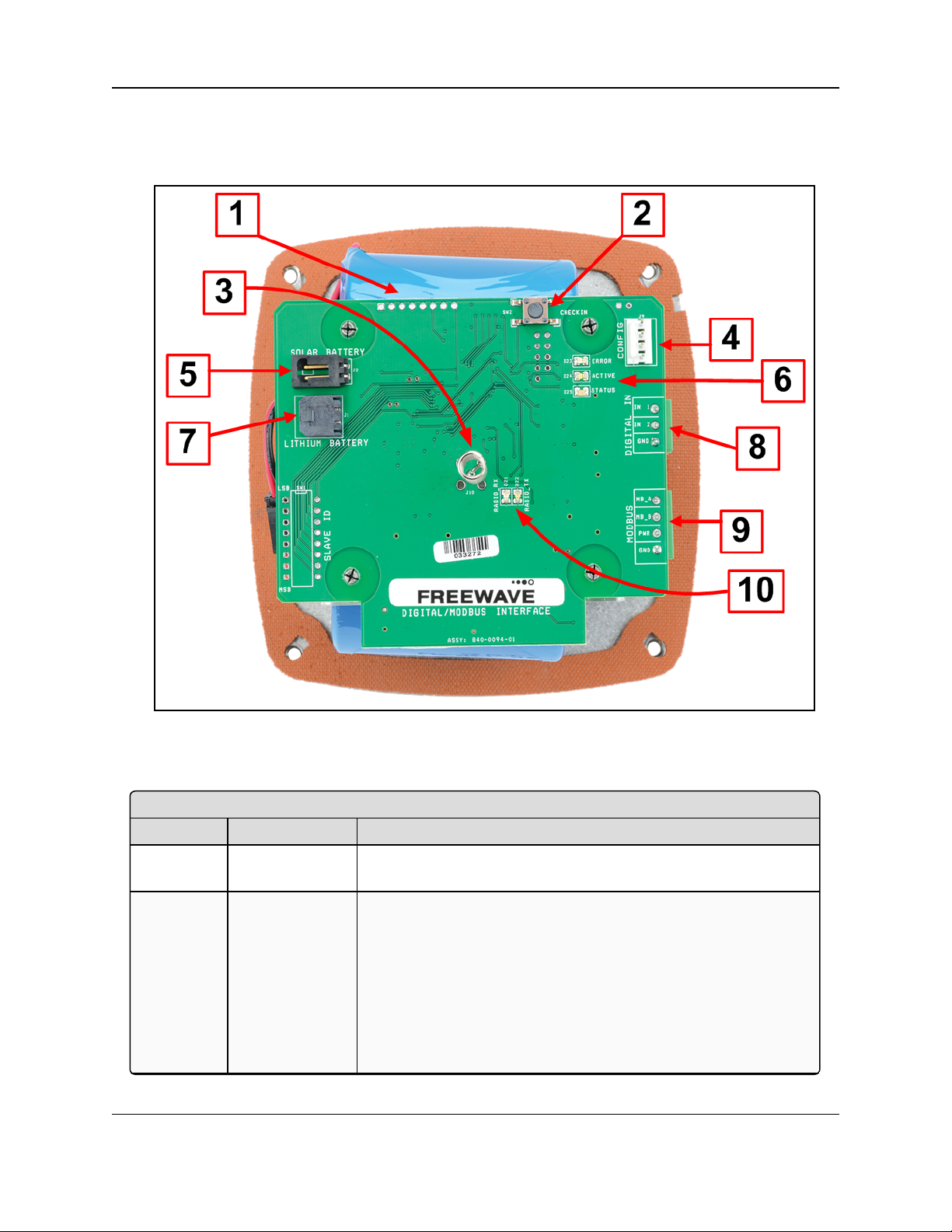
Internal Connections: WC20i-485-2DI or WC20i-485-2DI-S Modular Endpoint
Location # Title Description
1 Internal Lithium
Battery Pack
This is the location of the Internal Lithium Battery Pack.
2 Check-in button On the WC20i, press the Check-in button to apply power to the
configured sensor, read the sensor values, and send the collected
sensor data to the Gateway.
l When the sensor is detected, the Status LED blinks once and
its data is read.
l See LEDs (on page 93) for detailed information.
l The WC20i sends the collected sensor data to the WC45i-
Gateway.
3.1. Internal Connections
These are the internal connections for the WC20i-485-2DI or WC20i-485-2DI-S Modular
Endpoint:
Figure 1: Internal Connections: WC20i-485-2DI or WC20i-485-2DI-S Modular
Endpoint
LUM0096AA Rev Apr-2018 Page 12 of 100 Copyright © 2018FreeWave
This document is the property of FreeWave Technologies, Inc. and contains proprietary information owned by
FreeWave. This document cannot be reproduced in whole or in part by any means without written permission from
FreeWave Technologies, Inc.
Page 13

WC20i Modular Endpoints - 485-2DI Modbus: User - Reference Manual
Internal Connections: WC20i-485-2DI or WC20i-485-2DI-S Modular Endpoint
Location # Title Description
3 Internal Antenna The Internal Antenna communicates with the WC45i-Gateway.
4 Config / Debug
connector
This is the connection for the 4-pin to USB programming cable
(FreeWave Part #WC-USB-4PIN).
Note: Debug and configuration information is available
through WC Toolkit if a connection is made using the
RS232 Config / Debug connector and the WC-USB-4PIN
cable.
5 Solar Battery
connection
This is the connection for a solar panel or external battery.
6 Status LEDs See LEDs (on page 93) for detailed information.
7 Internal
Lithium Battery
connection
The Internal Lithium Battery connection is the connection for the
internal battery cable.
8 Digital Input
Sensor
connector
This is the connection for the Digital Input sensor.
9 Modbus Sensor
connector
This is the connection for the chosen Modbus sensor.
10 Radio LEDs See LEDs (on page 93) for detailed information.
LUM0096AA Rev Apr-2018 Page 13 of 100 Copyright © 2018FreeWave
This document is the property of FreeWave Technologies, Inc. and contains proprietary information owned by
FreeWave. This document cannot be reproduced in whole or in part by any means without written permission from
FreeWave Technologies, Inc.
Page 14

3. WC20i-485-2DI or WC20-485-2DI-S Connections
3.2. Power Connection
Important!: Verify the items listed in Equipment (on page 9) are available before starting this
procedure.
It is assumed that the reader and installer have completed the FreeWave WC20i installation and
setup training to follow the procedures in this document.
Power is supplied using either a:
l Battery Connection (on page 15)
l Solar Panel Connection (on page 16)
LUM0096AA Rev Apr-2018 Page 14 of 100 Copyright © 2018FreeWave
This document is the property of FreeWave Technologies, Inc. and contains proprietary information owned by
FreeWave. This document cannot be reproduced in whole or in part by any means without written permission from
FreeWave Technologies, Inc.
Page 15
WC20i Modular Endpoints - 485-2DI Modbus: User - Reference Manual
3.2.1. Battery Connection
Note: See Internal Lithium Battery Replacement (on page 62) to replace the battery.
1. All wiring should be neat and orderly.
2. Using the Philips screwdriver, remove the four screws holding down the WC20i cover and
remove the cover.
Use the WC20i cover to hold the four screws while configuring the WC20i or when
connecting or replacing the battery.
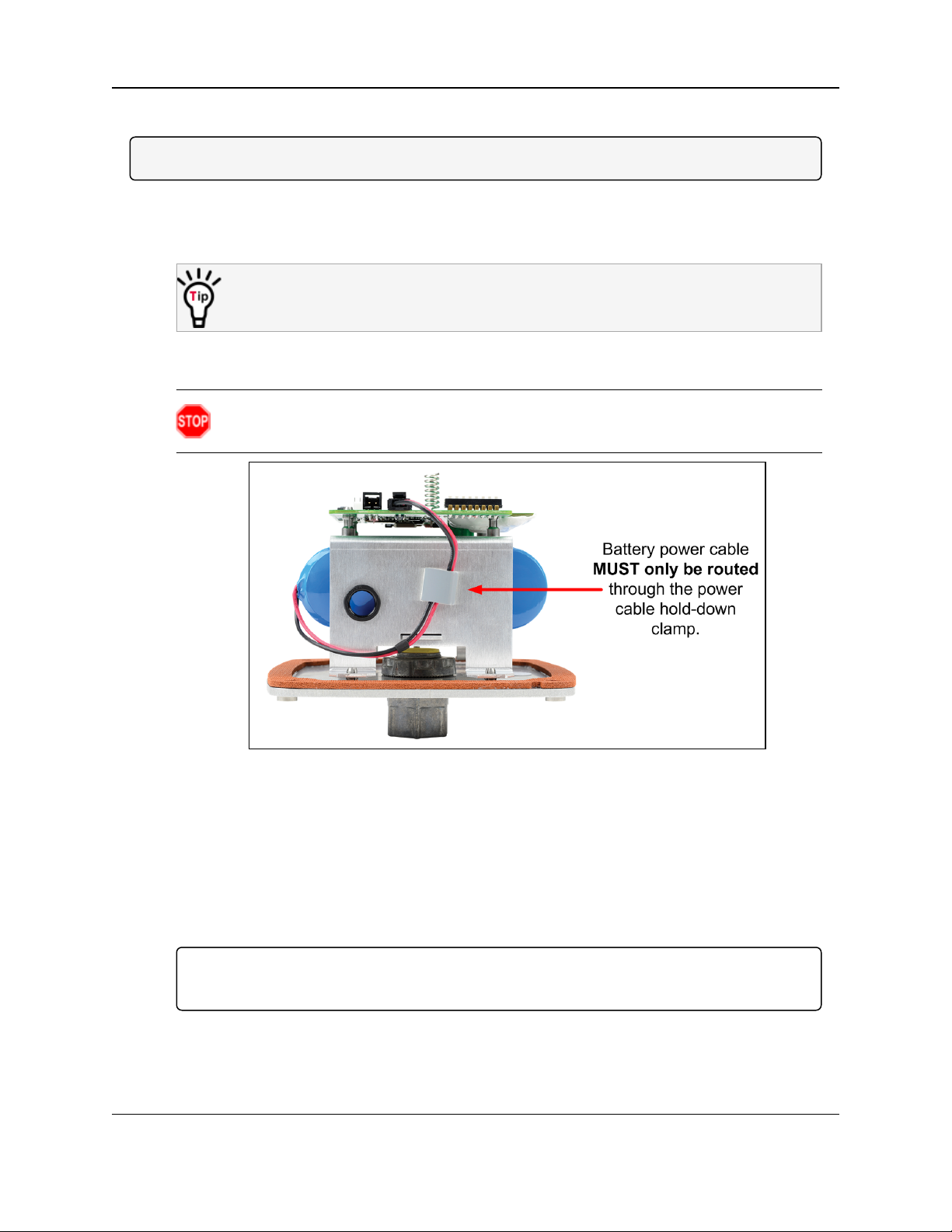
3. Verify the battery power wire is routed through the power cable hold-down clamp.
(Figure 2)
Warning! The battery or solar power cable MUST only be routed through the power
cable hold-down clamp and, as applicable, the solar power cable gland.
Figure 2: Battery Power Cable through the Power Cable Hold-down Clamp
4. Connect the battery power cable to the Internal Lithium Battery connection (see #7 of
Figure 1 on page 12).
5. Connect the 4-pin to USB programming cable to the RS232 Config / Debug connector
(see #4 of Figure 1 on page 12).
6. Connect the USB end of the 4-pin to USB programming cable to the computer.
7. If this is the first time the WC20i is installed, wait for the drivers to install.
Important!: Depending on the computer and connection, the driver installation can take 3-6
minutes.
8. Continue with Sensor Connection - WC20i-485-2DI / WC20i-485-2DI-S (on page 17).
LUM0096AA Rev Apr-2018 Page 15 of 100 Copyright © 2018FreeWave
This document is the property of FreeWave Technologies, Inc. and contains proprietary information owned by
FreeWave. This document cannot be reproduced in whole or in part by any means without written permission from
FreeWave Technologies, Inc.
Page 16
3. WC20i-485-2DI or WC20-485-2DI-S Connections
3.2.2. Solar Panel Connection
1. All wiring should be neat and orderly.
2. Using the Philips screwdriver, remove the four screws holding down the WC20i cover and
remove the cover.
Use the WC20i cover to hold the four screws while configuring the WC20i or when
connecting or replacing the battery.
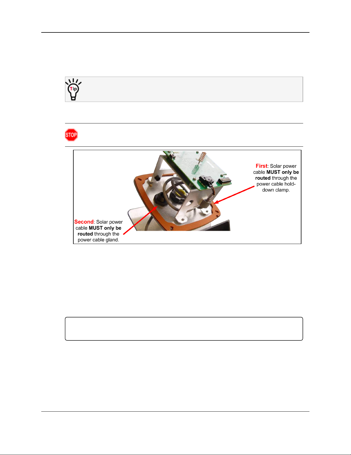
3. Verify the solar power cable is routed through the power cable hold-down clamp and the
power cable gland. (Figure 3)
Warning! The battery or solar power cable MUST only be routed through the power
cable hold-down clamp and, as applicable, the solar power cable gland.
Figure 3: Solar Power Cable through the Power Cable Hold-down Clamp
4. Connect the solar power cable to the Solar Battery connection (see #5 of Figure 1 on
page 12).
5. Connect the 4-pin to USB programming cable to the RS232 Config / Debug connector
(see #4 of Figure 1 on page 12).
6. Connect the USB end of the 4-pin to USB programming cable to the computer.
7. If this is the first time the WC20i is installed, wait for the drivers to install.
Important!: Depending on the computer and connection, the driver installation can take 3-6
minutes.
8. Continue with Sensor Connection - WC20i-485-2DI / WC20i-485-2DI-S (on page 17).
LUM0096AA Rev Apr-2018 Page 16 of 100 Copyright © 2018FreeWave
This document is the property of FreeWave Technologies, Inc. and contains proprietary information owned by
FreeWave. This document cannot be reproduced in whole or in part by any means without written permission from
FreeWave Technologies, Inc.
Page 17
WC20i Modular Endpoints - 485-2DI Modbus: User - Reference Manual
3.3. Sensor Connection - WC20i-485-2DI / WC20i-485-2DI-S
l Digital Sensor Connection (on page 17)
l Modbus Sensor Connection (on page 18)
3.3.1. Digital Sensor Connection
1. Use these examples to connect the Digital Input sensors:
l Dry Contact Connection (on page 20)
l Open Collector Connection (on page 21)
l Voltage Pulse Connection (on page 22)
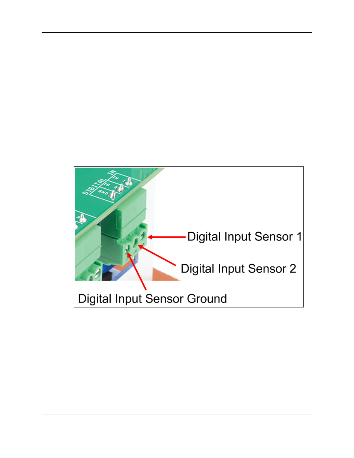
2. Connect the sensor terminals: (Figure 4)
a. Connect the sensor terminal to the Digital Input Sensor 1 (IN 1).
b. Optional: Connect the sensor terminal to the Digital Input Sensor 2 (IN 2).
c. Connect the sensor ground terminal to the Digital Input Sensor Ground (GND).
Figure 4: WC20i-485-2DI Digital Input 1 and 2 and GND (ground) Sensor
Connection
3. When the connection is made, continue with Sensor Cable Routing on the WC20i (on page
23).
LUM0096AA Rev Apr-2018 Page 17 of 100 Copyright © 2018FreeWave
This document is the property of FreeWave Technologies, Inc. and contains proprietary information owned by
FreeWave. This document cannot be reproduced in whole or in part by any means without written permission from
FreeWave Technologies, Inc.
Page 18

3. WC20i-485-2DI or WC20-485-2DI-S Connections
3.3.2. Modbus Sensor Connection
1. Connect the sensor terminals: (Figure 5)
a. The positive Modbus terminal of the sensor is connected to the Modbus A (+)
terminal on the WC20i Endpoint.
b. The negative Modbus terminal is connected to the Modbus B (-) terminal of the
WC20i Endpoint.
c. The power Modbus terminal is connected to the PWR terminal of the WC20i Endpoint.
d. The ground Modbus terminal is connected to the GND terminal of the WC20i
Endpoint.
Figure 5: MB_A+ (positive), MB_B- (negative), PWR (power), and GND
(ground) Sensor Connection
2. When the connection is made, continue with Sensor Cable Routing on the WC20i (on page
23).
LUM0096AA Rev Apr-2018 Page 18 of 100 Copyright © 2018FreeWave
This document is the property of FreeWave Technologies, Inc. and contains proprietary information owned by
FreeWave. This document cannot be reproduced in whole or in part by any means without written permission from
FreeWave Technologies, Inc.
Page 19

WC20i Modular Endpoints - 485-2DI Modbus: User - Reference Manual
3.4. Sensor Connection
The WC20i-485-2DI has two digital input channels:
l DN1
l DN2
l Each counter input may be:
l a Dry Contact Connection (on page 20).
l an Open Collector Connection (on page 21) (sinking ground).
l a Voltage Pulse Connection (on page 22).
l The inputs can count up to 2000 Hz.
l The digital outputs are connected to the WC20i-DI board as shown in Figure 6, Figure 7,
or Figure 8.
The counts accumulate with the current counts are stored into non-volatile memory every two
hours.
l If the system is reset, the counts revert to the last stored value from non-volatile memory.
l The system reports the state of the contact closure input (open or closed) at the time of
check-in.
LUM0096AA Rev Apr-2018 Page 19 of 100 Copyright © 2018FreeWave
This document is the property of FreeWave Technologies, Inc. and contains proprietary information owned by
FreeWave. This document cannot be reproduced in whole or in part by any means without written permission from
FreeWave Technologies, Inc.
Page 20
3. WC20i-485-2DI or WC20-485-2DI-S Connections
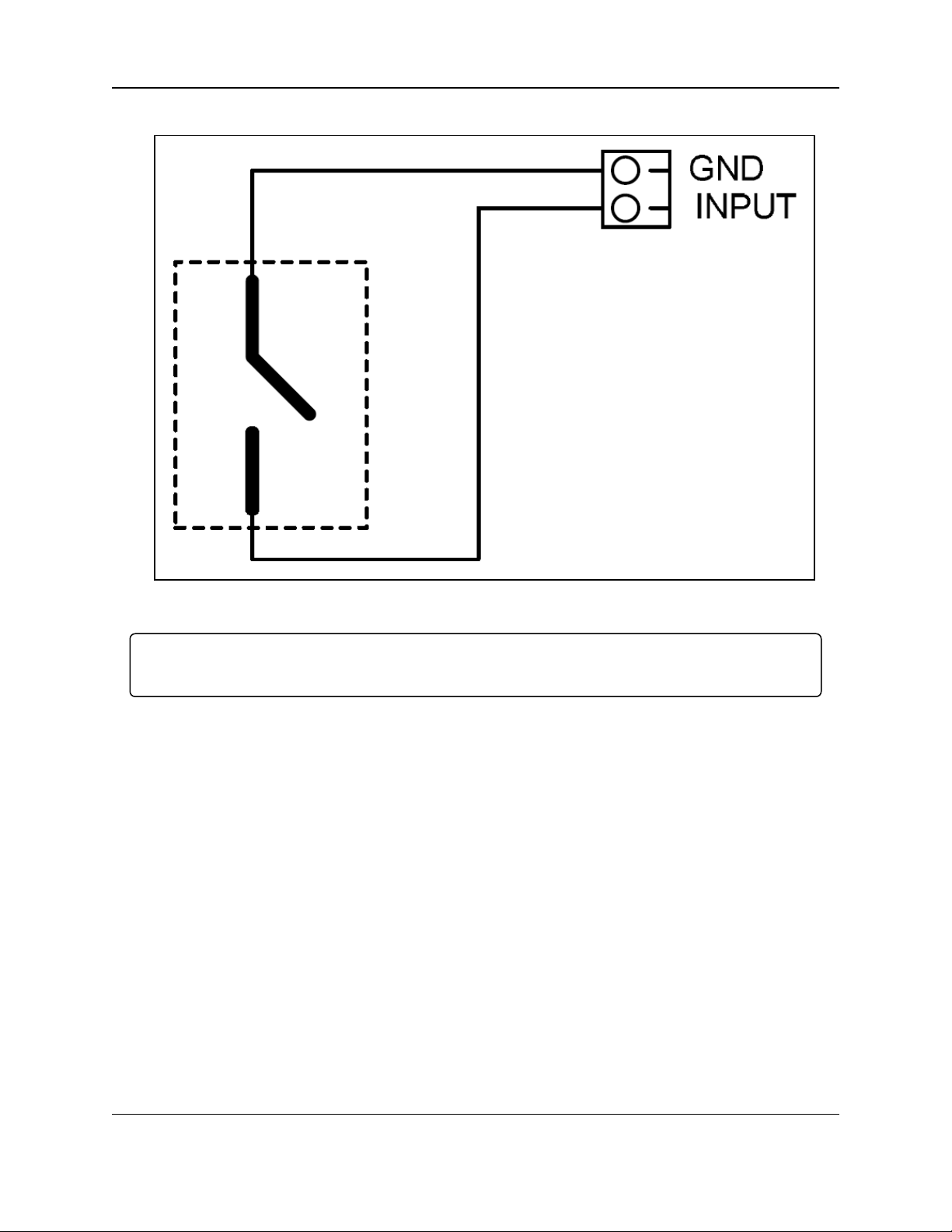
3.4.1. Dry Contact Connection
Figure 6: Dry Contact Connection
Important!: When the connection is made, continue with Sensor Cable Routing on the WC20i (on
page 23).
LUM0096AA Rev Apr-2018 Page 20 of 100 Copyright © 2018FreeWave
This document is the property of FreeWave Technologies, Inc. and contains proprietary information owned by
FreeWave. This document cannot be reproduced in whole or in part by any means without written permission from
FreeWave Technologies, Inc.
Page 21
WC20i Modular Endpoints - 485-2DI Modbus: User - Reference Manual
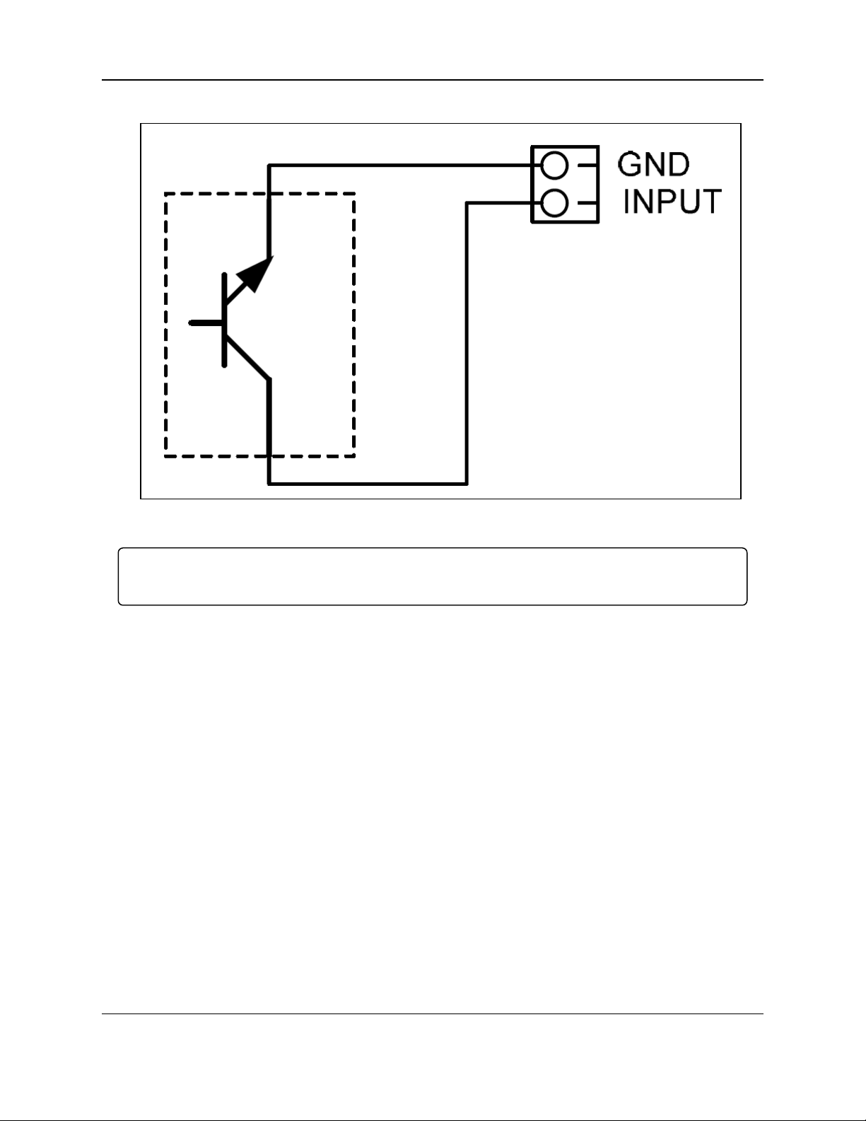
3.4.2. Open Collector Connection
Figure 7: Open Collector Connection
Important!: When the connection is made, continue with Sensor Cable Routing on the WC20i (on
page 23).
LUM0096AA Rev Apr-2018 Page 21 of 100 Copyright © 2018FreeWave
This document is the property of FreeWave Technologies, Inc. and contains proprietary information owned by
FreeWave. This document cannot be reproduced in whole or in part by any means without written permission from
FreeWave Technologies, Inc.
Page 22
3. WC20i-485-2DI or WC20-485-2DI-S Connections
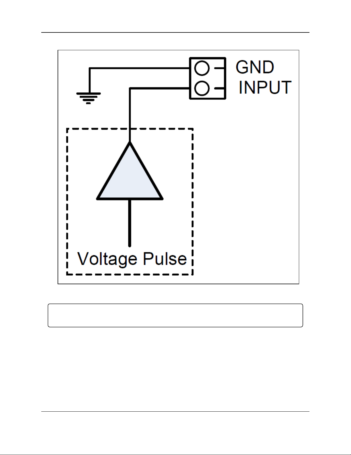
3.4.3. Voltage Pulse Connection
Figure 8: Voltage Pulse Connection
Important!: When the connection is made, continue with Sensor Cable Routing on the WC20i (on
page 23).
LUM0096AA Rev Apr-2018 Page 22 of 100 Copyright © 2018FreeWave
This document is the property of FreeWave Technologies, Inc. and contains proprietary information owned by
FreeWave. This document cannot be reproduced in whole or in part by any means without written permission from
FreeWave Technologies, Inc.
Page 23
WC20i Modular Endpoints - 485-2DI Modbus: User - Reference Manual
3.5. Sensor Cable Routing on the WC20i
Note: Many sensors are compatible with the FreeWave WC20i-485-2DI or WC20i-485-2DI-S
Modular Endpoint.
See www.freewave.com for the most up-to-date list of these sensors.
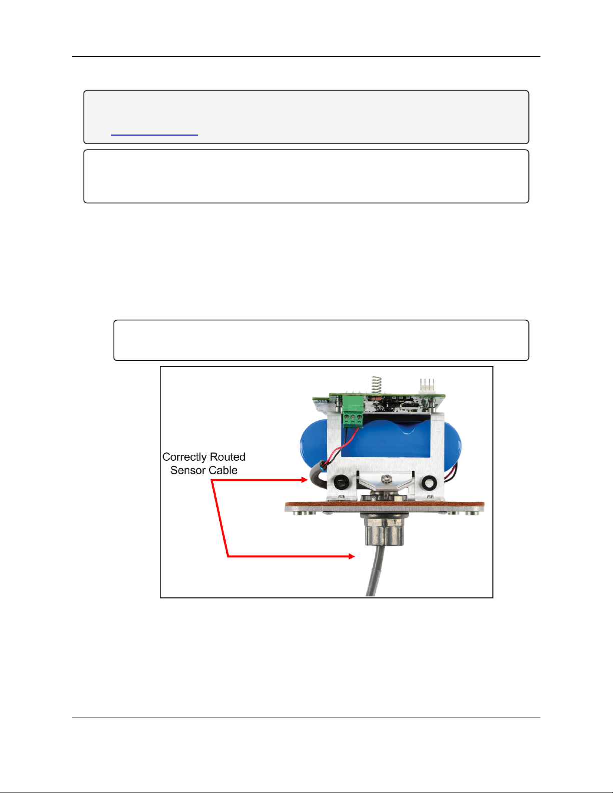
Important!: To ensure intrinsic safety is maintained, the installer is required to follow these
procedures when connecting sensors to a WAVECONTACT Endpoint.
See Figure 9 for the proper cable routing.
Procedure
1. All wiring should be neat and orderly.
2. Verify the battery power wire is routed through the power cable hold-down clamp.
(Figure 2)
See Battery Connection (on page 15).
3. Strip the cable wires to the sensor so that there is minimal exposed un-insulated wire when
inserted into the screw terminal.
Important!: For both the battery powered and solar powered WC20i, sensor wires entering
the enclosure MUST be routed and connected as shown in Figure 9.
Figure 9: Correctly Routed Sensor Cable
4. Continue with either:
l WC Toolkit Installation (on page 24)
l Configuration (on page 34).
LUM0096AA Rev Apr-2018 Page 23 of 100 Copyright © 2018FreeWave
This document is the property of FreeWave Technologies, Inc. and contains proprietary information owned by
FreeWave. This document cannot be reproduced in whole or in part by any means without written permission from
FreeWave Technologies, Inc.
Page 24
WC20i Modular Endpoints - 485-2DI Modbus: User - Reference Manual
4. WC Toolkit Installation
Note: The images in this procedure are for Windows® 7 and/or Firefox®.
The dialog boxes and windows may appear differently on each computer.
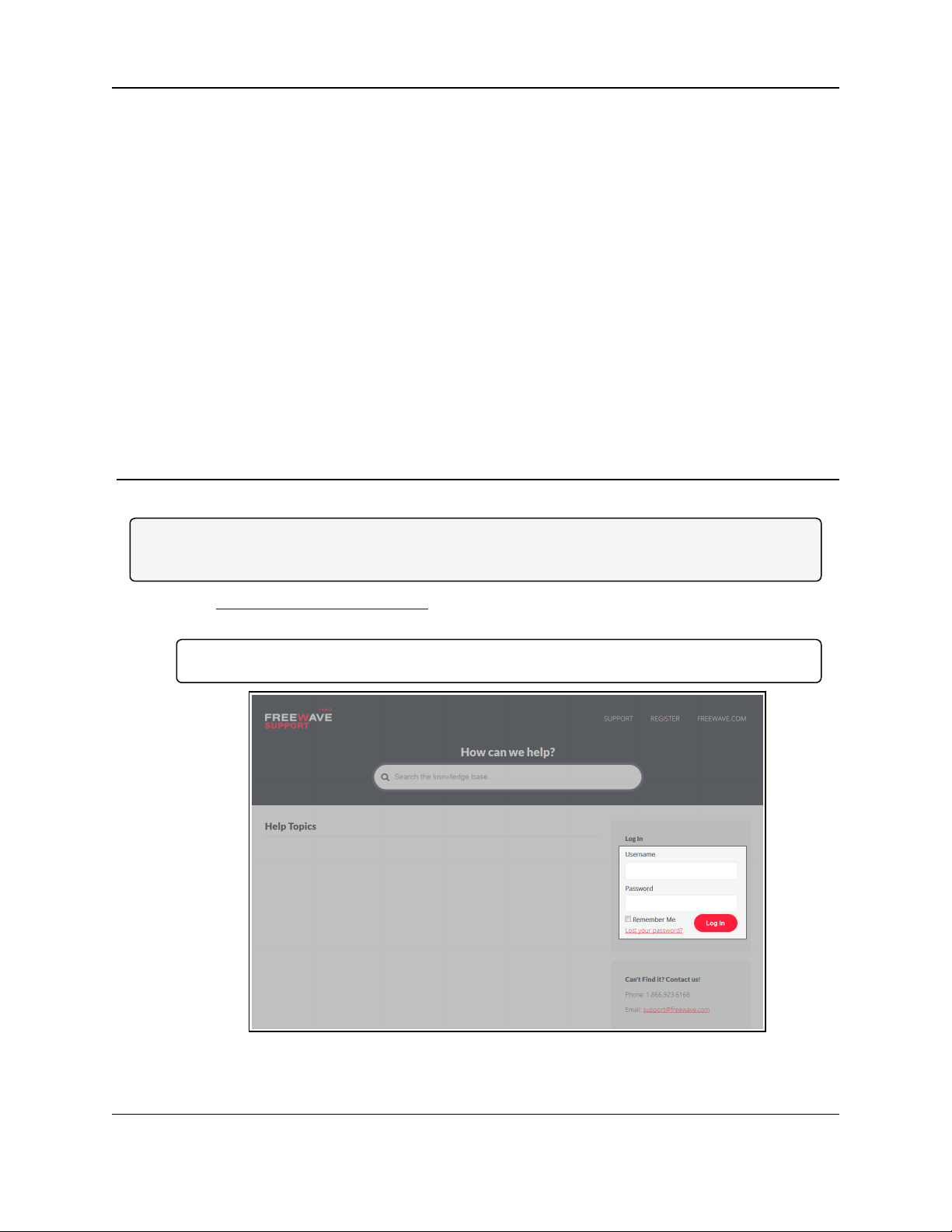
1. Click http://support.freewave.com/.
The FreeWave Support site opens.
Important!: Registration is required to use this website.
Figure 10: FreeWave Login window
2. Enter the User Name and Password.
LUM0096AA Rev Apr-2018 Page 24 of 100 Copyright © 2018FreeWave
This document is the property of FreeWave Technologies, Inc. and contains proprietary information owned by
FreeWave. This document cannot be reproduced in whole or in part by any means without written permission from
FreeWave Technologies, Inc.
Page 25
4. WC Toolkit Installation
3.
Click .
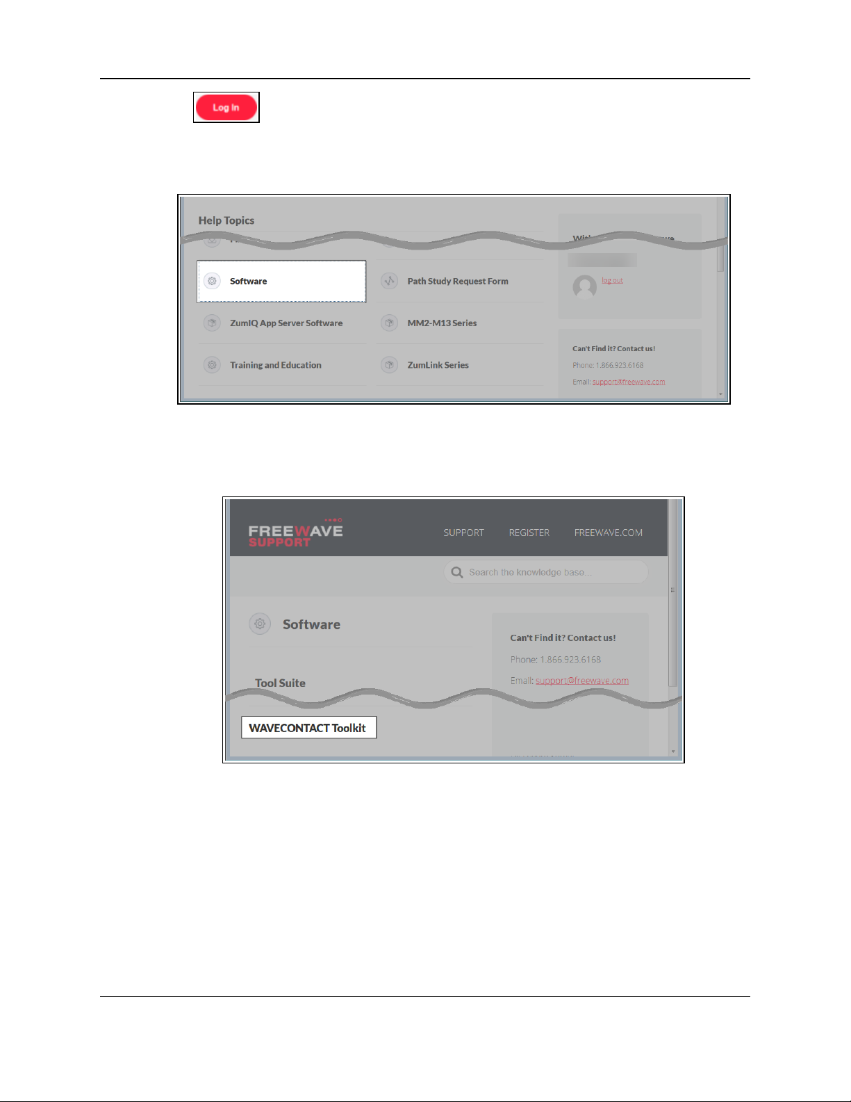
A successful Login message briefly appears.
The Help Topics window opens.
4. Click the Software link.
Figure 11: Help Topics window
The Software window opens.
5. Click the WAVECONTACT Toolkit link.
Figure 12: Software window
The available software appears in the window.
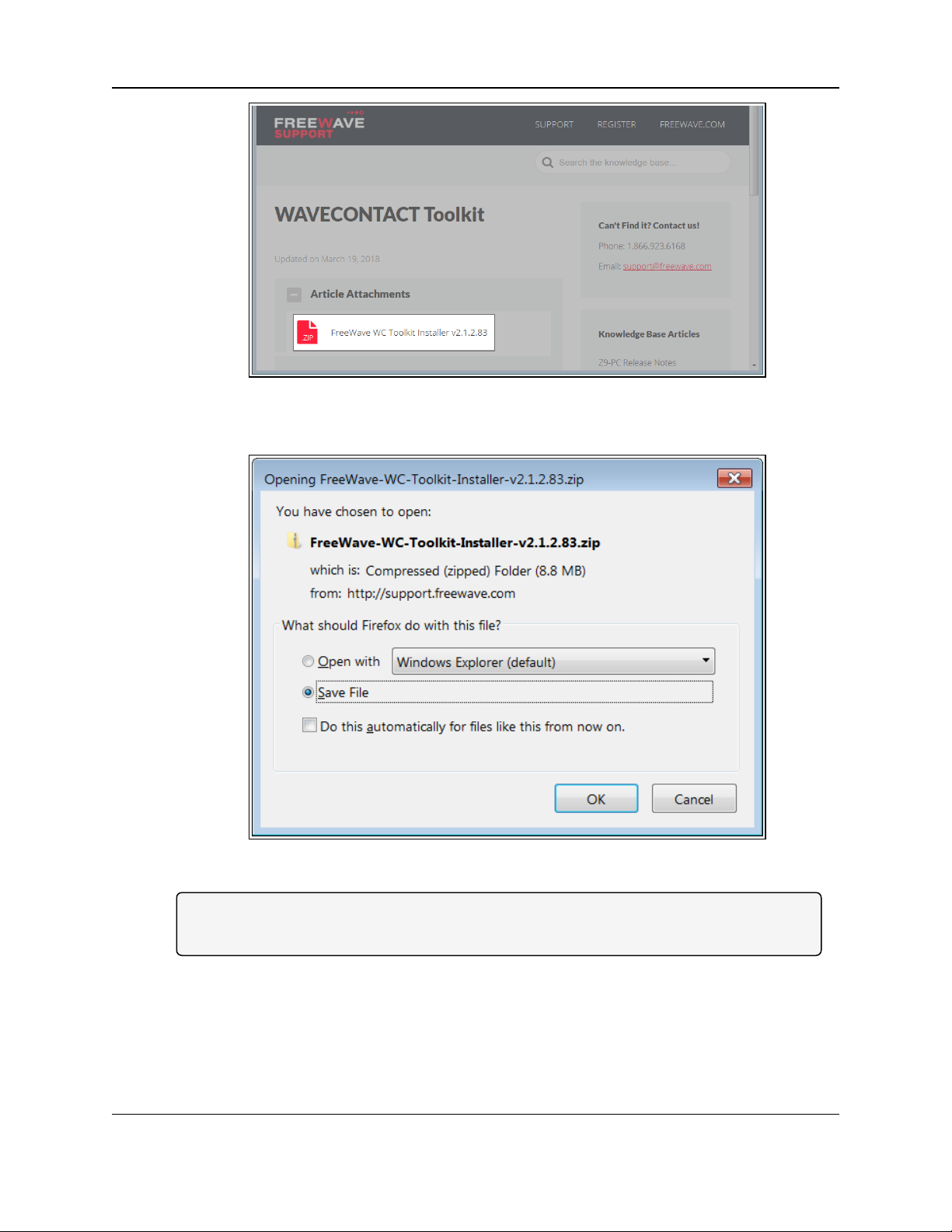
6. Select and click the attachment.
LUM0096AA Rev Apr-2018 Page 25 of 100 Copyright © 2018FreeWave
This document is the property of FreeWave Technologies, Inc. and contains proprietary information owned by
FreeWave. This document cannot be reproduced in whole or in part by any means without written permission from
FreeWave Technologies, Inc.
Page 26
WC20i Modular Endpoints - 485-2DI Modbus: User - Reference Manual
Figure 13: WAVECONTACT Toolkit window
The Opening dialog box opens.
Figure 14: WC Toolkit Opening dialog box
Note: This procedure shows Firefox® dialog boxes.
Other browsers will have different dialog boxes and procedures.
7. Click OK.
The Enter name of file to save to dialog box opens.
LUM0096AA Rev Apr-2018 Page 26 of 100 Copyright © 2018FreeWave
This document is the property of FreeWave Technologies, Inc. and contains proprietary information owned by
FreeWave. This document cannot be reproduced in whole or in part by any means without written permission from
FreeWave Technologies, Inc.
Page 27
4. WC Toolkit Installation
Figure 15: Enter name of file to save to dialog box
8. Search for and select a location to save the .zip file to and click Save.
The Enter name of file to save to dialog box closes.
9. Open a Windows® Explorer window and find the location where the .zip file was saved.
10. Double-click the .zip file.
11. Extract the .exe file from the .zip file into a parent location.
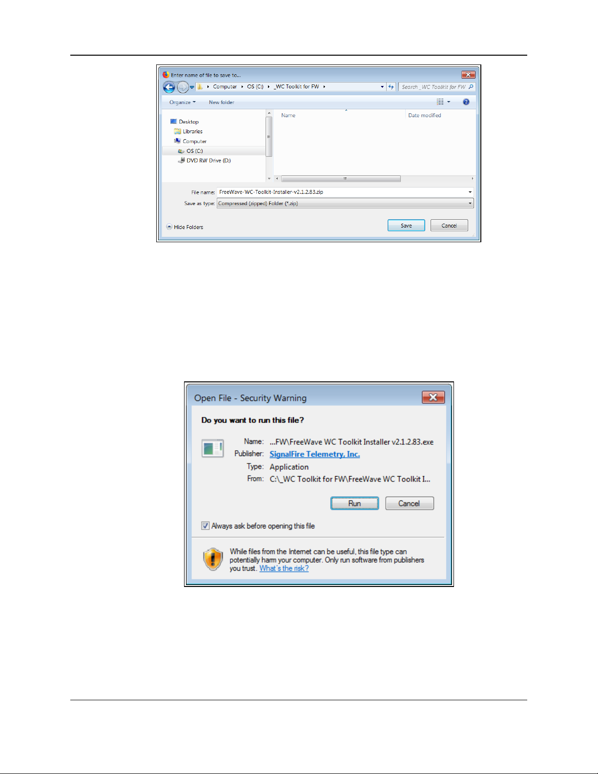
12. Double-click the .exe file to run the WC Toolkit installer.
The Open File - Security Warning dialog box opens.
Figure 16: Open File - Security Warning dialog box
13. Click Run.
The User Account Control dialog box opens.
LUM0096AA Rev Apr-2018 Page 27 of 100 Copyright © 2018FreeWave
This document is the property of FreeWave Technologies, Inc. and contains proprietary information owned by
FreeWave. This document cannot be reproduced in whole or in part by any means without written permission from
FreeWave Technologies, Inc.
Page 28
WC20i Modular Endpoints - 485-2DI Modbus: User - Reference Manual
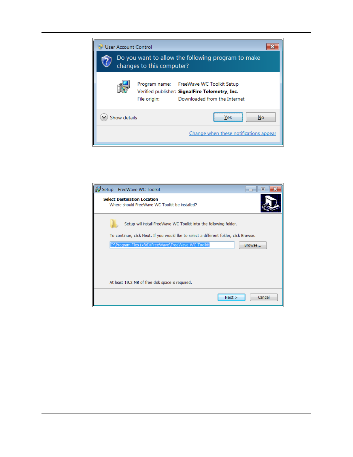
Figure 17: User Account Control dialog box
14. Click Yes.
The WC Toolkit Setup Wizard starts.
Figure 18: WC Toolkit Setup Wizard - Select Destination Location window
15. Click Next to continue.
The Ready to Install window opens.
LUM0096AA Rev Apr-2018 Page 28 of 100 Copyright © 2018FreeWave
This document is the property of FreeWave Technologies, Inc. and contains proprietary information owned by
FreeWave. This document cannot be reproduced in whole or in part by any means without written permission from
FreeWave Technologies, Inc.
Page 29

4. WC Toolkit Installation
Figure 19: WC Toolkit Setup Wizard - Ready to Install window
16. Click Install.
The install process is very quick.
The Installation Complete window opens.
Figure 20: WC Toolkit Setup Wizard - Installation Complete window
17. Click Finish to open WC Toolkit.
An Update message appears in the WC Toolkit window is an update is available.
LUM0096AA Rev Apr-2018 Page 29 of 100 Copyright © 2018FreeWave
This document is the property of FreeWave Technologies, Inc. and contains proprietary information owned by
FreeWave. This document cannot be reproduced in whole or in part by any means without written permission from
FreeWave Technologies, Inc.
Page 30
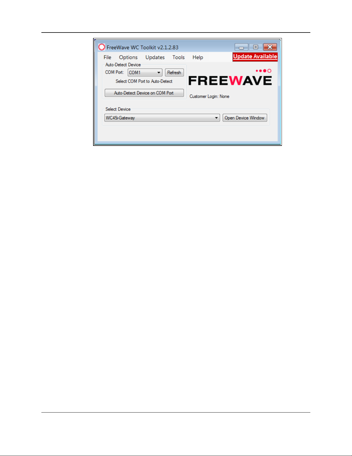
WC20i Modular Endpoints - 485-2DI Modbus: User - Reference Manual
Figure 21: WC Toolkit - Update Available message
18. Continue with the WC Toolkit Update (on page 31) procedure.
LUM0096AA Rev Apr-2018 Page 30 of 100 Copyright © 2018FreeWave
This document is the property of FreeWave Technologies, Inc. and contains proprietary information owned by
FreeWave. This document cannot be reproduced in whole or in part by any means without written permission from
FreeWave Technologies, Inc.
Page 31

WC20i Modular Endpoints - 485-2DI Modbus: User - Reference Manual
5. WC Toolkit Update
If the WAVECONTACT device is connected to the internet, WC Toolkit automatically searches for
an update for either the WC Toolkit itself or the connected device's firmware.
An Update Available message appears if an update is available.
Note: An Update Available message also appears in the Device Configuration window (on page 65)
for any connected WAVECONTACT device when an update is available for that device.
The update procedure is the same for the device and WC Toolkit.
1. Open the WC Toolkit software.
The Update Available message appears in the window. (Figure 22)
Figure 22: WC Toolkit - Update Available message
LUM0096AA Rev Apr-2018 Page 31 of 100 Copyright © 2018FreeWave
This document is the property of FreeWave Technologies, Inc. and contains proprietary information owned by
FreeWave. This document cannot be reproduced in whole or in part by any means without written permission from
FreeWave Technologies, Inc.
Page 32

5. WC Toolkit Update
2. Click the Update Available message link.
Figure 23: Click the Update Available message link
The Open File - Security Warning dialog box opens.
Figure 24: Open File - Security Warning dialog box
3. Click Run.
The User Account Control dialog box opens.
LUM0096AA Rev Apr-2018 Page 32 of 100 Copyright © 2018FreeWave
This document is the property of FreeWave Technologies, Inc. and contains proprietary information owned by
FreeWave. This document cannot be reproduced in whole or in part by any means without written permission from
FreeWave Technologies, Inc.
Page 33

WC20i Modular Endpoints - 485-2DI Modbus: User - Reference Manual
Figure 25: User Account Control dialog box
4. Click Yes.
The WC Toolkit update process is very quick.
When the update is completed, WC Toolkit re-opens the Select Device window showing
the updated software version in the WC Toolkit window. (Figure 26)
Figure 26: Select Device window
5. Continue with Configuration of the WC20i-485-2DI or WC20-485-2DI-S.
LUM0096AA Rev Apr-2018 Page 33 of 100 Copyright © 2018FreeWave
This document is the property of FreeWave Technologies, Inc. and contains proprietary information owned by
FreeWave. This document cannot be reproduced in whole or in part by any means without written permission from
FreeWave Technologies, Inc.
Page 34

WC20i Modular Endpoints - 485-2DI Modbus: User - Reference Manual
6. Configuration
Note: The terms node and Endpoint are used interchangeably in this document.
FREEWAVE Recommends: Install and configure the WC45i Gateway before any Endpoints to
ensure the Endpoints have connectivity after installation.
Warning! Perform the Configuration steps in a safe location only.
AVERTISSEMENT: Suivez les étapes de cette section (Configuration) dans un endroit sûr
uniquement.
The Endpoints MUST BE set up for correct operation before they are placed in the field.
Configurable items include:
l Check-in period selection
l Modbus Slave ID setting
l Modbus registers to be polled
l Modbus sensor power on time
l Network selection
l Network Group selection
l Optional: Node Name
l Radio Mode selection
Note: The is configured using the WC Toolkit.
Download the WC Toolkit software from http://support.freewave.com/.
Registration is required to use this website.
LUM0096AA Rev Apr-2018 Page 34 of 100 Copyright © 2018FreeWave
This document is the property of FreeWave Technologies, Inc. and contains proprietary information owned by
FreeWave. This document cannot be reproduced in whole or in part by any means without written permission from
FreeWave Technologies, Inc.
Page 35

6. Configuration
Warning! Debug and configuration information is available if the 4-pin to USB programming
cable is connected to the RS232 Config / Debug connector using the debug port on the main
board.
The USB converter cable (FreeWave Part #WC-USB-4PIN) must be used for this interface.
Debug and configuration is done using the WC Toolkit.
Warning! Only connect to the Config / Debug connector port in a safe area!
AVERTISSEMENT: Branchez le port de déboggage que dans une zone secure.
Procedure
Note: The screenshots are examples only.
The dialog boxes and windows appear differently on each computer.
1. Verify the WC Toolkit software is installed on the computer connected to the WC20i.
Note: See WC Toolkit Installation (on page 24) and WC Toolkit Update (on page 31).
2. Verify the Gateway is installed and configured before continuing with the Endpoint
configuration.
3. Connect the WC-USB-4PIN - 4-pin to USB programming cable to the computer and the
WC20i.
4. Open the WC Toolkit software.
The Select Device window opens. (Figure 27)
Figure 27: Select Device window
5. Click the Refresh button to have WC Toolkit search for and list the available COM ports
reported by Windows and connected devices in the COM Port list box.
6. Click the COM Port list box arrow and select the COM port on the computer associated
with the connected WC20i-485-2DI or WC20-485-2DI-S.
7. Click the Auto-Detect Device on COM Port button to have WC Toolkit connect the
device to the COM Port selected in the COM Port list box.
LUM0096AA Rev Apr-2018 Page 35 of 100 Copyright © 2018FreeWave
This document is the property of FreeWave Technologies, Inc. and contains proprietary information owned by
FreeWave. This document cannot be reproduced in whole or in part by any means without written permission from
FreeWave Technologies, Inc.
Page 36

WC20i Modular Endpoints - 485-2DI Modbus: User - Reference Manual
Note: Optional: Click the Select Device list box arrow and select the connected device.
Click the Open Device Window button to open the Device Configuration window (on page
65).
Figure 28: Select Device list box
The Device Configuration window opens for the selected device.
Note: See Device Configuration window (on page 65) for detailed information.
LUM0096AA Rev Apr-2018 Page 36 of 100 Copyright © 2018FreeWave
This document is the property of FreeWave Technologies, Inc. and contains proprietary information owned by
FreeWave. This document cannot be reproduced in whole or in part by any means without written permission from
FreeWave Technologies, Inc.
Page 37

6. Configuration
Figure 29: Device Configuration window:
WC20i-485-2DI or WC20i-485-2DI-S
8. In the Set Encryption Key area (#5), change these settings:
a. In the Key text box, enter the encryption key for the device using 6 to 16 characters.
b. Click the Set button to save the information.
Important!: A Key CANNOT contain spaces or angle brackets.
The Gateway and Endpoints only communicate if they are configured with the same Key.
When setting up a new network, use this same encryption Key on all the devices.
Note: When the WC20i drops its network, it attempts to join networks using the same
encryption Key.
LUM0096AA Rev Apr-2018 Page 37 of 100 Copyright © 2018FreeWave
This document is the property of FreeWave Technologies, Inc. and contains proprietary information owned by
FreeWave. This document cannot be reproduced in whole or in part by any means without written permission from
FreeWave Technologies, Inc.
Page 38

WC20i Modular Endpoints - 485-2DI Modbus: User - Reference Manual
Caution: It is possible to hide the encryption Key so it cannot be read.
This is the most secure option, but if the Key is forgotten, there is no way to recover it.
The Key must be reset on every device on the network.
9. Optional: Click the Settings menu and select Set Encryption Key Unrecoverable to
permanently hide the key.
10. In the Settings area (#6), change these settings:
Note: The Network settings are used to create separate networks using multiple Gateways
(that are in close proximity to one another).
a. Optional: In the Node Name text box, enter a name for the Endpoint using a maximum
of 10 characters.
b. Click the Set button to save the information.
c. Click the Radio Mode list box arrow and select either Sleeping or Non-Sleeping.
Important!: Use Non-Sleeping option ONLY if there is a solar kit attached to the
WC20i. See Included Equipment (on page 10) for additional information.
d. Click the Radio Network list box arrow and select 0 (zero) to 7 for the assigned
number.
e. Click the Radio Network Group list box arrow and select 0 (zero) to 29 for the network
group assigned number.
Important!: The Radio Network and Radio Network Group settings are selected by
the user but MUST MATCH the existing Gateway network for successful communication
between the Gateway and Endpoint.
See WAVECONTACT Network Frequencies (on page 78) for additional information.
f. Click the Set button to save the information.
g. Click the Checkin Interval list box arrow and select how often the Endpoint wakes up,
reads the sensor values , and transmits the data to the Gateway.
h. Click the Set button to save the information.
i. In the Slave ID column / text box, enter the remote source Endpoint Modbus Slave ID.
Important!: Each remote device connected to the Gateway MUST have a unique
Modbus Slave ID (1-240).
Verify there are no duplicate Slave IDs in a given network.
The Gateway only caches one set of data for each Slave ID.
A duplicate is overwritten.
See Remote Modbus Registers (on page 90) for Modbus details.
j. Click the Set button to save the information.
k. In the Sensor On time (sec) text box, enter the number of seconds .
LUM0096AA Rev Apr-2018 Page 38 of 100 Copyright © 2018FreeWave
This document is the property of FreeWave Technologies, Inc. and contains proprietary information owned by
FreeWave. This document cannot be reproduced in whole or in part by any means without written permission from
FreeWave Technologies, Inc.
Page 39

6. Configuration
FREEWAVE Recommends: Accept the default Sensor On time (sec) value of 2
seconds for most devices.
However, radar sensors often require a longer warm-up time.
Note: See the sensor manufacturer’s documentation for more information on warm-up
time for the specific sensor.
l. Optional: Select the Sensor Always On check box to make the sensor always have
power no matter what type of power source is connected to the device.
Caution: Having the Sensor Always On selected is useful for rapid data collection
on a sensor that has a long warm-up time.
However, it will shorten the battery life dramatically unless a Solar Powered
WC20i is used.
m. Click the Set button to save the information.
n. Optional: Click the Sensor Power Mode list box arrow and select either HIGH or LOW
volts for the WC20i.
Note: HIGH outputs 18.5 volts to the sensor and LOW outputs 12.5 volts.
LOW results in longer battery life but some sensors require a higher voltage.
o. Click the Set button to save the information.
p. Click the State Change Checkin list box arrow and select Yes to check on a change of
state at the input rather than waiting for the check in time to expire.
q. Click the Set button to save the information.
11. On the WC20i, press the Check-in button to apply power to the configured sensor, read
the sensor values, and send the collected sensor data to the Gateway.
12. Verify the Gateway is communicating with the Endpoints.
Note: A successful connection on the WAVECONTACT Endpoint is indicated with Green
blinking TX and ACT lights and a Red blinking light for RX.
If the connection is NOT successful, a Green blinking TX light appears for 10 seconds.
13. Continue with:
l Digital Input Debounce (on page 41)
l Digital Input State Latch (on page 43)
l Modbus Program Steps Configuration (on page 44)
14. Close the WC Toolkit software.
15. Remove the WC-USB-4PIN 4-pin to USB programming cable from the computer and the
WC20i.
16. As applicable, replace the Endpoint cover.
17. Install the WC20i using the Direct Mount to Sensor with Short Conduit (on page 61).
LUM0096AA Rev Apr-2018 Page 39 of 100 Copyright © 2018FreeWave
This document is the property of FreeWave Technologies, Inc. and contains proprietary information owned by
FreeWave. This document cannot be reproduced in whole or in part by any means without written permission from
FreeWave Technologies, Inc.
Page 40

WC20i Modular Endpoints - 485-2DI Modbus: User - Reference Manual
18. If this is a WC20i-485-2DI-S installation, follow the tank level manufacturer's installation
procedures for the selected solar mounting kit listed in Available Accessories (on page 94).
LUM0096AA Rev Apr-2018 Page 40 of 100 Copyright © 2018FreeWave
This document is the property of FreeWave Technologies, Inc. and contains proprietary information owned by
FreeWave. This document cannot be reproduced in whole or in part by any means without written permission from
FreeWave Technologies, Inc.
Page 41

6. Configuration
6.1. Digital Input Debounce
Use the Digital Input Debounce window (on page 74) to designate the digital input Debounce
Time to accurately total Digital Input counts.
Note: The Debounce Time is useful when using contacts that may produce extra counts when they
close.
Example: A typical value for a dry contact is 100mS. Any extra counts due to contact bounce within
the Debounce Time setting are ignored.
Procedure
1. Open the Device Configuration window (on page 65).
2. On the Settings menu, click Digital Input Debounce.
Figure 30: Settings menu > Digital Input Debounce
The Digital Input Debounce window opens.
Figure 31: Digital Input Debounce window
3. In the Debounce Time (ms) Input 1 or Input 2 text boxes, enter the time (in mS) during
which possible multiple triggers are treated as a single event.
Note: This is typically used when mechanical contacts are used to generate the input signal.
4. Click the Read Debounce Time button to read the current debounce settings.
This information appears in the Debounce Time (ms) Input 1 or Input 2 text boxes.
5. Click the Write Debounce Time button to save the time entered in the Debounce Time
(ms) Input 1 or Input 2 text boxes to the WC20i.
LUM0096AA Rev Apr-2018 Page 41 of 100 Copyright © 2018FreeWave
This document is the property of FreeWave Technologies, Inc. and contains proprietary information owned by
FreeWave. This document cannot be reproduced in whole or in part by any means without written permission from
FreeWave Technologies, Inc.
Page 42

WC20i Modular Endpoints - 485-2DI Modbus: User - Reference Manual
6. Close the Digital Input Debounce window.
7. Close the WC Toolkit software.
8. Remove the WC-USB-4PIN 4-pin to USB programming cable from the computer and the
WC20i.
9. When the connection is made, continue with Sensor Cable Routing on the WC20i (on page
23).
10. As applicable, replace the Endpoint cover.
11. Install the WC20i using the Direct Mount to Sensor with Short Conduit (on page 61).
12. If this is a WC20i-485-2DI-S installation, follow the tank level manufacturer's installation
procedures for the selected solar mounting kit listed in Available Accessories (on page 94).
LUM0096AA Rev Apr-2018 Page 42 of 100 Copyright © 2018FreeWave
This document is the property of FreeWave Technologies, Inc. and contains proprietary information owned by
FreeWave. This document cannot be reproduced in whole or in part by any means without written permission from
FreeWave Technologies, Inc.
Page 43

6. Configuration
6.2. Digital Input State Latch
The State Latch feature is used where a fast transition sensed by the WC20i-485-2DI may
happen too quickly to be read by the WC45i-Gateway.
The state of one or both of the digital inputs is latched to a value for a configurable number of
seconds.
Example: If the Input Channel 1 list box is set to Latch Closed (1) for the 3 seconds entered in the
Input Channel 1 or 2 Seconds text box, then any close sensed on the digital input is reported as
closed for 3 seconds even in the input opens in less than 3 seconds.
Procedure
1. Open the Device Configuration window (on page 65).
2. On the Settings menu, click State Change Latch Settings.
Figure 32: Settings menu > State Change Latch Settings
The State Change Latch Settings window (on page 76) opens.
Figure 33: State Change Latch Settings window
3. Click the Read State Latch Settings button to read the current state of the latch settings.
4. Click the Input Channel 1 or Input Channel 2list box arrow and select either Latch Open
(0) or Latch Closed (1).
5. In the Input Channel 1 or Input Channel 2 Seconds text boxes, enter the number of
seconds the latch remains open or closed.
6. Click the Write State Latch Settings button to write (save) the changed latch settings.
7. Close the State Change Latch Settings window.
LUM0096AA Rev Apr-2018 Page 43 of 100 Copyright © 2018FreeWave
This document is the property of FreeWave Technologies, Inc. and contains proprietary information owned by
FreeWave. This document cannot be reproduced in whole or in part by any means without written permission from
FreeWave Technologies, Inc.
Page 44

WC20i Modular Endpoints - 485-2DI Modbus: User - Reference Manual
7. Modbus Program Steps Configuration
Important!: The register set to poll on each check-in must be defined using the Current Program
Steps area (on page 71) area of the Device Configuration window.
A program step consists of one of these Modbus operation codes:
l 0x01 for MODBUS_READ_COIL (limit: 1 coil)
l 0x02 MODBUS_READ_INPUT (limit: 1 input)
l 0x03 for MODBUS_READ_HOLDING_REGISTERS
l 0x04 for MODBUS_READ_INPUT_REGISTERS
l 0x05 for MODBUS_WRITE_SINGLE_COIL
Note: A maximum of 34 program steps can be programmed.
Any response from a Modbus device (data or exception) is forwarded to the Modbus Gateway and
cached.
Important!: Each remote device connected to the Gateway MUST have a unique Modbus Slave ID
(1-240).
Verify there are no duplicate Slave IDs in a given network.
The Gateway only caches one set of data for each Slave ID.
A duplicate is overwritten.
See Remote Modbus Registers (on page 90) for Modbus details.
Note: The Slave ID is set in the Configuration (on page 34) procedure.
LUM0096AA Rev Apr-2018 Page 44 of 100 Copyright © 2018FreeWave
This document is the property of FreeWave Technologies, Inc. and contains proprietary information owned by
FreeWave. This document cannot be reproduced in whole or in part by any means without written permission from
FreeWave Technologies, Inc.
Page 45

7. Modbus Program Steps Configuration
Procedure
1. Open the Device Configuration window (on page 65).
Figure 34: Device Configuration window:
WC20i-485-2DI or WC20i-485-2DI-S
2. In the Current Program Steps area (# 7):
a. Click the Read Current Program Steps from Device button to view the current
Program Steps in the table.
b. Optional: Click the Baud Rate list box arrow and select the baud rate for the RS485
Modbus port.
c. Optional: Click the UART Mode list box arrow and select the number of data bits,
parity, and stop bits used with the RS485 Modbus port.
d. Optional: Click the Command Timeout (ms) list box arrow and select the number of
mS the device waits for a response from the attached Modbus device before it times out
the request.
LUM0096AA Rev Apr-2018 Page 45 of 100 Copyright © 2018FreeWave
This document is the property of FreeWave Technologies, Inc. and contains proprietary information owned by
FreeWave. This document cannot be reproduced in whole or in part by any means without written permission from
FreeWave Technologies, Inc.
Page 46

WC20i Modular Endpoints - 485-2DI Modbus: User - Reference Manual
e. Optional: Click the Command Pause (ms) list box arrow and select the number of mS
the device pauses between each Modbus transaction.
f. Optional: Complete any of these procedures:
l Create Program Steps (on page 47)
l Change the Address of Program Steps (on page 50)
l Delete Program Steps (on page 53)
l Re-order Program Steps (on page 57)
3. Click the Write New Program Steps to Device button to save the changes to the WC20i
every time the Program Steps are changed.
4. Click the Run Modbus Program Steps button to run the Program Steps to poll the
Modbus device on each check-in.
5. On the WC20i, press the Check-in button to apply power to the configured sensor, read
the sensor values, and send the collected sensor data to the Gateway.
6. Verify the Gateway is communicating with the Endpoints.
Note: A successful connection on the WAVECONTACT Endpoint is indicated with Green
blinking TX and ACT lights and a Red blinking light for RX.
If the connection is NOT successful, a Green blinking TX light appears for 10 seconds.
FREEWAVE Recommends: Install and configure the WC45i Gateway before any
Endpoints to ensure the Endpoints have connectivity after installation.
7. Close the WC Toolkit software.
8. Remove the WC-USB-4PIN 4-pin to USB programming cable from the computer and the
WC20i.
9. As applicable, replace the Endpoint cover.
10. Install the WC20i using the Direct Mount to Sensor with Short Conduit (on page 61).
11. If this is a WC20i-485-2DI-S installation, follow the tank level manufacturer's installation
procedures for the selected solar mounting kit listed in Available Accessories (on page 94).
LUM0096AA Rev Apr-2018 Page 46 of 100 Copyright © 2018FreeWave
This document is the property of FreeWave Technologies, Inc. and contains proprietary information owned by
FreeWave. This document cannot be reproduced in whole or in part by any means without written permission from
FreeWave Technologies, Inc.
Page 47

7. Modbus Program Steps Configuration
7.1. Create Program Steps
Note: A maximum of 34 program steps can be programmed.
Any response from a Modbus device (data or exception) is forwarded to the Modbus Gateway and
cached.
Procedure
1. Click the Function Code list box arrow and select the operation code for the step.
The options are:
l 0x01 for MODBUS_READ_COIL (limit: 1 coil)
l 0x02 MODBUS_READ_INPUT (limit: 1 input)
l 0x03 for MODBUS_READ_HOLDING_REGISTERS
l 0x04 for MODBUS_READ_INPUT_REGISTERS
l 0x05 for MODBUS_WRITE_SINGLE_COIL
2. In the Address text box, enter the Modbus Register Address of the connected Modbus
device.
3. Depending on the Function Code list box selection, complete one of these steps:
l In the Reg Count text box, enter the number of consecutive Modbus blocks to read or
write.
Note: The Reg Count text box is only available if 0x03 or 0x04 is selected in the
Function Code list box.
l In the Coil Value text box, enter corresponding coil ID number of the connected
Modbus device.
Note: The Coil Value text box is only available if 0x05 is selected in the Function Code
list box.
4. Optional: Click the Register Size list box arrow and select the designated register size in
bits.
The Device Configuration window is similar to Figure 35.
LUM0096AA Rev Apr-2018 Page 47 of 100 Copyright © 2018FreeWave
This document is the property of FreeWave Technologies, Inc. and contains proprietary information owned by
FreeWave. This document cannot be reproduced in whole or in part by any means without written permission from
FreeWave Technologies, Inc.
Page 48

WC20i Modular Endpoints - 485-2DI Modbus: User - Reference Manual
Figure 35: Example: WC20i-485-2DI Device Configuration window with
Program Steps
5. Click the Add New Program Step button to add a new Program Step to the table.
Note: If the step is valid, it is added to the Registers table in the next available slot.
Use the Re-order Program Steps (on page 57) procedure to change the order of the
program steps in the table.
6. Click the Write New Program Steps to Device button to save the changes to the WC20i
every time the Program Steps are changed.
LUM0096AA Rev Apr-2018 Page 48 of 100 Copyright © 2018FreeWave
This document is the property of FreeWave Technologies, Inc. and contains proprietary information owned by
FreeWave. This document cannot be reproduced in whole or in part by any means without written permission from
FreeWave Technologies, Inc.
Page 49

7. Modbus Program Steps Configuration
7. Click the Run Modbus Program Steps button to run the Program Steps to poll the
Modbus device on each check-in.
8. On the WC20i, press the Check-in button to apply power to the configured sensor, read
the sensor values, and send the collected sensor data to the Gateway.
9. Verify the Gateway is communicating with the Endpoints.
Note: A successful connection on the WAVECONTACT Endpoint is indicated with Green
blinking TX and ACT lights and a Red blinking light for RX.
If the connection is NOT successful, a Green blinking TX light appears for 10 seconds.
FREEWAVE Recommends: Install and configure the WC45i Gateway before any
Endpoints to ensure the Endpoints have connectivity after installation.
10. Close the WC Toolkit software.
11. Remove the WC-USB-4PIN 4-pin to USB programming cable from the computer and the
WC20i.
12. As applicable, replace the Endpoint cover.
13. Install the WC20i using the Direct Mount to Sensor with Short Conduit (on page 61).
14. If this is a WC20i-485-2DI-S installation, follow the tank level manufacturer's installation
procedures for the selected solar mounting kit listed in Available Accessories (on page 94).
LUM0096AA Rev Apr-2018 Page 49 of 100 Copyright © 2018FreeWave
This document is the property of FreeWave Technologies, Inc. and contains proprietary information owned by
FreeWave. This document cannot be reproduced in whole or in part by any means without written permission from
FreeWave Technologies, Inc.
Page 50

WC20i Modular Endpoints - 485-2DI Modbus: User - Reference Manual
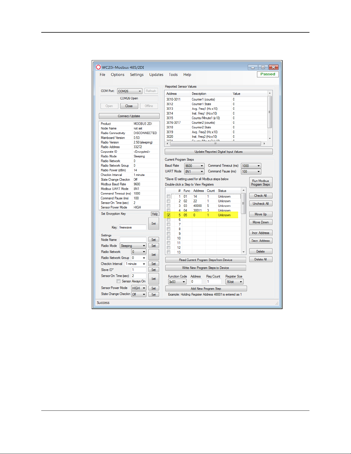
7.2. Change the Address of Program Steps
1. In the Registers table, click the check box next to the program step to change its address.
Figure 36: Selected Program Step in the WC20i-485-2DI Device
Configuration window
2. Click the Incr. Address button to increase the address value of the selected Program
Step.
3. Click the Decr. Address button to decrease the address value of the selected Program
Step.
LUM0096AA Rev Apr-2018 Page 50 of 100 Copyright © 2018FreeWave
This document is the property of FreeWave Technologies, Inc. and contains proprietary information owned by
FreeWave. This document cannot be reproduced in whole or in part by any means without written permission from
FreeWave Technologies, Inc.
Page 51

7. Modbus Program Steps Configuration
Figure 37: Selected Program Step with Increased Address Value
4. Click the Write New Program Steps to Device button to save the changes to the WC20i
every time the Program Steps are changed.
5. Click the Run Modbus Program Steps button to run the Program Steps to poll the
Modbus device on each check-in.
6. On the WC20i, press the Check-in button to apply power to the configured sensor, read
the sensor values, and send the collected sensor data to the Gateway.
7. Verify the Gateway is communicating with the Endpoints.
Note: A successful connection on the WAVECONTACT Endpoint is indicated with Green
blinking TX and ACT lights and a Red blinking light for RX.
If the connection is NOT successful, a Green blinking TX light appears for 10 seconds.
LUM0096AA Rev Apr-2018 Page 51 of 100 Copyright © 2018FreeWave
This document is the property of FreeWave Technologies, Inc. and contains proprietary information owned by
FreeWave. This document cannot be reproduced in whole or in part by any means without written permission from
FreeWave Technologies, Inc.
Page 52

WC20i Modular Endpoints - 485-2DI Modbus: User - Reference Manual
FREEWAVE Recommends: Install and configure the WC45i Gateway before any
Endpoints to ensure the Endpoints have connectivity after installation.
8. Close the WC Toolkit software.
9. Remove the WC-USB-4PIN 4-pin to USB programming cable from the computer and the
WC20i.
10. As applicable, replace the Endpoint cover.
11. Install the WC20i using the Direct Mount to Sensor with Short Conduit (on page 61).
12. If this is a WC20i-485-2DI-S installation, follow the tank level manufacturer's installation
procedures for the selected solar mounting kit listed in Available Accessories (on page 94).
LUM0096AA Rev Apr-2018 Page 52 of 100 Copyright © 2018FreeWave
This document is the property of FreeWave Technologies, Inc. and contains proprietary information owned by
FreeWave. This document cannot be reproduced in whole or in part by any means without written permission from
FreeWave Technologies, Inc.
Page 53

7. Modbus Program Steps Configuration
7.3. Delete Program Steps
1. In the Registers table, click the check box next to the program step to delete.
Figure 38: Selected Program Step in the WC20i-485-2DI Device
Configuration window
2. Click the Delete button to IMMEDIATELY remove the selected Program Step from the
table.
3. Click the Write New Program Steps to Device button to save the changes to the WC20i
every time the Program Steps are changed.
4. Click the Run Modbus Program Steps button to run the Program Steps to poll the
Modbus device on each check-in.
5. On the WC20i, press the Check-in button to apply power to the configured sensor, read
the sensor values, and send the collected sensor data to the Gateway.
LUM0096AA Rev Apr-2018 Page 53 of 100 Copyright © 2018FreeWave
This document is the property of FreeWave Technologies, Inc. and contains proprietary information owned by
FreeWave. This document cannot be reproduced in whole or in part by any means without written permission from
FreeWave Technologies, Inc.
Page 54

WC20i Modular Endpoints - 485-2DI Modbus: User - Reference Manual
6. Verify the Gateway is communicating with the Endpoints.
Note: A successful connection on the WAVECONTACT Endpoint is indicated with Green
blinking TX and ACT lights and a Red blinking light for RX.
If the connection is NOT successful, a Green blinking TX light appears for 10 seconds.
FREEWAVE Recommends: Install and configure the WC45i Gateway before any
Endpoints to ensure the Endpoints have connectivity after installation.
7. Close the WC Toolkit software.
8. Remove the WC-USB-4PIN 4-pin to USB programming cable from the computer and the
WC20i.
9. As applicable, replace the Endpoint cover.
10. Install the WC20i using the Direct Mount to Sensor with Short Conduit (on page 61).
11. If this is a WC20i-485-2DI-S installation, follow the tank level manufacturer's installation
procedures for the selected solar mounting kit listed in Available Accessories (on page 94).
LUM0096AA Rev Apr-2018 Page 54 of 100 Copyright © 2018FreeWave
This document is the property of FreeWave Technologies, Inc. and contains proprietary information owned by
FreeWave. This document cannot be reproduced in whole or in part by any means without written permission from
FreeWave Technologies, Inc.
Page 55

7. Modbus Program Steps Configuration
7.3.1. Delete All Program Steps
1. Click the Check All button to select all the current Program Steps in the table.
Figure 39: All Program Step Selected in the WC20i-485-2DI Device
Configuration window
2. Click the Delete All button to IMMEDIATELY remove all selected Program Steps from the
table.
3. Click the Write New Program Steps to Device button to save the changes to the WC20i
every time the Program Steps are changed.
4. Click the Run Modbus Program Steps button to run the Program Steps to poll the
Modbus device on each check-in.
5. On the WC20i, press the Check-in button to apply power to the configured sensor, read
the sensor values, and send the collected sensor data to the Gateway.
LUM0096AA Rev Apr-2018 Page 55 of 100 Copyright © 2018FreeWave
This document is the property of FreeWave Technologies, Inc. and contains proprietary information owned by
FreeWave. This document cannot be reproduced in whole or in part by any means without written permission from
FreeWave Technologies, Inc.
Page 56

WC20i Modular Endpoints - 485-2DI Modbus: User - Reference Manual
6. Verify the Gateway is communicating with the Endpoints.
Note: A successful connection on the WAVECONTACT Endpoint is indicated with Green
blinking TX and ACT lights and a Red blinking light for RX.
If the connection is NOT successful, a Green blinking TX light appears for 10 seconds.
FREEWAVE Recommends: Install and configure the WC45i Gateway before any
Endpoints to ensure the Endpoints have connectivity after installation.
7. Close the WC Toolkit software.
8. Remove the WC-USB-4PIN 4-pin to USB programming cable from the computer and the
WC20i.
9. As applicable, replace the Endpoint cover.
10. Install the WC20i using the Direct Mount to Sensor with Short Conduit (on page 61).
11. If this is a WC20i-485-2DI-S installation, follow the tank level manufacturer's installation
procedures for the selected solar mounting kit listed in Available Accessories (on page 94).
LUM0096AA Rev Apr-2018 Page 56 of 100 Copyright © 2018FreeWave
This document is the property of FreeWave Technologies, Inc. and contains proprietary information owned by
FreeWave. This document cannot be reproduced in whole or in part by any means without written permission from
FreeWave Technologies, Inc.
Page 57
7. Modbus Program Steps Configuration
7.4. Re-order Program Steps
1. In the Registers table, click the check box next to the program step to move.
Figure 40: Selected Program Step in the WC20i-485-2DI Device
Configuration window
2. Click the Move Up button to move a selected Program Step up in the program to its new
location.
3. Click the Move Down button to move a selected Program Step down in the program to its
new location.
LUM0096AA Rev Apr-2018 Page 57 of 100 Copyright © 2018FreeWave
This document is the property of FreeWave Technologies, Inc. and contains proprietary information owned by
FreeWave. This document cannot be reproduced in whole or in part by any means without written permission from
FreeWave Technologies, Inc.
Page 58

WC20i Modular Endpoints - 485-2DI Modbus: User - Reference Manual
Figure 41: Selected Program Step Moved Up
4. Click the Write New Program Steps to Device button to save the changes to the WC20i
every time the Program Steps are changed.
5. Click the Run Modbus Program Steps button to run the Program Steps to poll the
Modbus device on each check-in.
6. On the WC20i, press the Check-in button to apply power to the configured sensor, read
the sensor values, and send the collected sensor data to the Gateway.
7. Verify the Gateway is communicating with the Endpoints.
Note: A successful connection on the WAVECONTACT Endpoint is indicated with Green
blinking TX and ACT lights and a Red blinking light for RX.
If the connection is NOT successful, a Green blinking TX light appears for 10 seconds.
LUM0096AA Rev Apr-2018 Page 58 of 100 Copyright © 2018FreeWave
This document is the property of FreeWave Technologies, Inc. and contains proprietary information owned by
FreeWave. This document cannot be reproduced in whole or in part by any means without written permission from
FreeWave Technologies, Inc.
Page 59

7. Modbus Program Steps Configuration
FREEWAVE Recommends: Install and configure the WC45i Gateway before any
Endpoints to ensure the Endpoints have connectivity after installation.
8. Close the WC Toolkit software.
9. Remove the WC-USB-4PIN 4-pin to USB programming cable from the computer and the
WC20i.
10. As applicable, replace the Endpoint cover.
11. Install the WC20i using the Direct Mount to Sensor with Short Conduit (on page 61).
12. If this is a WC20i-485-2DI-S installation, follow the tank level manufacturer's installation
procedures for the selected solar mounting kit listed in Available Accessories (on page 94).
LUM0096AA Rev Apr-2018 Page 59 of 100 Copyright © 2018FreeWave
This document is the property of FreeWave Technologies, Inc. and contains proprietary information owned by
FreeWave. This document cannot be reproduced in whole or in part by any means without written permission from
FreeWave Technologies, Inc.
Page 60

WC20i Modular Endpoints - 485-2DI Modbus: User - Reference Manual
8. Mounting, Battery Replacement, Cleaning
l The WC20i:
l comes with a watertight ½” NPT female conduit fitting on the bottom mounting plate.
l is directly mounted to the sensor with a short section of conduit.
l Direct Mount to Sensor with Short Conduit (on page 61)
l Internal Lithium Battery Replacement (on page 62)
l Cleaning Instructions (on page 63)
Note: See Available Accessories (on page 94) for additional equipment.
LUM0096AA Rev Apr-2018 Page 60 of 100 Copyright © 2018FreeWave
This document is the property of FreeWave Technologies, Inc. and contains proprietary information owned by
FreeWave. This document cannot be reproduced in whole or in part by any means without written permission from
FreeWave Technologies, Inc.
Page 61

8. Mounting, Battery Replacement, Cleaning
8.1. Direct Mount to Sensor with Short Conduit
This mounting method uses a short conduit run from the sensor and the unit is held in place by the
conduit.
Figure 42: WC20i-485-2DI or WC20i-485-2DI-S Modular Endpoint Direct Mount
LUM0096AA Rev Apr-2018 Page 61 of 100 Copyright © 2018FreeWave
This document is the property of FreeWave Technologies, Inc. and contains proprietary information owned by
FreeWave. This document cannot be reproduced in whole or in part by any means without written permission from
FreeWave Technologies, Inc.
Page 62

WC20i Modular Endpoints - 485-2DI Modbus: User - Reference Manual
8.2. Internal Lithium Battery Replacement
Warning! Use of any battery other than the WAVECONTACT Internal Lithium Battery Pack
(FreeWave Part # WC-3BAT-IS) will impair the protection provided by the equipment.
AVERTISSEMENT: L'utilisation d'une pile autre que la référence WAVECONTACT Internal
Lithium Battery Pack (FreeWave Part # WC-3BAT-IS compromettra la protection fournie par
l'équipement.
Note: See Available Accessories (on page 94) for the FreeWave Part # to order the correct
replacement battery.
Warning! If the Internal Lithium Battery Pack is installed, the External Solar Battery system or
other power source MUST NOT BE connected!
Note: Battery Packs can be changed with the Endpoint in place.
1. Using the Philips screwdriver, remove the four screws holding down the WC20i cover and
remove the cover.
Use the WC20i cover to hold the four screws while configuring the WC20i or when
connecting or replacing the battery.
2. Depress the locking clip on the Internal Lithium Battery connection and unplug the
battery from the PCB.
3. Loosen the screw holding the battery door and slide the old battery out.
4. Slide in the new battery pack and tighten the battery door screw.
5. Connect the battery to the PCB battery connector.
6. Place the cover back on the WC20i.
7. Tighten the cover of the WC20i with the four screws removed in Step 1.
LUM0096AA Rev Apr-2018 Page 62 of 100 Copyright © 2018FreeWave
This document is the property of FreeWave Technologies, Inc. and contains proprietary information owned by
FreeWave. This document cannot be reproduced in whole or in part by any means without written permission from
FreeWave Technologies, Inc.
Page 63

8. Mounting, Battery Replacement, Cleaning
8.3. Cleaning Instructions
The outside of the enclosure may be cleaned with water, mild soap, and a damp cloth as needed.
Caution: High pressure washing is NOT recommended.
Warning! Electrostatic Discharge Hazard!
Care must be taken to avoid the potential of creating a change on the enclosure or antenna.
Do NOT wipe with a dry cloth.
Do NOT brush against the enclosure with clothing or gloves.
AVERTISSEMENT: Risque de décharge électrostatique! Il faut veiller à éviter tout risque de
changement de l'enceinte ou de l'antenne.
Ne pas essuyer avec un chiffon sec.
Ne pas brosser contre l'enceinte avec des vêtements ou des gants.
LUM0096AA Rev Apr-2018 Page 63 of 100 Copyright © 2018FreeWave
This document is the property of FreeWave Technologies, Inc. and contains proprietary information owned by
FreeWave. This document cannot be reproduced in whole or in part by any means without written permission from
FreeWave Technologies, Inc.
Page 64

WC20i Modular Endpoints - 485-2DI Modbus: User - Reference Manual
9. WC Toolkit Software Environment
The WC Toolkit software environment uses these windows to configure all WAVECONTACT
devices:
l Device Configuration window (on page 65)
l Digital Input Debounce window (on page 74)
l State Change Latch Settings window (on page 76)
LUM0096AA Rev Apr-2018 Page 64 of 100 Copyright © 2018FreeWave
This document is the property of FreeWave Technologies, Inc. and contains proprietary information owned by
FreeWave. This document cannot be reproduced in whole or in part by any means without written permission from
FreeWave Technologies, Inc.
Page 65

9. WC Toolkit Software Environment
9.1. Device Configuration window
The Device Configuration window is used to configure the settings on the WC20i-485-2DI or
WC20i-485-2DI-S Modular Endpoint.
Access and Window Description
1. Verify the WC Toolkit software is installed on the computer connected to the WC20i.
Note: See WC Toolkit Installation (on page 24) and WC Toolkit Update (on page 31).
2. Verify the Gateway is installed and configured before continuing with the Endpoint
configuration.
3. Connect the WC-USB-4PIN - 4-pin to USB programming cable to the computer and the
WC20i.
4. Open the WC Toolkit software.
The Select Device window opens. (Figure 43)
Figure 43: Select Device window
3. Click the Refresh button to have WC Toolkit search for and list the available COM ports
reported by Windows and connected devices in the COM Port list box.
4. Click the COM Port list box arrow and select the COM port on the computer associated
with the connected WC20i-485-2DI or WC20-485-2DI-S.
5. Click the Auto-Detect Device on COM Port button to have WC Toolkit connect the
device to the COM Port selected in the COM Port list box.
Note: Optional: Click the Select Device list box arrow and select the connected device.
The Device Configuration window opens for the selected device.
LUM0096AA Rev Apr-2018 Page 65 of 100 Copyright © 2018FreeWave
This document is the property of FreeWave Technologies, Inc. and contains proprietary information owned by
FreeWave. This document cannot be reproduced in whole or in part by any means without written permission from
FreeWave Technologies, Inc.
Page 66

WC20i Modular Endpoints - 485-2DI Modbus: User - Reference Manual
Figure 44: Device Configuration window:
WC20i-485-2DI or WC20i-485-2DI-S
LUM0096AA Rev Apr-2018 Page 66 of 100 Copyright © 2018FreeWave
This document is the property of FreeWave Technologies, Inc. and contains proprietary information owned by
FreeWave. This document cannot be reproduced in whole or in part by any means without written permission from
FreeWave Technologies, Inc.
Page 67

9. WC Toolkit Software Environment
Device Configuration window: WC20i-485-2DI or WC20i-485-2DI-S
Control Area Control Title Control Description
1 - Status of
Last Operation
text box
The Status of Last Operation text box indicates whether the
last command from the WC Toolkit to the connected device is
Active or has Passed.
Note: A Firmware Update Available message appears
in this text box when the WC Toolkit has detected that a
newer version of firmware is available for download than
what is installed on the device.
Note: This information is read-only.
2 - Serial Port
Settings area
The Serial Port Settings area shows the connected COM port
and is used to re-connect to the COM port if the connection is
lost.
2 - Serial Port
Settings area
COM Port list
box
Click the COM Port list box arrow and select the COM port on
the computer associated with the connected WC20i-485-2DI or
WC20-485-2DI-S.
2 - Serial Port
Settings area
Refresh button Click the Refresh button to have WC Toolkit search for and list
the available COM ports reported by Windows and connected
devices in the COM Port list box.
2 - Serial Port
Settings area
COM text box The COM text box shows the COM port the WAVECONTACT
device is connected to.
Note: This information is read-only.
2 - Serial Port
Settings area
Open button Click the Open button to re-connect the WAVECONTACT
device to the COM port.
2 - Serial Port
Settings area
Close button Click the Close button to disconnect the WAVECONTACT
device from the COM port.
2 - Serial Port
Settings area
Offline button Click the Offline button to disconnect the WAVECONTACT
device from the COM port but continue to configure the device
offline.
2 - Serial Port
Settings area
Connect /
Update button
Click the Connect / Update button to re-connect to the COM
port of the WAVECONTACT device.
Note: When the connection is made to the IP Address,
full access to the Gateway is available as if a direct
serial connection is used.
This includes full remote configuration capability.
LUM0096AA Rev Apr-2018 Page 67 of 100 Copyright © 2018FreeWave
This document is the property of FreeWave Technologies, Inc. and contains proprietary information owned by
FreeWave. This document cannot be reproduced in whole or in part by any means without written permission from
FreeWave Technologies, Inc.
Page 68

WC20i Modular Endpoints - 485-2DI Modbus: User - Reference Manual
Device Configuration window: WC20i-485-2DI or WC20i-485-2DI-S
Control Area Control Title Control Description
3 - Reported
Sensor Values
area
The Reported Sensor Values area shows the reported data
values from the attached sensor.
Note: This information is read-only.
4 - Information
area
The Information area of the Device Configuration window
shows connection information about the connected
WAVECONTACT device.
Note: This information is read-only.
5 - Set
Encryption
Key area
The Set Encryption Key area is used to activate and define the
encryption key for the WAVECONTACT device.
5 - Set
Encryption
Key area
Help button Click to open the Encryption Help message.
5 - Set
Encryption
Key area
Key text box In the Key text box, enter the encryption key for the device
using 6 to 16 characters.
Important!: A Key CANNOT contain spaces or angle
brackets.
The Gateway and Endpoints only communicate if they
are configured with the same Key.
5 - Set
Encryption
Key area
Set button Click the Set button to save the information.
6 - Settings
area
The Settings area is used to define the radio mode and radio
network.
Note: See the Settings area (on page 69) for detailed
information about the settings.
7 - Current
Program
Steps
The Current Program Steps area is used to define the Modbus
operation codes for each poll check-in.
Note: See the Current Program Steps area (on page 71)
for detailed information about the settings.
LUM0096AA Rev Apr-2018 Page 68 of 100 Copyright © 2018FreeWave
This document is the property of FreeWave Technologies, Inc. and contains proprietary information owned by
FreeWave. This document cannot be reproduced in whole or in part by any means without written permission from
FreeWave Technologies, Inc.
Page 69

9. WC Toolkit Software Environment
Device Configuration window: Settings area
Control Title Control Description
Set button Click the Set button to save the information.
Node Name text
box
Optional: In the Node Name text box, enter a name for the Endpoint using a
maximum of 10 characters.
Radio Mode list
box
Click the Radio Mode list box arrow and select either Sleeping or Non-
Sleeping.
l Sleeping: Select Sleeping to reduce power consumption and to use the
designated Checkin Interval list box to connect with the Gateway.
l Non-Sleeping: Select Non-Sleeping to always be in communication with the
Gateway.
l Non-Sleeping devices automatically act as Mesh Endpoint / Repeaters
between other Endpoints and the Gateway.
Note: The default value is Sleeping.
Radio Network
list box
Click the Radio Network list box arrow and select 0 (zero) to 7 for the assigned
number.
Note: The default value is 1.
Important!: The Radio Network and Radio Network Group settings are
selected by the user but MUST MATCH the existing Gateway network for
successful communication between the Gateway and Endpoint.
See WAVECONTACT Network Frequencies (on page 78) for additional
information.
Radio Network
Group list box
Click the Radio Network Group list box arrow and select 0 (zero) to 29 for the
network group assigned number.
Note: The default value is 10.
Important!: The Radio Network and Radio Network Group settings are
selected by the user but MUST MATCH the existing Gateway network for
successful communication between the Gateway and Endpoint.
See WAVECONTACT Network Frequencies (on page 78) for additional
information.
9.1.1. Settings area
The Settings area is used to define the radio mode and radio network.
LUM0096AA Rev Apr-2018 Page 69 of 100 Copyright © 2018FreeWave
This document is the property of FreeWave Technologies, Inc. and contains proprietary information owned by
FreeWave. This document cannot be reproduced in whole or in part by any means without written permission from
FreeWave Technologies, Inc.
Page 70

WC20i Modular Endpoints - 485-2DI Modbus: User - Reference Manual
Device Configuration window: Settings area
Control Title Control Description
Checkin
Interval list box
Click the Checkin Interval list box arrow and select how often the Endpoint
wakes up, reads the sensor values , and transmits the data to the Gateway.
The options are:
l 5 seconds
l 15 seconds
l 1 minute
l 2 minutes
l 4.5 minutes
l 10 minutes
l 15 minutes
l 30 minutes
l 60 minutes
Note: The default value is 5 seconds.
Slave ID text
box
In the Slave ID column / text box, enter the remote source Endpoint Modbus
Slave ID.
Important!: Verify there are no duplicate Slave IDs in a given network.
The Gateway only caches one set of data for each Slave ID.
A duplicate is overwritten.
Sensor On
Time (sec) text
box
FREEWAVE Recommends: Accept the default Sensor On time (sec)
value of 2 seconds for most devices.
However, radar sensors often require a longer warm-up time.
Contact the sensor manufacturer for details.
Sensor Always
On check box
Note: Having the Sensor Always On selected is useful for rapid data
collection on a sensor that has a long warm-up time.
However, it will shorten the battery life dramatically unless a Solar
Powered WC20i is used.
Sensor Power
Mode list box
Note: HIGH outputs 18.5 volts to the sensor and LOW outputs 12.5 volts.
LOW results in longer battery life but some sensors require a higher
voltage.
State Change
Checkin list box
Click the State Change Checkin list box arrow and select Yes to check on a
change of state at the input rather than waiting for the check in time to expire.
Note: The default value is No.
LUM0096AA Rev Apr-2018 Page 70 of 100 Copyright © 2018FreeWave
This document is the property of FreeWave Technologies, Inc. and contains proprietary information owned by
FreeWave. This document cannot be reproduced in whole or in part by any means without written permission from
FreeWave Technologies, Inc.
Page 71

9. WC Toolkit Software Environment
Device Configuration window: Current Program Steps area
Control Area Control Title Control Description
7 - Current
Program Steps
The Current Program Steps area is used to define the
Modbus operation codes for each poll check-in.
7 - Current
Program Steps
Baud Rate list
box
Click the Baud Rate list box arrow and select the baud rate for
the RS485 Modbus port.
7 - Current
Program Steps
UART Mode
list box
Click the UART Mode list box arrow and select the number of
data bits, parity, and stop bits used with the RS485 Modbus
port.
7 - Current
Program Steps
Command
Timeout (ms)
list box
Click the Command Timeout (ms) list box arrow and select
the number of mS the device waits for a response from the
attached Modbus device before it times out the request.
The options are:
l 500
l 1000
l 1500
l 2000
l 2500
l 3000
7 - Current
Program Steps
Command
Pause (ms) list
box
Click the Command Pause (ms) list box arrow and select the
number of mS the device pauses between each Modbus
transaction.
The options are:
l 50
l 100
l 150
l 200
l 250
l 500
l 1000
l 1500
l 2000
7 - Current
Program Steps
Registers table The Registers table shows the available Program Steps of the
connected Modbus device.
7 - Current
Program Steps
Run Modbus
Program Steps
button
Click the Run Modbus Program Steps button to run the
Program Steps to poll the Modbus device on each check-in.
7 - Current
Program Steps
Check All
button
Click the Check All button to select all the current Program
Steps in the table.
7 - Current
Program Steps
Uncheck All
button
Click the Uncheck All button to clear all of the selected
Program Steps in the table.
7 - Current
Program Steps
Move Up button Click the Move Up button to move a selected Program Step up
in the program to its new location.
7 - Current
Program Steps
Move Down
button
Click the Move Down button to move a selected Program
Step down in the program to its new location.
9.1.2. Current Program Steps area
LUM0096AA Rev Apr-2018 Page 71 of 100 Copyright © 2018FreeWave
This document is the property of FreeWave Technologies, Inc. and contains proprietary information owned by
FreeWave. This document cannot be reproduced in whole or in part by any means without written permission from
FreeWave Technologies, Inc.
Page 72

WC20i Modular Endpoints - 485-2DI Modbus: User - Reference Manual
Device Configuration window: Current Program Steps area
Control Area Control Title Control Description
7 - Current
Program Steps
Incr. Address
button
Click the Incr. Address button to increase the address value
of the selected Program Step.
7 - Current
Program Steps
Decr. Address
button
Click the Decr. Address button to decrease the address value
of the selected Program Step.
7 - Current
Program Steps
Delete button Click the Delete button to IMMEDIATELY remove the
selected Program Step from the table.
7 - Current
Program Steps
Delete All
button
Click the Delete All button to IMMEDIATELY remove all
selected Program Steps from the table.
7 - Current
Program Steps
Read Current
Program Steps
from Device
button
Click the Read Current Program Steps from Device button
to view the current Program Steps in the table.
7 - Current
Program Steps
Write New
Program Steps
to Device
button
Click the Write New Program Steps to Device button to
save the changes to the WC20i every time the Program Steps
are changed.
7 - Current
Program Steps
Function Code
list box
Click the Function Code list box arrow and select the
operation code for the step.
The options are:
l 0x01 for MODBUS_READ_COIL (limit: 1 coil)
l 0x02 MODBUS_READ_INPUT (limit: 1 input)
l 0x03 for MODBUS_READ_HOLDING_REGISTERS
l 0x04 for MODBUS_READ_INPUT_REGISTERS
l 0x05 for MODBUS_WRITE_SINGLE_COIL
7 - Current
Program Steps
Address text
box
In the Address text box, enter the Modbus Register Address
of the connected Modbus device.
7 - Current
Program Steps
Coil Count text
box
Note: The Coil Count text box is only visible when
0x01 is selected in the Function Code list box.
The default value is 1.
This information is read-only.
7 - Current
Program Steps
Input Count
text box
Note: The Input Count text box is only visible when
0x02 is selected in the Function Code list box.
The default value is 1.
This information is read-only.
LUM0096AA Rev Apr-2018 Page 72 of 100 Copyright © 2018FreeWave
This document is the property of FreeWave Technologies, Inc. and contains proprietary information owned by
FreeWave. This document cannot be reproduced in whole or in part by any means without written permission from
FreeWave Technologies, Inc.
Page 73

9. WC Toolkit Software Environment
Device Configuration window: Current Program Steps area
Control Area Control Title Control Description
7 - Current
Program Steps
Reg Count text
box
In the Reg Count text box, enter the number of consecutive
Modbus blocks to read or write.
Note: The Reg Count text box is only available if 0x03
or 0x04 is selected in the Function Code list box.
7 - Current
Program Steps
Coil Value text
box
In the Coil Value text box, enter corresponding coil ID number
of the connected Modbus device.
Note: The Coil Value text box is only available if 0x05
is selected in the Function Code list box.
7 - Current
Program Steps
Register Size
list box
Click the Register Size list box arrow and select the
designated register size in bits.
The default value is 16-bit.
Note: The Register Size list box is only available if
0x03 or 0x04 is selected in the Function Code list box.
7 - Current
Program Steps
Add New
Program Step
button
Click the Add New Program Step button to add a new
Program Step to the table.
LUM0096AA Rev Apr-2018 Page 73 of 100 Copyright © 2018FreeWave
This document is the property of FreeWave Technologies, Inc. and contains proprietary information owned by
FreeWave. This document cannot be reproduced in whole or in part by any means without written permission from
FreeWave Technologies, Inc.
Page 74

WC20i Modular Endpoints - 485-2DI Modbus: User - Reference Manual
Digital Input Debounce window
Control Title Control Description
Debounce Time
(ms) Input 1 or
Input 2 text boxes
In the Debounce Time (ms) Input 1 or Input 2 text boxes, enter the time (in
mS) during which possible multiple triggers are treated as a single event.
Note: This is typically used when mechanical contacts are used to
generate the input signal.
9.2. Digital Input Debounce window
The Digital Input Debounce window is used to designate the digital input Debounce Time to
accurately total Digital Input counts.
Note: The Debounce Time is useful when using contacts that may produce extra counts when they
close.
Example: A typical value for a dry contact is 100mS. Any extra counts due to contact bounce within
the Debounce Time setting are ignored.
Access and Window Description
1. Open the Device Configuration window (on page 65).
2. On the Settings menu, click Digital Input Debounce.
Figure 45: Settings menu > Digital Input Debounce
The Digital Input Debounce window opens.
Figure 46: Digital Input Debounce window
LUM0096AA Rev Apr-2018 Page 74 of 100 Copyright © 2018FreeWave
This document is the property of FreeWave Technologies, Inc. and contains proprietary information owned by
FreeWave. This document cannot be reproduced in whole or in part by any means without written permission from
FreeWave Technologies, Inc.
Page 75

9. WC Toolkit Software Environment
Digital Input Debounce window
Control Title Control Description
Read Debounce
Time button
Click the Read Debounce Time button to read the current debounce settings.
This information appears in the Debounce Time (ms) Input 1 or Input 2 text
boxes.
Write Debounce
Time button
Click the Write Debounce Time button to save the time entered in the
Debounce Time (ms) Input 1 or Input 2 text boxes to the WC20i.
LUM0096AA Rev Apr-2018 Page 75 of 100 Copyright © 2018FreeWave
This document is the property of FreeWave Technologies, Inc. and contains proprietary information owned by
FreeWave. This document cannot be reproduced in whole or in part by any means without written permission from
FreeWave Technologies, Inc.
Page 76

WC20i Modular Endpoints - 485-2DI Modbus: User - Reference Manual
State Change Latch Settings window
Control Title Control Description
Input Channel 1
or 2 list boxes
Click the Input Channel 1 or Input Channel 2list box arrow and select either
Latch Open (0) or Latch Closed (1).
9.3. State Change Latch Settings window
The State Latch feature is used where a fast transition sensed by the WC20i-485-2DI may
happen too quickly to be read by the WC45i-Gateway.
The state of one or both of the digital inputs is latched to a value for a configurable number of
seconds.
Example: If the Input Channel 1 list box is set to Latch Closed (1) for the 3 seconds entered in the
Input Channel 1 or 2 Seconds text box, then any close sensed on the digital input is reported as
closed for 3 seconds even in the input opens in less than 3 seconds.
The State Change Latch Settings window is used to define the latch settings.
Access and Window Description
1. Open the Device Configuration window (on page 65).
2. On the Settings menu, click State Change Latch Settings.
Figure 47: Settings menu > State Change Latch Settings
The State Change Latch Settings window opens.
Figure 48: State Change Latch Settings window
LUM0096AA Rev Apr-2018 Page 76 of 100 Copyright © 2018FreeWave
This document is the property of FreeWave Technologies, Inc. and contains proprietary information owned by
FreeWave. This document cannot be reproduced in whole or in part by any means without written permission from
FreeWave Technologies, Inc.
Page 77

9. WC Toolkit Software Environment
State Change Latch Settings window
Control Title Control Description
Input Channel 1
or 2 Seconds text
boxes
In the Input Channel 1 or Input Channel 2 Seconds text boxes, enter the
number of seconds the latch remains open or closed.
Read State Latch
Settings button
Click the Read State Latch Settings button to read the current state of the
latch settings.
Write State Latch
Settings button
Click the Write State Latch Settings button to write (save) the changed latch
settings.
LUM0096AA Rev Apr-2018 Page 77 of 100 Copyright © 2018FreeWave
This document is the property of FreeWave Technologies, Inc. and contains proprietary information owned by
FreeWave. This document cannot be reproduced in whole or in part by any means without written permission from
FreeWave Technologies, Inc.
Page 78

10. WAVECONTACT Network Frequencies
The frequencies used by the WAVECONTACT network vary depending on the Radio Network and Radio Network Group selected in
the Device Configuration window (on page 65).
Example: Using the Radio Network Group Selection: 0, 1, 2, or 3 (on page 79) table, the Radio Network and Radio Network Group settings
of 0 (zero) and 0 (zero) (respectively) uses the frequencies between 908.20 and 918.20.
The Radio Network and Radio Network Group settings of 0 (zero) and 2 (respectively) uses 905.00 to 915.00.
l Radio Network Group Selection: 0, 1, 2, or 3 (on page 79)
l Radio Network Group Selection: 4, 5, 6, or 7 (on page 80)
l Radio Network Group Selection: 8, 9, 10, 11 (on page 81)
l Radio Network Group Selection: 12, 13, 14, 15 (on page 82)
l Radio Network Group Selection: 16, 17, 18, or 19 (on page 83)
l Radio Network Group Selection: 20, 21, 22, 23 (on page 84)
l Radio Network Group Selection: 28 or 29 (on page 86)
LUM0096AA Rev Apr-2018 Page 78 of 100 Copyright © 2018FreeWave
This document is the property of FreeWave Technologies, Inc. and contains proprietary information owned by FreeWave. This document cannot be reproduced
in whole or in part by any means without written permission from FreeWave Technologies, Inc.
Page 79

10. WAVECONTACT Network Frequencies
Radio Network
selection
Radio
Network Group
selection:
0 or 1
Low
Frequency
High
Frequency
Radio Network
selection
Radio
Network Group
selection:
2 or 3
Low
Frequency
High
Frequency
0 0 908.20 918.20 0 2 905.00 915.00
1 0 908.40 918.40 1 2 905.20 915.20
2 0 908.60 918.60 2 2 905.40 915.40
3 0 908.80 918.80 3 2 905.60 915.60
4 0 909.00 919.00 4 2 905.80 915.80
5 0 909.20 919.20 5 2 906.00 916.00
6 0 909.40 919.40 6 2 906.20 916.20
7 0 909.60 919.60 7 2 906.40 916.40
0 1 909.80 919.80 0 3 906.60 916.60
1 1 910.00 920.00 1 3 906.80 916.80
2 1 910.20 920.20 2 3 907.00 917.00
3 1 910.40 920.40 3 3 907.20 917.20
4 1 910.60 920.60 4 3 907.40 917.40
5 1 910.80 920.80 5 3 907.60 917.60
6 1 911.00 921.00 6 3 907.80 917.80
7 1 911.20 921.20 7 3 908.00 918.00
10.1. Radio Network Group Selection: 0, 1, 2, or 3
In the Device Configuration window (on page 65), these are the High and Low Frequencies when the
Radio Network Group list box selection is 0, 1, 2, or 3.
LUM0096AA Rev Apr-2018 Page 79 of 100 Copyright © 2018FreeWave
This document is the property of FreeWave Technologies, Inc. and contains proprietary information owned by FreeWave. This document cannot be reproduced
in whole or in part by any means without written permission from FreeWave Technologies, Inc.
Page 80

WC20i Modular Endpoints - 485-2DI Modbus
Radio Network
selection
Radio
Network Group
selection:
4 or 5
Low
Frequency
High
Frequency
Radio Network
selection
Radio
Network Group
selection:
6 or 7
Low
Frequency
High
Frequency
0 4 908.20 918.20 0 6 905.00 915.00
1 4 908.40 918.40 1 6 905.20 915.20
2 4 908.60 918.60 2 6 905.40 915.40
3 4 908.80 918.80 3 6 905.60 915.60
4 4 909.00 919.00 4 6 905.80 915.80
5 4 909.20 919.20 5 6 906.00 916.00
6 4 909.40 919.40 6 6 906.20 916.20
7 4 909.60 919.60 7 6 906.40 916.40
0 5 909.80 919.80 0 7 906.60 916.60
1 5 910.00 920.00 1 7 906.80 916.80
2 5 910.20 920.20 2 7 907.00 917.00
3 5 910.40 920.40 3 7 907.20 917.20
4 5 910.60 920.60 4 7 907.40 917.40
5 5 910.80 920.80 5 7 907.60 917.60
6 5 911.00 921.00 6 7 907.80 917.80
7 5 911.20 921.20 7 7 908.00 918.00
10.2. Radio Network Group Selection: 4, 5, 6, or 7
In the Device Configuration window (on page 65), these are the High and Low Frequencies when the
Radio Network Group list box selection is 4, 5, 6, or 7.
LUM0096AA Rev Apr-2018 Page 80 of 100 Copyright © 2018FreeWave
This document is the property of FreeWave Technologies, Inc. and contains proprietary information owned by FreeWave. This document cannot be reproduced
in whole or in part by any means without written permission from FreeWave Technologies, Inc.
Page 81

10. WAVECONTACT Network Frequencies
Radio Network
selection
Radio
Network Group
selection:
8 or 9
Low
Frequency
High
Frequency
Radio Network
selection
Radio
Network Group
selection:
10 or 11
Low
Frequency
High
Frequency
0 8 908.20 918.20 0 10 905.00 915.00
1 8 908.40 918.40 1 10 905.20 915.20
2 8 908.60 918.60 2 10 905.40 915.40
3 8 908.80 918.80 3 10 905.60 915.60
4 8 909.00 919.00 4 10 905.80 915.80
5 8 909.20 919.20 5 10 906.00 916.00
6 8 909.40 919.40 6 10 906.20 916.20
7 8 909.60 919.60 7 10 906.40 916.40
0 9 909.80 919.80 0 11 906.60 916.60
1 9 910.00 920.00 1 11 906.80 916.80
2 9 910.20 920.20 2 11 907.00 917.00
3 9 910.40 920.40 3 11 907.20 917.20
4 9 910.60 920.60 4 11 907.40 917.40
5 9 910.80 920.80 5 11 907.60 917.60
6 9 911.00 921.00 6 11 907.80 917.80
7 9 911.20 921.20 7 11 908.00 918.00
10.3. Radio Network Group Selection: 8, 9, 10, 11
In the Device Configuration window (on page 65), these are the High and Low Frequencies when the
Radio Network Group list box selection is 8, 9, 10, or 11.
LUM0096AA Rev Apr-2018 Page 81 of 100 Copyright © 2018FreeWave
This document is the property of FreeWave Technologies, Inc. and contains proprietary information owned by FreeWave. This document cannot be reproduced
in whole or in part by any means without written permission from FreeWave Technologies, Inc.
Page 82

WC20i Modular Endpoints - 485-2DI Modbus
Radio Network
selection
Radio
Network Group
selection:
12 or 13
Low
Frequency
High
Frequency
Radio Network
selection
Radio
Network Group
selection:
14 or 15
Low
Frequency
High
Frequency
0 12 908.20 918.20 0 14 905.00 915.00
1 12 908.40 918.40 1 14 905.20 915.20
2 12 908.60 918.60 2 14 905.40 915.40
3 12 908.80 918.80 3 14 905.60 915.60
4 12 909.00 919.00 4 14 905.80 915.80
5 12 909.20 919.20 5 14 906.00 916.00
6 12 909.40 919.40 6 14 906.20 916.20
7 12 909.60 919.60 7 14 906.40 916.40
0 13 909.80 919.80 0 15 906.60 916.60
1 13 910.00 920.00 1 15 906.80 916.80
2 13 910.20 920.20 2 15 907.00 917.00
3 13 910.40 920.40 3 15 907.20 917.20
4 13 910.60 920.60 4 15 907.40 917.40
5 13 910.80 920.80 5 15 907.60 917.60
6 13 911.00 921.00 6 15 907.80 917.80
7 13 911.20 921.20 7 15 908.00 918.00
10.4. Radio Network Group Selection: 12, 13, 14, 15
In the Device Configuration window (on page 65), these are the High and Low Frequencies when the
Radio Network Group list box selection is 12, 13, 14, or 15.
LUM0096AA Rev Apr-2018 Page 82 of 100 Copyright © 2018FreeWave
This document is the property of FreeWave Technologies, Inc. and contains proprietary information owned by FreeWave. This document cannot be reproduced
in whole or in part by any means without written permission from FreeWave Technologies, Inc.
Page 83

10. WAVECONTACT Network Frequencies
Radio Network
selection
Radio
Network Group
selection:
16 or 17
Low
Frequency
High
Frequency
Radio Network
selection
Radio
Network Group
selection:
18 or 19
Low
Frequency
High
Frequency
0 16 908.20 918.20 0 18 905.00 915.00
1 16 908.40 918.40 1 18 905.20 915.20
2 16 908.60 918.60 2 18 905.40 915.40
3 16 908.80 918.80 3 18 905.60 915.60
4 16 909.00 919.00 4 18 905.80 915.80
5 16 909.20 919.20 5 18 906.00 916.00
6 16 909.40 919.40 6 18 906.20 916.20
7 16 909.60 919.60 7 18 906.40 916.40
0 17 909.80 919.80 0 19 906.60 916.60
1 17 910.00 920.00 1 19 906.80 916.80
2 17 910.20 920.20 2 19 907.00 917.00
3 17 910.40 920.40 3 19 907.20 917.20
4 17 910.60 920.60 4 19 907.40 917.40
5 17 910.80 920.80 5 19 907.60 917.60
6 17 911.00 921.00 6 19 907.80 917.80
7 17 911.20 921.20 7 19 908.00 918.00
10.5. Radio Network Group Selection: 16, 17, 18, or 19
In the Device Configuration window (on page 65), these are the High and Low Frequencies when the
Radio Network Group list box selection is 16, 17, 18, or 19.
LUM0096AA Rev Apr-2018 Page 83 of 100 Copyright © 2018FreeWave
This document is the property of FreeWave Technologies, Inc. and contains proprietary information owned by FreeWave. This document cannot be reproduced
in whole or in part by any means without written permission from FreeWave Technologies, Inc.
Page 84

WC20i Modular Endpoints - 485-2DI Modbus
Radio Network
selection
Radio
Network Group
selection:
20 or 21
Low
Frequency
High
Frequency
Radio Network
selection
Radio
Network Group
selection:
22 or 23
Low
Frequency
High
Frequency
0 20 908.20 918.20 0 22 905.00 915.00
1 20 908.40 918.40 1 22 905.20 915.20
2 20 908.60 918.60 2 22 905.40 915.40
3 20 908.80 918.80 3 22 905.60 915.60
4 20 909.00 919.00 4 22 905.80 915.80
5 20 909.20 919.20 5 22 906.00 916.00
6 20 909.40 919.40 6 22 906.20 916.20
7 20 909.60 919.60 7 22 906.40 916.40
0 21 909.80 919.80 0 23 906.60 916.60
1 21 910.00 920.00 1 23 906.80 916.80
2 21 910.20 920.20 2 23 907.00 917.00
3 21 910.40 920.40 3 23 907.20 917.20
4 21 910.60 920.60 4 23 907.40 917.40
5 21 910.80 920.80 5 23 907.60 917.60
6 21 911.00 921.00 6 23 907.80 917.80
7 21 911.20 921.20 7 23 908.00 918.00
10.6. Radio Network Group Selection: 20, 21, 22, 23
In the Device Configuration window (on page 65), these are the High and Low Frequencies when the
Radio Network Group list box selection is 20, 21, 22, or 23.
LUM0096AA Rev Apr-2018 Page 84 of 100 Copyright © 2018FreeWave
This document is the property of FreeWave Technologies, Inc. and contains proprietary information owned by FreeWave. This document cannot be reproduced
in whole or in part by any means without written permission from FreeWave Technologies, Inc.
Page 85

10. WAVECONTACT Network Frequencies
Radio Network
selection
Radio
Network Group
selection:
24 or 25
Low
Frequency
High
Frequency
Radio Network
selection
Radio
Network Group
selection:
26 or 27
Low
Frequency
High
Frequency
0 24 908.20 918.20 0 26 905.00 915.00
1 24 908.40 918.40 1 26 905.20 915.20
2 24 908.60 918.60 2 26 905.40 915.40
3 24 908.80 918.80 3 26 905.60 915.60
4 24 909.00 919.00 4 26 905.80 915.80
5 24 909.20 919.20 5 26 906.00 916.00
6 24 909.40 919.40 6 26 906.20 916.20
7 24 909.60 919.60 7 26 906.40 916.40
0 25 909.80 919.80 0 27 906.60 916.60
1 25 910.00 920.00 1 27 906.80 916.80
2 25 910.20 920.20 2 27 907.00 917.00
3 25 910.40 920.40 3 27 907.20 917.20
4 25 910.60 920.60 4 27 907.40 917.40
5 25 910.80 920.80 5 27 907.60 917.60
6 25 911.00 921.00 6 27 907.80 917.80
7 25 911.20 921.20 7 27 908.00 918.00
10.7. Radio Network Group Selection: 24, 25, 26, 27
In the Device Configuration window (on page 65), these are the High and Low Frequencies when the
Radio Network Group list box selection is 24, 25, 26, or 27.
LUM0096AA Rev Apr-2018 Page 85 of 100 Copyright © 2018FreeWave
This document is the property of FreeWave Technologies, Inc. and contains proprietary information owned by FreeWave. This document cannot be reproduced
in whole or in part by any means without written permission from FreeWave Technologies, Inc.
Page 86

Radio Network
selection
Radio
Network Group
selection:
28 or 29
Low
Frequency
High
Frequency
0 28 908.20 918.20
1 28 908.40 918.40
2 28 908.60 918.60
3 28 908.80 918.80
4 28 909.00 919.00
5 28 909.20 919.20
6 28 909.40 919.40
7 28 909.60 919.60
0 29 909.80 919.80
1 29 910.00 920.00
2 29 910.20 920.20
3 29 910.40 920.40
4 29 910.60 920.60
5 29 910.80 920.80
6 29 911.00 921.00
7 29 911.20 921.20
WC20i Modular Endpoints - 485-2DI Modbus
10.8. Radio Network Group Selection: 28 or 29
In the Device Configuration window (on page 65), these are the High and Low Frequencies when the
Radio Network Group list box selection is 28 or 29.
LUM0096AA Rev Apr-2018 Page 86 of 100 Copyright © 2018FreeWave
This document is the property of FreeWave Technologies, Inc. and contains proprietary information owned by FreeWave. This document cannot be reproduced
in whole or in part by any means without written permission from FreeWave Technologies, Inc.
Page 87

WC20i Modular Endpoints - 485-2DI Modbus: User - Reference Manual
Technical Specifications:
Specification Description
Transmitter
Frequency 902-928 MHz, FHSS, license-free ISM band compliant with FCC Part 15
Range Maximum of ½ mile
Data Update
Rates
l User selectable
l 5 seconds to 1 hour, typical
Networks Maximum of 65,520 separate networks
Receiver
Appendix A: Technical Specifications
Warning! Use of this equipment in a manner not specified by the manufacturer may impair the
protection provided by the equipment.
The use of any parts not supplied by the manufacturer violates the safety rating of the
equipment.
AVERTISSEMENT: L'utilisation de cet équipement d'une manière non spécifiée par le fabricant
peut nuire à la protection fournie par l'équipement.
L'utilisation de pièces non fournies par le fabricant est contraire à la cote de sécurité de
l'équipement.
Important!: The associated apparatus provides intrinsically safe outputs.
L’appareil associé fournit des sorties à sécurité intrinsèque.
See the Control Drawing: 960-0076-02 (on page 89) for requirements when used in a Class I Division
1 area.
LUM0096AA Rev Apr-2018 Page 87 of 100 Copyright © 2018FreeWave
This document is the property of FreeWave Technologies, Inc. and contains proprietary information owned by
FreeWave. This document cannot be reproduced in whole or in part by any means without written permission from
FreeWave Technologies, Inc.
Page 88

Appendix A: Technical Specifications
Technical Specifications:
Specification Description
Sensitivity -109dB
Interfaces
Data Interface Wireless, available as Modbus registers at Gateway
Internal
Diagnostics
l Battery voltage
l Signal Strength
l Error conditions
Power
Requirements
Battery Pack 3 X D Lithium battery pack, field replaceable.
FreeWave Part #: WC-3BAT-IS
Note: C1D1 certified when used with FreeWave system. Replacement can
be performed safely in hazardous locations.
Optional: C1D1 solar / battery module
Note: See Solar Powered WC20i (on page 10) for additional information.
Battery Life 1–10 years, depending on the sensor type and reporting frequency.
Radio Power 40mW
Sensor Power l Powers both the radio system and the sensor / transmitter.
l User configurable for 18 and 12.5V.
Note: Barriers and external power are not required.
General
Information
Operating
Temperature
-40°C to 60°C
Humidity 0% - 100% condensing
Enclosure Size 3.5 H × 5.0 W × 5.0 L (in)
Safety Rating l Intrinsically Safe
l Certified for use in Class I, Division 1 Groups C and D.
l EXi [EXi] FCC/IC Certified.
LUM0096AA Rev Apr-2018 Page 88 of 100 Copyright © 2018FreeWave
This document is the property of FreeWave Technologies, Inc. and contains proprietary information owned by
FreeWave. This document cannot be reproduced in whole or in part by any means without written permission from
FreeWave Technologies, Inc.
Page 89

WC20i Modular Endpoints - 485-2DI Modbus: User - Reference Manual
Appendix B: Control Drawing: 960-0076-02
Figure 49: Control Drawing: WC20i-485-2DI / WC20i-485-2DI-S
LUM0096AA Rev Apr-2018 Page 89 of 100 Copyright © 2018FreeWave
This document is the property of FreeWave Technologies, Inc. and contains proprietary information owned by
FreeWave. This document cannot be reproduced in whole or in part by any means without written permission from
FreeWave Technologies, Inc.
Page 90

WC20i Modular Endpoints - 485-2DI Modbus: User - Reference Manual
Remote Modbus Registers - WC20i-485-2DI / WC20i-485-2DI-S Status Registers
Register Number
Register Address
(Offset)
Description
43011-43012 3010-3011 32-bit Hardware counter
Note: 3010 = High Word (two registers).
43013 3012 Digital Input State
l 1 = closed
l 0 (zero) = open
43014 3013 Average frequency over the last check-in period
times 10.
Appendix C: Remote Modbus Registers
The WC20i sends data to a WC45i-Gateway.
Every check-in period, the sensors are read and data is sent to the Gateway. The Gateway saves
the data under the set Modbus ID in 16-bit registers.
l The data sent to the Gateway is available at the Gateway in registers where it is read by a
Modbus RTU master device.
l The Endpoint must have a unique (to the network it is in) Modbus Slave ID.
l The Gateway uses this Slave ID to store its unique data.
Note: The terms node and Endpoint are used interchangeably in this document.
LUM0096AA Rev Apr-2018 Page 90 of 100 Copyright © 2018FreeWave
This document is the property of FreeWave Technologies, Inc. and contains proprietary information owned by
FreeWave. This document cannot be reproduced in whole or in part by any means without written permission from
FreeWave Technologies, Inc.
Page 91

Appendix C: Remote Modbus Registers
Remote Modbus Registers - WC20i-485-2DI / WC20i-485-2DI-S Status Registers
Register Number
Register Address
(Offset)
Description
43015 3014 Frequency over 2 seconds at check-in time times
10.
43016 3015 Average counts per minute over the check-in period
times 10.
43017-43018 3016-3017 32-bit Hardware counter
Note: 3016 = High Word (two registers).
43019 3018 Digital Input State
l 1 = closed
l 0 (zero) = open
43020 3019 Average frequency over the last check-in period
times 10.
43021 3020 Frequency over 2 seconds at check-in time times
10.
43022 3021 Average counts per minute over the check-in period
times 10.
49988 9987 or 65524 Major revision number for the mainboard.
49989 9988 or 65525 Minor revision number for the mainboard.
49990 9989 or 65526 Major revision number for the radio.
49991 9990 or 65527 Minor revision number for the radio.
49992 9991 or 65528 High 16-bits of the WC20i Endpoint address.
49993 9992 or 65529 Low 16-bits of the WC20i Endpoint address (the
radio ID).
49994 9993 or 65530 Slave ID read back.
49995 9994 or 65531 Received signal strength of the last packet from the
slave.
49996 9995 or 65532 Battery voltage (in millivolts) of the Modbus client.
49997 9996 or 65533 Minutes until this slave will time out unless new
data is received.
49998 9997 or 65534 Number of registers cached for this slave device.
49999 9998 or 65535 Remote device type.
l 53 for the WC20i-485-2DI or WC20i-485-2DI-S
LUM0096AA Rev Apr-2018 Page 91 of 100 Copyright © 2018FreeWave
This document is the property of FreeWave Technologies, Inc. and contains proprietary information owned by
FreeWave. This document cannot be reproduced in whole or in part by any means without written permission from
FreeWave Technologies, Inc.
Page 92

WC20i Modular Endpoints - 485-2DI Modbus: User - Reference Manual
Appendix D: Connection Troubleshooting
Verify the connection between the Gateway and Endpoint:
l Check the LEDs on the Endpoint.
l If LEDs don’t indicate linked, double check radio settings.
l See LEDs (on page 93).
l If the Endpoint is linking, use the 4-pin to USB programming cable to connect to Gateway
and examine the Endpoints reporting to that Gateway.
l If the Endpoints are reporting in, double check that the Modbus IDs and registers are
correct in the Modbus master.
LUM0096AA Rev Apr-2018 Page 92 of 100 Copyright © 2018FreeWave
This document is the property of FreeWave Technologies, Inc. and contains proprietary information owned by
FreeWave. This document cannot be reproduced in whole or in part by any means without written permission from
FreeWave Technologies, Inc.
Page 93

WC20i Modular Endpoints - 485-2DI Modbus: User - Reference Manual
WC20i LEDs
Radio LEDs Description
l
The Radio TX LED Flashes green each time a radio packet is sent.
l
This LED is rapidly Green blinking while searching for the radio
network.
l The Radio RX LED is Red blinking for each received radio packet.
Status LEDs
l The ERROR LED Red blinking to indicate an error condition.
Check-in button
l On the WC20i, press the Check-in button to apply power to the
configured sensor, read the sensor values, and send the collected sensor
data to the Gateway.
Appendix E: LEDs
These are the WC20i LEDs available for field diagnostics.
LUM0096AA Rev Apr-2018 Page 93 of 100 Copyright © 2018FreeWave
This document is the property of FreeWave Technologies, Inc. and contains proprietary information owned by
FreeWave. This document cannot be reproduced in whole or in part by any means without written permission from
FreeWave Technologies, Inc.
Page 94

WC20i Modular Endpoints - 485-2DI Modbus: User - Reference Manual
Available Accessories
FreeWave Part # Description
WC-USB-4PIN 4-pin to USB programming cable
WC-3BAT-IS Replacement Battery for WC20i-485-2DI or WC20i-485-2DI-S Modular
Endpoint
WC-2BAT-RECH Rechargeable Battery - Not Intrinsically Safe / Not C1D1
Important!: The WC-2BAT-RECH replaces the standard 3 D-cell
lithium battery pack (WC-3BAT-IS) when the user wants to use
DC power to supply the WC20i.
Caution: DC Power (10-30VDC) MUST be connected to
the screw terminal block on the battery pack.
WC20i-S-CBL10 10 ft. Extension Cable for solar module
WC20i-Solar WC20i Solar Panel kit with bracket, charger, and High Capacity battery
pack
Note: This does NOT include the WC20i Endpoint.
It is only the Solar Panel with its accompanying equipment.
Appendix F: Available Accessories
These accessories are available from FreeWave for the WAVECONTACT products.
LUM0096AA Rev Apr-2018 Page 94 of 100 Copyright © 2018FreeWave
This document is the property of FreeWave Technologies, Inc. and contains proprietary information owned by
FreeWave. This document cannot be reproduced in whole or in part by any means without written permission from
FreeWave Technologies, Inc.
Page 95

Appendix F: Available Accessories
Available Accessories
FreeWave Part # Description
Tank Level Solar Panel Mounting Kits
Note: These mounting kits fit all FreeWaveWC20i-Solar Panel Kits.
Select a mounting kit based on the model of the attached sensor.
WC20i-B-R5300 Rosemount 5300
WC20I-B-YOKO Yokogawa EJA Series
WC20i-BKT-VEGA Vega Single Chamber Radar
LUM0096AA Rev Apr-2018 Page 95 of 100 Copyright © 2018FreeWave
This document is the property of FreeWave Technologies, Inc. and contains proprietary information owned by
FreeWave. This document cannot be reproduced in whole or in part by any means without written permission from
FreeWave Technologies, Inc.
Page 96

WC20i Modular Endpoints - 485-2DI Modbus: User - Reference Manual
Appendix G: FreeWave Legal Information
Export Notification
FreeWave Technologies, Inc. products may be subject to control by the Export Administration Regulations
(EAR) and/or the International Traffic in Arms Regulations (ITAR). Export, re-export, or transfer of these
products without required authorization from the U.S. Department of Commerce, Bureau of Industry and
Security, or the U.S. Department of State, Directorate of Defense Trade Controls, as applicable, is
prohibited. Any party exporting, re-exporting, or transferring FreeWave products is responsible for
obtaining all necessary U.S. government authorizations required to ensure compliance with these and other
applicable U.S. laws. Consult with your legal counsel for further guidance.
FCC Notifications
This device complies with Part 15 of the FCC rules. Operation is subject to the following two conditions: 1) This
device may not cause harmful interference and 2) this device must accept any interference received, including
interference that may cause undesired operation.
The content of this guide covers FreeWave Technologies, Inc. models sold under FCC ID: W8V-WC20I.
This equipment has been tested and found to comply with the limits for a Class B digital device, pursuant to Part
15 of the FCC Rules. These limits are designed to provide reasonable protection against harmful interference in
a residential installation. This equipment generates, uses, and can radiate radio frequency energy and, if not
installed and used in accordance with the instructions, may cause harmful interference to radio communications.
However, there is no guarantee that interference will not occur in a particular installation. If this equipment does
cause harmful interference to radio or television reception, which can be determined by turning the equipment off
and on, the user is encouraged to try to correct the interference by one of these measures:
l Reorient or relocate the receiving antenna.
l Increase the separation between the equipment and receiver.
l Connect the equipment into an outlet on a circuit different from that to which the receiver is connected.
l Consult the dealer or an experienced radio/TV technician for help.
Important!: Only the supplied coil antenna, which is permanently soldered to the PCB, may be used.
This antenna has a maximum gain of 3dB.
FCC Notification of Power Warning
LUM0096AA Rev Apr-2018 Page 96 of 100 Copyright © 2018FreeWave
This document is the property of FreeWave Technologies, Inc. and contains proprietary information owned by
FreeWave. This document cannot be reproduced in whole or in part by any means without written permission from
FreeWave Technologies, Inc.
Page 97

Appendix G: FreeWave Legal Information
The WC20i-485-2DI or WC20-485-2DI-S Modbus Modular Endpoint covered in this document has a maximum
transmitted output power of +14dBm.
The antennas used MUST provide a separation distance of at least 20 cm from all persons and MUST NOT be
co-located or operate in conjunction with any other antenna or transmitter.
IC Notifications
Under Industry Canada regulations, this radio transmitter may only operate using an antenna of a maximum (or
lesser) gain approved for this transmitter by Industry Canada. To reduce potential radio interference to other
users, the antenna type and its gain should be so chosen that the equivalent isotropically radiated power (e.r.i.p.)
is not more than that necessary for successful communication.
Conformément à la réglementation d'Industri e Canada, le présent émetteur radio peut fonctionner avec une
antenne d'un type et d' un gain maximal (ou inférieur) approuvé pour l'émetteur par Industrie Canada. Dans le
but de réduire les ri sques de brouillage radioélectrique à l'intention des autres utilisat eurs, il faut choisir le type
d'antenne et son gain de sorte que la puissance isotrope rayonnée équivalente (p.i.r.e.) ne dépasse pas
l'intensité nécessaire à l'établisseme nt d'une communication satisfaisante.
This device complies with Industry Canada license-exempt RSS standard(s). Operation is subject to the
following two conditions: (1) this device may not cause interference, and (2) this device must accept any
interference, including interference that may cause undesired operation of the device.
Ce dispositif est conforme aux normes permis-exemptes du Canada RSS d'industrie. L'opération est sujette aux
deux conditions suivantes : (1) ce dispositif peut ne pas causer l'interférence, et (2) ce dispositif doit accepter
n'importe quelle interférence, y compris l'interférence qui peut causer le fonctionnement peu désiré du dispositif.
Important!: This label MUST BE visible when the WAVECONTACT product is installed.
WC20i-485-ETL C1D1
Important!: This label MUST BE visible when the WAVECONTACT product is installed.
LUM0096AA Rev Apr-2018 Page 97 of 100 Copyright © 2018FreeWave
This document is the property of FreeWave Technologies, Inc. and contains proprietary information owned by
FreeWave. This document cannot be reproduced in whole or in part by any means without written permission from
FreeWave Technologies, Inc.
Page 98

WC20i Modular Endpoints - 485-2DI Modbus: User - Reference Manual
WC20i-Solar ETL C1D1 Label
Restricted Rights
Any product names mentioned in this manual may be trademarks or registered trademarks of their respective
companies and are hereby acknowledged.
This manual is only for use by purchasers and other authorized users of FreeWave products.
No part of this manual may be reproduced or transmitted in any form or by any means, electronic or mechanical,
or for any purpose without the express written permission of FreeWave Technologies, Inc. FreeWave reserves
the right to make changes to this manual without notice. FreeWave assumes no responsibility or liability for the
use of this manual or the infringement of any copyright or other proprietary right.
Product Safety
Note: Debug and configuration information is available if the 4-pin to USB programming cable is
connected to the RS232 Config / Debug connector using the debug port on the main board.
The USB converter cable (FreeWave Part #WC-USB-4PIN) must be used for this interface.
Debug and configuration is done using the WC Toolkit.
Warning! Remove power before connecting or disconnecting the interface or RF cables.
Warning! Only connect to the Config / Debug connector port in a safe area!
AVERTISSEMENT: Branchez le port de déboggage que dans une zone secure.
Warning! Use of this equipment in a manner not specified by the manufacturer may impair the
protection provided by the equipment.
The use of any parts not supplied by the manufacturer violates the safety rating of the equipment.
AVERTISSEMENT: L'utilisation de cet équipement d'une manière non spécifiée par le fabricant peut
nuire à la protection fournie par l'équipement.
L'utilisation de pièces non fournies par le fabricant est contraire à la cote de sécurité de
l'équipement.
Warning! Perform the Configuration steps in a safe location only.
AVERTISSEMENT: Suivez les étapes de cette section (Configuration) dans un endroit sûr
uniquement.
LUM0096AA Rev Apr-2018 Page 98 of 100 Copyright © 2018FreeWave
This document is the property of FreeWave Technologies, Inc. and contains proprietary information owned by
FreeWave. This document cannot be reproduced in whole or in part by any means without written permission from
FreeWave Technologies, Inc.
Page 99

Appendix G: FreeWave Legal Information
Warning! Use of any battery other than the WAVECONTACT Internal Lithium Battery Pack
(FreeWave Part # WC-3BAT-IS) will impair the protection provided by the equipment.
AVERTISSEMENT: L'utilisation d'une pile autre que la référence WAVECONTACT Internal Lithium
Battery Pack (FreeWave Part # WC-3BAT-IS compromettra la protection fournie par l'équipement.
Warning! If the Internal Lithium Battery Pack is installed, the External Solar Battery system or other
power source MUST NOT BE connected!
Warning! Electrostatic Discharge Hazard!
Care must be taken to avoid the potential of creating a change on the enclosure or antenna.
Do NOT wipe with a dry cloth.
Do NOT brush against the enclosure with clothing or gloves.
AVERTISSEMENT: Risque de décharge électrostatique! Il faut veiller à éviter tout risque de
changement de l'enceinte ou de l'antenne.
Ne pas essuyer avec un chiffon sec.
Ne pas brosser contre l'enceinte avec des vêtements ou des gants.
Important!: The associated apparatus provides intrinsically safe outputs.
L’appareil associé fournit des sorties à sécurité intrinsèque.
See the Control Drawing: 960-0076-02 (on page 89) for requirements when used in a Class I Division 1
area.
LUM0096AA Rev Apr-2018 Page 99 of 100 Copyright © 2018FreeWave
This document is the property of FreeWave Technologies, Inc. and contains proprietary information owned by
FreeWave. This document cannot be reproduced in whole or in part by any means without written permission from
FreeWave Technologies, Inc.
Page 100

 Loading...