

Page 1
FreeWave Technologies User Manual Addendum
T-Series Radio Modem
FreeWave Technologies, Inc.
T-Series User Manual Addendum
The model T9, 900 MHz radio modem, and model T24, 2.4 GHz radio modem,
provide the features and performance of FreeWave’s standard 900 MHz and 2.4
GHz products in a package designed specifically for use in traffic signal control
applications. The T-Series radios install in a single card slot in any standard loop
detector card rack. Both models draw their operating power from the card rack
interface connector but otherwise do not make any connection with the card rack.
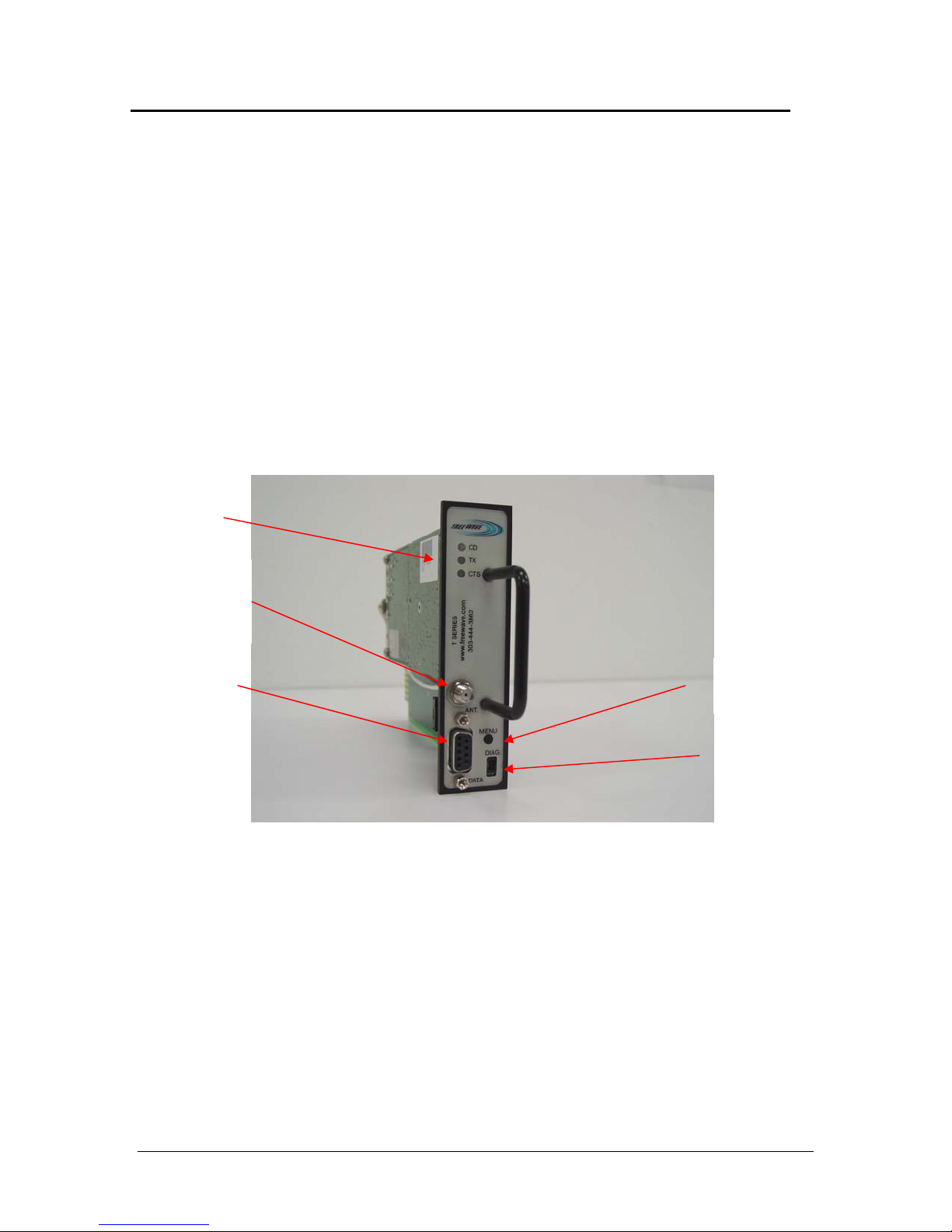
All data I/O and antenna connections are made to the radio’s front panel
connectors. See Figure 1.
LED status
indicators
Antenna connector
50 ohms type SMA
Reverse SMA on
T24
Serial port (Main)
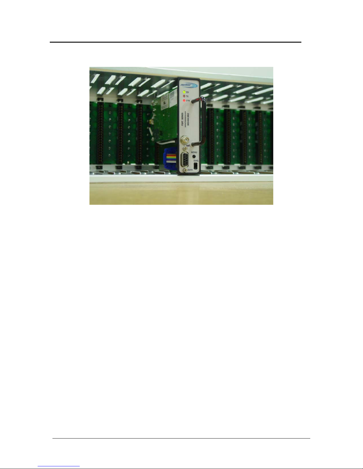
To operate a T-Series radio modem, insert the radio into a loop detector card
rack as shown in Figure 2. Make certain that the radio is fully seated in the card
slot. When a proper connection to the card rack has been made, one or more of
the LED status indicators will light. The LED indicators will show different
displays depending on how the radio is programmed when it is installed into the
card rack.
Figure 1. T-Series Front Panel
Setup button (press to
display menu)
Diagnostics and
programming port (Diag)
LAD0005AA Rev A
1
Page 2
FreeWave Technologies User Manual Addendum
T-Series Radio Modem
Figure 2. T-Series Installed In Loop Detector Rack
Connect antenna and data cables to the appropriate connectors on the T-Series
front panel. Note that the Model T24 radio uses a reverse-threaded SMA
connector.
Refer to the FreeWave FGR-Series user manual for instructions on setup and
operation of the T-Series radio modems. The T-Series products are fully
compatible with FreeWave’s FGR-Series 900 MHz radio modems or I-Series 2.4
GHz radio modems and may be used in networks with any of these products.
The T-Series radios will not communicate with radios that are not manufactured
by FreeWave Technologies.
LAD0005AA Rev A
2
 Loading...