

FreeWave MM2-M13 Series, MM2-M13-C, MM2-M13-C-SR, MM2-M13-LV-C, MM2-M13-T User's Reference Manual
...Page 1
MM2-M13 Serial Radios
MM2-M13-C MM2-M13-C-SR
MM2-M13-LV-C MM2-M13-LV-T
MM2-M13-T MM2-M13-T-DEVKIT
Covering Firmware 7.79
User & Reference Manual
Part Number: LUM0021AA
Revision: Mar-2018
Page 2

Safety Information
The products described in this manual can fail in a variety of modes due to misuse, age, or malfunction. Systems
with these products must be designed to prevent personal injury and property damage during product operation
and in the event of product failure.
Warning! Do not remove or insert cables while the circuit is live unless the area is known to be free
of ignition concentrations of flammable gasses or vapors.
FreeWave Technologies, Inc. warrants the FreeWave® MM2-M13 Serial Radio (Product) that you have
purchased against defects in materials and manufacturing for a period of two years from the date of shipment,
depending on model number. In the event of a Product failure due to materials or workmanship, FreeWave will,
at its discretion, repair or replace the Product. For evaluation of Warranty coverage, return the Product to
FreeWave upon receiving a Return Material Authorization (RMA). The replacement product will remain under
warranty for 90 days or the remainder of the original product warranty period, whichever is longer.
IN NO EVENT WILL FREEWAVE TECHNOLOGIES, INC., ITS SUPPLIERS, OR I TS LICENSORS BE LIABLE FOR ANY DAMAGES ARISING
FROM THE USE OF OR INABILITY TO USE THIS PRODUCT. THIS INCLUDES BUSINESS INTERRUPTION, LOSS OF BUSINESS
INFORMATION, INABILITY TO ACCESS OR SEND COMMUNICATION OR DATA, PERSONAL INJURY OR DAMAGE, OR OTHER LOSS
WHICH MAY ARISE FROM THE USE OF THIS PRODUCT. THE WARRANTY IS EXCLUSIVE AND ALL OTHER WARRANTIES EXPRESS
OR IMPLIED, INCLUDING BUT NOT LIMI TED TO ANY WARRANTIES OF MERCHANTABILITY OR FITNESS FOR A PARTICULAR USE
ARE EXPRESSLY DISCLAIMED.
FreeWave’s Warranty does not apply in the following circumstances:
1. If Product repair, adjustments, or parts replacements are required due to accident, neglect, or undue
physical, electrical, or electromagnetic stress.
2. If Product is used outside of FreeWave specifications as stated in the Product's data sheet.
3. If Product has been modified, repaired, or altered by Customer unless FreeWave specifically authorized
such alterations in each instance in writing.
FreeWave Technologies, Inc.
5395 Pearl Parkway, Suite 100
Boulder, CO 80301
303.381.9200
Toll Free: 1.866.923.6168
Fax: 303.786.9948
Copyright © 2018 by FreeWave Technologies, Inc.
All rights reserved.
www.freewave.com
Page 2 of 119 LUM0021AA Rev Mar-2018
This document is the property of FreeWave Technologies, Inc. and contains proprietary information owned by
FreeWave. This document cannot be reproduced in whole or in part by any means without written permission from
FreeWave Technologies, Inc.
Page 3

MM2-M13 Serial Radios: User & Reference Manual
Table Of Contents
Preface 7
1. Overview 9
2. Equipment 10
2.1. Included Equipment 10
2.1.1. User-supplied Equipment 10
2.2. Finding the Product Serial Number 10
3. Installation 11
3.1. Power Setup 12
3.2. Connections and Installation 13
3.2.1. Radio Setup Mode 14
3.2.2. Tera Term Activation 14
3.3. Choosing a Location for the Radio 17
4. Upgrading Serial Firmware Using a Direct Connection 18
5. Basic Radio Programming and Setup 21
5.1. Choosing Point-to-Point or Point-to-Multipoint Operation 22
5.1.1. Point-to-Point Network 22
5.1.2. Point-to-Multipoint Network 22
5.1.3. Examples of Data Communication Links 23
Point-to-Point Link 23
Point-to-Point Link with Repeater 23
Two Repeaters between the Master and Slave 24
Master Calls Slaves at Different Times 24
Standard Point-to-Multipoint Network 25
Point-to-Multipoint Network with a Multipoint Slave/Repeater 26
Standard TDMA Network 26
5.2. Define the Radio's Role in the Network and the Network Type 27
5.3. Establishing Communication with Instrumentation and Computers 30
5.3.1. Baud Rate 30
5.3.2. Data, Parity 30
5.3.3. Flow Control 31
5.3.4. Modbus RTU 31
5.3.5. RS422 / RS485 (Serial Interface) 32
5.3.6. Setup Port 33
5.3.7. Turn Off Delay 34
5.3.8. Turn On Delay 34
5.3.9. Use Break to Access Setup 34
5.4. Establishing Communication with Other Radios in the Network 35
5.4.1. Golden Settings 36
LUM0021AA Rev Mar-2018 Page 3 of 119
This document is the property of FreeWave Technologies, Inc. and contains proprietary information owned by
FreeWave. This document cannot be reproduced in whole or in part by any means without written permission from
FreeWave Technologies, Inc.
Page 4

5.5. Setting RF Transmission Characteristics 36
5.5.1. Frequency Key in 1.3GHz Radios 37
5.5.2. Frequency Zone (3) 38
5.5.3. High Noise (A) 40
5.5.4. Hop Freq Offset (2) 40
5.5.5. Hop Table Size (1) 40
5.5.6. Hop Table Version (0) 41
5.5.7. Lowpower Mode (9) 41
5.5.8. Max Packet Size (1) and Min Packet Size (2) 43
Minimum Packet Size Definition Table 43
Maximum Packet Size Definition with RF Date Rate of 2 43
Maximum Packet Size Definition with RF Date Rate of 3 44
5.5.9. MCU Speed (B) 45
5.5.10. Remote LED (C) 45
5.5.11. Retry Time Out (8) 45
5.5.12. RF Data Rate (4) 46
5.5.13. RF Xmit Power (5) 47
5.5.14. RTS to CTS (7) 47
5.5.15. Single Freq (4) 49
5.5.16. Slave Security (6) 49
5.5.17. Xmit Rate (3) 50
6. Configuring Point-to-MultiPoint Networks 51
6.1. Point-to-MultiPoint Network Characteristics 52
6.1.1. Golden Settings 52
6.1.2. Master-to-Slave Communications 52
6.1.3. Slave-to-Master Communications 52
6.2. Quick Start on a Point-to-Multipoint Network 53
6.3. Point-to-MultiPoint Operation LEDs 55
6.4. Overlapping Multipoint Networks 56
6.5. Establishing Communication with Other Radios in a Multipoint Network 56
6.5.1. Using the Network ID in Multipoint Networks 56
6.5.2. Using Call Book in Multipoint Networks 57
6.5.3. Programming Point-to-Multipoint Extended Call Book 58
6.6. Routing Communications through the Network 59
6.6.1. Assigning Subnet ID Values 59
Example 1: Subnet and Specific Path Communication 60
Example 2: Subnet and Communication Required through Repeaters 61
Example 3: Subnet and Optional Slave Communication 62
6.7. Setting Other Multipoint Parameters 63
6.7.1. 1 PPS Enable/Delay (9) 63
Page 4 of 119 LUM0021AA Rev Mar-2018
This document is the property of FreeWave Technologies, Inc. and contains proprietary information owned by
FreeWave. This document cannot be reproduced in whole or in part by any means without written permission from
FreeWave Technologies, Inc.
Page 5

MM2-M13 Serial Radios: User & Reference Manual
Setup 1PPS Enable/Delay 63
Calibrate a Slave Radio in 1PPS Enable/Delay Mode 63
6.7.2. Diagnostics (B) 64
6.7.3. DTR Connect (4) 64
6.7.4. Local Access (E) 65
6.7.5. Master Packet Repeat (1) 66
6.7.6. Master Packet Repeat in Multipoint Networks with Repeaters 67
6.7.7. Max Slave Retry (2) 67
6.7.8. MultiMasterSync (8) 67
6.7.9. Network ID (6) 68
6.7.10. Number Repeaters (0) 68
6.7.11. Radio ID (D) 69
6.7.12. Radio Name (G) 69
6.7.13. Repeater Frequency (5) 70
6.7.14. Retry Odds (3) 70
6.7.15. Slave/Repeater (A) 71
6.7.16. Subnet ID (C) 72
6.8. Conserving Power 73
6.8.1. Low Power Mode 74
7. Configuring Point-to-Point Networks 77
7.1. Quick Start on a Point-to-Point Network 77
7.2. Point-to-Point Operation LEDs 80
7.3. Using Call Book in Point-to-Point Networks 81
7.3.1. Programming Point-To-Point Extended Call Book to Use Three or Four Repeaters 82
8. Advanced Programming 83
8.1. Working with Parallel Repeaters 84
8.1.1. Repeaters Data Transmitted on the Same Frequency Key 84
8.1.2. Adding a Repeater to the Network 85
8.2. Setting and Changing Radio Passwords 86
8.2.1. Setting the Password 86
8.2.2. Changing a Password 86
8.2.3. Disable a Password 87
8.3. Enable and Set Up AES Encryption 87
8.3.1. Encryption Channel Key 88
8.3.2. Encryption Key 89
8.3.3. Encryption (Strength) 91
8.3.4. Troubleshooting AES Setup 91
8.4. Low Baud Rates 92
8.5. Multi-Master Synch 92
8.6. Time Divisible Multiple Access (TDMA) 92
LUM0021AA Rev Mar-2018 Page 5 of 119
This document is the property of FreeWave Technologies, Inc. and contains proprietary information owned by
FreeWave. This document cannot be reproduced in whole or in part by any means without written permission from
FreeWave Technologies, Inc.
Page 6

9. Viewing Radio Statistics 93
9.1. Antenna Reflected Power 94
9.2. Master-Slave Distance 94
9.3. Noise Level 94
9.4. Number of Disconnects 94
9.5. Radio Temperature 94
9.6. Rate % 95
9.7. Signal 95
9.8. Transmit Current (mA) 95
10. Troubleshooting 96
10.1. Troubleshooting Flowchart 99
11. MM2-M13 - Serial Radios Release Notes 100
11.1. Version 7.79 100
11.2. Version 7.78 102
11.3. Version 7.77 102
11.4. Version 7.70j 102
11.5. Version 7.70i (Initial Release) 102
12. Additional Radio Information 103
12.1. Operational RS422 and RS485 Information 103
12.1.1. RS485 Half Duplex Pin-Outs 104
12.2. RS232 Pin Assignments (DB-9) 104
12.3. Board Level Pinout 105
12.4. MM2-M13 Serial Radio Pinout 106
Appendix A: Technical Specifications 108
Appendix B: MM2-M13-C and -LV-C Mechanical Drawing 110
Appendix C: MM2-M13-T and -LV-T Mechanical Drawing 111
Appendix D: Factory Default Settings 112
Appendix E: Single Frequency Setting 114
Appendix F: FreeWave Legal Information 117
Page 6 of 119 LUM0021AA Rev Mar-2018
This document is the property of FreeWave Technologies, Inc. and contains proprietary information owned by
FreeWave. This document cannot be reproduced in whole or in part by any means without written permission from
FreeWave Technologies, Inc.
Page 7

MM2-M13 Serial Radios: User & Reference Manual
Preface
Contact FreeWave Technical Support
For up-to-date troubleshooting information, check the Support page at www.freewave.com.
FreeWave provides technical support Monday through Friday, 8:00 AM to 5:00 PM Mountain
Time (GMT -7).
l Call toll-free at 1.866.923.6168.
l In Colorado, call 303.381.9200.
l Contact us through e-mail at moreinfo@freewave.com.
Document Styles
This document uses these styles:
l Parameter setting text appears as: [Page=radioSettings]
l File names appear as: configuration.cfg.
l File paths appear as: C:\Program Files (x86)\FreeWave Technologies.
l User-entered text appears as: xxxxxxxxx.
Caution: Indicates a situation that MAY cause damage to personnel, the radio, data, or
network.
Example: Provides example information of the related text.
FREEWAVE Recommends: Identifies FreeWave recommendation information.
LUM0021AA Rev Mar-2018 Page 7 of 119
This document is the property of FreeWave Technologies, Inc. and contains proprietary information owned by
FreeWave. This document cannot be reproduced in whole or in part by any means without written permission from
FreeWave Technologies, Inc.
Page 8
Preface
<Parameter Name>
Setting Description
Default Setting: The factory default setting for the parameter.
Options: The options the parameter can be set to.
Terminal Menu: The menu path and field name to access the parameter using the terminal menus
available through the serial port.
Description: A description of what the parameter is and how it applies to the radio in the
network.
Important!: Provides crucial information relevant to the text or procedure.
Note: Emphasis of specific information relevant to the text or procedure.
Provides time saving or informative suggestions about using the product.
Warning! Indicates a situation that WILL cause damage to personnel, the radio, data, or
network.
Printing this Document
This document is set to print double-sided with a front cover and a back cover. Viewing this
document online with a PDF viewer, may show pages intentionally left blank to accommodate the
double-sided printing.
Documentation Feedback
Send comments or questions about this document's content to techpubs@freewave.com. In the
email, include the title of the document or the document's part number and revision letter (found in
the footer).
Parameter Preference
The Parameter Preference table describes the available parameters.
Page 8 of 119 LUM0021AA Rev Mar-2018
This document is the property of FreeWave Technologies, Inc. and contains proprietary information owned by
FreeWave. This document cannot be reproduced in whole or in part by any means without written permission from
FreeWave Technologies, Inc.
Page 9

MM2-M13 Serial Radios: User & Reference Manual
1. Overview
FreeWave serial radios are DCE (Data Communications Equipment) radios that operate in
virtually any environment where data communications occur. The radios act as data transmission
devices, duplicating data in either Point-to-Point or Point-To-Multipoint mode.
This document includes:
l A basic introduction to the radio and how to determine the mode you want to run it in.
l Examples of how FreeWave radios can exist in a network with other radios.
l How to access the setup parameters available on the radio.
l Basic radio programming and setup information that applies to all network types.
l Considerations and quick starts for network design, including charts of LED displays.
l Details about defining a Multipoint network including the use of subnet IDs to route
information through the network.
l Steps to view statistics about a radio's performance.
l Pinouts and mechanical drawings.
LUM0021AA Rev Mar-2018 Page 9 of 119
This document is the property of FreeWave Technologies, Inc. and contains proprietary information owned by
FreeWave. This document cannot be reproduced in whole or in part by any means without written permission from
FreeWave Technologies, Inc.
Page 10

MM2-M13 Serial Radios: User & Reference Manual
Included Equipment
Qty Description
1 MM2-M13 Serial Radio
2. Equipment
2.1. Included Equipment
This is the equipment included with the MM2-M13 Serial Radio device:
2.1.1. User-supplied Equipment
l DC power source
l Serial and power cable
2.2. Finding the Product Serial Number
Each FreeWave radio is assigned a unique serial number. When contacting FreeWave Technical
Support, this serial number is asked for from the radio you are calling about.
The serial number is three digits, followed by a hyphen and four digits (e.g., 111-1111) and is
printed on the FreeWave label on the radio.
LUM0021AA Rev Mar-2018 Page 10 of 119
This document is the property of FreeWave Technologies, Inc. and contains proprietary information owned by
FreeWave. This document cannot be reproduced in whole or in part by any means without written permission from
FreeWave Technologies, Inc.
Page 11

MM2-M13 Serial Radios: User & Reference Manual
3. Installation
l Power Setup (on page 12)
l Connections and Installation (on page 13)
l Radio Setup Mode (on page 14)
l Tera Term Activation (on page 14)
LUM0021AA Rev Mar-2018 Page 11 of 119
This document is the property of FreeWave Technologies, Inc. and contains proprietary information owned by
FreeWave. This document cannot be reproduced in whole or in part by any means without written permission from
FreeWave Technologies, Inc.
Page 12

3. Installation
3.1. Power Setup
Connect the MM2-M13 Serial Radio to a positive power supply with +8.0 to +30.0 VDC, typically
+12.0 VDC.
l The MM2-M13 Serial Radio is approved to operate with a positive power supply / input
voltage range of +8.0 to +30.0 VDC (+5 VDC LV models only).
l See the Technical Specifications (on page 108) for additional information.
FREEWAVE Recommends: For guaranteed performance, use between +8.0 to +30.0 VDC to
power the radio.
A dedicated power supply line is preferred.
The power supply used MUST provide more current than the amount of current drain listed in the
specifications for the product and voltage.
Warning! If the power supply line runs outside the enclosure, use electrostatic discharge
(ESD) protectors to protect the radio from electric shock and transient voltage suppressors
(TVS) to protect from an over-voltage situation.
Page 12 of 119 LUM0021AA Rev Mar-2018
This document is the property of FreeWave Technologies, Inc. and contains proprietary information owned by
FreeWave. This document cannot be reproduced in whole or in part by any means without written permission from
FreeWave Technologies, Inc.
Page 13
MM2-M13 Serial Radios: User & Reference Manual
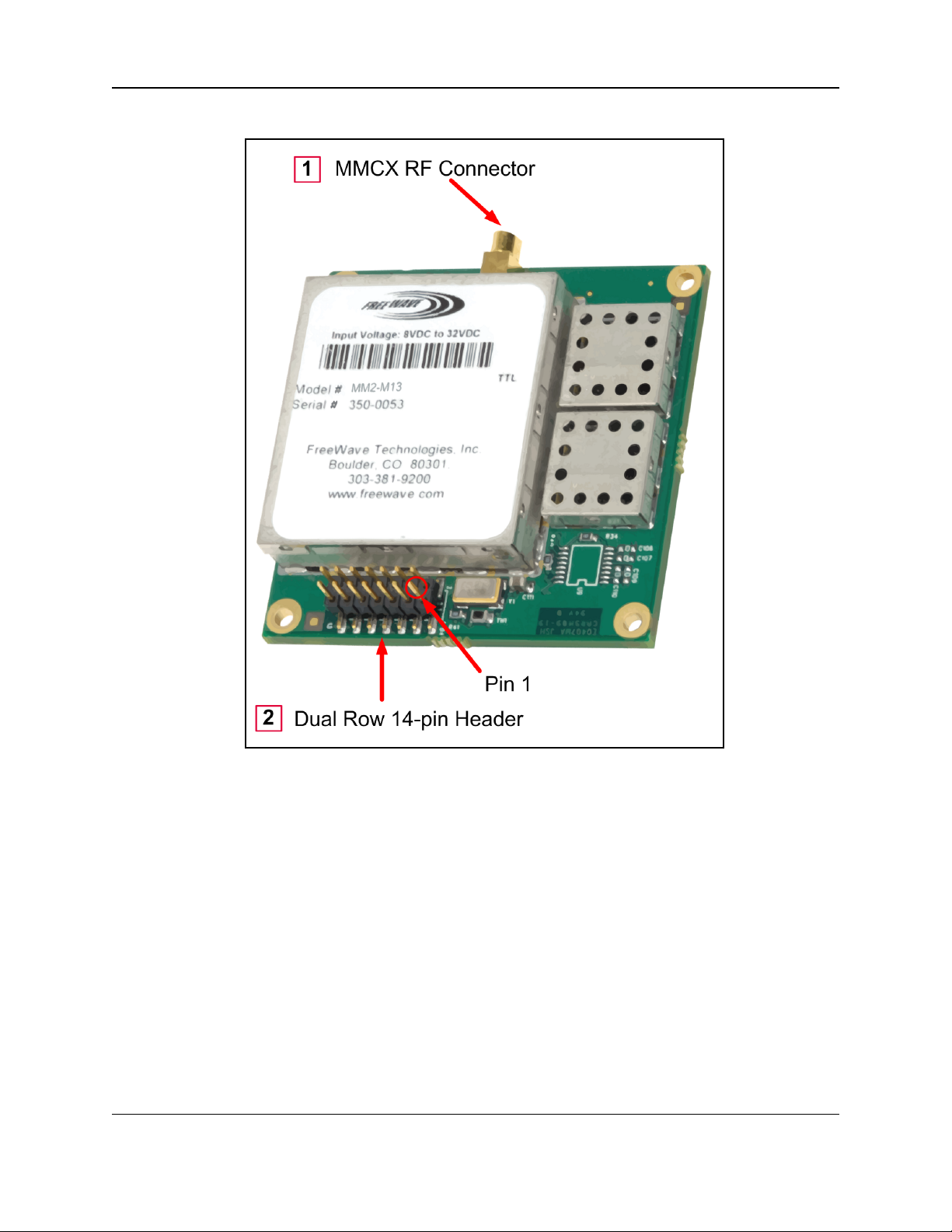
3.2. Connections and Installation
Figure 1: MM2-M13 Serial Radio Connections
LUM0021AA Rev Mar-2018 Page 13 of 119
This document is the property of FreeWave Technologies, Inc. and contains proprietary information owned by
FreeWave. This document cannot be reproduced in whole or in part by any means without written permission from
FreeWave Technologies, Inc.
Page 14
3. Installation
3.2.1. Radio Setup Mode
l To read the current settings from or to program a radio, the radio must be in Setup mode.
l When a radio is in Setup mode, all three LEDs appear solid green .
OEM boards may also enter Setup when Pin 2 on the 14-pin connector is grounded or when
using a break command.
Note: For Setup mode troubleshooting information, see Troubleshooting (on page 96).
3.2.2. Tera Term Activation
Note: This procedure is for a MM2-M13 Serial Radio interfaced to a computer.
If interfaced to a device other than a computer, some of these procedure steps may not be used.
Note: This procedure provides a Tera Term terminal connection to the MM2-M13 Serial Radio CLI.
Other terminal emulators (e.g., HyperTerminal, PuTTY) may be used.
The images in this procedure are for Windows® 7 and/or Firefox®.
The dialog boxes and windows appear differently on each computer.
1. On the computer connected to the MM2-M13 Serial Radio, open a terminal program (e.g.,
Tera Term http://ttssh2.osdn.jp/).
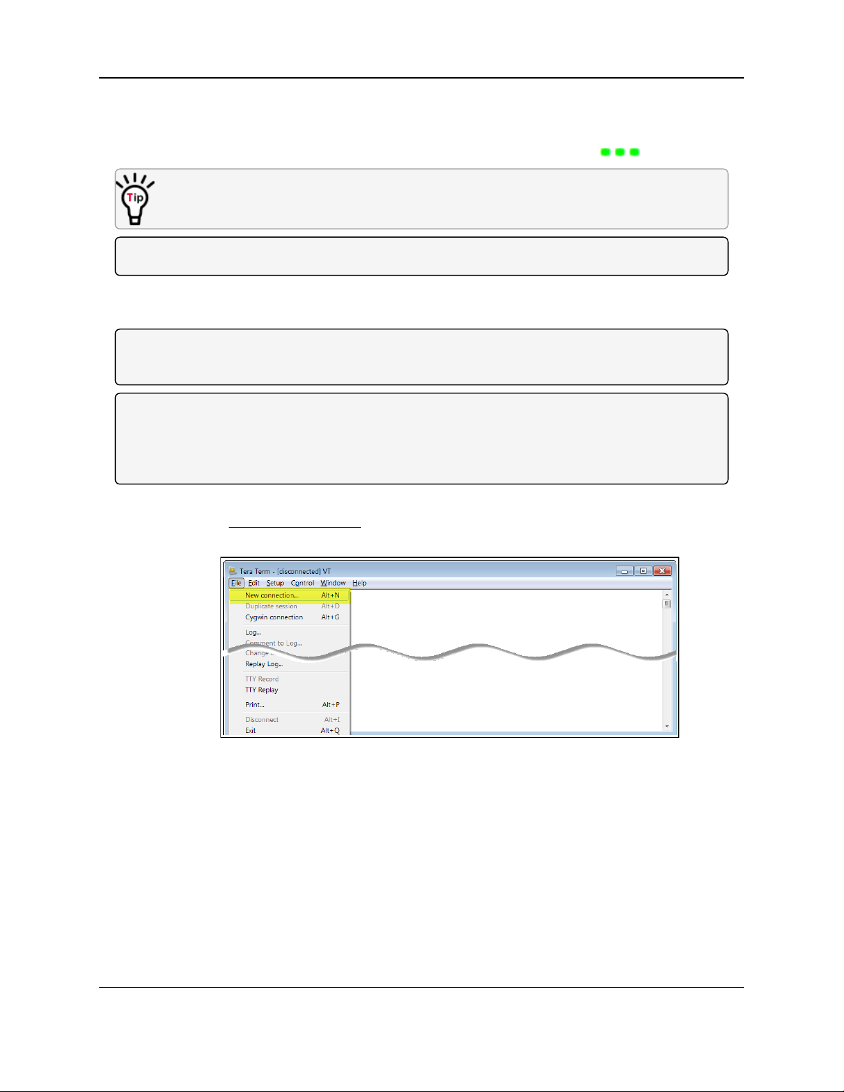
2. In Tera Term, on the File menu, select New Connection.
Figure 2: File menu > New Connection
The Tera Term New Connection dialog box opens.
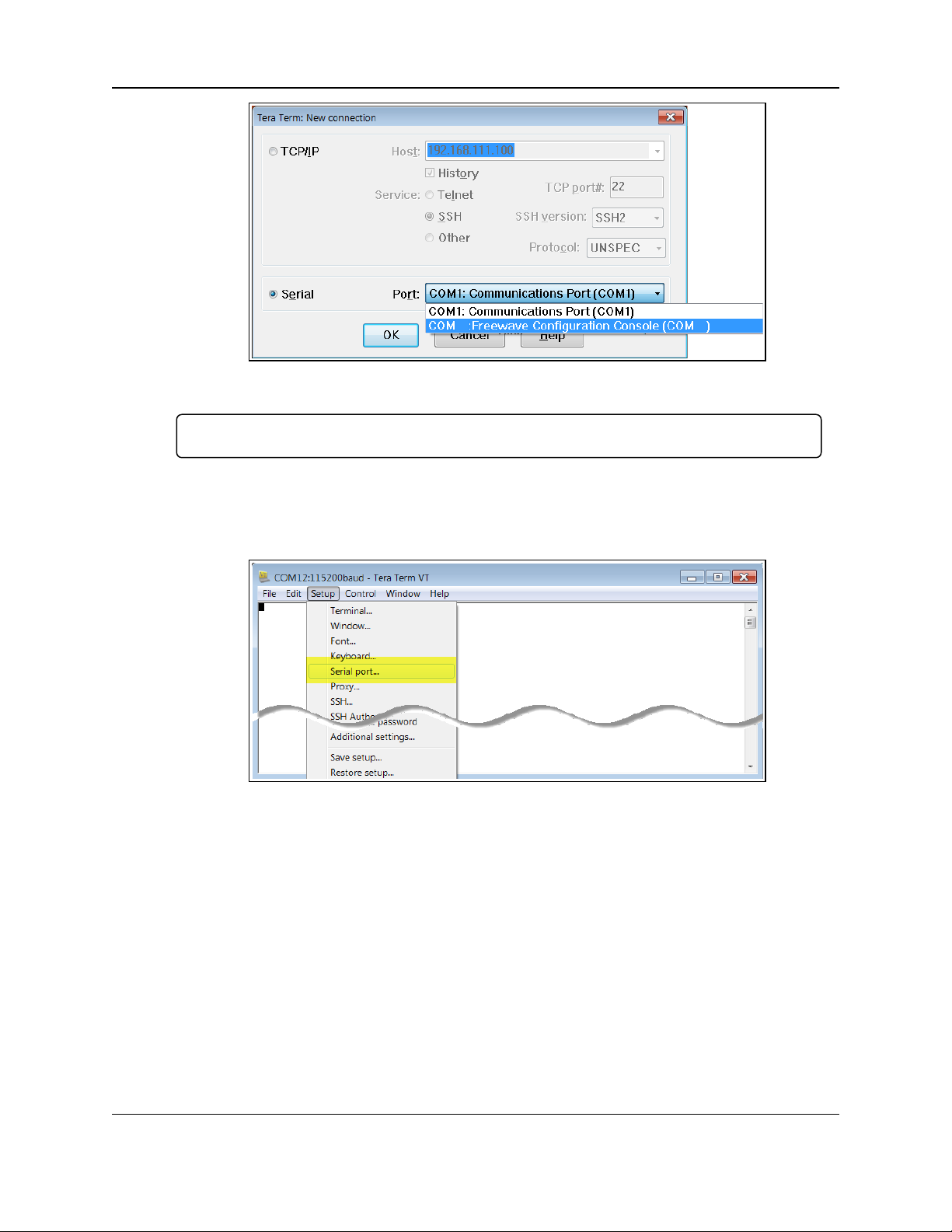
3. Click the Port list box arrow and select the COM port the MM2-M13 Serial Radio device is
connected to.
Page 14 of 119 LUM0021AA Rev Mar-2018
This document is the property of FreeWave Technologies, Inc. and contains proprietary information owned by
FreeWave. This document cannot be reproduced in whole or in part by any means without written permission from
FreeWave Technologies, Inc.
Page 15
MM2-M13 Serial Radios: User & Reference Manual
Figure 3: Select the COM port
Important!: The Port assignment varies from computer to computer.
4. Click OK to save the changes and close the dialog box.
The Tera Term window shows the connected COM port and Baud rate in the title bar of the
window.
5. In the Tera Term window, click the Setup menu and select Serial Port.
Figure 4: Serial menu > Setup Port
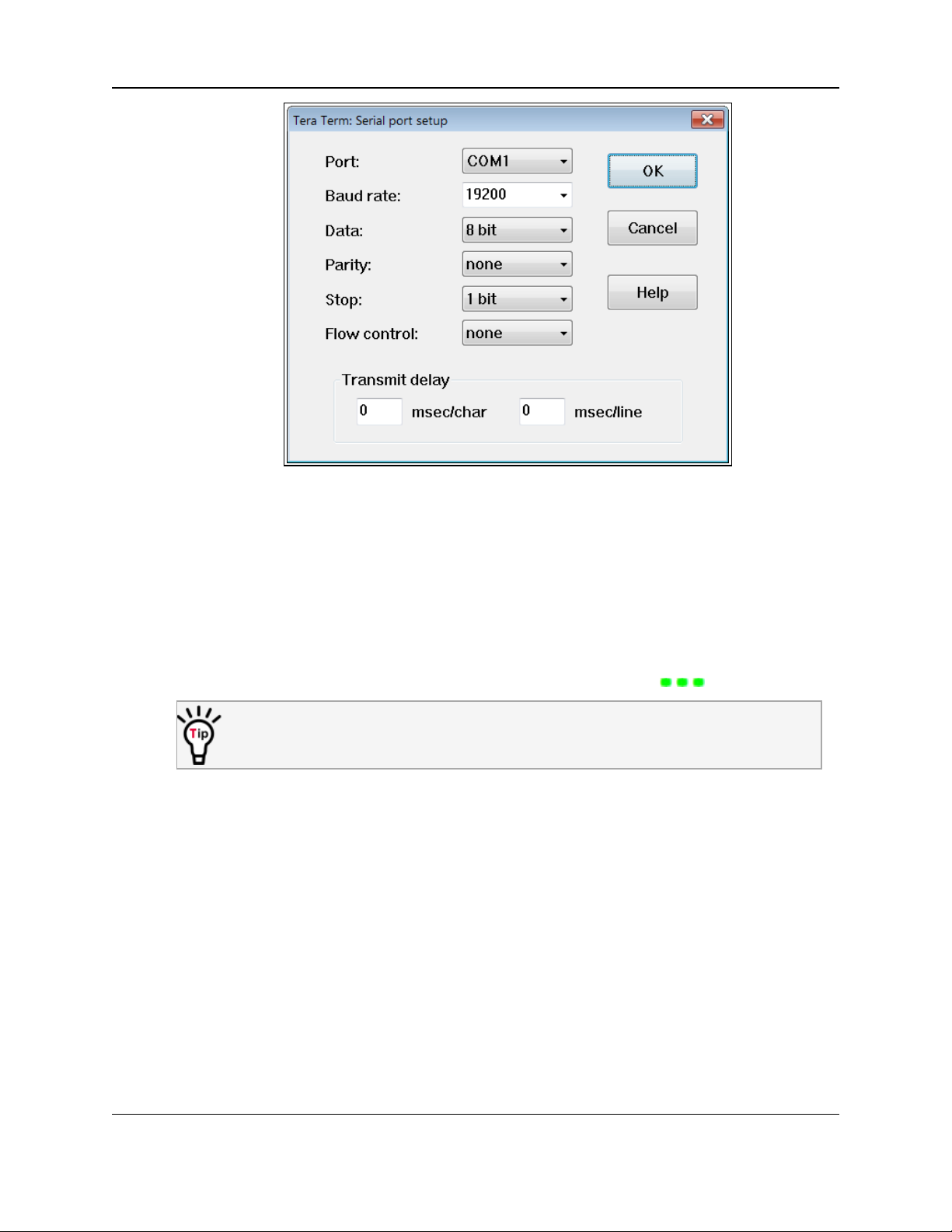
The Tera Term: Serial Port Setup dialog box opens with the default MM2-M13 Serial
Radio settings.
6. Verify, and change if required, the Tera Term serial port settings (except the Port setting) of
the connected MM2-M13 Serial Radio so the settings are the same as the defaults shown in
Figure 5.
LUM0021AA Rev Mar-2018 Page 15 of 119
This document is the property of FreeWave Technologies, Inc. and contains proprietary information owned by
FreeWave. This document cannot be reproduced in whole or in part by any means without written permission from
FreeWave Technologies, Inc.
Page 16
3. Installation
Figure 5: Tera Term: Serial Port Setup dialog box with Default Settings
7. Verify the COM port settings are:
Baud Rate: 19200
Data: 8 bit
Parity: none
Stop: 1 bit
8. Click OK to save the changes and close the dialog box.
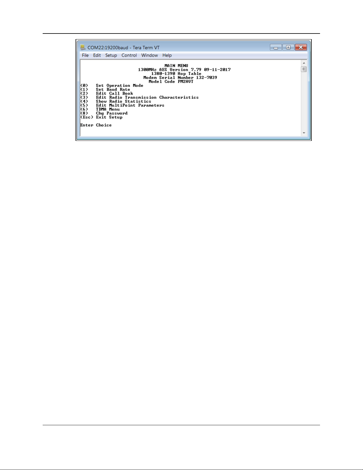
9. 9. Place the radio in Setup mode.
When a radio is in Setup mode, all three LEDs appear solid green .
OEM boards may also enter Setup when Pin 2 on the 14-pin connector is grounded or
when using a break command.
The Tera Term window refreshes showing the MM2-M13 Serial Radio default Menu
Options. (Figure 6)
Page 16 of 119 LUM0021AA Rev Mar-2018
This document is the property of FreeWave Technologies, Inc. and contains proprietary information owned by
FreeWave. This document cannot be reproduced in whole or in part by any means without written permission from
FreeWave Technologies, Inc.
Page 17
MM2-M13 Serial Radios: User & Reference Manual
Figure 6: The MM2-M13 Serial Radio Default Menu Options
10. Continue with: Upgrading Serial Firmware Using a Direct Connection (on page 18)
3.3. Choosing a Location for the Radio
When embedding a radio, proper shielding form other electronics and radiated signals should be
accounted for to ensure that they do not interfere with the performance of the radio or that the
radio does not interfere with the performance of the other electronic devices.
LUM0021AA Rev Mar-2018 Page 17 of 119
This document is the property of FreeWave Technologies, Inc. and contains proprietary information owned by
FreeWave. This document cannot be reproduced in whole or in part by any means without written permission from
FreeWave Technologies, Inc.
Page 18

MM2-M13 Serial Radios: User & Reference Manual
4. Upgrading Serial Firmware Using a Direct Connection
This is a firmware upgrade with a direct connection using the firmware executable file (.exe).
Note: Contact FreeWave Technical Support (on page 7) to get the latest firmware upgrade file.
l Firmware update files are also available from FreeWave Technical Support.
l For information about upgrading firmware over the air, see Application Note #5440
(available at http://support.freewave.com/).
l Registration is required to use this login.
FREEWAVE Recommends: Use USB-to-serial cables that include the FTDI Chip Set to shorten
the upgrade time.
This inclusion is listed on the cable's packaging.
For more information, see the Application Note #5471, Optimizing Firmware Upgrade Speed
While Using a USB-Serial Adaptor available at http://support.freewave.com/.
Registration is required to use this login.
LUM0021AA Rev Mar-2018 Page 18 of 119
This document is the property of FreeWave Technologies, Inc. and contains proprietary information owned by
FreeWave. This document cannot be reproduced in whole or in part by any means without written permission from
FreeWave Technologies, Inc.
Page 19
4. Upgrading Serial Firmware Using a Direct Connection
Procedure
Important!: Prior to starting the installation process, verify the Diagnostics parameter in the
MultiPoint parameters menu is set to 0.
1. Contact FreeWave Technical Support (on page 7) to get the latest firmware upgrade file.
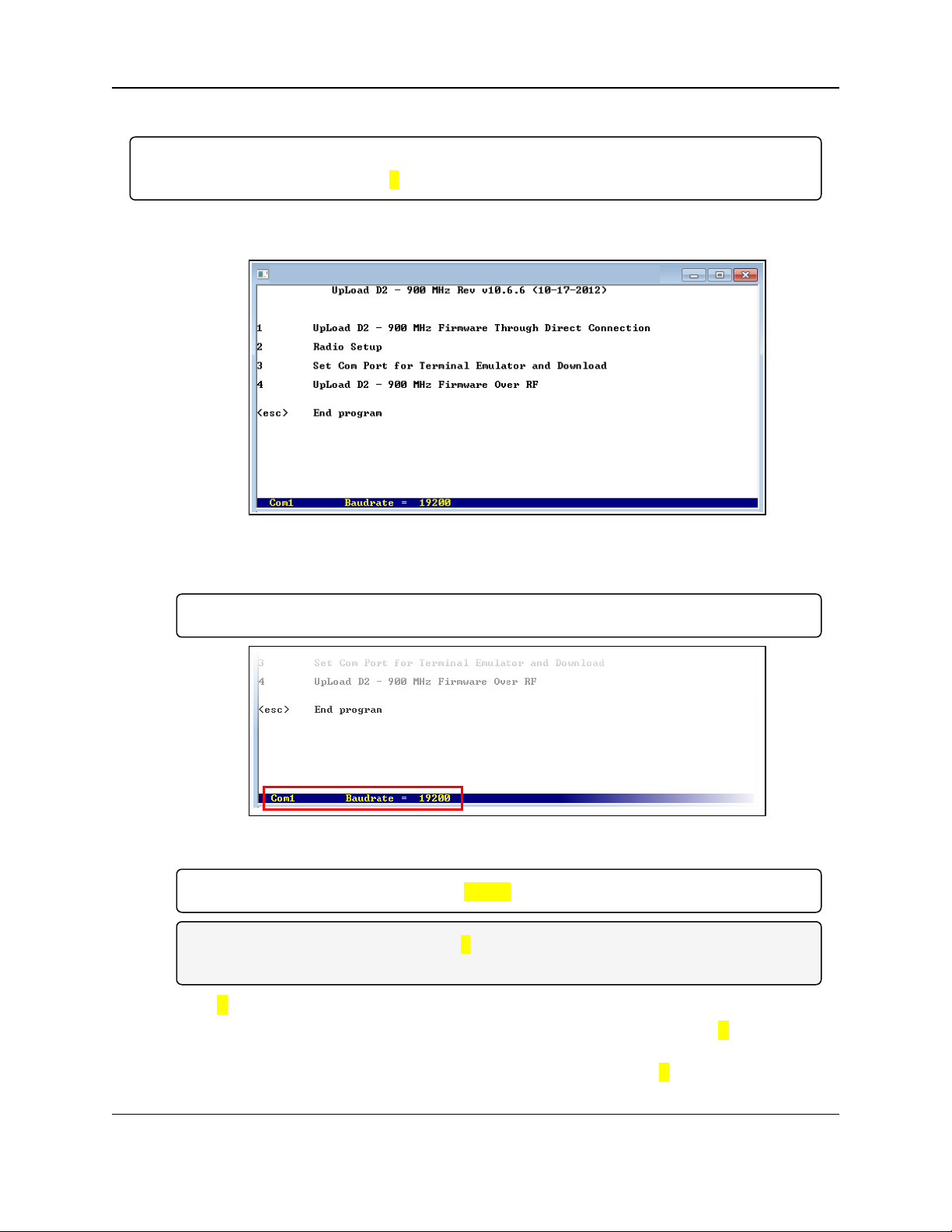
2. With the radio connected to the computer, double-click the .exe file to launch the upload file.
Figure 7: Upload window
3. Verify the COM port settings match the COM port the radio is connected to.
Important!: This program does not work with COM port numbers higher than 2.
Figure 8: COM port settings
Important!: The baud rate must be set to 19200.
Note: If the settings do not match, press 3 in the utility, update the settings, and return to the
main menu.
4. Type 1 to begin the upgrade process.
5. If the radio is connected to the computer using a diagnostics cable, enter Y at the Enter Y
for Diag Port prompt and press <Enter>.
If the radio is connected to the computer using a data cable, enter N and press <Enter>.
Page 19 of 119 LUM0021AA Rev Mar-2018
This document is the property of FreeWave Technologies, Inc. and contains proprietary information owned by
FreeWave. This document cannot be reproduced in whole or in part by any means without written permission from
FreeWave Technologies, Inc.
Page 20
MM2-M13 Serial Radios: User & Reference Manual
6. When all three LEDs on the radio are solid green ( ), at the Radio in Setup prompt,
type Y and press <Enter>.
Important!: If all three LEDs are NOT solid green, the radio is NOT in Setup mode.
Do one of the following to enter Setup mode:
Enclosed models: press the Setup button on the back of the device.
Board-level models using a data cable, press the Setup button on the cable.
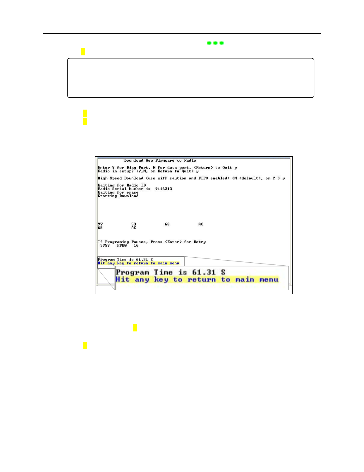
7. At the High Speed Download prompt,
Type Y if using the Diagnostic port or
Type N if fusing the Data port and press <Enter>.
The upgrade process starts.
If the process pauses before it is complete, press <Enter> to restart the process.
When the utility shows the Program Time, the process is complete.
Figure 9: Program Time
8. Press any key to return the main menu.
9. At the main menu, type 2 and place the radio in Setup mode.
The new firmware version number appears at the top of the Setup main menu.
10. Type Q to return to the utility’s main menu.
Press <Esc> to exit.
LUM0021AA Rev Mar-2018 Page 20 of 119
This document is the property of FreeWave Technologies, Inc. and contains proprietary information owned by
FreeWave. This document cannot be reproduced in whole or in part by any means without written permission from
FreeWave Technologies, Inc.
Page 21

MM2-M13 Serial Radios: User & Reference Manual
5. Basic Radio Programming and Setup
When the network is setup, either as a Point-to-MultiPoint or a Point-to-Point network, the
process for setting up and programming a radio is the same. This section describes the aspects of
programming and setting up a radio.
l Define the Radio's Role in the Network and the Network Type (on page 27)
l Establishing Communication with Instrumentation and Computers (on page 30)
l Establishing Communication with Other Radios in the Network (on page 35)
l Setting RF Transmission Characteristics (on page 36)
LUM0021AA Rev Mar-2018 Page 21 of 119
This document is the property of FreeWave Technologies, Inc. and contains proprietary information owned by
FreeWave. This document cannot be reproduced in whole or in part by any means without written permission from
FreeWave Technologies, Inc.
Page 22

5. Basic Radio Programming and Setup
5.1. Choosing Point-to-Point or Point-to-Multipoint Operation
5.1.1. Point-to-Point Network
A Point-to-Point network is best when the network has one Master and one Slave radio.
l A maximum of four Repeaters can be added to extend the reach of the network.
l All packets are acknowledged, whether sent from the Master to the Slave or from the Slave
to the Master.
l Adding Repeaters to a network cuts the data throughput by 50% and decreases overall
network capacity by 50%.
5.1.2. Point-to-Multipoint Network
In a Point-to-Multipoint network (also referred to as Multipoint network) the Master radio is able to
simultaneously communicate with numerous Slave radios.
l In its simplest form, a Multipoint network functions with the Master broadcasting its
messages to all Slave radios.
l The number of times outbound packets from the Master or Repeater to the Slave or other
Repeaters are sent is determined by the user.
l The receiving radio, Slave or Repeater, accepts the first packet received that passes the
32-bit CRC.
l Packets are not acknowledged by the receiving radio, Slave or Repeater.
l When granted by the Master, the Slave radios respond to the Master when given data by
the device connected to the Data port.
l All packets sent are acknowledged or retransmitted until they are acknowledged.
l The number of times a packet is sent to the Master is determined by the user.
l The network can be extended with as many Repeaters as is required.
l Adding Repeaters to a network cuts the data throughput by 50% and decreases overall
network capacity by 50%.
Traditionally, a Multipoint network is used where data is collected from many devices and reported
back to one central site. The architecture of this network is different from Point-to-Point
applications. These parameters influence the number of radios that can exist in a Multipoint
network:
l Data Block Size. The longer the data blocks, the fewer number of deployed Slave radios
can exist in the network.
l Baud Rate. The data rate between the radio and the device to which it is connected could
limit the amount of data and the number of radios that can exist in a network.
l Contention: The amount of contention between Slave radios. Polled Slave radios
versus vs. timed Slave radios.
l Repeaters. Adding Repeaters to a network cuts the data throughput by 50% and
decreases overall network capacity by 50%.
Page 22 of 119 LUM0021AA Rev Mar-2018
This document is the property of FreeWave Technologies, Inc. and contains proprietary information owned by
FreeWave. This document cannot be reproduced in whole or in part by any means without written permission from
FreeWave Technologies, Inc.
Page 23
MM2-M13 Serial Radios: User & Reference Manual
Example: If the network polls once a day to retrieve sparse data, several hundred Slave radios could
be configured to a single Master.
However, if each Slave transmits larger amounts of data or data more frequently, fewer Slave radios
can link to the Master while receiving the same network performance. When larger amounts of data
are sent more frequently, the overall network bandwidth is closer to capacity with fewerSlave radios.
5.1.3. Examples of Data Communication Links
FreeWave radios versatility allows data communication links to be established using a variety of
different configurations.
l Point-to-Point Link (on page 23)
l Point-to-Point Link with Repeater (on page 23)
l Two Repeaters between the Master and Slave (on page 24)
l Master Calls Slaves at Different Times (on page 24)
l Standard Point-to-Multipoint Network (on page 25)
l Point-to-Multipoint Network with a Multipoint Slave/Repeater (on page 26)
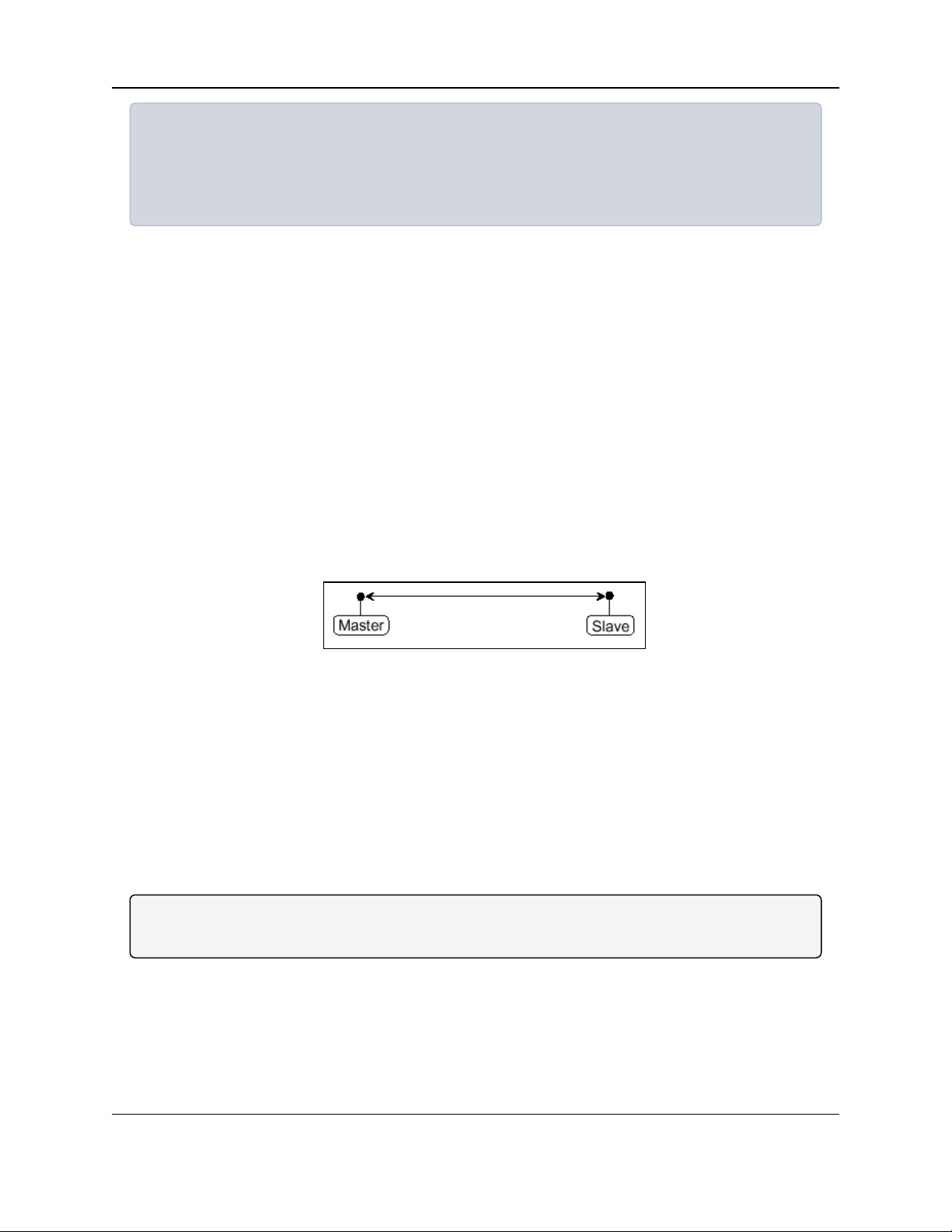
Point-to-Point Link
Figure 10 shows the most common and straightforward link, a Master communicating to a Slave in
a Point-to-Point link.
Figure 10: Point-to-Point Link
Point-to-Point Link with Repeater
Figure 11 shows how a link might be set up using a repeater.
l If a Repeater is located on a hilltop or other elevated structure, it can enhance the link from
the Master to the Slave.
l In this configuration, it is desirable to use an Omni-directional antenna at the Repeater.
l Yagi antennas may be used at both the Master and Slave radios to increase the range of
the link.
Note: Adding Repeaters to a network cuts the data throughput by 50% and decreases overall
network capacity by 50%.
LUM0021AA Rev Mar-2018 Page 23 of 119
This document is the property of FreeWave Technologies, Inc. and contains proprietary information owned by
FreeWave. This document cannot be reproduced in whole or in part by any means without written permission from
FreeWave Technologies, Inc.
Page 24
5. Basic Radio Programming and Setup
Figure 11: Point-to-Point Link with Repeater
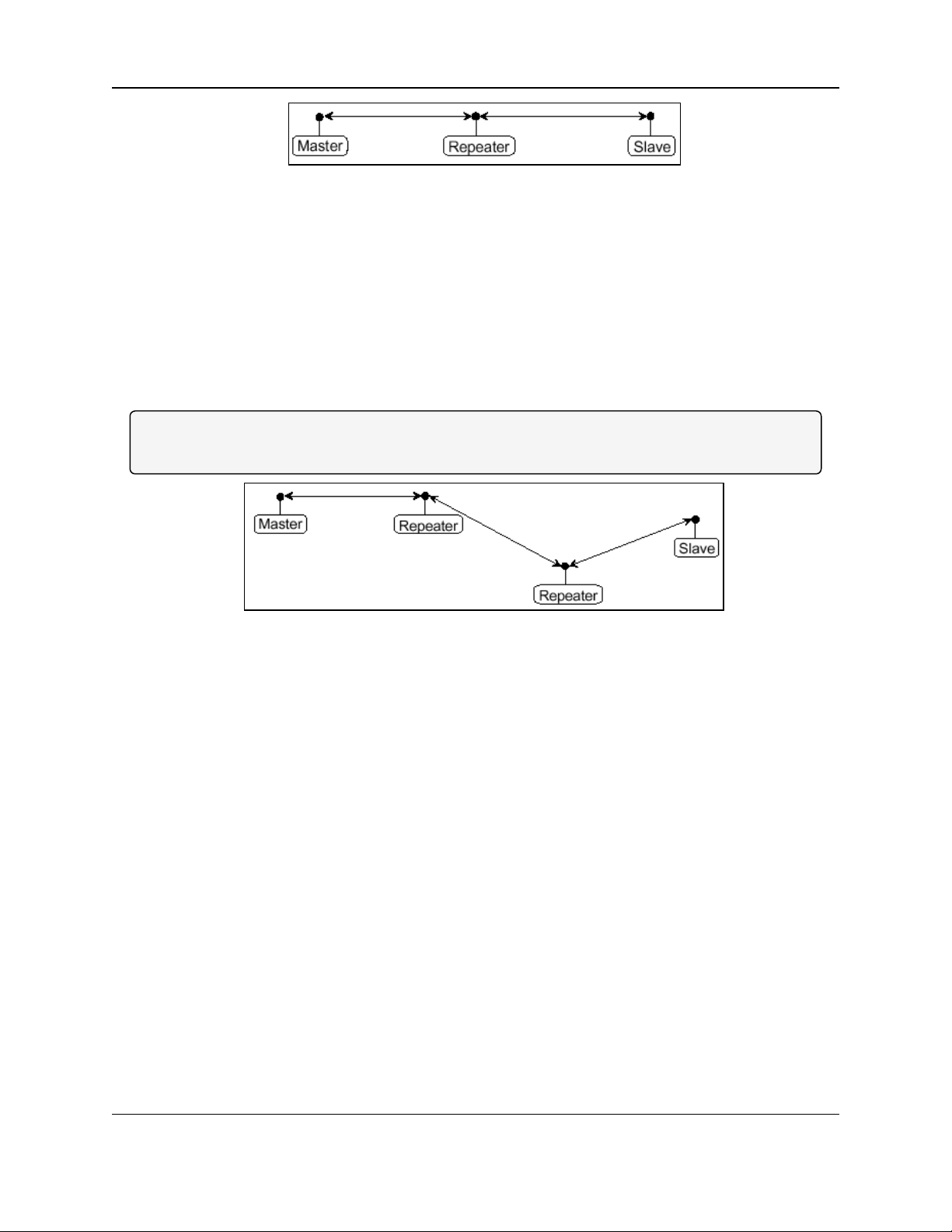
Two Repeaters between the Master and Slave
Figure 12 shows a link with two repeaters between the Master and Slave.
l With two Repeaters more flexibility in getting around obstacles and greater total range is
possible.
l In this configuration, it is desirable to use an Omni-directional antenna at the Repeater.
l Yagi antennas may be used at both the Master and Slave radios to increase the range of
the link.
Note: When two Repeaters are used, no further degradation in the data throughput of the link is
experienced.
Figure 12: Two Repeaters between the Master and Slave
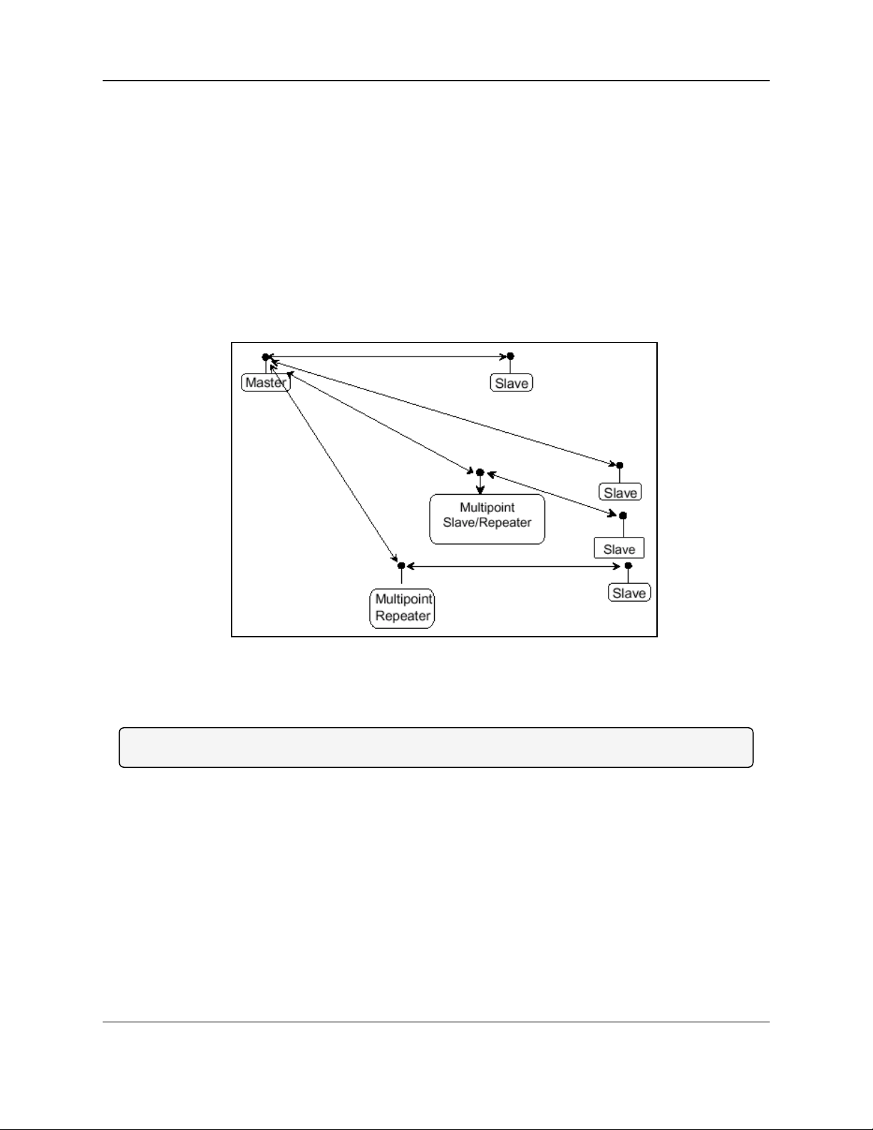
Master Calls Slaves at Different Times
Figure 13 shows a configuration where a Master routinely calls a number of Slaves at different
times.
l The Master is communicating with a radio designated as a Slave/Repeater that is
connected to a remote device.
l Since this device is placed in an elevated location, the radio can also be used as a repeater
when it is not used as a Slave.
l At any time the Master can call any of the Slaves, establish a connection, and send and
receive data.
Page 24 of 119 LUM0021AA Rev Mar-2018
This document is the property of FreeWave Technologies, Inc. and contains proprietary information owned by
FreeWave. This document cannot be reproduced in whole or in part by any means without written permission from
FreeWave Technologies, Inc.
Page 25
MM2-M13 Serial Radios: User & Reference Manual
Figure 13: Master Calls Slaves at Different Times
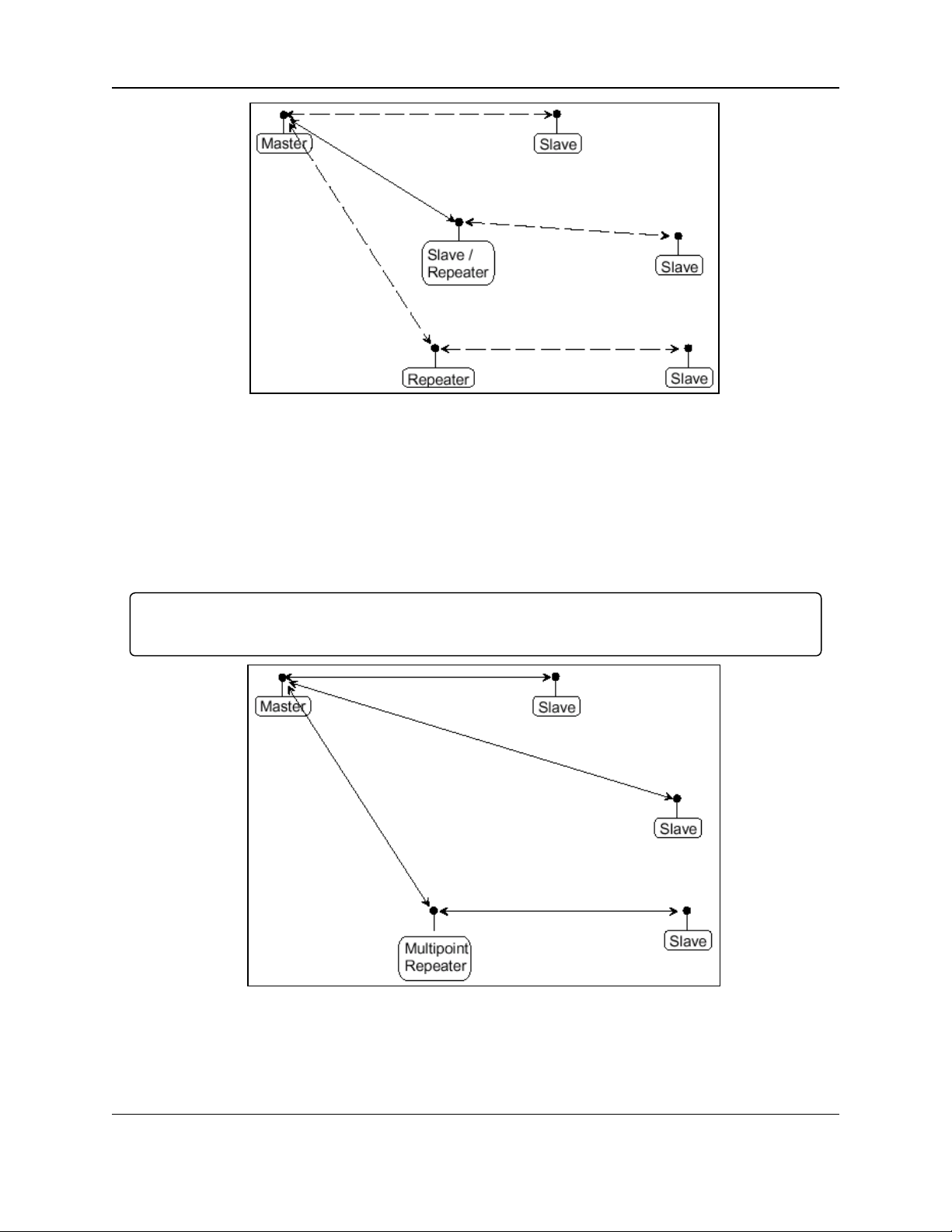
Standard Point-to-Multipoint Network
Figure 14 shows a standard Point-to-Multipoint network.
l From the Master, data is broadcast to all three Slaves, one of which receives it through a
Multipoint Repeater.
l The data is sent out of the serial port of each of the three Slaves.
Important!: The end device should be configured to interpret the serial message and act on it if
necessary.
Figure 14: Standard Point-to-Multipoint Network
LUM0021AA Rev Mar-2018 Page 25 of 119
This document is the property of FreeWave Technologies, Inc. and contains proprietary information owned by
FreeWave. This document cannot be reproduced in whole or in part by any means without written permission from
FreeWave Technologies, Inc.
Page 26
5. Basic Radio Programming and Setup
Point-to-Multipoint Network with a Multipoint Slave/Repeater
Figure 15 shows a Point-to-Multipoint network that uses one of the sites as a Slave/Repeater.
l This network functions in the same manner as a standard Multipoint network with
Repeaters.
l However, the number of radios can be reduced with the use of the Multipoint Slave feature.
l The Multipoint Slave allows communication to a device connected locally to the Multipoint
Slave’s serial port while also acting as a Repeater to pass messages between the Master
and a Slave.
l When compared to the Multipoint Repeater, the Multipoint Slave can only pass messages
between the Master and the Slave.
l It is not capable of passing messages to a device locally connected to its serial port.
Figure 15: Point-to-Multipoint Network with a Multipoint Slave
Standard TDMA Network
Note: TDMA is an option available for the MM2-M13 Serial Radio.
l A standard TDMA network requires a Master and Slave.
l Dedicated time slots are allocated to the Master and each of the Slaves guaranteeing
specific transmission slots.
l Slaves can be configured to communicate directly with other Slave.
Page 26 of 119 LUM0021AA Rev Mar-2018
This document is the property of FreeWave Technologies, Inc. and contains proprietary information owned by
FreeWave. This document cannot be reproduced in whole or in part by any means without written permission from
FreeWave Technologies, Inc.
Page 27
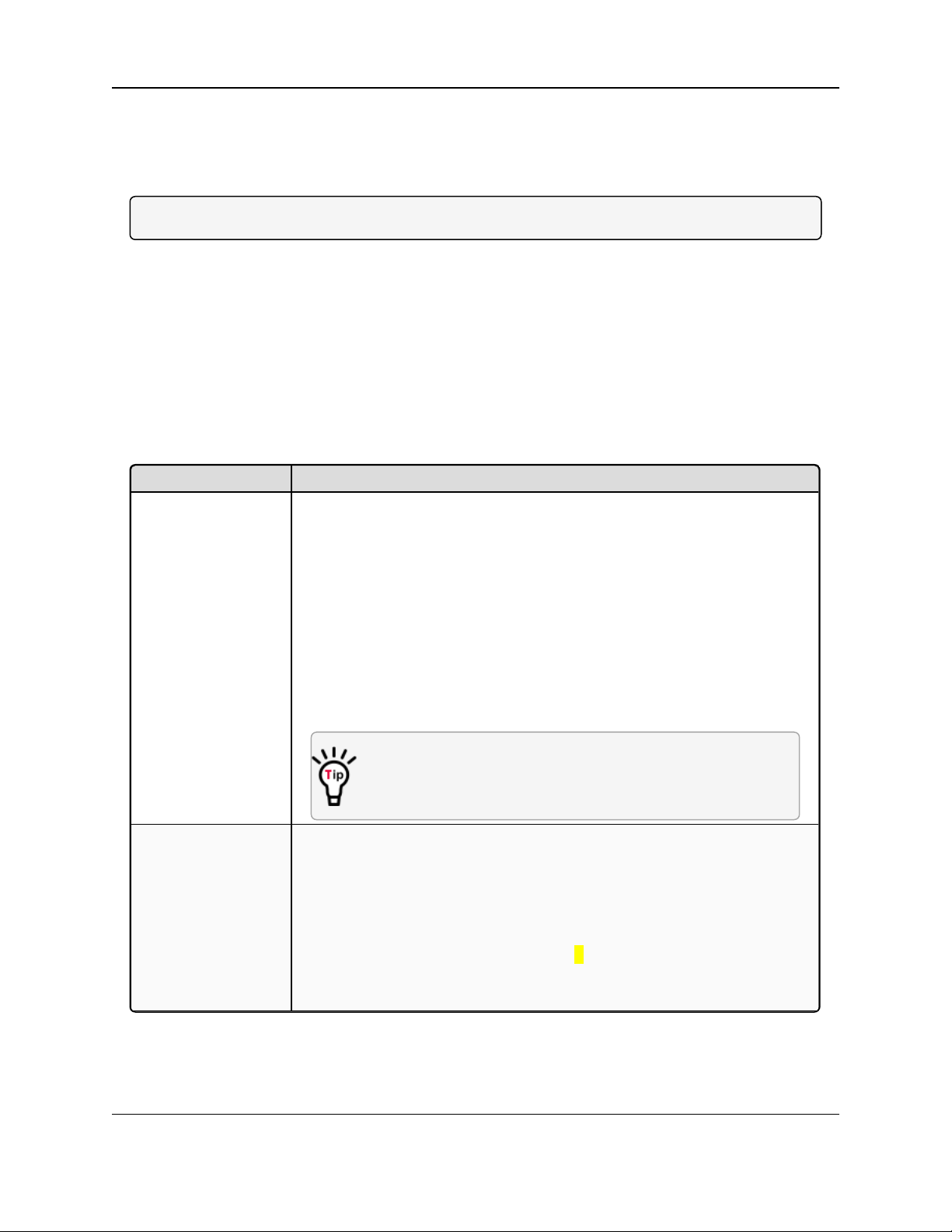
MM2-M13 Serial Radios: User & Reference Manual
Operation Mode Description
Point-to-Point Master
(0)
This mode designates the radio as the Master in Point-to-Point mode. The
Master may call any or all Slaves designated in its Call Book.
In Point-to-Point mode the Master determines the setting used for most of the
transmission characteristics, regardless of the settings in the Slaves and/or
Repeaters.
The settings NOT determined by the Master are:
l Transmit Power
l Slave Security
l Retry Time Out
l Hop Table settings
A quick method of identifying a Master is to power the radio.
Prior to establishing a link with a Slave, all three of the LEDs on
the Master are solid red.
Point-to-Point Slave
(1)
This mode designates the radio as a Slave in Point-to-Point mode.
l The Slave communicates with any Master in its Call Book either directly
or through a maximum of four Repeaters.
l When functioning as a Slave, the Entry to Call feature in the radio’s Call
Book is NOT operational.
l Set the Slave Security parameter to 1 to bypass the Call Book in the
Slave.
l For more information, see Slave Security (6) (on page 49).
5.2. Define the Radio's Role in the Network and the Network Type
On the Operation Mode menu, use the Modem Mode field to set the Modem Mode.
Note: These settings are available in the Operation Mode menu in the terminal interface.
The Operation Mode option designates the method FreeWave radios use to communicate with
each other. FreeWave radios operate in a Master to Slave configuration. Before the radios can
operate together, they must be set up to properly communicate.
In a Point-to-Point configuration, Master or Slave mode may be used on either end of the
communication link without performance degradation.
l When setting up the radio, remember that a number of parameters are controlled by the
settings in the Master.
l Therefore, deploying the Master on the communications end where it will be easier to
access is advised, but not necessary.
LUM0021AA Rev Mar-2018 Page 27 of 119
This document is the property of FreeWave Technologies, Inc. and contains proprietary information owned by
FreeWave. This document cannot be reproduced in whole or in part by any means without written permission from
FreeWave Technologies, Inc.
Page 28

5. Basic Radio Programming and Setup
Operation Mode Description
Point–to-MultiPoint
Master (2)
This mode designates the radio as a Master in MultiPoint mode.
l This mode allows one Master radio to communicate simultaneously with
numerous Slaves and Repeaters.
l A Point-to-MultiPoint Master communicates only with other radios
designated as Point-to-MultiPoint Slaves or Point-to-MultiPoint
Repeaters.
Point-to-MultiPoint
Slave (3)
This mode designates the radio as a Slave in MultiPoint mode.
l This mode allows the Slave to communicate with a MultiPoint Master.
l The Slave may communicate with its Master through one or more
Repeaters.
Point-to-Point
Slave/Repeater (4)
This mode designates the radio to act as EITHER a Slave or Repeater,
depending on the instructions from the Master.
l The radio cannot act as both a Slave and a Repeater at the same time.
l True Slave / Repeater functionality is only available in a MultiPoint mode.
l Point-to-Point Slave / Repeaters have no security features.
l When a radio is designated a Point-to-Point Slave / Repeater, it allows
any Master to use it as a Repeater.
Point-to-Point
Repeater (5)
FreeWave allows the use of a maximum of four Repeaters in a Point-to-Point
communications link, significantly extending the operating range.
l When designated as a Repeater, a radio behaves as a pass-through link.
l All settings for the Call Book, Baud Rates, and transmission
characteristics are disabled.
l A Repeater connects with any Master that calls it.
l The Repeater must be set up properly in the Master's Call Book.
Point-to-Point
Slave/Master
Switchable (6)
Mode 6 allows the radio to be controlled entirely through software commands.
l A number of key parameters in the FreeWave user interface may be
changed either directly using a program such as Windows® Terminal or
through the use of script files.
l Additionally, when the Point-to-Point Slave/Master Switchable option
is selected and the radio is not calling a Slave, it functions as a Slave and
accepts any appropriate calls from other radios.
Note: For more information, see Application Note #5476, Mode 6
(available at http://support.freewave.com/).
Point-to-MultiPoint
Repeater (7)
This option allows the radio to operate as a Repeater in a MultiPoint network.
l As many Repeaters as necessary are allowed in a MultiPoint network.
l If the Repeater is to act as a Slave / Repeater, set the Slave Repeater
parameter in the MultiPoint Parameters menu to Enabled.
FreeWave. This document cannot be reproduced in whole or in part by any means without written permission from
Page 28 of 119 LUM0021AA Rev Mar-2018
This document is the property of FreeWave Technologies, Inc. and contains proprietary information owned by
FreeWave Technologies, Inc.
Page 29

MM2-M13 Serial Radios: User & Reference Manual
Operation Mode Description
Ethernet Options (F)
Note: This menu is only used for Ethernet radios.
Although this menu is included here, it is not used in the MM2-M13
Serial Radio.
LUM0021AA Rev Mar-2018 Page 29 of 119
This document is the property of FreeWave Technologies, Inc. and contains proprietary information owned by
FreeWave. This document cannot be reproduced in whole or in part by any means without written permission from
FreeWave Technologies, Inc.
Page 30
5. Basic Radio Programming and Setup
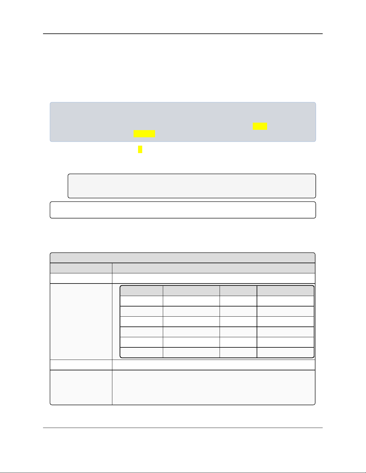
Data, Parity
Setting Description
Default Setting: 0 (8, N, 1)
Options:
Option Data Bits Parity Stop Bits
0 8 None 1
1 7 Even 1
2 7 Odd 1
3 8 None 2
4 8 Even 1
5 8 Odd 1
Terminal Menu: (1) Set Baud Rate > (A) Data, Parity
Description: l Six data word length and parity configurations are available for use with
FreeWave radios.
l The default setting is 8-None-1 and is the most commonly used serial
communications protocol.
5.3. Establishing Communication with Instrumentation and Computers
5.3.1. Baud Rate
The Baud Rate menu establishes the communications settings between the radio and the device
or computer it is connected to (radio serial port to the device).
Example: A pair of radios may be used in an application to send data from remote process
instrumentation to an engineer's computer.
In this use, the Baud Rate for the radio on the instrumentation might be set to 9600 and the radio on
the polling host might be set to 57,600.
1. On the Main Menu, type 1.
The Set Baud Rate menu opens.
2. Enter a value between 0 and 9 to set the Baud Rate.
Note: 0 = Baud Rate of 230 and 9 = 1,200.
This applies to all types of networks.
Important!: This setting is independent of the Baud Rate for any other radios in the network.
5.3.2. Data, Parity
When Data, Parity is selected from the Baud Rate menu, a prompt to enter a value appears.
Page 30 of 119 LUM0021AA Rev Mar-2018
This document is the property of FreeWave Technologies, Inc. and contains proprietary information owned by
FreeWave. This document cannot be reproduced in whole or in part by any means without written permission from
FreeWave Technologies, Inc.
Page 31

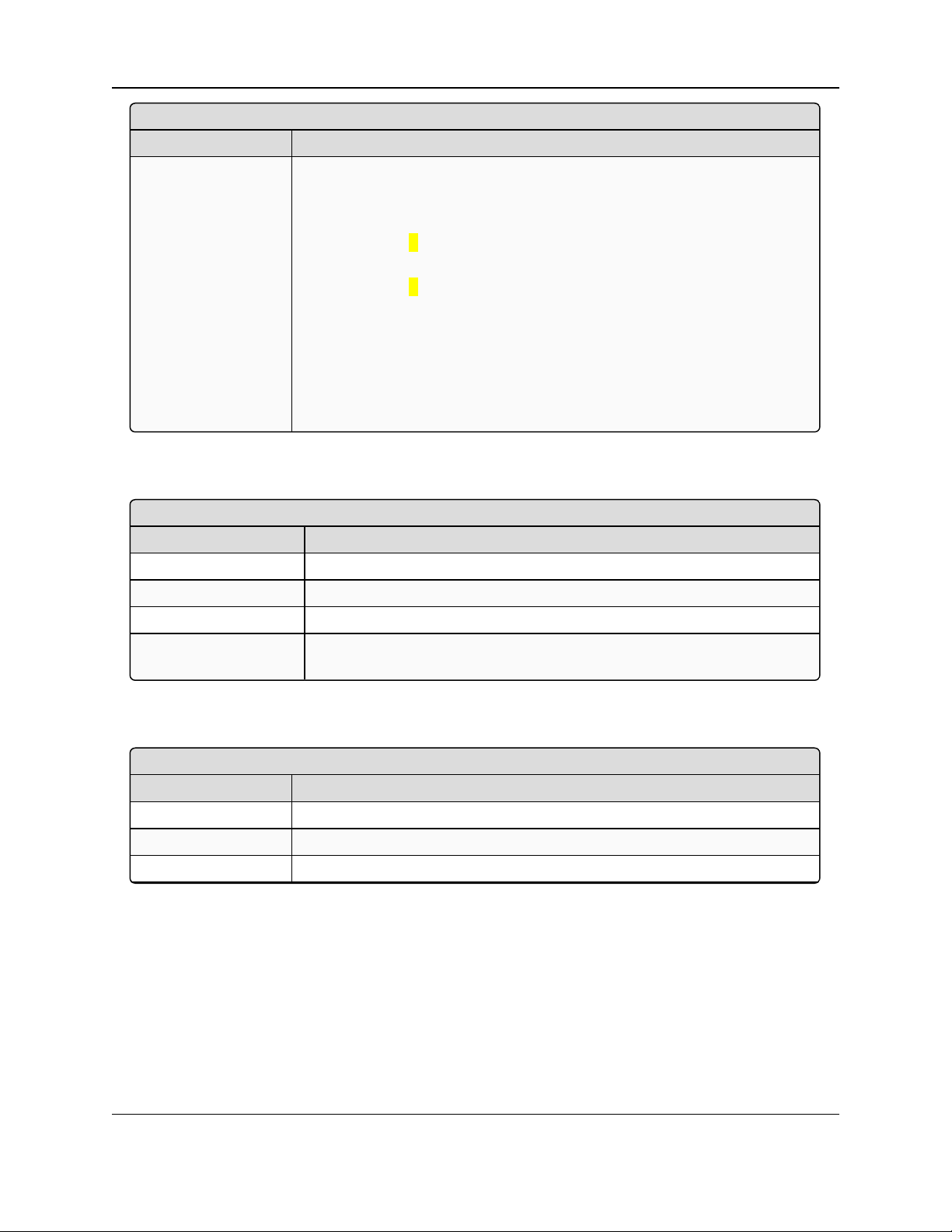
5.3.3. Flow Control
Flow Control
Setting Description
Default Setting: (0) None
Options: l (0) None: No flow control CTS is active and de-asserts when buffering is
98% full.
l Can pass XON/XOFF data but does not use it in any way.
l (1) RTS: Uses RTS/CTS (Request to Send/Clear to Send) for flow
control.
l (2) DTR: Uses DTR/DSR (Data TerminalReady/Data Set Ready) for
flow control.
l (3) DOT: Half Duplex
Note: (3) DOT: Half Duplex is NOT visible in the menu but is
accepted when 3 is entered.
l (3) DOTcauses the Carrier Detect (CD)line to indicate when data is
transmitted on the serial port from the radio.
l When the radio is NOT sending data to the serial port, CD is de-
asserted.
l When the radio is sending data to the serial port, CD is asserted and
the CD line no longer has any radio link state functionality.
Note:
Terminal Menu: (1) Set Baud Rate > (F) FlowControl
Description: l Specifies the hardware flow control for the data port on the radio.
l Flow control is the process of managing the speed at which data is
transmitted so as not to overwhelm the device receiving the transmission.
FREEWAVE Recommends: Use Flow Control if using a Baud
Rate higher than 38,400.
MM2-M13 Serial Radios: User & Reference Manual
5.3.4. Modbus RTU
Important!: When using the radio in Modbus RTU mode, the Master Packet Repeat (1) (on page 66)
MUST match in every radio regardless of whether the network is in Point-to-Point or MultiPoint
mode.
The Modbus RTU mode must be selected when radios are configured in RS422 or RS485 mode.
LUM0021AA Rev Mar-2018 Page 31 of 119
This document is the property of FreeWave Technologies, Inc. and contains proprietary information owned by
FreeWave. This document cannot be reproduced in whole or in part by any means without written permission from
FreeWave Technologies, Inc.
Page 32

5. Basic Radio Programming and Setup
Modbus RTU
Setting Description
Default Setting: (0) Disabled
Options: 0 to 9
Terminal Menu: (1) Set Baud Rate > (B) Modbus RTU
Description: A setting other than 0 in this parameter causes the radio to wait for an amount of
time gathering data before sending out the RF link.
l 0 (Disabled) - The radio sends data out through its RF link as soon as the data
is received into the serial port. This is the default setting.
l 1 - The radio waits for a number of slots equal to two times the Master Packet
Repeat setting before sending the received data out the RF link.
l With a setting of 1, the radio waits for a number of slots equal to two times
the Master Packet Repeat setting before sending the received data out the
RF link.
Example: If the Master Packet Repeat parameter is set to 3, the
radio waits for 6 slots, gathering data up the whole time.
At the end of the 6 slots, the radio sends all received data in one
“burst.” This is the appropriate setting for most Modbus RTU devices.
l 2 or higher - The radio waits for a number of slots calculated using this
formula:
(Modbus RTU setting + Master Packet Repeat setting + 1) x 2
Example: In a radio where the Modbus RTU setting is 2 and the
Master Packet Repeat setting is 3, the radio waits for(2+3+1)x2,
or 12 slots.
RS422 / RS485 (Serial Interface)
Setting Description
Default Setting: (0) RS232
5.3.5. RS422 / RS485 (Serial Interface)
Page 32 of 119 LUM0021AA Rev Mar-2018
This document is the property of FreeWave Technologies, Inc. and contains proprietary information owned by
FreeWave. This document cannot be reproduced in whole or in part by any means without written permission from
FreeWave Technologies, Inc.
Page 33

MM2-M13 Serial Radios: User & Reference Manual
RS422 / RS485 (Serial Interface)
Setting Description
Options: l (0) RS232: Also used for TTL.
l (1) RS422:
l Modbus RTU (on page 31) must be Enabled.
l (2) RS485:
l Modbus RTU (on page 31) must be Enabled.
l (3) DOT:
l Causes the CD line to indicate when data is transmitted on the serial
port from the radio.
l When the radio is sending data to the serial port, CD is asserted.
l When the radio is NOT sending data to the serial port, CD is de-
asserted.
l The CD line no longer has any radio link state functionality.
l Turn Off Delay (on page 34) works as described in all radios.
l Turn On Delay (on page 34) works as described on any Slave or
Slave/Repeater - it has no functionality on the Master radio.
Important!: If set to anything other than 0, the Setup Port parameter
on the Baud Rate tab MUST be set to Diagnostics Only.
Terminal Menu: (1) Set Baud Rate > (C) RS232 / RS485
Description: Use this option to set the protocol of the data port for connection to an
external device.
Important!: This setting must be 0 in TTL MM2-M13-T and MM2-
M13-LV-T board products.
Setup Port
Setting Description
Default Setting: (3) Both
5.3.6. Setup Port
Caution: Do NOT change this setting unless the correct programming cable is available for the
new setting.
LUM0021AA Rev Mar-2018 Page 33 of 119
This document is the property of FreeWave Technologies, Inc. and contains proprietary information owned by
FreeWave. This document cannot be reproduced in whole or in part by any means without written permission from
FreeWave Technologies, Inc.
Page 34

5. Basic Radio Programming and Setup
Setup Port
Setting Description
Options: l (1) Main Only: Programming and reading the radio's setup information is
done through the Data port.
l (2) Diagnostics Only: Programming and reading the radio's setup
information is done through the Diagnostic port.
l If the Serial interface is set to anything other than RS232, then the
Setup Port must be set to Diagnostics Only.
l (3) Both: Programming and reading the radio's setup information is done
through either the Data port or the Diagnostic port.
Terminal Menu: (1) Set Baud Rate > (D) Setup Port
Description: Determines which port on the radio, Main or Diagnostics, is used to access
the parameter settings in the Setup main menu in the terminal interface.
Press <Shift+U> to activate the Setup mode to the Diagnostics port or by
temporarily grounding pin 2.
l The OEM modules use a 2-row, 2 mm female connector.
l The main Data port:
l is the RS232 port.
l consists of the Data Rx, Data Tx, Gnd, and handshaking pins.
l The Diagnostics port consists of the Diag Rx, Diag Tx, and Gnd pins.
Use Break to Access Setup
Setting Description
Default Setting: (0) Disabled
Options: l (0) - Disabled: The break command is disabled.
l (1) - Enabled: The Setup menu is sent at 19,200 bps.
l (2) - Enabled: The Setup menu is sent at the radio's current Baud Rate.
l This setting is ONLY available through the terminal interface.
Terminal Menu: (1) Set Baud Rate > (G) Use break to access setup
5.3.7. Turn Off Delay
Note: The MM2-M13 Serial Radio does NOT use this parameter.
5.3.8. Turn On Delay
Note: The MM2-M13 Serial Radio does NOT use this parameter.
5.3.9. Use Break to Access Setup
Page 34 of 119 LUM0021AA Rev Mar-2018
This document is the property of FreeWave Technologies, Inc. and contains proprietary information owned by
FreeWave. This document cannot be reproduced in whole or in part by any means without written permission from
FreeWave Technologies, Inc.
Page 35

MM2-M13 Serial Radios: User & Reference Manual
Use Break to Access Setup
Setting Description
Description: Enables a break command to put the radio into Setup mode over the data
port.
l To send a break character, the end device must hold the transmit data
line in the space voltage level for longer than 1 character time.
Example: If a character is defined as having 1 start bit, 8 data bits,
and 1 stop bit, the character time is 10 bits, thus the transmit data line
must be held in the space voltage level for a period of time longer than
10 bits.
5.4. Establishing Communication with Other Radios in the Network
For the radios in the network to communicate successfully, the radios need to communicate with
the other available devices. Use one of these options:
l Network ID: Used in MultiPoint Networks, the Network ID parameter is on the MultiPoint
Parameters menu.
l Each radio in a single network should be assigned the same Network ID.
l A Slave links with the first Master or Repeater that it hears that has a matching Network
ID.
l Because the Network ID does not use serial numbers, MultiPoint Masters and
Repeaters may be replaced without reprogramming all of the Slaves in the network.
l The Network ID function should be used in conjunction with the Subnet ID feature (if
necessary) to route data through the radio network.
l Without having the serial numbers in the Call Book, Slaves may establish
communications with different Masters that match the radio's Golden Settings (on page
36), though not at the same time.
l This is very useful in mobile MultiPoint applications.
Note: For information about setting the Network ID parameter in a MultiPoint Network, see
Using the Network ID in Multipoint Networks (on page 56).
l Call Book: The Call Book is required in Point-to-Point networks.
l The Call Book stores serial numbers of other radios in the network that are allowed to talk
to a radio.
l Using the Call Book offers both security and flexibility in determining how FreeWave
LUM0021AA Rev Mar-2018 Page 35 of 119
This document is the property of FreeWave Technologies, Inc. and contains proprietary information owned by
FreeWave. This document cannot be reproduced in whole or in part by any means without written permission from
radios communicate with each other.
l For more information about defining the Call Book in a Point-to-Point network, see
Using Call Book in Point-to-Point Networks (on page 81).
l For more information about defining the Call Book in a Point-to-MultiPoint network,
see Using Call Book in Multipoint Networks (on page 57).
FreeWave Technologies, Inc.
Page 36

5. Basic Radio Programming and Setup
5.4.1. Golden Settings
A standard network requires that these parameters are set the same on all radios in the network FreeWave refers to these as the golden settings.
l Frequency Key in 1.3GHz Radios (on page 37)
l Max Packet Size (1) and Min Packet Size (2) (on page 43)
l Network ID (6) (on page 68)
l RF Data Rate (4) (on page 46)
Radios that contain the same settings in all these parameters can communicate with each other.
Important!: If Call Book is used instead of the Network ID, or a Point-to-Point network is running,
the appropriate serial numbers MUST be listed in the Call Book for each radio.
If working with parallel Repeaters, the Frequency Key setting may differ.
5.5. Setting RF Transmission Characteristics
The Transmission Characteristics parameters are used to change settings that determine how
data is sent between radios in the network. Many of these parameters must be maintained
throughout the network for proper functionality.
The parameters in the Transmission Characteristics menu are for advanced users with a good
understanding of the principles of RF transmission.
Note: Most parameters in the Edit Radio Transmission Characteristics menu can be left to their
default settings when completing basic setup.
l Several settings on a Slave or Repeater radio come from the Master and are set ONLY at
the Master.
l These settings MUST be set on every Slave / Repeater:
l Hop Freq Offset (2) (on page 40)
l Hop Table Size (1) (on page 40)
l Hop Table Version (0) (on page 41)
l Retry Time Out (8) (on page 45)
l RF Xmit Power (5) (on page 47)
l Slave Security (6) (on page 49)
Page 36 of 119 LUM0021AA Rev Mar-2018
This document is the property of FreeWave Technologies, Inc. and contains proprietary information owned by
FreeWave. This document cannot be reproduced in whole or in part by any means without written permission from
FreeWave Technologies, Inc.
Page 37

MM2-M13 Serial Radios: User & Reference Manual
Caution: These parameters MUST be set AND they must be the same for all radios in the
network.
l Frequency Key in 1.3GHz Radios (on page 37)
l Hop Freq Offset (2) (on page 40)
l Hop Table Size (1) (on page 40)
l Hop Table Version (0) (on page 41)
l Max Packet Size (1) and Min Packet Size (2) (on page 43)
l RF Data Rate (4) (on page 46)
5.5.1. Frequency Key in 1.3GHz Radios
Selecting 0 on the Radio Parameters menu allows the hopping patterns of the radio to be
changed.
l Fifteen choices are available for the FreqKey (0-9 and A-E) setting, representing 15
different pseudo-random hop patterns.
l FreqKey is used to minimize the interference with other FreeWave radios operating in the
area.
Example: If ten pairs of FreeWave radios are operating on different networks in close
proximity to each other, using a different FreqKey value reduces the chance that radios will
hop to the same frequency at the same time.
If two networks were to hop to the same frequency, the next hop would be to a different
frequency for both networks.
l Adjust the Max and Min Packet Size options to gain additional network separation.
l The default value is 5.
Procedure
1. Type 0 Freq Key.
2. Type any value between 0 and E to select an existing pseudo-random hop pattern.
3. Type 1 Max Packet Size.
4. Type any value between 0 and 9.
5. Type 2 Min Packet Size.
6. Type any value between 0 and 9.
7. Type F for additional options.
The Hop Table Parameters appear.
Note: All radios in a network must have identical Hop Table settings to function properly.
LUM0021AA Rev Mar-2018 Page 37 of 119
This document is the property of FreeWave Technologies, Inc. and contains proprietary information owned by
FreeWave. This document cannot be reproduced in whole or in part by any means without written permission from
FreeWave Technologies, Inc.
Page 38

5. Basic Radio Programming and Setup
Frequency Zone (3)
Setting Description
Default Setting: 1
Figure 16: 0 > F > Hop Table Parameters
8. Define additional network differentiation by limiting the number and location of frequencies
the radios can hop on in the 1350 – 1390 MHz band.
9. Press <Esc> to return to the Main Menu.
5.5.2. Frequency Zone (3)
Note: Frequency Zone entries begin with 1 (LSB) and continue through 16 (MSB).
Page 38 of 119 LUM0021AA Rev Mar-2018
This document is the property of FreeWave Technologies, Inc. and contains proprietary information owned by
FreeWave. This document cannot be reproduced in whole or in part by any means without written permission from
FreeWave Technologies, Inc.
Page 39

Frequency Zone (3)
Setting Description
Options:
Binary Zone Number
(LSB First MSB Last)
Beginning
Freq. (MHz)
Ending
Freq. (MHz)
Number
of Channels
1 1350.1440 1352.6784 12
2 1352.9088 1355.2128 11
3 1355.4432 1357.7472 11
4 1357.9776 1360.2816 11
5 1360.5120 1362.8160 11
6 1363.0464 1365.3504 11
7 1365.5808 1367.8848 11
8 1368.1152 1370.6496 12
9 1370.8800 1373.1840 11
10 1374.4144 1375.7184 11
11 1375.9488 1378.2528 11
12 1378.4832 1380.7872 11
13 1381.0176 1383.3216 11
14 1383.5520 1385.8560 11
15 1386.0864 1388.3904 11
16 1388.6208 1389.7728 6
Terminal Menu: (3) Edit Radio Transmission Characteristics > (0) FreqKey > (F) More > (3)
Frequency Zone
Description: Frequency zoning is used to divide the available band (1.350 GHz – 1.390
GHz) into 16 smaller bands, each consisting of 6, 11, or 12 frequency
channels, depending on the frequency zone.
l The 16 zones are stored in a Microsoft® Word file, made up of 16 bits
numbered 1-16.
l These bits, when shown in LSB to MSB, directly represent the zones that
the radio operates on from lowest frequency to highest.
l A 1 value in the bit sequence instructs the radio to operate within the
represented band.
l A 0 value instructs the radio to bypass the represented band.
Important!: This feature should only be used with the Hop Table
Version (0) (on page 41).
MM2-M13 Serial Radios: User & Reference Manual
FreeWave. This document cannot be reproduced in whole or in part by any means without written permission from
LUM0021AA Rev Mar-2018 Page 39 of 119
This document is the property of FreeWave Technologies, Inc. and contains proprietary information owned by
FreeWave Technologies, Inc.
Page 40

5. Basic Radio Programming and Setup
Hop Freq Offset (2)
Setting Description
Default Setting: 0
Options: l 0 - no offset
l 1 - 115.2 kHz offset
l 2 - 230.4 kHz offset
Terminal Menu: (3) Edit Radio Transmission Characteristics > (0) FreqKey > (F) More > (2)
Hop Table Offset
Description: The Hop Freq Offset (2) parameter is used to shift the center frequency of all
channels by either 115.2 kHz or 230.4 kHz.
Regardless of the FreqKey used, all radios MUST be set in either Point-toPoint or Point-to-MultiPoint networks:
l Hop Table Version (0) (on page 41)
l Hop Table Size (1) (on page 40)
l Hop Freq Offset (2)
Hop Table Size (1)
Setting Description
Default Setting: 112
Options: 75-112
Terminal Menu: (3) Edit Radio Transmission Characteristics > (0) FreqKey > (F) More > (1)
Hop Table Size
Description: The Hop Table Size defines how many separate channels are used by a
given network.
5.5.3. High Noise (A)
Note: High Noise is shown in the menu but is NOT supported in the MM2-M13 Serial Radio.
5.5.4. Hop Freq Offset (2)
The Hop Freq Offset setting is used to select a frequency offset of 115.2 kHz or 230.4 kHz,
which is higher than the standard frequency selection. Using this option helps to separate radio
networks that are located in the same geographic area.
Example: If two networks are operating in the same area with one set to Hop Freq Offset = 0 and
the other set to Hop Freq Offset = 1, the frequencies used in the hopping patterns are separated by
115.2 kHz, even if the hopping patterns are the same.
5.5.5. Hop Table Size (1)
FreeWave. This document cannot be reproduced in whole or in part by any means without written permission from
Page 40 of 119 LUM0021AA Rev Mar-2018
This document is the property of FreeWave Technologies, Inc. and contains proprietary information owned by
FreeWave Technologies, Inc.
Page 41

5.5.6. Hop Table Version (0)
Hop Table Version (0)
Setting Description
Default Setting: 0 (zero)
Options:
Selection Band
0 1350 – 1390 MHz
1 1350 – 1360 MHz
2 1360 – 1370 MHz
3 1370 – 1380 MHz
4 1380 – 1390 MHz
5 1350 – 1370 MHz
6 1370 – 1390 MHz
Terminal Menu: (3) Edit Radio Transmission Characteristics > (0) FreqKey > (F) More > (0)
Hop Table Version
Description: The Hop Table Version option is used to specify the portion of the band the
radio can operate in.
Lowpower Mode (9)
Setting Description
Default Setting: (0) Disable
Options: 0-31
Terminal Menu: (3) Edit Radio Transmission Characteristics > (9) Low Power Mode
Description: The Lowpower Mode option allows a Multipoint Slave to consume less
power by dimming the radio's LEDs.
l When Lowpower Mode is set to 2 through 31, the radio sleeps between
slots.
Example: A setting of 2 and the radio sleeps 1 out of 2 slots.
A setting of 3 and the radio sleeps 2 out of 3 slots.
MM2-M13 Serial Radios: User & Reference Manual
5.5.7. Lowpower Mode (9)
This table shows:
l The changes at different Lowpower Mode settings.
l The actual current draw depends on many factors.
l Only a qualitative indication of supply current savings.
l A low number reduces latency and a high number reduces current consumption.
LUM0021AA Rev Mar-2018 Page 41 of 119
This document is the property of FreeWave Technologies, Inc. and contains proprietary information owned by
FreeWave. This document cannot be reproduced in whole or in part by any means without written permission from
FreeWave Technologies, Inc.
Page 42

5. Basic Radio Programming and Setup
Current Draw Setting Description
More 0 Lowpower, disabled.
1 l LEDs are dimmed.
l Radio remains awake, listening to the Master’s transmissions on
every slot.
l The radio’s data port is shut down if the RTS line is de-asserted
(low).
l In this case, the radio needs to be awakened before it can send data
to the Master.
2 LEDs dimmed, radio sleeps every other slot.
3 LEDs dimmed, radio sleeps 2 of 3 slots.
Less 4-31 LEDs dimmed, radio sleeps the number of slots corresponding to the
setting.
Example: Using a setting of 31, the radio sleeps 30 of 31 slots.
Important Notes
l Lowpower Mode is used only in Multipoint Slave using serial protocol.
l Power savings occur only when the Slave is linked.
l No power savings occur when the Slave is transmitting data.
l Lowpower Mode is of little value when a Slave has a constant, high throughput.
l For Lowpower Mode to operate properly, MCU Speed must be set to 0 and RF Data
Rate must be set to 3.
l Additional power savings are realized when Number Repeaters is set to 1.
l To communicate to a TTL port of a radio that is in Lowpower Mode, the RTS line must be
held high to wake it up.
l The radio wakes up within approximately 20 milliseconds of when RTS goes high.
l If the RTS line on the Slave is held high, the radio remains in normal operation regardless of
the Lowpower Mode setting.
l Once RTS is dropped, the radio reverts to the Lowpower Mode.
l If the radio has the DTRConnect option set to 1 or 2 and if the Lowpower Mode enabled
(set to 1-31), the RTS line on the radio must be asserted for the DTRConnect feature to
operate properly.
l Disable or terminate the Diagnostic pins to a cable for the Sleep current in Lowpower
Mode to match the specifications.
l To disable the Diagnostics pins, verify the:
l (1) Baud Rate / (D) Setup Port is set to 1, Main Only.
l (5) Multipoint Parameters / (B) Diagnostics is set to 0, Off.
Page 42 of 119 LUM0021AA Rev Mar-2018
This document is the property of FreeWave Technologies, Inc. and contains proprietary information owned by
FreeWave. This document cannot be reproduced in whole or in part by any means without written permission from
FreeWave Technologies, Inc.
Page 43

MM2-M13 Serial Radios: User & Reference Manual
Minimum Packet Size Definition
Min Setting
Min Packet Size
RF Data Rate = 2
Min Packet Size
RF Data Rate = 3
0 15 8
1 21 12
2 26 16
3 31 20
4 37 24
5 42 28
6 47 32
7 53 36
8 58 40
9 63 44
5.5.8. Max Packet Size (1) and Min Packet Size (2)
The Max and Min Packet Size settings and the RF Data Rate determine the number of bytes in
the packets. Throughput can be enhanced when packet sizes are optimized.
l In Point-to-Point mode, the Max and Min Packet Size settings do NOT have material
impact on throughput unless 115.2 kbps is desired.
l However, this has an impact on latency.
Example: If small amounts of data are sent and large packet sizes are selected, a certain
amount of time “wasted” between each packet would be seen.
These three tables provide the information to determine optimum setting values.
l The default settings for Max Packet Size, Min Packet Size, and RF Data Rate are 8, 9,
and 2, respectively.
Minimum Packet Size Definition Table
The Minimum Packet Size Definition table defines the minimum packet size in bytes by way of
charting the Min Packet Size setting versus the RF Data Rate setting. Using the default settings,
the actual minimum packet size, in bytes, is 44.
Maximum Packet Size Definition with RF Date Rate of 2
The Maximum Packet Size Definition with RF Date Rate of 2 table defines the maximum
packet size in bytes by way of charting the Min Packet Size setting versus the Max Packet Size
setting where the RF Data Rate is set to 2.
LUM0021AA Rev Mar-2018 Page 43 of 119
This document is the property of FreeWave Technologies, Inc. and contains proprietary information owned by
FreeWave. This document cannot be reproduced in whole or in part by any means without written permission from
FreeWave Technologies, Inc.
Page 44

5. Basic Radio Programming and Setup
Maximum Packet Size Definition with RF Date Rate of 2
Min Setting Max Setting
0 1 2 3 4 5 6 7 8 9
0 15 37 58 79 101 122 143 165 186 207
1 21 42 63 85 106 127 149 170 191 213
2 26 47 69 90 111 133 154 175 197 218
3 31 53 74 95 117 138 159 181 202 223
4 37 58 79 101 122 143 165 186 207 229
5 42 63 85 106 127 149 170 191 213 234
6 47 69 90 111 133 154 175 197 218 239
7 53 74 95 117 138 159 181 202 223 245
8 58 79 101 122 143 165 186 207 229 250
9 63 85 106 127 149 170 191 213 234 255
Maximum Packet Size Definition with RF Date Rate of 3
Min Setting Max Setting
0 1 2 3 4 5 6 7 8 9
0 8 24 40 56 72 88 104 120 136 152
1 12 28 44 60 76 92 108 124 140 156
2 16 32 48 64 80 96 112 128 144 160
3 20 36 52 68 84 100 116 132 148 164
4 24 40 56 72 88 104 120 136 152 168
5 28 44 60 76 92 108 124 140 156 172
6 32 48 64 80 96 112 128 144 160 176
7 36 52 68 84 100 116 132 148 164 180
8 40 56 72 88 104 120 136 152 168 184
9 44 60 76 92 108 124 140 156 172 188
l Referencing the default settings, the Master transmits a minimum of 63 bytes and can
transmit up to 234 bytes on every hop.
l If fewer than 234 bytes are transmitted, the balance less 63, is allocated to the Slave's
transmission, plus the quantity in the Min Packet Size setting.
Note: Using the default settings, the actual maximum packet size, in bytes, is 234.
Maximum Packet Size Definition with RF Date Rate of 3
The Maximum Packet Size Definition with RF Date Rate of 3 table defines the maximum
packet size in bytes by way of charting the Min Packet Size setting versus the Max Packet Size
setting where the RF Data Rate is set to 3.
Page 44 of 119 LUM0021AA Rev Mar-2018
This document is the property of FreeWave Technologies, Inc. and contains proprietary information owned by
FreeWave. This document cannot be reproduced in whole or in part by any means without written permission from
FreeWave Technologies, Inc.
Page 45

5.5.9. MCU Speed (B)
MCU Speed (B)
Setting Description
Default Setting: 1
Options: 0-1
Terminal Menu: (3) Edit Radio Transmission Characteristics > (M) MCU Speed
Description: MCU Speed controls the speed of the Micro Controller Unit in the radio.
l The default setting is 0 for low speed.
l Reduces current consumption.
l A setting of 1 is for high speed.
l Required for UDP operation.
l Required for 230 KBaud data port rate.
l A setting of 3 is for very high speed.
l Required for AES Encryption.
Retry Time Out (8)
Setting Description
Default Setting: 255
Options: 8-255
Terminal Menu: (3) Edit Radio Transmission Characteristics > (8) Retry Time Out
5.5.10. Remote LED (C)
MM2-M13 Serial Radios: User & Reference Manual
Note: Remote LED is shown in the menu but is NOT supported in the MM2-M13 Serial Radio.
5.5.11. Retry Time Out (8)
LUM0021AA Rev Mar-2018 Page 45 of 119
This document is the property of FreeWave Technologies, Inc. and contains proprietary information owned by
FreeWave. This document cannot be reproduced in whole or in part by any means without written permission from
FreeWave Technologies, Inc.
Page 46

5. Basic Radio Programming and Setup
Retry Time Out (8)
Setting Description
Description: The Retry Time Out parameter in a Slave or Repeater sets the delay the unit
waits before dropping the connection to a Master or Repeater in Multipoint
mode.
l The factory default is set at the maximum of 255.
l The maximum setting means that if 1 packet in 255 is sent
successfully from the Master to the Slave or Repeater, the link is
maintained.
l The minimum setting is 8, which allows a Slave or Repeater to drop a
connection if less than 1 in 8 consecutive packets is successfully
received from the Master.
l The function in the Master is effectively the same.
l With a setting of 255, the Master allows a Slave or Repeater to stay
connected as long as 1 packet in 255 is successfully received at the
Master.
l The Retry Time Out parameter is useful when a Multipoint network has a
roving Master or Slave(s).
l As the link gets weaker, a lower setting allows a poor link to break in
search of a stronger one.
l Setting Retry Time Out to 20 is recommended in areas where several
FreeWave networks exist.
l This setting allows Slaves and Repeaters to drop the connection if the
link becomes too weak, while at the same time prevents errant
disconnects due to interference from neighboring networks.
Note: While intended primarily for Multipoint networks, the Retry
Time Out parameter can be changed in Point-to-Point networks.
However, do NOT set the value in Point-to-Point mode to less than
151.
RF Data Rate (4)
Setting Description
Default Setting: 2
Options: l 2 - 153.6 kbps
l 3 - 115.2 kbps
Terminal Menu: (3) Edit Radio Transmission Characteristics > (4) RF Data Rate
5.5.12. RF Data Rate (4)
Page 46 of 119 LUM0021AA Rev Mar-2018
This document is the property of FreeWave Technologies, Inc. and contains proprietary information owned by
FreeWave. This document cannot be reproduced in whole or in part by any means without written permission from
FreeWave Technologies, Inc.
Page 47
RF Data Rate (4)
Setting Description
Description: FreeWave radios have two settings, 2 and 3, for the RF Data Rate.
l The RF Data Rate should not be confused with the serial port Baud
Rate.
l Use setting 2 (RF Speed of 153.6 kbps) when the radios are close
together and data throughput needs to be optimized.
l Use setting 3 (RF Speed of 115.2 kbps) when the radios are farther away
and a solid data link is preferred over data throughput.
l In Multipoint networks, the RF Data Rate MUST be identical on all radios.
l Any radio with an RF Data Rate different from the Master will not
establish a link.
l In Point-to-Point networks, the Master’s settings take precedence over
the Slave’s settings.
5.5.13. RF Xmit Power (5)
RF Xmit Power (5)
Setting Description
Default Setting: 10
Options: 0 (zero) to 10
Terminal Menu: (3) Edit Radio Transmission Characteristics > (5) RF Xmit Power
Description: The RF Xmint Power option sets the RF output transmit power of the
radio.
RTS to CTS (7)
Setting Description
Default Setting: 0 (zero)
Options: 0-2
Terminal Menu: (3) Edit Radio Transmission Characteristics > (7) RTS to CTS
MM2-M13 Serial Radios: User & Reference Manual
5.5.14. RTS to CTS (7)
LUM0021AA Rev Mar-2018 Page 47 of 119
This document is the property of FreeWave Technologies, Inc. and contains proprietary information owned by
FreeWave. This document cannot be reproduced in whole or in part by any means without written permission from
FreeWave Technologies, Inc.
Page 48

5. Basic Radio Programming and Setup
RTS to CTS (7)
Setting Description
Description:
Note: The RTS to CTS menu option is under the Radio Parameters
menu.
The RTS to CTS parameter is used to allow the RTS line on the Master radio
to control the CTS line of the Slave.
l This pass-through control is enabled in both Point-to-Point and Point-to-
MultiPoint networks.
l In Multipoint networks, the Master RTS line controls all Slave's CTS
lines.
l When enabled, the CTS line ceases to function as Flow Control.
FREEWAVE Recommends: Do NOT enable this feature
when operating at Baud Rates above 38.4kB.
l The default setting of 0 disables the RTS to CTS function.
l A setting of 1 enables RTS-CTS control.
l With an RTS to CTS setting of 1, the Master senses the RTS line prior
to all scheduled packet transmissions.
l If the state has changed, the Master transmits a message to the Slave
with the new status.
l This transmission occurs regardless of data being sent.
l If data is ready to be sent, the RTS status message is sent in addition
to the data.
l In Point-to-Point mode, the Master continues sending the new status
message until it receives an acknowledgment from the Slave.
l In Multipoint mode, the Master repeats the message the number of times
equal to the Master Packet Repeat value in the Multipoint Parameters
menu.
l Master transmit times are completely asynchronous to the occurrence of
any change of the RTS line.
l The latency time from RTS to CTS is variable.
l The Max and Min Packet Size parameters in the Radio Parameter
menu determine this duration.
l Setting both parameters to their maximum value of 9 produces a
maximum latency time of approximately 21 ms, if there are no
Repeaters in the network.
l At the minimum settings for Max and Min Packet Size (0), the time is
approximately 5.9ms.
l RTS-CTS setting 2 is described in detail in the Application Note #5437
DTR to CTS Line Alarm Feature (available at
http://support.freewave.com/).
Page 48 of 119 LUM0021AA Rev Mar-2018
This document is the property of FreeWave Technologies, Inc. and contains proprietary information owned by
FreeWave. This document cannot be reproduced in whole or in part by any means without written permission from
FreeWave Technologies, Inc.
Page 49

MM2-M13 Serial Radios: User & Reference Manual
Single Freq (4)
Setting Description
Default Setting: 131
Options: 76 to 248
Note: See Single Frequency Setting (on page 114)
Terminal Menu: (3) Edit Radio Transmission Characteristics > (0) FreqKey > (F) More > (4)
Single Freq
Description: The Single Frequency parameter is used to set the single frequency the
radio operates on.
Slave Security (6)
Setting Description
Default Setting: 1
Options: l 0 - Enabled
l 1 - Disabled
l Latency can increase significantly if packets are lost between the Master and Slave.
l In Point-to-Multipoint mode, no absolute guarantee is made that the state change is
communicated to all Slaves.
l In Multipoint networks with Repeaters present, the latency is cumulative for each serial
Repeater.
Example: If the latency between the Master and the first Repeater is 15 ms AND two serial
Repeaters are present, the total latency is 45 ms.
(M-R1 (15 ms) + R1-R2 (15 ms) + R2-S (15 ms) = 45 ms).
Important!: The RTS to CTS feature does NOT function in Point-to-Point networks that
contain a Repeater.
If this feature is needed in such a network, change the mode to Point-to-Multipoint.
l If DTRConnect is enabled and set to 2, the RTS to CTS feature will not work.
l If the DTRConnect is enabled and set to 1, the RTS to CTS mode takes precedence over
the functionality of the CTS line on the Slave relating to the DTRConnect feature.
5.5.15. Single Freq (4)
The Single Freq option is used to set which specific frequency the MM2-M13 Serial Radio uses
when set to Single Frequency Mode.
Note: When set to Single Frequency Mode, the (0) FreqKey shows a value of 15.
5.5.16. Slave Security (6)
LUM0021AA Rev Mar-2018 Page 49 of 119
This document is the property of FreeWave Technologies, Inc. and contains proprietary information owned by
FreeWave. This document cannot be reproduced in whole or in part by any means without written permission from
FreeWave Technologies, Inc.
Page 50

5. Basic Radio Programming and Setup
Slave Security (6)
Setting Description
Setup Terminal Menu: (3) Edit Radio Transmission Characteristics > (6) Slave Security
Description: Slave Security is used to allow Slave radios to accept transmissions from a
Master not included in the Call Book.
l The default setting is 0, Slave Security Enabled.
l This allows only a Master listed in the Slave's Call Book to link to that
Slave.
l Using a setting of 1 disables Slave Security.
l This allows any Master to call the Slave.
l Slave Security has no effect in Point-to-Multipoint networks where the
Network ID is not set to 255.
l Slave Security MUST be set to 1 when the unit is operating in Mode 6
Slave/Master Switchable or a Point-to-Point network where the
Slave needs to accept calls from more than 10 different Masters.
l When Slave Security is set to 1, the radio accepts calls from any other
FreeWave radio.
l Additional network security measures can be taken to prevent
unauthorized access (e.g., changing default settings for FreqKey, Hop
Table, or Frequency Zones).
Xmit Rate (3)
Setting Description
Default Setting: 1
Options: 0-1
Terminal Menu: (3) Edit Radio Transmission Characteristics > (3) Xmit Rate
Description: Two settings for the Transmit Rate parameter are available: 1 and 0.
l The setting for normal operation of the radio is a Transmit Rate 1.
l When set to Transmit Rate 0, the radios transmit back and forth
continuously.
l Transmit Rate 0 is useful to gauge signal strength in Point-to-Point
mode.
l In Point-to-Point operation, Transmit Rate 0 should be used only as a
diagnostic tool and not for normal operation.
l The strength of the signal may be gauged by the Clear to Send LED.
l A solid red CTS LED ( ) indicates a strong signal, while a blinking CTS
LED ( ) indicates a weaker signal.
5.5.17. Xmit Rate (3)
FreeWave. This document cannot be reproduced in whole or in part by any means without written permission from
Page 50 of 119 LUM0021AA Rev Mar-2018
This document is the property of FreeWave Technologies, Inc. and contains proprietary information owned by
FreeWave Technologies, Inc.
Page 51

MM2-M13 Serial Radios: User & Reference Manual
6. Configuring
Point-to-MultiPoint Networks
When installing Multipoint networks, it is important to do some up front planning around the
devices to implement and the route the data is going to take back to the Master. A Multipoint
network can contain these devices:
l Only one Master. All communications are from and to the Master.
l An unlimited number of Slave radios (remote sites).
l An unlimited number of Repeaters between any Slave and the Master.
l Serial Repeaters can be Slave radios and Repeaters at the same time.
This section provides details specifically to a Multipoint network:
l Point-to-MultiPoint network characteristics.
l Using the Network ID or Call Book to establish which radios in the network can
communicate with each other.
l Using Subnet IDs to route traffic through the network, back to the Master.
l Settings and recommendations for additional parameters that apply to a Multipoint network.
l Conserving power in devices within the network.
l Running network diagnostics.
LUM0021AA Rev Mar-2018 Page 51 of 119
This document is the property of FreeWave Technologies, Inc. and contains proprietary information owned by
FreeWave. This document cannot be reproduced in whole or in part by any means without written permission from
FreeWave Technologies, Inc.
Page 52

6. Configuring Point-to-MultiPoint Networks
6.1. Point-to-MultiPoint Network Characteristics
A Point-to-MultiPoint network has these unique characteristics.
l Golden Settings (on page 52)
l Master-to-Slave Communications (on page 52)
l Slave-to-Master Communications (on page 52)
6.1.1. Golden Settings
A Point-to-MultiPoint network requires that the Golden Settings (on page 36) are set the same on
all radios in the network.
Note: If several independent Multipoint networks are located in close proximity, the planning
becomes more critical. In such cases, it becomes very important to include as much frequency and
time diversity as possible through use of different Min and Max Packet Size.
In some instances, the use of the MultiMaster Sync option may be required.
l For more information, about the MultiMaster Sync setting, see Application Note #5412,
Synchronizing Collocated Masters (available at http://support.freewave.com/) or
contact FreeWave Technical Support.
l In almost all Multipoint networks, the Frequency Key is the same for all radios.
l In other networks, where parallel Repeaters are used, the Frequency Key value needs to
change.
6.1.2. Master-to-Slave Communications
Master-to-Slave communications within a Multipoint network have these characteristics:
l Data packets sent from the Master include a 32-bit CRC.
l The Master repeats its data broadcast between 0 to 9 times, depending on the setting in the
Master Packet Repeat setting. For more information, see Master Packet Repeat (1) (on
page 66).
l A Slave or Repeater does not send acknowledgments to the Master when it receives data.
l When any Slave in the network receives the data packet from the Master with the 32-bit
CRC, that Slave ignores any additional repeats of the data, and passes the data to its
data port.
l Repeaters in the network send data to Slave radios and other Repeaters.
6.1.3. Slave-to-Master Communications
Slave-to-Master communications within a Multipoint network have these characteristics:
l Data packets sent from the Slave to the Master include a 32-bit CRC.
l When the Master successfully receives data, it sends an acknowledgment to the Slave and
passes the data to its data port.
Page 52 of 119 LUM0021AA Rev Mar-2018
This document is the property of FreeWave Technologies, Inc. and contains proprietary information owned by
FreeWave. This document cannot be reproduced in whole or in part by any means without written permission from
FreeWave Technologies, Inc.
Page 53

MM2-M13 Serial Radios: User & Reference Manual
6.2. Quick Start on a Point-to-Multipoint Network
This procedure sets up two radios in Point-to-Multipoint mode. This mode allows for a Master to
communicate with several Repeaters and Slaves simultaneously.
1. Connect the radio to the serial port of a computer either through a serial cable or via the
diagnostics cable.
2. Connect the radio to a power source.
Important!: Power supply ranges and recommendations vary depending on model.
Verify the specifications for the model prior to connecting power.
3. Open a terminal emulator session and use these settings when connecting the radio:
a. Connect to COMx (where 'x' is the number of the COM port being connected).
b. Set these parameters to:
i. Data Rate = 19200
ii. Data Bits = 8
iii. Parity = None
iv. Stop Bits = 1
v. Flow Control = None
4. Press the Setup button on the radio.
If using the diagnostics cable, type <Shift+U>.
l The three LEDs on the radio should all turn green ( ), indicating Setup mode.
l The Main Menu appears in the window.
5. Type 0 and press <Enter> to access the Operation Mode menu.
6. Type 2 and press <Enter> to set the radio as a Point-to-MultiPoint Master OR
Type 3 to set the radio as a Point-to-MultiPoint Slave.
7. Press <Esc> to return to the Main Menu.
Note: A MultiPoint network can have only one Master, unless running in Multi-Master Synch
mode.
8. On the Main Menu, type 1 and press <Enter>.
9. Change the Baud Rate, Data, Parity, and Modbus RTU to match the device that the
radio is to be attached to.
10. Press <Esc> to return to the Main Menu.
11. On the Main Menu, type 3 and press <Enter>.
12. Set these parameters so they are the same on all radios in the network:
l FreqKey
l Max Packet Size
l Min Packet Size
l RF Data Rate
LUM0021AA Rev Mar-2018 Page 53 of 119
This document is the property of FreeWave Technologies, Inc. and contains proprietary information owned by
FreeWave. This document cannot be reproduced in whole or in part by any means without written permission from
FreeWave Technologies, Inc.
Page 54

6. Configuring Point-to-MultiPoint Networks
The Frequency Key option is located in the F submenu after 0 is typed to access the
Frequency Key menu in Main Menu 3.
Changing these values may help to eliminate interference from other FreeWave
networks.
13. Press <Esc> to return to the Main Menu.
14. On the Main Menu, type 5 and press <Enter>.
15. In the Network ID field, enter the value to any value between 1 and 4095.
FREEWAVE Recommends: Set the Network ID to the last three or four digits of the Master
radio's serial number if it is below 4095.
This value MUST be the same in all radios in the network
Note: A setting of 255 disables the Network ID feature and enables the Call Book feature.
16. Press <Esc> to exit the Setup menu and resume normal radio operation.
Page 54 of 119 LUM0021AA Rev Mar-2018
This document is the property of FreeWave Technologies, Inc. and contains proprietary information owned by
FreeWave. This document cannot be reproduced in whole or in part by any means without written permission from
FreeWave Technologies, Inc.
Page 55

6.3. Point-to-MultiPoint Operation LEDs
Master Slave Repeater
Condition
Carrier
Detect
(CD)
Transmit
(Tx)
Clear to
Send
(CTS)
Carrier
Detect
(CD)
Transmit
(Tx)
Clear to
Send
(CTS)
Carrier
Detect
(CD)
Transmit
(Tx)
Clear to
Send
(CTS)
Powered, not linked Solid red
bright
Solid red
dim
Off
Solid red
bright
Off
Blinking
red
Solid red
bright
Off
Blinking
red
Repeater and Slave linked
to Master.
No data.
Solid red
bright
Solid red
dim
Off
Solid
green
Off
Solid red
bright
Solid
green
Solid red
dim
Solid red
bright
Repeater and Slave linked
to Master.
Master sending data to
Slave.
Solid red
bright
Solid red
dim
Off
Solid
green
Off
Solid red
bright
Solid
green
Solid red
dim
Solid red
bright
Repeater and Slave linked
to Master.
Slave sending data to
Master.
Solid green RCV data
or Solid red
bright
Solid red
dim
Intermittent
flash red
Solid
green
Intermittent
flash red
Solid red
bright
Solid
green
Solid red
bright
Solid red
bright
Master with diagnostics
program running.
Solid red
bright
Solid red
dim
Intermittent
flash red
Solid
green
Intermittent
flash red
Solid red
bright
Solid
green
Solid red
bright
Solid red
bright
MM2-M13 Serial Radios
Note: * In an idle condition, the CTS LED is solid red with a solid link, as the link weakens the CTS LED on the Repeater and Slave begins
to blink .
LUM0021AA Rev Mar-2018 Page 55 of 119
This document is the property of FreeWave Technologies, Inc. and contains proprietary information owned by FreeWave. This document cannot be reproduced
in whole or in part by any means without written permission from FreeWave Technologies, Inc.
Page 56

6. Configuring Point-to-MultiPoint Networks
6.4. Overlapping Multipoint Networks
Overlapping MultiPoint networks may be set up effectively when several key parameters are set
correctly. Overlapping MultiPoint networks are defined as networks using different Master radios,
which share or overlap in a specific geographic area. It may also include collocated radios
configured into different networks.
For more information, see Application Note #5412, Synchronizing Collocated Masters (Multi-
Master Sync Mode) (available at http://support.freewave.com/).
Collocated MultiPoint networks require these parameters be unique for each network:
l Network ID (unless using the Call Book)
l Frequency Key (with Repeater Frequency)
l Max Packet Size
l Min Packet Size
Note: For more information about the installation of Point-to-MultiPoint networks, contact FreeWave
Technical Support.
See Contact FreeWave Technical Support (on page 7)
6.5. Establishing Communication with Other Radios in a Multipoint Network
For the radios in the network to communicate successfully, the radio needs to know what other
devices are available for them to communicate with. Use the Network ID or the Call Book.
FREEWAVE Recommends: While the Call Book is an option in Point-to-MultiPoint networks,
FreeWave strongly recommends using the Network ID feature in most applications.
If a large MultiPoint network is implemented using the Call Book and a radio needs to be added to or
replaced in the network, each radio in the network must be physically reprogrammed and the new
serial number entered in the radio's Call Book.
This can be a time consuming process and can cause a delay in getting the network back up and
running.
Because the Network ID does not use serial numbers, MultiPoint Master radios and Repeaters may
be added or replaced without reprogramming each Slave radio in the network.
6.5.1. Using the Network ID in Multipoint Networks
The Network ID parameter is located on the MultiPoint Parameters tab. Assign each radio in a
single network the same Network ID. Slave radios link with the first Master or Repeater it hears
that has a matching Network ID.
When setting the Network ID:
l The value can be any value between 1 and 4095, except 255.
l 255 enables the Call Book.
l To help ensure the ID is unique to the network, avoid using numbers that coincide with
nearby landmarks or highways.
Page 56 of 119 LUM0021AA Rev Mar-2018
This document is the property of FreeWave Technologies, Inc. and contains proprietary information owned by
FreeWave. This document cannot be reproduced in whole or in part by any means without written permission from
FreeWave Technologies, Inc.
Page 57

MM2-M13 Serial Radios: User & Reference Manual
Entry Number Repeater 1 Repeater 2
(0) 000-0000
(1) 000-0000
Example: Use the last four digits of the Master serial number if it is below 4095.
This is ensured to be unique and does not overlap with other nearby FreeWave networks.
l Use the Network ID function in conjunction with the Subnet ID feature (if necessary) to
route data through the radio network.
6.5.2. Using Call Book in Multipoint Networks
Important!: Although NOT recommended, the Call Book is an option in MultiPoint networks. If the
Network ID feature is used in a MultiPoint network, no entries are needed in the Call Book of any of
the radios.
FREEWAVE Recommends: While the Call Book is an option in Point-to-MultiPoint networks,
FreeWave strongly recommends using the Network ID feature in most applications.
If a large MultiPoint network is implemented using the Call Book and a radio needs to be added to or
replaced in the network, each radio in the network must be physically reprogrammed and the new
serial number entered in the radio's Call Book.
This can be a time consuming process and can cause a delay in getting the network back up and
running.
Because the Network ID does not use serial numbers, MultiPoint Master radios and Repeaters may
be added or replaced without reprogramming each Slave radio in the network.
Important!: Using the Call Book in a MultiPoint network can cause delay in resuming
communications if a Master is damaged.
Note: For information about setting the Call Book, see Using Call Book in Point-to-Point Networks
(on page 81).
In a MultiPoint network, the Slave radios and Repeaters are not listed in the Master radio's Call
Book. Slave radios must have the Master and any Repeater it is going to use in its Call Book.
These examples show the Call Book of a MultiPoint network comprised of a Master, Repeater,
and Slave in which the Slave can communicate either through the Repeater or directly to the
Master.
MultiPoint Master Call Book (Unit Serial Number 900-0001)
Note: No serial number entries are necessary in the Master’s Call Book.
LUM0021AA Rev Mar-2018 Page 57 of 119
This document is the property of FreeWave Technologies, Inc. and contains proprietary information owned by
FreeWave. This document cannot be reproduced in whole or in part by any means without written permission from
FreeWave Technologies, Inc.
Page 58

6. Configuring Point-to-MultiPoint Networks
Entry Number Repeater 1 Repeater 2
(0) 900-0001
(1) 000-0000
Entry Number Repeater 1 Repeater 2
(0) 900-0001
(1) 900-0002
(2) 000-0000
MultiPoint Repeater Call Book (Unit Serial Number 900-0002)
MultiPoint Slave Call Book (Unit Serial Number 900-0003)
At times, the Slave radios need to be forced to go through a specific MultiPoint Repeater.
In this scenario, the Slave radio's Call Book should contain only the serial number for that
Repeater as the entry on line 0.
6.5.3. Programming Point-to-Multipoint Extended Call Book
In a MultiPoint network, Slave radios can be programmed to roam between Master radios and
Repeaters using the MultiPoint Extended Call Book function. Slave radios with Call Book, as
configured in this procedure, communicate with any radio whose serial number appears in any of
the three columns.
Procedure
1. Set the Network ID to 255.
2. In the Call Book, enter 999-9999 as the last entry in the first and second columns.
3. In the Call Book, set Entry to Call to All.
Figure 17: HyperTerminal PTMP Extended Call Book
Page 58 of 119 LUM0021AA Rev Mar-2018
This document is the property of FreeWave Technologies, Inc. and contains proprietary information owned by
FreeWave. This document cannot be reproduced in whole or in part by any means without written permission from
FreeWave Technologies, Inc.
Page 59

MM2-M13 Serial Radios: User & Reference Manual
6.6. Routing Communications through the Network
When using the Network ID, a Repeater or Slave links to the first Repeater or Master it hears
with the same ID.
l Use Subnet IDs to determine the path a Repeater or Slave uses to communicate back to
the Master.
l Subnet IDs are particularly helpful to force:
l Two Repeaters in the same network to operate in series rather than in parallel.
l Slave radios to communicate to a specific Repeater for load balancing purposes.
Note: Forcing the communications path optimizes the performance of the network by ensuring the
Repeater or Slave links to a Repeater or Master with robust RF communications. Subnet IDs can
help to minimize latency.
6.6.1. Assigning Subnet ID Values
Subnet IDs consist of two parts, both available on the MultiPoint Parameters tab:
l Rx - This setting identifies which radio a Repeater or Slave listens to.
l In the terminal interface, this is the Rcv Subnet ID.
l Tx - This setting identifies the ID this device transmits on and which devices listen to it.
l The Tx Subnet ID parameter is relevant for MultiPoint Master radios and Repeaters
only.
l In the terminal interface, this is the Xmt Subnet ID.
l The default (disable) setting for both Rx and Tx is F, F.
l This is a visual way to indicate that the device is the final in the line of communication and
does not use a subnet ID.
l A MultiPoint Slave with a Subnet ID of F, F does not roam from one Repeater or network
to the next.
l It only links to a Master or Repeater that has either a Transmit Subnet setting of 0 or an
F, F Subnet ID.
l Setting both Rx and Tx Subnet ID to 0 allows a mobile Slave to roam from subnet to
subnet, and possibly from network to network, provided the Network ID, Max and Min
Packet Size, and RF Data Rates are the same between networks.
The examples in this section show the subnet definitions from the Master radio through the
network to the Slave radios. When the subnet path is defined, the Slave radios can follow the
route back to the Master.
LUM0021AA Rev Mar-2018 Page 59 of 119
This document is the property of FreeWave Technologies, Inc. and contains proprietary information owned by
FreeWave. This document cannot be reproduced in whole or in part by any means without written permission from
FreeWave Technologies, Inc.
Page 60

6. Configuring Point-to-MultiPoint Networks
Subnet and Specific Path Communication
Radio Rx Tx Additional Information
Master 0 0 l The default settings (F, F) actually use 0, 0.
l The Rx Subnet on the Master has no effect on the
network.
Repeater 1 0 1 Rx Subnet = 0 forces communication through the Master.
Repeater 2 1 2 l Rx Subnet = 1 forces communication through
Repeater 1.
l Repeater 1 transmits on SubnetID 2.
Slave 2 F l Rx Subnet = 2 forces communication through
Repeater 2.
l The Slave is the end of the network, so its Tx Subnet is
F.
Example 1: Subnet and Specific Path Communication
This example shows a network in which subnet IDs are used to force communications along a
specific path.
Figure 18: Subnet and Specific Path Communication
Page 60 of 119 LUM0021AA Rev Mar-2018
This document is the property of FreeWave Technologies, Inc. and contains proprietary information owned by
FreeWave. This document cannot be reproduced in whole or in part by any means without written permission from
FreeWave Technologies, Inc.
Page 61

MM2-M13 Serial Radios: User & Reference Manual
Subnet and Communication Required through Repeaters
Radio Rx Tx Additional Information
Master 0 0 l The default settings (F, F) actually use 0, 0.
l The Rx Subnet on the Master has no effect on the
network.
Slave 1 0 F l Rx Subnet = 0 forces communication through the
Master.
l The Slave does not transmit to any device except the
Master, so its Tx Subnet is F.
Repeater 1 0 1 l Rx Subnet = 0 forces communication through the
Master.
l Repeater 1 transmits on SubnetID 1.
Slave 2 0 F Rx Subnet = 0 forces communication through the Master.
Slave/Repeater 2 1 2 l Rx Subnet = 1 forces communication through Repeater
1.
l It transmits on Tx Subnet 2 to Slave 4 and 5.
Slave 3 1 F l Rx Subnet = 1 forces communication through Repeater
1.
l The Slave does not transmit to any device except
Repeater 1, so its Tx Subnet is F.
Slave 4 2 F Rx Subnet = 2 forces communication through
Slave/Repeater 2.
Slave 5 2 F Rx Subnet = 2 forces communication through
Slave/Repeater 2.
Example 2: Subnet and Communication Required through Repeaters
This example shows:
l Repeater 2 must communicate through Repeater 1.
l The Slave connected to Repeater 1 must route through Repeater 1.
l The other two Slave radios must route through Slave/Repeater 2.
Figure 19: Subnet and Communication Required through Repeaters
This document is the property of FreeWave Technologies, Inc. and contains proprietary information owned by
FreeWave. This document cannot be reproduced in whole or in part by any means without written permission from
LUM0021AA Rev Mar-2018 Page 61 of 119
FreeWave Technologies, Inc.
Page 62

6. Configuring Point-to-MultiPoint Networks
Subnet and Optional Slave Communication
Radio Rx Tx Additional Information
Master 0 or F 0 or F l The default settings (F, F) actually use 0, 0.
l The Rx Subnet on the Master has no effect on the network.
Repeater 1 0 1 Rx Subnet = 0 forces communication through the Master.
Repeater 2 1 2 l Rx Subnet = 1 forces communication through Repeater 1.
l Repeater 1 transmits on SubnetID 1.
Slave 1 0 0 or F Rx Subnet = 0 forces communication through the Master.
Slave 2 1 0 or F Rx Subnet = 1 forces communication through Repeater 1.
Slave 3 2 0 or F Rx Subnet = 2 forces communication through Repeater 2.
Slave 4 0 0 The 0, 0 setting allows the Slave to link with the first Master or
Repeater it hears with the same Network ID.
Example 3: Subnet and Optional Slave Communication
This example shows:
l Repeater 1 must talk directly to the Master.
l Repeater 2 must talk directly to Repeater 1.
l Slave 1, 2, and 3 are forced along the direction of the solid lines.
l Slave 4 may link to the first Master or Repeater it hears in the network.
Figure 20: Subnet and Optional Slave Communication
Page 62 of 119 LUM0021AA Rev Mar-2018
This document is the property of FreeWave Technologies, Inc. and contains proprietary information owned by
FreeWave. This document cannot be reproduced in whole or in part by any means without written permission from
FreeWave Technologies, Inc.
Page 63

MM2-M13 Serial Radios: User & Reference Manual
1 PPS Enable/Delay (9)
Setting Description
Default Setting: 255
Options: 0 (zero) to 255
Note: Pulse-per-second 255 is Off.
Terminal Menu: (5) Edit Multipoint Parameters > (9) 1 PPS Enable/Delay
Description: The 1 PPS Enable/Delay (9) setting allows a 1PPS signal to propagate from
the Master to all Slaves in a MultiPoint network.
When this parameter is enabled a properly generated pulse applied on the
DTR line of the Master provides a 1 PPS pulse on the CD line of any Slave in
the network.
6.7. Setting Other Multipoint Parameters
The other MultiPoint Parameters options are used to modify several different parameters in the
radio that determine the characteristics of a MultiPoint network.
These settings are available in the MultiPoint Parameters menu in the terminal interface.
Note: See the Parameter Preference (on page 8) for a description of the parameter table's content.
6.7.1. 1 PPS Enable/Delay (9)
Important!: When 1 PPS is enabled, the Master radio must have a 1 PPS pulse on its DTR pin,
otherwise the RF network does not function.
Setup 1PPS Enable/Delay
1. On the Master radio, set the 1 PPS Enable/Delay parameter to 0.
Note: The Master must have a 1 PPS pulse on the DTR pin, otherwise the RF network will
not function.
2. Enable the 1 PPS Enable/Delay parameter on the Slave radios.
Slave radios are calibrated at the factory.
Calibrate a Slave Radio in 1PPS Enable/Delay Mode
1. On the Master radio, trigger an oscilloscope on the 1 PPS pulse on the DTR line.
2. Monitor the CD line of the Slave radio.
3. If the timing on the Slave radio differs from the Master it may be adjusted via the value in the
Slave radio's 1 PPS Enable/Delay parameter.
LUM0021AA Rev Mar-2018 Page 63 of 119
This document is the property of FreeWave Technologies, Inc. and contains proprietary information owned by
FreeWave. This document cannot be reproduced in whole or in part by any means without written permission from
FreeWave Technologies, Inc.
Page 64

6. Configuring Point-to-MultiPoint Networks
Diagnostics (B)
Setting Description
Default Setting: (0) Diagnostics
Options: 0 to 129
Terminal Menu: (5) Edit Multipoint Parameters > (B) Diagnostics
Description: Diagnostics, provides diagnostic data at the Master radio in parallel with
application data.
l The diagnostic program MUST be run from the Master radio.
l Diagnostics requires:
l Diagnostics set from 0 - 129 in the Master.
l A second computer or serial connection to run the diagnostics
software.
l A diagnostics cable. (Available from FreeWave Technologies, Inc..)
l Diagnostics software.
Note: For more information on Diagnostics, Contact FreeWave
Technical Support (on page 7)
DTR Connect (4)
Setting Description
Default Setting: 0 (zero)
Options: l (0) Off - When set to off in the Slave radio, the radio transmits when the
data is received.
l (1) DTR Sensing - Forms a Point-to-Point link with the Master radio when
the DTR line is high to send data.
l (2) Burst Mode - The radio transmits data in bursts.
Notes
l The difference in time between each incremental integer value is 542.534 nanoseconds
(ns).
l Changing the parameter to higher values decreases the Slave radio time delay and
changing the parameter to lower values increases the time delay.
l When properly calibrated, the CD line Slave radio outputs a pulse that goes high for about 2
ms in sync with the 1 PPS pulse on the Master radio.
l The output on the Slave radio occurs within 20 microseconds of the input to the Master.
6.7.2. Diagnostics (B)
6.7.3. DTR Connect (4)
Page 64 of 119 LUM0021AA Rev Mar-2018
This document is the property of FreeWave Technologies, Inc. and contains proprietary information owned by
FreeWave. This document cannot be reproduced in whole or in part by any means without written permission from
FreeWave Technologies, Inc.
Page 65

MM2-M13 Serial Radios: User & Reference Manual
DTR Connect (4)
Setting Description
Terminal Menu: (5) Edit Multipoint Parameters > (4) DTR Connect
Description: Determines how the radio sends its data.
Note: This mode is valuable when a network has many low data rate
devices and to increase overall network capacity.
l If DTR Connect is set to 1 and the RTS to CTS function is enabled on
the radio, then RTS to CTS takes precedence over DTR Connect.
l If DTR Connect is set to 2 and RTS to CTS is enabled, then RTS to
CTS is ignored.
The radio has two separate transmit and receive user data buffers of 2kb
each.
Caution: In case of a buffer overflow, the radio outputs
unpredictable data.
Local Access (E)
Setting Description
Default Setting: 0 (zero)
Options: 0-1
l 0 = Normal mode
l 1 = Enables Local Access
Terminal Menu: (5) Edit Multipoint Parameters > (E) Local Access
Description: Local Access is used to access an MM2-M13 Serial Radio Multipoint Slave
with a local Master.
Important!: This Master is NOT the network master.
Note: For more information, see Application Note #5457, Local Mode
(available at http://support.freewave.com/).
Registration is required to use this login.
6.7.4. Local Access (E)
LUM0021AA Rev Mar-2018 Page 65 of 119
This document is the property of FreeWave Technologies, Inc. and contains proprietary information owned by
FreeWave. This document cannot be reproduced in whole or in part by any means without written permission from
FreeWave Technologies, Inc.
Page 66

6. Configuring Point-to-MultiPoint Networks
Master Packet Repeat (1)
Setting Description
Default Setting: 0 (zero)
Options: 0 to 9
Terminal Menu: (5) Edit Multipoint Parameters > (1) Master Packet Repeat
Description: In a Point-to-MultiPoint network, Slave radios do not acknowledge
transmissions from the Master.
l If Slave radios did acknowledge all data transmissions, in a large
network, the Master would soon become overwhelmed with
acknowledgments from the Slaves.
l Without acknowledgments, 100% confidence every Slave radio has
received every packet cannot be met.
l To address this issue, change the Master Packet Repeat parameter,
assigning a value between 0 (the packet is transmitted once) to 9 (the
packet is transmitted 10 times).
For networks with solid RF links, this parameter should be set to a low value
(e.g., 1 or 2).
l If a network has some weak or marginal links it should be set with higher
values.
l If a Slave radio receives a good packet from a Master more than once it
discards the repeated packets.
l Similarly, after a MultiPoint Repeater receives a good packet from the
Master, it discards any further repeated packets.
l In turn, the Repeater sends the packet out to the next Repeater or Slaves
the number of times corresponding to its own Master Packet Repeat
setting.
Increasing the Master Packet Repeat setting increases the probability of a
packet getting through, but also increases latency in the network because
each packet from the Master or Repeater is being sent multiple times.
Note: Therefore, it is important to find the optimal mix between
network robustness, throughput, and latency.
In general, a setting of 2 to 3 works well for most well designed
networks.
The Master Packet Repeat parameter may be set to 0 if the user software is
capable of, or requires acknowledgment.
In this case, if the Master sends a packet that the Slave radio does not
receive, the user software controls the retries as needed.
6.7.5. Master Packet Repeat (1)
Page 66 of 119 LUM0021AA Rev Mar-2018
This document is the property of FreeWave Technologies, Inc. and contains proprietary information owned by
FreeWave. This document cannot be reproduced in whole or in part by any means without written permission from
FreeWave Technologies, Inc.
Page 67

MM2-M13 Serial Radios: User & Reference Manual
Max Slave Retry (2)
Setting Description
Default Setting: 9
Options: 0-9
Terminal Menu: (5) Edit Multipoint Parameters > (2) Master Slave Retry
Description: Max Slave Retry, defines how many times (0 to 9) the Slave attempts to
retransmit a packet to the Master before beginning to use a back-off
algorithm, which is defined by the Retry Odds (3) (on page 70) setting.
Slave retries stop when an acknowledgment is received from the Master.
MultiMasterSync (8)
Setting Description
Default Setting: 0 (zero)
Options: 0-1
l 0 = Master Sync
l 1 = Otherwise
Terminal Menu: (5) Edit Multipoint Parameters > (8) MultiMasterSync
6.7.6. Master Packet Repeat in Multipoint Networks with Repeaters
The Master Packet Repeat parameter must be set in MultiPoint Repeaters because a Repeater
appears as a Master to a Slave radio.
Therefore, the Repeater sends the packet out the number of times corresponding to its own
Master Packet Repeat parameter setting. If this parameter is set improperly the reliability of the
overall network may be diminished.
Example: If a Master's Master Packet Repeat parameter setting is 3, the link between the Master
and Repeater should be robust.
If the Repeater's Master Packet Repeat parameter setting is 0, this could cause marginal links
between the Repeater and the Slaves.
The Slaves communicating through this Repeater only receive the initial packet from the Master with
no repeats.
Therefore, if the packet is not received on the first try, the Slave radio does not respond as expected.
Note: The Master Packet Repeat parameter setting in any MultiPoint Repeater must be less than
or equal to the Master's setting.
6.7.7. Max Slave Retry (2)
6.7.8. MultiMasterSync (8)
LUM0021AA Rev Mar-2018 Page 67 of 119
This document is the property of FreeWave Technologies, Inc. and contains proprietary information owned by
FreeWave. This document cannot be reproduced in whole or in part by any means without written permission from
FreeWave Technologies, Inc.
Page 68

6. Configuring Point-to-MultiPoint Networks
MultiMasterSync (8)
Setting Description
Description: MultiMaster Synch, is reserved for applications, in both Point-to-Point and
Multipoint modes, with concentrations of master units where it is necessary
to reduce interference between the masters.
Note: See Application Note #5412 Synch Colloc Master in Sync
Mode for more information (available at
http://support.freewave.com/).
Registration is required to use this login.
Network ID (6)
Setting Description
Default Setting: 0255
Options: 0-4095 (excluding 255)
Terminal Menu: (5) Edit Multipoint Parameters > (6) Network ID
Description: Network ID is used to establish Multipoint networks without using the Call
Book.
Set the value between 0 and 4095 (excluding 255) to enable Network ID.
Important!: The default setting of 0255 enables the Call Book.
l Since Network ID does NOT use serial numbers, Multipoint Masters and
Repeaters can be replaced without reprogramming all of the Slaves in the
network.
l A Slave links with the first Master or Repeater that it hears that has a
matching Network ID.
l Use the Network ID function in conjunction with the Subnet ID (C) (on
page 72) setting.
l Without having the serial numbers in the Call Book, a Slave establishes
communications with different Masters, though not at the same time.
This is very useful in mobile Multipoint applications.
6.7.9. Network ID (6)
6.7.10. Number Repeaters (0)
Important!: In a Multipoint network it is critical to transmission timing to configure this parameter
correctly.
Page 68 of 119 LUM0021AA Rev Mar-2018
This document is the property of FreeWave Technologies, Inc. and contains proprietary information owned by
FreeWave. This document cannot be reproduced in whole or in part by any means without written permission from
FreeWave Technologies, Inc.
Page 69

Number Repeaters (0)
Setting Description
Default Setting: 1
Options: 0 (zero), 1-9
Terminal Menu: (5) Edit Multipoint Parameters > (0) Number Repeaters
Description: l Set the Number Repeaters value to 0 if there are NO Repeaters in the
network.
l Set the Number Repeaters value from 1-9 if there are Repeaters in the
network.
Note: In a Point-to-MultiPoint network, the Number Repeaters
parameter is set in the Master.
6.7.11. Radio ID (D)
Radio ID (D)
Setting Description
Default Setting: Not Set
Options: 0 to 9999
Terminal Menu: (5) Edit Multipoint Parameters > (D) Radio ID
Description: Radio ID is used to designate a radio with an arbitrary, user selectable, four
digit number that identifies the radio in diagnostics mode.
Radio Name (G)
Setting Description
Default Setting: None
Options: A maximum of 20 alpha-characters
Terminal Menu: (5) Edit Multipoint Parameters > (G) Radio Name
Description: Radio Name is used to set a radio name in the radio settings.
l The radio name can have a maximum of 20 characters (letters, numbers,
or spaces).
l This value is recognized by some FreeWave diagnostics programs to help
identify the radio.
l This setting has no impact on radio communications.
MM2-M13 Serial Radios: User & Reference Manual
6.7.12. Radio Name (G)
LUM0021AA Rev Mar-2018 Page 69 of 119
This document is the property of FreeWave Technologies, Inc. and contains proprietary information owned by
FreeWave. This document cannot be reproduced in whole or in part by any means without written permission from
FreeWave Technologies, Inc.
Page 70

6. Configuring Point-to-MultiPoint Networks
Repeater Frequency (5)
Setting Description
Default Setting: 0 (zero)
Options: 0-1
Terminal Menu: (5) Edit Multipoint Parameters > (5) Repeater Frequency
Description: Repeater Frequency must be set to 1 in a Repeater when a FreqKey other
than the Master is needed.
l This condition occurs when parallel Repeaters in a network have
overlapping areas of responsibility.
l The default setting of 0 causes the Repeater to use the FreqKey set in
Menu 3.
l When Repeater Frequency is set to 0, the FreqKey setting must match
the Master or Repeater acting as the Master for the radio.
Retry Odds (3)
Setting Description
Default Setting: 0 (zero)
Options: 0 to 9
Terminal Menu: (5) Edit Multipoint Parameters > (3) Retry Odds
6.7.13. Repeater Frequency (5)
6.7.14. Retry Odds (3)
Page 70 of 119 LUM0021AA Rev Mar-2018
This document is the property of FreeWave Technologies, Inc. and contains proprietary information owned by
FreeWave. This document cannot be reproduced in whole or in part by any means without written permission from
FreeWave Technologies, Inc.
Page 71

MM2-M13 Serial Radios: User & Reference Manual
Retry Odds (3)
Setting Description
Description: While packets transmitted from the Master to the Slave radios in a MultiPoint
network are not acknowledged, packets transmitted from Slaves to the
Master are acknowledged.
It is possible that more than one Slave attempts to transmit to the Master at
the same time. Therefore, it is important that a protocol exists to resolve
contention for the Master between Slaves in the network.
This is addressed through the Max Slave Retry (2) (on page 67) and Retry
Odds (3) parameters.
l After the Slave has unsuccessfully attempted to transmit the packet the
number of times specified in the Max Slave Retry parameter, it attempts
to transmit to the Master on a random basis.
l The Retry Odds parameter determines the probability that the Slave
attempts to retransmit the packet to the Master; a low setting assigns low
odds to the Slave attempting to transmit.
l Conversely, a high setting assigns higher odds.
Example: Consider two different Slave radios in a MultiPoint
network, one with a strong RF link and the other with a weak RF
link to the Master.
If a Slave has a weak or poor link, set the Retry Odds parameter
to 0 as it may become a chatty Slave and lockup the network,
causing a loss of communication.
l When the Retry Odds parameter is set to 0, after the Slave has
exhausted the number of retries set in the Max Slave Retry parameter
and still not gained the Master’s attention, the Slave’s data buffer is
purged.
FREEWAVE Recommends: A Retry Odds parameter set to 0 is
recommended for most networks.
Slave/Repeater (A)
Setting Description
Default Setting: 0 (zero)
Options: 0 to 1
l 0 = Normal
l 1 = Enable Slave / Repeater
Terminal Menu: (5) Edit Multipoint Parameters > (A) Slave/Repeater
6.7.15. Slave/Repeater (A)
LUM0021AA Rev Mar-2018 Page 71 of 119
This document is the property of FreeWave Technologies, Inc. and contains proprietary information owned by
FreeWave. This document cannot be reproduced in whole or in part by any means without written permission from
FreeWave Technologies, Inc.
Page 72

6. Configuring Point-to-MultiPoint Networks
Slave/Repeater (A)
Setting Description
Description: The Slave/Repeater mode allows a radio in a MultiPoint network to switch
between Slave and Repeater functions.
l When in this mode, a radio repeats any packets sent across the network
as well as uses the data port.
l This allows one radio at one site.
Note: To operate a radio as a MultiPoint Slave/Repeater, use the
Multipoint Parameters menu and set the operation mode to
Multipoint Repeater (7) and Slave/Repeater (1).
6.7.16. Subnet ID (C)
Option C, Subnet ID, only works in Multipoint networks using the Network ID option. In a
Multipoint network, a Slave or Repeater connects with the first Repeater or Master it hears with
the same Network ID.
Subnet ID is particularly helpful to force two Repeaters in the same network to operate in series
rather than in parallel or to force Slaves to communicate to a specific Repeater for load balancing
purposes. Two components exist with regard to the Subnet ID:
l Rx Subnet ID - This setting identifies the radio a Repeater or Slave listens to.
l Xmit Subnet ID - This setting identifies the ID the device transmits on and the devices
listening to it. The Xmit Subnet ID parameter is relevant for Multipoint masters and
repeaters only.
The default (disable) setting for both Rx and Xmit is F.
Important!: Changing these settings on the Master is NOT recommended under normal
circumstances.
In some Multipoint Networks, the FreqKey is at the same setting for all radios. In other
networks, where parallel Repeaters are used, the FreqKey value needs to change.
l If both Rx Subnet ID and Xmit Subnet ID are set to 0 (zero), the Subnet ID shows
Roaming in the menu.
l This setting allows a mobile slave to roam from subnet to subnet and possibly from
network to network.
Figure 21 shows a network where Subnet IDs are used to force communications. In this
example:
l Repeater 1 must talk directly to the Master.
l Repeater 2 must talk directly to Repeater 1.
l Slaves 1, 2, and 3 are forced along the direction of the solid lines.
l Slave 4 links to the first Master or Repeater it hears.
Page 72 of 119 LUM0021AA Rev Mar-2018
This document is the property of FreeWave Technologies, Inc. and contains proprietary information owned by
FreeWave. This document cannot be reproduced in whole or in part by any means without written permission from
FreeWave Technologies, Inc.
Page 73

MM2-M13 Serial Radios: User & Reference Manual
Subnet ID Settings
Radio
Rx
Subnet ID
Xmit
Subnet ID
Other Information
Master F F The Master uses 0,0.
Master 0 0 l The Xmit Subnet ID value may be set in the Master.
l The default settings (F, F) actually use 0, 0.
l The Rx Subnet on the Master has no effect on the network.
Repeater1 0 1 Rx Subnet = 0 forces communication through the Master.
Repeater2 1 2 l Rx Subnet = 1 forces communication through Repeater 1.
l Repeater 1 transmits on SubnetID 1.
Slave1 0 0 or F Rx Subnet = 0 forces communication through the Master.
Slave2 1 0 or F Rx Subnet = 1 forces communication through Repeater 1.
Slave3 2 0 or F Rx Subnet = 2 forces communication through Repeater 2.
Slave4 0 0 The 0, 0 setting allows the Slave to link with the first Master or
Repeater it hears with the correct Network ID.
Figure 21: Subnet IDs Forcing Communication
6.8. Conserving Power
Power consumption can be essential, especially for remote sites that are difficult to access. Use
these options on the Transmission Characteristics tab to conserve power.
These settings are available in the Radio Transmission Characteristics menu in the terminal
interface.
l Low Power Mode - Available in MultiPoint Slaves using RS232.
LUM0021AA Rev Mar-2018 Page 73 of 119
This document is the property of FreeWave Technologies, Inc. and contains proprietary information owned by
FreeWave. This document cannot be reproduced in whole or in part by any means without written permission from
l Conserves power primarily by dimming the radio's LEDs.
Note: For more information, see Low Power Mode (on page 74).
l Remote LEDs - If the radio has the optional 20-in connector, use this option to connect
remote LEDs through the diagnostics port.
FreeWave Technologies, Inc.
Page 74

6. Configuring Point-to-MultiPoint Networks
Low Power Mode
Setting Description
Default Setting: 0
Options: Any number between 0 and 31.
Note: The higher the number, the greater the power consumption
decrease.
Warning! For firmware version 2.68 and later, a Low Power
Mode setting other than 0 for RS422 / RS485 causes the Slave
radio to disassociate from the network.
Terminal Menu: (3) Edit Radio TransmissionCharacteristics > (9) Low Power Mode
This feature may be used to save power in MultiPoint Repeaters where the other
options are not available.
Note: For more information, see Remote LED (C) (on page 45).
6.8.1. Low Power Mode
Note: This setting applies only to MultiPoint Slave radios using the RS232 protocol. Low Power
Mode does not work with MultiPoint Repeaters because they are constantly transmitting.
Page 74 of 119 LUM0021AA Rev Mar-2018
This document is the property of FreeWave Technologies, Inc. and contains proprietary information owned by
FreeWave. This document cannot be reproduced in whole or in part by any means without written permission from
FreeWave Technologies, Inc.
Page 75

MM2-M13 Serial Radios: User & Reference Manual
Low Power Mode
Setting Description
Description: The Low Power Mode setting allows a MultiPoint Slave radio to consume
less power, primarily by dimming the radio's LEDs.
l When set to 2 through 31, the radio sleeps between slots.
Example: A setting of 2 the radio sleeps 1 out of 2 slots; at a
setting of 3 the radio sleeps 2 out of 3 slots, and so on.
l When the radio is asleep, it hears nothing from the Master.
The is table shows the changes at different Low Power Mode settings.
Important!: The actual current draw depends on many factors. The
table provides only a qualitative indication of supply current savings.
Note: A low number reduces latency and a high number reduces
current consumption.
Setting Description
0 Low power, disabled.
1 l LEDs are dimmed.
l Radio remains awake, radio is listening to the
Master’s transmissions on every slot.
l Radio’s data port is shut down if the RTS line is de-
asserted (low).
l In this case, the radio needs to be awakened before it
is able to send data to the Master.
2 LEDs dimmed, radio sleeps every other slot.
3 LEDs dimmed, radio sleeps 2 of 3 slots.
4-31 LEDs dimmed, radio sleeps the number of slots
corresponding to the setting.
Example: Using a setting of 31 the radio sleeps
30 of 31 slots.
LUM0021AA Rev Mar-2018 Page 75 of 119
This document is the property of FreeWave Technologies, Inc. and contains proprietary information owned by
FreeWave. This document cannot be reproduced in whole or in part by any means without written permission from
FreeWave Technologies, Inc.
Page 76

6. Configuring Point-to-MultiPoint Networks
Low Power Mode
Setting Description
Notes
l Power savings occur only when the Slave radio is linked.
l No power savings occur when the Slave radio is transmitting data.
l Low Power Mode is of little value when a Slave has a constant, high
throughput.
l The MCU Speed parameter MUST be set to 0 and the RF Data Rate
parameter MUST be set to 3 for Low Power Mode to operate
properly.
l To communicate to an RS232 port of a radio that is in Low Power Mode,
the RTS line MUST be held high to wake it up.
l The radio wakes up within approximately 20 milliseconds of when RTS
goes high.
l If the Request to Send (RTS) line on the Slave radio is held high, the
radio remains in normal operation regardless of the Low Power Mode
setting.
l After RTS is dropped the radio reverts to the Low Power Mode.
l If the radio has the DTR Connect (4) (on page 64) parameter in the
MultiPoint Parameters tab set to 1 or 2 and if the Low Power Mode is
enabled (set to 1 to 31), the RTS line on the radio MUST be asserted
for the DTR Connect feature to operate properly.
l The diagnostic pins MUST be disabled or terminated to a cable for the
sleep current in Lower Power Mode to match the specifications.
l To disable the diagnostic pins, set these options:
l In the Baud Rate tab, the Setup Port (on page 33) parameter is set
to 1 (Main Only).
l In the MultiPoint Parameters tab, the Diagnostics (B) (on page 64)
parameter is set to 0 (Off).
l To realize full power savings in Low Power Mode, the serial port MUST
be deactivated between operation.
l To do that the RTS line MUST be asserted.
l However, because RS422 / RS485 operation uses the RTS line as
part of the data bus, it cannot be asserted to wake-up the radio.
FREEWAVE Recommends: All radios set to RS422 or RS485
use a Low Power Mode setting of0.
Page 76 of 119 LUM0021AA Rev Mar-2018
This document is the property of FreeWave Technologies, Inc. and contains proprietary information owned by
FreeWave. This document cannot be reproduced in whole or in part by any means without written permission from
FreeWave Technologies, Inc.
Page 77

MM2-M13 Serial Radios: User & Reference Manual
7. Configuring
Point-to-Point Networks
Point-to-Point networks are the most basic type of network and do not require much more than
the setup described in the basic programming and setup section.
This section provides:
l A brief quick start to setup a Point-to-Point network.
l An LED chart for LED function within a Point-to-Point network.
l Information about programming the Call Book.
7.1. Quick Start on a Point-to-Point Network
When purchased as a pair, the FreeWave radios are shipped from the factory pre-configured with
most of the settings to operate in Point-to-Point applications.
To establish a link between a pair of FreeWave radios just received from the factory, complete
these steps for each radio.
Procedure
1. Connect the radio to the serial port of a computer either through a serial cable or via the
diagnostics cable.
2. Connect the radio to a power source.
Note: Power supply ranges and recommendations vary depending on model.
Verify the specifications for the model you are using prior to connecting power.
3. Open a terminal emulator session.
4. Connect to COMx (where 'x' is the number of the COM port being connected).
5. Set these parameters to:
LUM0021AA Rev Mar-2018 Page 77 of 119
This document is the property of FreeWave Technologies, Inc. and contains proprietary information owned by
FreeWave. This document cannot be reproduced in whole or in part by any means without written permission from
FreeWave Technologies, Inc.
Page 78

7. Configuring Point-to-Point Networks
l Data Rate - 19,200
l Data Bits - 8
l Parity - none
l Stop bits - 1
l Flow Control - none
6. Press the Setup button on the radio.
If using the diagnostics cable, press <Shift+U>.
l When in Setup mode, all three LEDs on the radio display solid green .
l The Main Menu appears in the window.
7. Type 0 and press <Enter> to access the Operation Mode menu.
8. Type 0 and press <Enter> to set the radio as a Point-to-Point Master or
Type 1 and press <Enter> to set the radio as Point-to-Point Slave.
Note: For more information about modem modes, see Define the Radio's Role in the Network
and the Network Type (on page 27).
9. Press <Esc> to return to the Main Menu.
10. On the Main Menu, type 1 and press <Enter>.
11. Change the Baud Rate, Data, Parity, and Modbus RTU to match the device that the
radio is to be attached to.
12. Press <Esc> to return to the Main Menu.
13. On the Main Menu, type 2 and press <Enter> to update the Call Book.
14. Enter the Slave serial number in the Master’s Call Book.
15. Enter the Master’s Serial number in the Slave’s Call Book or
disable the Slave Security (6) (on page 49) parameter in the Slave.
Note: For more information about setting up the Call Book, see Using Call Book in Point-to-
Point Networks (on page 81).
16. On the Main Menu, type 3 and press <Enter>.
17. Set these parameters so they are identical on all radios in the network:
l Frequency Key
l Max Packet Size
l Min Packet Size
l RF Data Rate
Note: The Frequency Key option is located in the F submenu after you press <0> to access
the Frequency Key menu on Main menu <3>.
FREEWAVE Recommends: Changing these settings from the factory defaults may help to
eliminate interference from other FreeWave networks.
18. Press <Esc> to return to the Main Menu.
Page 78 of 119 LUM0021AA Rev Mar-2018
This document is the property of FreeWave Technologies, Inc. and contains proprietary information owned by
FreeWave. This document cannot be reproduced in whole or in part by any means without written permission from
FreeWave Technologies, Inc.
Page 79

MM2-M13 Serial Radios: User & Reference Manual
Shortly after both radios are plugged in, they should establish a link with each other and the
connection is complete.
19. Using the Point-to-Point Operation LEDs (on page 80), verify that the radios are operating
as expected.
20. Press <Esc> to exit the Setup menu and resume normal radio operation.
LUM0021AA Rev Mar-2018 Page 79 of 119
This document is the property of FreeWave Technologies, Inc. and contains proprietary information owned by
FreeWave. This document cannot be reproduced in whole or in part by any means without written permission from
FreeWave Technologies, Inc.
Page 80

7. Configuring Point-to-Point Networks
Master Slave Repeater
Condition
Carrier
Detect
(CD)
Transmit
(Tx)
Clear to
Send
(CTS)
Carrier
Detect
(CD)
Transmit
(Tx)
Clear to
Send
(CTS)
Carrier
Detect
(CD)
Transmit
(Tx)
Clear to
Send
(CTS)
Powered, no link Solid red
bright
Solid red
bright
Solid red
bright
Solid red
bright
Off
Blinking
red
Solid red
bright
Off
Blinking
red
Linked.
No Repeater
Sending sparse data
Solid
green
Intermittent flash red Intermittent
flash red
Solid
green
Intermittent
flash red
Intermittent
flash red
n/a n/a n/a
Master calling
Slave through Repeater
Solid red
bright
Solid red
dim
Solid red
bright
Solid red
bright
Off
Blinking
red
Solid red
bright
Off
Blinking
red
Master linked to
Repeater, not to Slave
Flashing or ange Solid red
dim
Solid red
bright
Solid red
bright
Off
Blinking
red
Solid
Red
bright
Solid red
dim
Solid red
bright
Repeater linked to Slave Solid
green
Intermittent
flash red
Intermittent
flash red
Solid
green
Intermittent
flash red
Intermittent
flash red
Solid
green
Intermittent
flash red
Intermittent
flash red
Mode 6
Waiting for AT D
command
Solid red
bright
Off
Blinking
red
Solid red
bright
Off
Blinking
red
n/a n/a n/a
Setup Mode Solid
green
Solid
green
Solid
green
Solid
green
Solid
green
Solid
green
Solid
green
Solid
green
Solid
green
7.2. Point-to-Point Operation LEDs
Page 80 of 119 LUM0021AA Rev Mar-2018
This document is the property of FreeWave Technologies, Inc. and contains proprietary information owned by FreeWave. This document cannot be reproduced
in whole or in part by any means without written permission from FreeWave Technologies, Inc.
Page 81

MM2-M13 Serial Radios: User & Reference Manual
7.3. Using Call Book in Point-to-Point Networks
Using the Call Book offers both security and flexibility in determining how FreeWave radios
communicate with each other.
Important!: The Call Book is required in Point-to-Point networks.
FREEWAVE Recommends: While the Call Book is an option in Point-to-MultiPoint networks,
FreeWave strongly recommends using the Network ID feature in most applications.
If a large MultiPoint network is implemented using the Call Book and a radio needs to be added to or
replaced in the network, each radio in the network must be physically reprogrammed and the new
serial number entered in the radio's Call Book.
This can be a time consuming process and can cause a delay in getting the network back up and
running.
Because the Network ID does not use serial numbers, MultiPoint Master radios and Repeaters may
be added or replaced without reprogramming each Slave radio in the network.
l The Call Book allows a maximum of 10 FreeWave radios.
l Designate 1 to 4 Repeaters to use with each radio.
l Designate which Slave the Master calls.
These settings are required for two FreeWave radios to communicate in Point-to-Point mode:
1. The Master radio serial number must be listed in the Slave radio's Call Book or Slave
Security is turned off in the Slave.
2. The Slave serial number must be listed in the Master Call Book.
3. The Master must be programmed to call the Slave (Entry to Call option).
a. Select the number in the Entry to Call field, select All to direct the Master to call all
Slave radios.
Note: To set the Entry to Call option in the terminal interface, press <C> at the Call Book
menu, followed by the menu number corresponding to that Slave.
To call any available Slave in the list, press <C> then press <A> to direct the Master to Call
All.
It is important that the Call Book slots (0-9) are filled sequentially starting with slot 0.
l When a Master is instructed to Call All, it calls all Slave radios listed until it reaches the first
serial number of 000-0000 (or a blank slot).
l If a serial number is entered after the all zero number or as a Repeater, the Master does not
recognize it as a valid number.
Note: When entering numbers into the Call Book, define only the Repeaters in the Master's Call
Book.
The Slave's Call Book only requires the Master serial number.
A Repeater need not have anything listed in its Call Book.
LUM0021AA Rev Mar-2018 Page 81 of 119
This document is the property of FreeWave Technologies, Inc. and contains proprietary information owned by
FreeWave. This document cannot be reproduced in whole or in part by any means without written permission from
FreeWave Technologies, Inc.
Page 82

7. Configuring Point-to-Point Networks
7.3.1. Programming Point-To-Point Extended Call Book to Use Three or Four Repeaters
In a Point-to-Point configuration, FreeWave radios can use a maximum of four Repeaters.
1. To use three or four Repeaters, program the Call Book with the Slave serial number,
followed by the first two Repeaters.
2. On the next line enter 999-9999 as the radio to call.
3. When prompted for the Repeaters enter the third and fourth Repeaters in the link.
The illustration shows a Point-to-Point link where a Slave is called through four Repeaters. In this
example:
l the Master is calling the Slave, 571-3872, through Repeater 1, 901-1234,
l then Repeater 2,910-0234,
l then Repeater 3, 571-3456, and finally
l Repeater 4, 571-4567.
l Entering the serial number 999-9999 in line 1 instructs the Master to continue calling
through the Repeaters programmed on that line.
Figure 22: Point-to-Point link where a Slave is called through four Repeaters
l To call a Slave radio through one or more Repeaters, that Slave must be called individually.
l With Call All selected, the Master will not connect with any Slave radios through
Repeaters.
l The Master calls every Slave in the list and connects with the first Slave that responds.
l When calling through a Repeater, the Master must first call that Repeater and establish a
communications link with it prior to making contact with the Slave.
Page 82 of 119 LUM0021AA Rev Mar-2018
This document is the property of FreeWave Technologies, Inc. and contains proprietary information owned by
FreeWave. This document cannot be reproduced in whole or in part by any means without written permission from
FreeWave Technologies, Inc.
Page 83

MM2-M13 Serial Radios: User & Reference Manual
8. Advanced Programming
The settings and scenarios covered in this section are considered advanced programming.
l Working with Parallel Repeaters (on page 84)
l Setting and Changing Radio Passwords (on page 86)
l Enable and Set Up AES Encryption (on page 87)
l Encryption Channel Key (on page 88)
l Encryption Key (on page 89)
l Encryption (Strength) (on page 91)
l Troubleshooting AES Setup (on page 91)
l Low Baud Rates (on page 92)
l Multi-Master Synch (on page 92)
l Time Divisible Multiple Access (TDMA) (on page 92)
LUM0021AA Rev Mar-2018 Page 83 of 119
This document is the property of FreeWave Technologies, Inc. and contains proprietary information owned by
FreeWave. This document cannot be reproduced in whole or in part by any means without written permission from
FreeWave Technologies, Inc.
Page 84

8. Advanced Programming
8.1. Working with Parallel Repeaters
When Repeaters are added to a network, plan accordingly to avoid creating a parallel Repeater
scenario. A parallel Repeater is defined as two or more Repeaters linked to the same point in the
network.
l Repeaters Data Transmitted on the Same Frequency Key (on page 84)
l Adding a Repeater to the Network (on page 85)
8.1.1. Repeaters Data Transmitted on the Same Frequency Key
In this diagram, the Slave radio in the middle has overlapping coverage from both the Repeaters
(parallel Repeaters). Data from the Repeaters is transmitted on the same Frequency Key in the
same time slot, which creates message collisions.
Figure 23: Slave Radio with Overlapping Coverage
To resolve this scenario, change these settings on one or more of the Repeaters in conflict:
Page 84 of 119 LUM0021AA Rev Mar-2018
This document is the property of FreeWave Technologies, Inc. and contains proprietary information owned by
FreeWave. This document cannot be reproduced in whole or in part by any means without written permission from
FreeWave Technologies, Inc.
Page 85

MM2-M13 Serial Radios: User & Reference Manual
Settings to Change on Repeaters in Conflict
Setting Description
Repeater
Frequency
l Set the Repeater Frequency parameter in the MultiPoint Parameters tab to
any number other than 0.
l If set to a number other than 0, the radio uses the frequency key set in the
Frequency Key parameter in the Transmission Characteristics tab, instead
of the frequency key assigned to the Master.
Frequency Key Set the Frequency Key parameter in the TransmissionCharacteristics tab to a
key other than that of the conflicting Repeater.
8.1.2. Adding a Repeater to the Network
Figure 24: Repeater Added to Network
If a Repeater needs to be added to the network, use these steps to ensure any parallel Repeater
issues are resolved before deploying the Repeater in the network.
1. In Tool Suite, run a network diagnostics file.
Gather the settings from all the Repeaters that are currently in the network.
2. Review the network diagnostics file.
FreeWave. This document cannot be reproduced in whole or in part by any means without written permission from
Pay special attention to these settings on each Repeater and the Master:
l Frequency Key
l Repeater Frequency
LUM0021AA Rev Mar-2018 Page 85 of 119
This document is the property of FreeWave Technologies, Inc. and contains proprietary information owned by
FreeWave Technologies, Inc.
Page 86

8. Advanced Programming
l Rx and Tx Subnet IDs
3. On a piece of paper, draw the network.
4. Note the above settings for each Repeater.
Verify there are no duplicates.
5. If there are duplicates, change the Repeater Frequency and the Frequency Key
parameters described in the table.
6. If the Repeater being adding is the only Repeater in the network, set the:
a. Frequency Key parameter to match the Master.
b. Rx Subnet ID parameter to match the Master's Tx Subnet ID parameter setting
c. Tx Subnet ID parameter to 1.
d. In the Master, set the Repeaters parameter to Enabled.
8.2. Setting and Changing Radio Passwords
Use passwords to prevent access to or changing of any of the radio’s parameters. This option is
useful to prevent unauthorized personnel from gaining access to the radio settings.
Note: If the Setup Port option on the Baud Rate tab is set to (1) Main Only or (3) Both, the
password is only accepted if the option is accessed from the main data port.
To use the Password function using the diagnostics port, the Setup Port option must be set to (2)
Diagnostics Only.
Warning! If the password feature is enabled and the password is forgotten, the radio MUST be
returned to FreeWave to have the password disabled.
8.2.1. Setting the Password
1. On the Setup menu in the terminal interface, select (8) Chg Password.
New PW? (<esc> to exit) appears.
Note: Press <Esc> to cancel the process at any time.
2. Enter exactly four characters.
Passwords are case sensitive.
<Enter> to accept,<esc> to quit appears.
3. Press <Enter> to accept the password and enable the feature.
Press <Esc> to quit the process and not enable the password.
Important!: Press <Enter> and the password appears on the line above.
The password is case sensitive and every keystroke is a character.
8.2.2. Changing a Password
After the password feature has been enabled, it is possible to change to a new password.
1. On the Setup menu in the terminal interface, select (8) Chg Password.
The Enter Security Code prompt appears.
Page 86 of 119 LUM0021AA Rev Mar-2018
This document is the property of FreeWave Technologies, Inc. and contains proprietary information owned by
FreeWave. This document cannot be reproduced in whole or in part by any means without written permission from
FreeWave Technologies, Inc.
Page 87

MM2-M13 Serial Radios: User & Reference Manual
2. Enter the current four-character, case-sensitive password.
The prompt to enter the new password appears.
3. Re-enter the new four-character, case-sensitive password.
Note: Press <Esc> to cancel the process at any time.
4. Press <Enter> to accept the password and enable the feature.
Press <Esc> to quit the process and not enable the password.
Important!: Press <Enter> and the password appears on the line above.
The password is case sensitive and every keystroke is a character.
8.2.3. Disable a Password
After the password features has been enabled, it is possible to disable the password if the
current password is known.
Important!: The password can only be disabled using the prompt when reading the radio in Tool
Suite or through a terminal emulator.
The password CANNOT be disabled using Setup Terminal application in Tool Suite.
1. On the Setup menu in the terminal interface, select (8) Chg Password.
2. Hold down the <Alt> key and type 0255 using the number pad on the keyboard.
3. Release the <Alt> key.
4. Repeat this step three more times (hold <Alt> and type 0255 a total of 4 times).
Important!: Type the 0255 using the NUM Pad on the keyboard, NOT the top row of
numerals.
5. After the fourth entry, the password is disabled.
8.3. Enable and Set Up AES Encryption
Protecting the confidentiality, integrity, and authenticity of data communications is essential to
maintaining a robust, reliable, and secure wireless infrastructure. FreeWave has incorporated a
number of mechanisms to achieve these critical security objectives, including the use of AES
encryption. When available and enabled, AES encryption adds a layer of 128-bit, 192-bit, or 256bit encryption strength to the data before it is sent over the RF link.
Note: AES encryption is available as an option set at the factory in firmware v10.6.6 and later in
some MM2-M13 Serial Radio models.
When using AES encryption, these settings are required:
l Encryption Channel Key (on page 88).
l Encryption Key (on page 89).
LUM0021AA Rev Mar-2018 Page 87 of 119
This document is the property of FreeWave Technologies, Inc. and contains proprietary information owned by
FreeWave. This document cannot be reproduced in whole or in part by any means without written permission from
FreeWave Technologies, Inc.
Page 88

8. Advanced Programming
Encryption Channel Key
Setting Description
Default Setting: Blank
Options: Any set of hexadecimal pairs identified in Description.
Terminal Menu: (3) Edit Radio Transmission Characteristics > (E) Encryption > (6) Channel
Key
l Encryption (Strength) (on page 91).
Important!: These settings are ONLY available in the (3) Edit Radio Transmission
Characteristics > (E) Encryption menu in the terminal interface.
These settings are NOT available in Tool Suite.
Note: For information about accessing the Setup menu using the terminal interface, see Access the
Setup Menu Using a Terminal Emulator .
Important!: When AES is enabled, every radio in the network must have matching encryption
strengths, encryption keys, and encryption channel keys, and the MCU Speed parameter set to 3
for successful communication and data transmission.
8.3.1. Encryption Channel Key
Note: AES encryption settings are available only through the Setup menu in the terminal interface. If
the radio does not have Encryption enabled, menu option E in the (3) Edit Radio
TransmissionCharacteristics menu is blank and has no function.
Important!: This setting MUST match across all radios in the network.
Page 88 of 119 LUM0021AA Rev Mar-2018
This document is the property of FreeWave Technologies, Inc. and contains proprietary information owned by
FreeWave. This document cannot be reproduced in whole or in part by any means without written permission from
FreeWave Technologies, Inc.
Page 89

MM2-M13 Serial Radios: User & Reference Manual
Encryption Channel Key
Setting Description
Description: The channel key is required when AES encryption is enabled for radios in the
network to link when AES encryption is enabled.
This setting is different from the Encryption Key parameter because it does
not encrypt the actual data but is required with the other Golden Settings,
described in a network, for the communication to take place.
Channel keys should be random and entered as hexadecimal values (e.g., 0
to F in two-character pairs). Any combination of characters can be used for
the key.
Example: A combination of numbers, or a sentence or phrase
converted into hexadecimal format.
Various string-to-hexadecimal converters are available on the
Internet.
Enter the encryption key in 2-character hexadecimal combinations in lines 00
to 07 in the lines provided (Figure 25).
Figure 25: Example of Added 2-character Hexadecimal
Combinations
Setting Description
Default Setting: Blank
Options: Any set of hexadecimal pairs identified in Description.
Terminal Menu: (3) Edit Radio Transmission Characteristics > (E) Encryption >
(5) Enter Key
8.3.2. Encryption Key
Note: AES encryption settings are available only through the Setup menu in the terminal interface. If
the radio does not have Encryption enabled, menu option E in the (3) Edit Radio
TransmissionCharacteristics menu is blank and has no function.
Important!: This setting MUST match across all radios in the network.
LUM0021AA Rev Mar-2018 Page 89 of 119
This document is the property of FreeWave Technologies, Inc. and contains proprietary information owned by
FreeWave. This document cannot be reproduced in whole or in part by any means without written permission from
FreeWave Technologies, Inc.
Page 90

8. Advanced Programming
Setting Description
Description: The encryption key is the piece of information used to encrypt and un-encrypt
the data sent through the network. Even with encryption, the data is only as
secure as the strength of the encryption key used.
Keys should be random and entered as hexadecimal values (i.e., 0 to F in
two-character pairs). Any combination of characters can be used for the key.
Example: A combination of numbers, or a sentence or phrase
converted into hexadecimal format.
Various string-to-hexadecimal converters are available on the
Internet.
Enter the encryption key in 2-character hexadecimal combinations in the
lines provided (Figure 26):
Figure 26: Example of Added 2-character Hexadecimal
Combinations
The Enter Key option always asks for all 32 lines of the encryption key.
However, the encryption strength you select determines how many of the
lines are required:
l 128-bit encryption - Enter key information in rows 00 to 0F.
l The last 16 lines (10 to 1F) are ignored.
l 192-bit encryption - Enter key information in rows 00 to 17.
l The last 8 entries (18 to 1F) are ignored.
l 256-bit encryption - Enter key information in rows 00 to 1F.
l All lines areused.
Page 90 of 119 LUM0021AA Rev Mar-2018
This document is the property of FreeWave Technologies, Inc. and contains proprietary information owned by
FreeWave. This document cannot be reproduced in whole or in part by any means without written permission from
FreeWave Technologies, Inc.
Page 91

MM2-M13 Serial Radios: User & Reference Manual
Setting Description
Default Setting: (0) Off
Options: l (0) Off - Turns off AES encryption.
l (2) AES 128 - Enables AES encryption, 128-bit strength.
l (3) AES 192 - Enables AES encryption, 192-bit strength.
l (4) AES 256 - Enables AES encryption, 256-bit strength.
The options available for selection are based on the encryption strength set at
the factory, or within the upgrade to use AES completed with FreeWave
technical support's assistance.
Example: If the radio is factory set to include AES 256, then each
strength option is available.
However, if the radio is factory set to include AES 192, then only Off,
AES 128, and AES 192 areavailable.
Note: Selecting any option other than 0 enables AES encryption.
The encryption key and the channel key are required for successful
communication.
Terminal Menu: (3) Edit Radio Transmission Characteristics > (E) Encryption
Description: AES encryption is available in various strengths.
l The network and the data being sent determine the encryption strength
used.
l The higher the encryption strength, the stronger the encryption although it
can also take longer for the encryption and un-encryption to take place.
8.3.3. Encryption (Strength)
Note: AES encryption settings are available only through the Setup menu in the terminal interface. If
the radio does not have Encryption enabled, menu option E in the (3) Edit Radio
TransmissionCharacteristics menu is blank and has no function.
Important!: This setting MUST match across all radios in the network.
8.3.4. Troubleshooting AES Setup
The radios link, transmit data, and then unlink.
l Verify that the MCU Speed parameter is set to 3 in the terminal interface.
The radios link, transmit data, but the data is in unrecognizable characters.
l Verify that the Encryption Key on each radio is set exactly the same. If the keys do not
match, the radios can still transmit data, but cannot decrypt the data.
LUM0021AA Rev Mar-2018 Page 91 of 119
This document is the property of FreeWave Technologies, Inc. and contains proprietary information owned by
FreeWave. This document cannot be reproduced in whole or in part by any means without written permission from
FreeWave Technologies, Inc.
Page 92

8. Advanced Programming
The radios do not link and the golden settings are all set the same.
l Verify that the Channel Key in the Encryption menu is set the same across the radios in the
network. If the keys do not match, the radios will not link when AES is enabled, even if the
golden settings match.
8.4. Low Baud Rates
The radio's Baud Rate may be set to 300, 600, or 900.
Note: For more information about using a low baud rate, contact FreeWave Technical Support.
See Contact FreeWave Technical Support (on page 7).
8.5. Multi-Master Synch
The Multi-Master Sync setting is reserved for applications in both Point-to-Point and MultiPoint
modes with concentrations of Master units where it is necessary to reduce interference between
the Master radios.
l For more information about using Multi-Master Sync in non-TDMA mode, see Application
Note #5412, Synchronizing Collocated Masters (available at http://support.freewave.com/).
l Registration is required to use this login.
Note: For more information about using Multi-Master Sync while in TDMA mode, contact FreeWave
Technical Support.
See Contact FreeWave Technical Support (on page 7).
8.6. Time Divisible Multiple Access (TDMA)
l Available as an optional, add-on feature, the FreeWave Time Division Multiple Access
(TDMA) protocol is an enhanced and sophisticated version of Point-to-MultiPoint
communications.
l The TDMA protocol provides timing and other parameters, which in turn allow large radio
networks to work in a non-polled environment.
Important!: This option is only used for peer-to-peer communications or when applications are very
time specific. If you purchase TDMA as an option, additional information is provided to you about
implementing and using the feature.
Note: For additional information about TDMA, contact FreeWave Technical Support.
See Contact FreeWave Technical Support (on page 7).
Page 92 of 119 LUM0021AA Rev Mar-2018
This document is the property of FreeWave Technologies, Inc. and contains proprietary information owned by
FreeWave. This document cannot be reproduced in whole or in part by any means without written permission from
FreeWave Technologies, Inc.
Page 93

MM2-M13 Serial Radios: User & Reference Manual
9. Viewing Radio Statistics
When reading a radio, the system shows data transmission statistics the radio has gathered
during the most recent session. This information is valuable to know the signal strength and noise
levels of the link. Statistics are gathered during each time the Master and Slave link and are reset
when the next link begins.
More data transmission characteristics are available, including averages gathered over time, in
the Network Diagnostics application.
Use the Radio Transmission Characteristics in the Terminal Interface
1. On the Setup menu, select (4) Show Radio Statistics.
2. Review these radio statistics:
l Antenna Reflected Power (on page 94)
l Noise Level (on page 94)
l Number of Disconnects (on page 94)
l Radio Temperature (on page 94)
l Rate % (on page 95)
l Transmit Current (mA) (on page 95)
l Master-Slave Distance (on page 94)
l Signal (on page 95)
LUM0021AA Rev Mar-2018 Page 93 of 119
This document is the property of FreeWave Technologies, Inc. and contains proprietary information owned by
FreeWave. This document cannot be reproduced in whole or in part by any means without written permission from
FreeWave Technologies, Inc.
Page 94

9. Viewing Radio Statistics
9.1. Antenna Reflected Power
Antenna Reflected Power is a measurement of the transmitted power reflected back into the
radio from mismatched antennas and cables, or loose connections between the radio and the
antenna.
Use these readings to help decide if corrective action is required:
l 0-5 is good.
l 5-30 is marginal.
l 30+ indicates that you should inspect the radio for loose connections and cable quality.
9.2. Master-Slave Distance
This is the physical distance between the Slave radio and the Master radio in the network.
This distance is most accurate at a distance greater than 2.5 miles (4.0234 km).
9.3. Noise Level
Noise indicates the level of background noise and interference at this radio and at each of the
repeaters in the link. The number is an average of the noise level measured at each frequency in
the radio’s frequency hop table. The individual measurement values at each frequency hop
channel are shown in the frequency table. You access the frequency table by pressing Enter
when the Radio Statistics menu is displayed.
Noise levels below 70 J units indicate an acceptable amount of background noise and
interference. Additionally, the difference between the average signal level and average noise level
should be 30 or more. Noise levels higher than this are an indication of a high level of interference
that may degrade the performance of the link. You can mitigate high noise levels by using band
pass filters, adjusting the antenna placement, or using antenna polarization.
9.4. Number of Disconnects
Anytime the link between the master and the slave is broken, and the radio loses Carrier Detect,
it is recorded in the Number of Disconnects value. This value indicates the total number of
disconnects that occurred from the time the radio is powered on until the radio is put into Setup
mode. Under ideal operating conditions, the number of disconnects should be 0. One or more
disconnects can indicate any of the following:
l A weak link.
l The presence of severe interference problems.
l The loss of power to any of the radios in the link.
9.5. Radio Temperature
The Radio Temperature value is the current operating temperature of the radio in degrees
Celsius (C). For proper operation, a FreeWave radio must operate in the temperature range of 40° to +75° C.
Page 94 of 119 LUM0021AA Rev Mar-2018
This document is the property of FreeWave Technologies, Inc. and contains proprietary information owned by
FreeWave. This document cannot be reproduced in whole or in part by any means without written permission from
FreeWave Technologies, Inc.
Page 95

MM2-M13 Serial Radios: User & Reference Manual
9.6. Rate %
The Rate % statistic measures the percentage of data packets that the master successfully
transmitted to the slave on the first attempt. Use the following as a guide:
l A number of 75 or higher indicates a robust link that provides very good performance even
at high data transmission rates.
l A number of 15 or lower indicates a weak or marginal link that provides lower data
throughput.
An Overall Receive Rate of 100% provides approximately 100 KBaud of bandwidth with an RF
Data Rate setting of 3. An Overall Receive Rate of 100% provides approximately 150 KBaud of
bandwidth with an RF Data Rate of 2. These numbers are reduced approximately 50% if one or
more repeaters are in the network.
9.7. Signal
The Signal indicates the level of received signal at the radio and at each of the repeaters in the
link.
l For each of these, the signal source is the radio that transmits to it.
l The number is an average of the received signal levels measured at each frequency in the
radio's frequency hop table.
l The individual measurement values at each frequency hop channel are shown in the
frequency table.
You access the frequency table by pressing Enter when the Radio Statistics menu is displayed.
For a reliable link, the margin should be at least 30 J units. You can correct Low Average Signal
Levels by using higher gain antennas, adjusting antenna placement, and/or using additional
repeaters.
Note: Please consult the install manual for antenna and FCC requirements.
9.8. Transmit Current (mA)
This measures the current draw of the transmitter in milliamps.
Note: Refer to radio specs for typical values.
LUM0021AA Rev Mar-2018 Page 95 of 119
This document is the property of FreeWave Technologies, Inc. and contains proprietary information owned by
FreeWave. This document cannot be reproduced in whole or in part by any means without written permission from
FreeWave Technologies, Inc.
Page 96

MM2-M13 Serial Radios: User & Reference Manual
Configuration
Carrier Detect
(CD)
Transmit (Tx) Clear to Send (CTS)
Multipoint Master Solid red bright Solid red dim Off
Multipoint Slave (unlinked) Solid red bright Off Blinking red
Multipoint Slave (linked) Solid green Off Solid red bright
Point-to-Point Master
(unlinked)
Solid red bright Solid red dim Solid red bright
Point-to-Point Master or Slave Solid green Intermittent flash red Intermittent flash red
10. Troubleshooting
My radio does not stay in Setup mode and I am not able to program it through the
diagnostics port. when I try to place the radio into Setup mode, all three LEDs flash
green ( ), and then go back to their previous state.
Additional symptoms of this problem include:
Two scenarios could be causing the radio to not enter Setup mode.
The radio is wired for RS485 and Pins 5 and 7 on a board-level radio, or Pins 2 and 3
on an enclosed radio are shorted together.
1. Separate the wires and place the radio into Setup.
2. Change the Setup Port parameter in the Baud Rate tab to Diagnostic Only.
If there is a data source (PLC, RTU, PC, or Terminal Server) connected to the data
port data is coming into the data port while you are trying to access Setup through the
diagnostics port.
LUM0021AA Rev Mar-2018 Page 96 of 119
This document is the property of FreeWave Technologies, Inc. and contains proprietary information owned by
FreeWave. This document cannot be reproduced in whole or in part by any means without written permission from
FreeWave Technologies, Inc.
Page 97

10. Troubleshooting
1. Disconnect the data source and place the radio into Setup.
2. Change Setup Port parameter in the Baud Rate tab to Diagnostic Only.
My radios are linked, but I cannot pass data.
Verify that the Baud Rate (on page 30) and Data, Parity (on page 30) settings match
between devices.
We recently had a bad storm with lots of lightning and my radio has not worked since. I
have replaced the radio but it still does not link.
Verify that the coax cable or antenna were not damaged in the storm.
I have a new network. My radios are linked but I am not able to pass data. Gas Company
X has had a FreeWave network out here in the same area for a long time and they are
not having issues. What is wrong?
Your network is likely using the default settings for these settings:
l Frequency Key in 1.3GHz Radios (on page 37)
l Network ID (6) (on page 68)
l Max Packet Size (1) and Min Packet Size (2) (on page 43)
Refer to the user manual for the radio you added and change your settings from the
default settings.
My network has been running flawlessly for the last 2 years. Now, all of a sudden, I have
a group of Slaves that I cannot poll.
A Parallel Repeater has been added or changed in the network and has the same
frequency settings and is now interfering with the other Repeater.
Program the new Repeater with a different set of parameters.
My network keeps locking up. If I cycle power on the Master, the network is restored
and I can poll again until the next time the network locks up.
There is a "chatty" Slave in the network.
l The Slave is not getting acknowledgment of data it sends to the Master and it
keeps trying to resend data to the Master locking out all other communications to
the Master.
l This is typically caused by a bad signal from the Slave to the Master.
l Verify line of sight, antenna direction, and noise levels at the Slave.
Page 97 of 119 LUM0021AA Rev Mar-2018
This document is the property of FreeWave Technologies, Inc. and contains proprietary information owned by
FreeWave. This document cannot be reproduced in whole or in part by any means without written permission from
FreeWave Technologies, Inc.
Page 98

MM2-M13 Serial Radios: User & Reference Manual
Most of my sites report in and I can poll, but I cannot poll any of the Slaves that talk
back to Repeater 2.
Repeater 2 is experiencing high noise.
I installed a new Slave in my network, but I cannot get it to link. The CD light is solid red
and the CTS light is blinking red.
This is a Line of Sight issue or settings issue.
I have a site that used to perform flawlessly. Now I cannot reliably get data from the
RTU at this site.
Antenna reflected power is causing a problem.
l Reflected power may be caused by defects or damage in the antenna, cabling,
connections, etc.
l Verify that the cabling, connectors, and the antenna are connected correctly and
have not sustained any damage.
When I connect directly to my RTU I am able to poll data successfully. When I add in
the radios, I cannot get any data from my poll.
Baud rate above 38,400 may need flow control line connected.
LUM0021AA Rev Mar-2018 Page 98 of 119
This document is the property of FreeWave Technologies, Inc. and contains proprietary information owned by
FreeWave. This document cannot be reproduced in whole or in part by any means without written permission from
FreeWave Technologies, Inc.
Page 99

10. Troubleshooting
10.1. Troubleshooting Flowchart
Figure 27: Troubleshooting Flowchart
Page 99 of 119 LUM0021AA Rev Mar-2018
This document is the property of FreeWave Technologies, Inc. and contains proprietary information owned by FreeWave. This document cannot be reproduced
in whole or in part by any means without written permission from FreeWave Technologies, Inc.
Page 100

MM2-M13 Serial Radios: User & Reference Manual
11. MM2-M13 - Serial Radios Release Notes
These sections describe the updates and known limitations in each software version. The most
recent version is listed first.
These Release Notes cover these models:
l MM2-M13-C
l MM2-M13-C-SR
l MM2-M13-LV-C
l MM2-M13-LV-T
l MM2-M13-T
l MM2-M13-T-DEVKIT
l MM2-13X5W
11.1. Version 7.79
Release Date: December 2017
Additions and Changes
l Added AES Encryption for 128-, 192-, and 256-bit encryption.
l Channel Key is added to the Encryption menu under Edit Radio Transmission
Characteristics.
l Channel Key is used to customize CRC seeds.
LUM0021AA Rev Mar-2018 Page 100 of 119
This document is the property of FreeWave Technologies, Inc. and contains proprietary information owned by
FreeWave. This document cannot be reproduced in whole or in part by any means without written permission from
FreeWave Technologies, Inc.
 Loading...