

FreeWave LRS455 series, LRS455-C-U, LRS4555-TE-U, LRS455-T-U, LRS455-CE-U User's Reference Manual
Page 1
LRS455 Wireless Data Radio
LRS455-C-U
LRS455-T-U
LRS455-CE-U
LRS4555-TE-U
Covering Firmware 1.77
User & Reference Manual
Part Number: LUM0016AB
Revision: May-2018
Page 2

LRS455-C-U, -T-U, CE-U, TE-U
User & Reference Manual
Warranty
FreeWave Technologies, Inc. warrants your FreeWave® Wireless Data radio against defects in materials and
manufacturing for a period of three years from the date of shipment, depending on model number. In the event of
a Product failure due to materials or workmanship, FreeWave will, at its discretion, repair or replace the Product.
For evaluation of Warranty coverage, return the Product to FreeWave upon receiving a Return Material
Authorization(RMA).
In no event will FreeWave Technologies, Inc., its suppliers, or its licensors be liable for any damages arising from
the use of or inability to use this Product. This includes business interruption, loss of business information, or
other loss which may arise from the use of this Product. OEM customer’s warranty periods can vary.
Warranty Policy will not apply in the following circumstances:
1. If Product repair, adjustments, or parts replacements are required due to accident, neglect, or undue
physical, electrical, or electromagnetic stress.
2. If Product is used outside of FreeWave specifications as stated in the Product's data sheet.
3. If Product has been modified, repaired, or altered by Customer unless FreeWave specifically authorized
such alterations in each instance in writing. This includes the addition of conformal coating.
Safety Information
The products described in this manual can fail in a variety of modes due to misuse, age, or malfunction. Systems
with these products must be designed to prevent personal injury and property damage during product operation
and in the event of product failure.
Warning! Do not remove or insert the Ethernet or diagnostics cable while circuit is live unless the
area is known to be free of ignition concentrations of flammable gasses or vapors.
Warning! Do not connect the LRS455-C-U, -T-U, CE-U, TE-U series radios to DC power without
terminating the antenna port to a suitable load, such as a 50 ohm antenna, or an attenuator with a
power rating greater than or equal to 2 W. Powering up without a load attached will damage the
radio and void the warranty.
FreeWave Technologies, Inc.
5395 Pearl Parkway, Suite 100
Boulder, CO 80301
Toll Free: 1.866.923.6168
Fax: 303.786.9948
Copyright © 2018 by FreeWave Technologies, Inc.
All rights reserved.
www.freewave.com
303.381.9200
LUM0016AB Rev May-2018 Page 2 of 90 Copyright © 2018FreeWave
This document is the property of FreeWave Technologies, Inc. and contains proprietary information owned by
FreeWave. This document cannot be reproduced in whole or in part by any means without written permission from
FreeWave Technologies, Inc.
Page 3

LRS455-C-U, -T-U, CE-U, TE-U
User & Reference Manual
Table of Contents
Preface 7
1. Introduction 9
1.1. Choosing a Location for the Radios 10
1.2. Choosing Point-to-Point or Point-to-MultiPoint Operation 10
1.3. Data Communication Link Examples 11
1.3.1. Point to Point Link 11
1.3.2. Repeater Link 12
1.3.3. Point to Multipoint Network 12
1.4. Finding the Product Serial Number 13
1.5. Powering the Radio 14
1.6. Configuration Tool Options 14
1.6.1. Tool Suite and Terminal Emulators 15
1.7. Radio Setup Mode 15
1.7.1. Using Tool Suite to Connect to and Program Radios 16
1.7.2. Accessing the Setup Menu using a Terminal Emulator 17
1.7.3. Troubleshooting Terminal Emulators 18
1.8. Upgrading Radios to the Latest Firmware 19
2. Basic Radio Programming and Setup 20
2.1. Setting the Radio's Role in the Network and the Network Type 20
2.2. Establishing Communication with Instrumentation and Computers 22
2.2.1. Baud Rate 22
2.2.2. Data Parity 23
2.2.3. Flow Control 24
2.2.4. Modbus RTU 24
2.2.5. Serial Interface 25
2.2.6. Setup Port 26
2.2.7. Turn Off Delay 27
2.2.8. Turn On Delay 27
2.2.9. Use Break to Access Setup 28
2.3. Establishing Communication with Other Radios in the Network 28
2.3.1. Golden Settings 29
2.4. Setting RF Transmission Characteristics 29
2.4.1. High Noise 30
2.4.2. Hop Table Size 30
Set the Hop Table Size in the Terminal Interface 30
2.4.3. Max Packet Size and Min Packet Size 31
LUM0016AB Rev May-2018 Page 3 of 90 Copyright © 2018FreeWave
This document is the property of FreeWave Technologies, Inc. and contains proprietary information owned by
FreeWave. This document cannot be reproduced in whole or in part by any means without written permission from
FreeWave Technologies, Inc.
Page 4

LRS455-C-U, -T-U, CE-U, TE-U
User & Reference Manual
2.4.4. Remote LED 32
2.4.5. Retry Timeout 33
2.4.6. RF Data Rate 34
2.4.7. RTS to CTS 35
2.4.8. Rx Frequency 35
Set the Radio to a Single Channel in a Terminal Emulator 36
Set the Radio to Hop Channels 36
Edit Frequencies for Multiple Channels 36
2.4.9. Slave Security 37
2.4.10. Transmit Power 38
2.4.11. Transmit Rate 38
2.4.12. Tx Frequency 39
2.5. Setting Radio Passwords 40
2.5.1. Set a Password 40
2.5.2. Change the Password 40
2.5.3. Disable the Password 41
3. Configuring Point-to-MultiPoint Networks 42
3.1. Point-to-MultiPoint Network Quick Start 43
3.1.1. Point-to-MultiPoint Network Quick Start (Tool Suite) 43
3.1.2. Point-to-MultiPoint Network Quick Start (Terminal Interface) 44
3.2. Point-to-MultiPoint Operation LEDs 46
3.3. Overlapping MultiPoint Networks 47
3.4. Establishing Communication with Other Radios in a MultiPoint Network 47
3.4.1. Using the Network ID in MultiPoint Networks 47
3.4.2. Using the Call Book in MultiPoint Networks 47
3.5. Routing Communication Through the Network 48
3.5.1. Assigning Subnet ID Values 49
3.6. Setting Other MultiPoint Parameters 50
3.6.1. 1 PPS Enable Delay 50
Setup 1PPS Enable/Delay 50
Calibrate a Slave in 1PPS Enable/Delay Mode 51
3.6.2. Diagnostics 51
3.6.3. DTR Connect 52
3.6.4. Local Mode 52
3.6.5. Master Packet Repeat 52
3.6.6. Max Slave Retry 53
3.6.7. Multi-Master Sync 54
3.6.8. Radio ID 54
LUM0016AB Rev May-2018 Page 4 of 90 Copyright © 2018FreeWave
This document is the property of FreeWave Technologies, Inc. and contains proprietary information owned by
FreeWave. This document cannot be reproduced in whole or in part by any means without written permission from
FreeWave Technologies, Inc.
Page 5

LRS455-C-U, -T-U, CE-U, TE-U
User & Reference Manual
3.6.9. Radio Name 54
3.6.10. Repeater Frequency 54
3.6.11. Repeaters 55
3.6.12. Retry Odds 55
3.6.13. Slave/Repeater 56
3.7. Conserving Power 57
3.7.1. Low Power Mode 57
3.8. Reading Diagnostics in Tool Suite 59
3.8.1. Run Diagnostics using ToolSuite 60
4. Configuring Point-to-Point Networks 61
4.1. Point-to-Point Network Quick Start 61
4.1.1. Point-to-Point Network Quick Start (Tool Suite) 61
4.1.2. Point-to-Point Network Quick Start (Terminal Interface) 63
4.2. Point-to-Point Operation LEDs 65
4.3. Using the Call Book in Point-to-Point Networks 66
4.4. Set Call Book in Tool Suite 66
4.5. Set the Call Book in the Terminal Interface 67
5. Viewing Radio Statistics 68
5.0.1. View Statistics in Tool Suite 68
5.0.2. View Radio Transmission Characteristics in the Terminal Interface 68
5.1. Antenna Reflected Power 68
5.2. Antenna Rev 69
5.3. Antenna Fwd 69
5.4. Master-Slave Distance 69
5.5. Number of Disconnects 69
5.6. Noise Level 69
5.7. Signal Level 70
5.8. Rate % 70
5.9. Radio Temperature 70
6. Release Notes 71
7. Additional Radio Information 74
7.1. Operational RS422 and RS485 Information 74
7.1.1. RS422 and RS485 Full Duplex Pin-Outs 75
7.1.2. RS485 Half Duplex Pin-Out 75
7.2. Attenuator for Testing 76
Appendix A: LRS455 Technical Specifications 77
Appendix B: RF Board Pin-Out 79
Appendix C: RS232 Pin Assignments 81
LUM0016AB Rev May-2018 Page 5 of 90 Copyright © 2018FreeWave
This document is the property of FreeWave Technologies, Inc. and contains proprietary information owned by
FreeWave. This document cannot be reproduced in whole or in part by any means without written permission from
FreeWave Technologies, Inc.
Page 6

LRS455-C-U, -T-U, CE-U, TE-U
User & Reference Manual
Appendix D: Frequency List 82
Appendix E: Factory Default Settings 86
Appendix F: FreeWave Legal Information 88
LUM0016AB Rev May-2018 Page 6 of 90 Copyright © 2018FreeWave
This document is the property of FreeWave Technologies, Inc. and contains proprietary information owned by
FreeWave. This document cannot be reproduced in whole or in part by any means without written permission from
FreeWave Technologies, Inc.
Page 7

LRS455-C-U, -T-U, CE-U, TE-U
User & Reference Manual
Preface
This document includes this information about the FreeWave LRS455-C-U, -T-U, CE-U, TE-U
radios:
l A basic introduction to the radio and how to determine the mode you want to run it in.
l Considerations and quick starts for your network design, including charts of LED displays.
l Steps to setting up and programming the radio using Tool Suite and through a terminal
emulator.
l A reference section that details each parameter that you can set on the radio.
l Steps to view statistics about a radio's performance.
l Examples of how FreeWave radios can exist in a network with other radios.
l Pin out and mechanical drawings.
Contact FreeWave Technical Support
For up-to-date troubleshooting information, check the Support page at www.freewave.com.
FreeWave provides technical support Monday through Friday, 8:00 AM to 5:00 PM Mountain
Time (GMT -7).
l Call toll-free at 1.866.923.6168.
l In Colorado, call 303.381.9200.
l Contact us through e-mail at moreinfo@freewave.com.
Document Styles
This document uses these styles:
LUM0016AB Rev May-2018 Page 7 of 90 Copyright © 2018FreeWave
This document is the property of FreeWave Technologies, Inc. and contains proprietary information owned by
FreeWave. This document cannot be reproduced in whole or in part by any means without written permission from
FreeWave Technologies, Inc.
Page 8
Preface
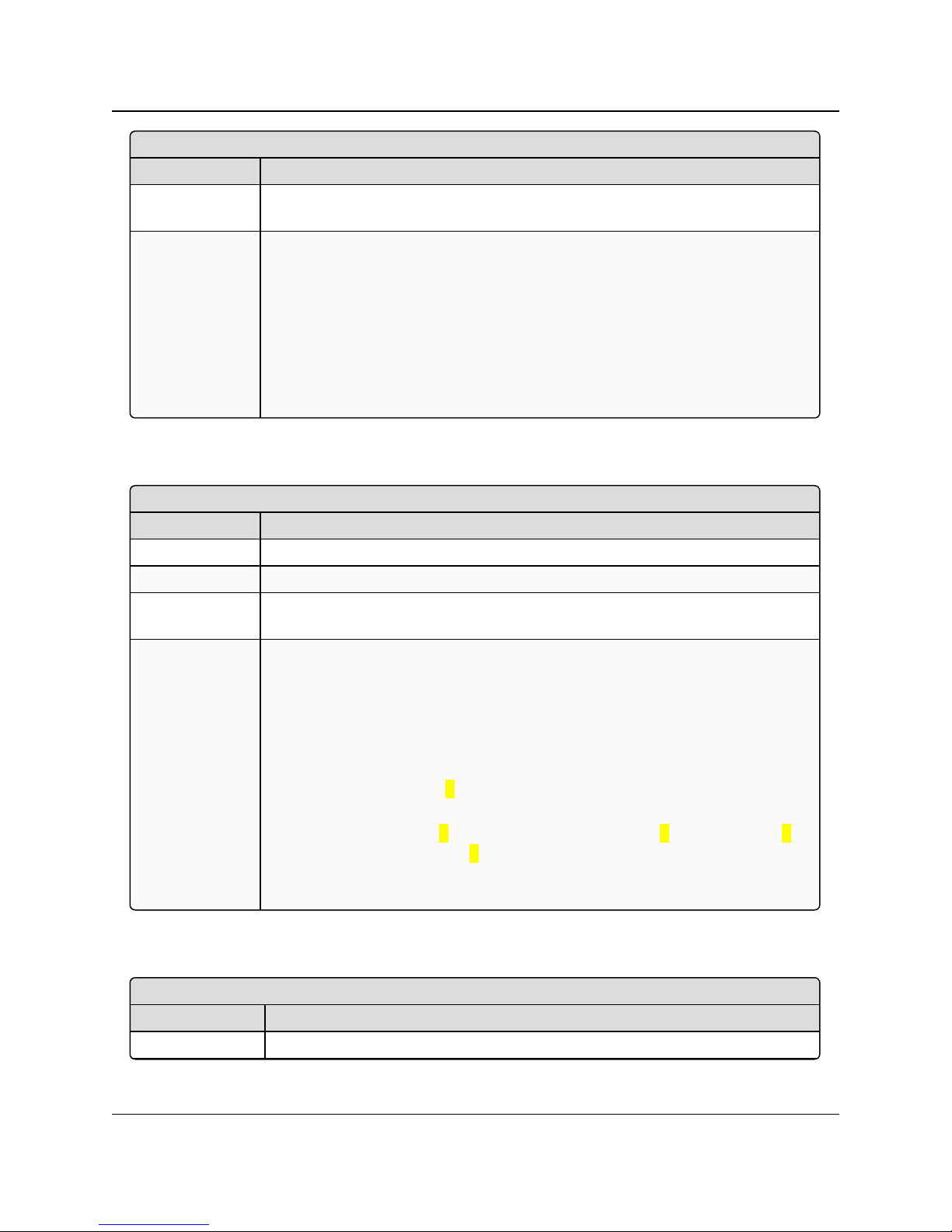
<Parameter Name>
Setting Description
Default Setting The factory default setting for the parameter.
Options The options the parameter can be set to.
Setup Terminal
Menu
The menu path and field name to access the parameter using the terminal menus
available through the serial port.
Description A description of what the parameter is and how it applies to the radio in the
network.
l Parameter setting text appears as: [Page=radioSettings]
l File names appear as: configuration.cfg.
l File paths appear as: C:\Program Files (x86)\FreeWave Technologies.
l User-entered text appears as: xxxxxxxxx.
rd
l 3
-party names appear as: Notepad®.
LRS455-C-U, -T-U, CE-U, TE-U
Caution: Indicates a situation that may cause damage to personnel, the radio, data, or
network.
Example: Provides example information of the related text.
FREEWAVE Recommends: Identifies FreeWave recommendation information.
Important!: Provides crucial information relevant to the text or procedure.
User & Reference Manual
Note: Emphasis of specific information relevant to the text or procedure.
Provides time saving or informative suggestions about using the product.
Warning! Indicates a situation that will cause damage to personnel, the radio, data, or
network.
Parameter Preference Table
The Parameter Preference table describes the parameter, its options, and usage.
LUM0016AB Rev May-2018 Page 8 of 90 Copyright © 2018FreeWave
This document is the property of FreeWave Technologies, Inc. and contains proprietary information owned by
FreeWave. This document cannot be reproduced in whole or in part by any means without written permission from
FreeWave Technologies, Inc.
Page 9
LRS455-C-U, -T-U, CE-U, TE-U
User & Reference Manual
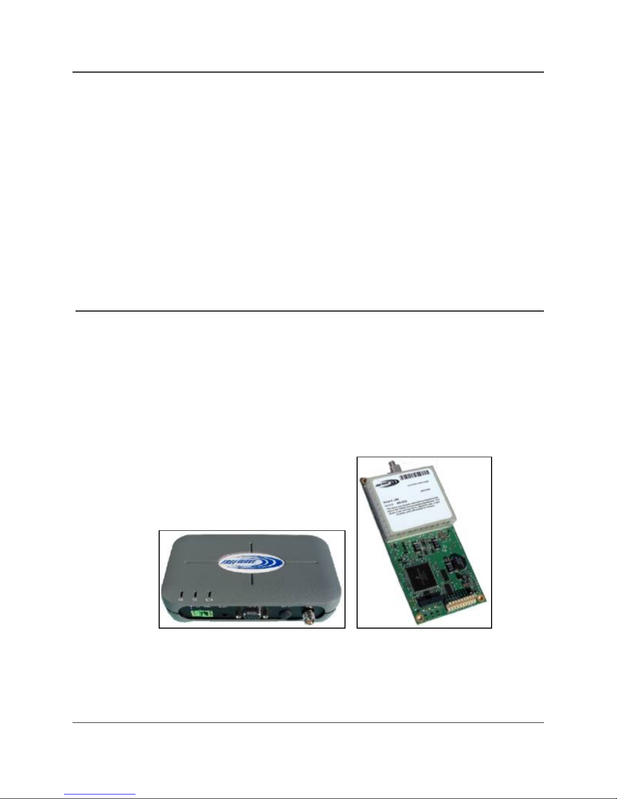
1. Introduction
FreeWave radios operate in virtually any environment where serial data communications occur. A
pair of radios functions as a 9-pin null modem cable.
l If the FreeWave radios are to be used in an application where a null modem cable is used,
such as communication between two computers, then the FreeWave radios can be
connected directly.
l If FreeWave radios are to be used to replace a straight-through RS232 cable, then a null
modem cable must be placed between the radio (DCE) and the DTE instrument to which it
is connected.
Figure 1: LRS455 Wireless Data Radio
LUM0016AB Rev May-2018 Page 9 of 90 Copyright © 2018FreeWave
This document is the property of FreeWave Technologies, Inc. and contains proprietary information owned by
FreeWave. This document cannot be reproduced in whole or in part by any means without written permission from
FreeWave Technologies, Inc.
Page 10
1. Introduction
Warning! Do not connect the LRS455-C-U, -T-U, CE-U, TE-U series radios to DC power
without terminating the antenna port to a suitable load, such as a 50 ohm antenna, or an
attenuator with a power rating greater than or equal to 2 W. Powering up without a load attached
will damage the radio and void the warranty.
LRS455-C-U, -T-U, CE-U, TE-U
User & Reference Manual
1.1. Choosing a Location for the Radios
Placement of the FreeWave radio is likely to have a significant impact on its performance. The key
to the overall robustness of the radio link is the height of the antenna. In general, FreeWave units
with a higher antenna placement will have a better communication link. In practice, the radio
should be placed away from computers, telephones, answering machines, and other similar
equipment. The cable included with the radio usually provides ample distance for placement away
from other equipment. FreeWave offers directional and Omni-directional antennas with cable
lengths ranging from 3 to 200 feet. When using an external antenna, placement of that antenna is
critical to a solid data link. Other antennas in close proximity are a potential source of interference.
Use the Radio Statistics to help identify potential problems.
The Show Radio Statistics page is found in option 4 in the main Setup menu or in the Diagnostic
information in Tool Suite. An adjustment as little as 2 feet in antenna placement can resolve some
noise problems. In extreme cases, such as when interference is due to a Pager or Cellular
Telephone tower, the band pass filters that FreeWave offers may reduce this out-of-bandnoise.
1.2. Choosing Point-to-Point or Point-to-MultiPoint Operation
Note: In an LRS455-C-U, -T-U, CE-U, TE-U radio network, you can use only one Repeater.
A Point-to-Point network is best suited when your network consists of one Master and one Slave
radio.
Important!: Adding a Repeater to a network reduces the throughput by 50%. For example, over-the-
air throughput in a network running at 2-Level GFSK and with the Repeaters parameter disabled is
9600 bps. With the Repeaters parameter enabled, the over-the-air throughput drops to 4800 bps.
The LRS455-C-U, -T-U, CE-U, TE-U radios are narrowband radios and have a limited channel size
based on the license obtained from the FCC. Therefore, the radios can experience a dramatic impact
in throughput if a Repeater is implemented in the network. If you have large amounts of data to
transfer and choose to add a Repeater in your network, you must optimize polling host / RTU
settings to accommodate for the lower throughput. Polling host / RTU optimization settings include
reducing block/packet sizes and increasing overall time-out parameters.
In a Point-to-MultiPoint network (also referred to as MultiPoint network), the Master radio is able
to simultaneously communicate with numerous Slave radios. In its simplest form, a MultiPoint
network functions with the Master broadcasting its messages to all Slaves. If requested by the
Master, the Slaves respond to the Master when given data by the device connected to the data
port. This response depends on your setup. You can extend the reach of a licensed network with
LUM0016AB Rev May-2018 Page 10 of 90 Copyright © 2018FreeWave
This document is the property of FreeWave Technologies, Inc. and contains proprietary information owned by
FreeWave. This document cannot be reproduced in whole or in part by any means without written permission from
FreeWave Technologies, Inc.
Page 11

1. Introduction
LRS455-C-U, -T-U, CE-U, TE-U
User & Reference Manual
one Repeater. As with a Repeater in a Point-to-Point network, adding a Repeater to a network
cuts the data throughput by half.
It is important to note the differences between Point-to-Point and MultiPoint networks. In a Pointto-Point network all packets are acknowledged, whether sent from the Master to the Slave or from
the Slave to the Master. In a MultiPoint network, you determine the number of times outbound
packets from the Master or Repeater to Slaves are sent. The receiving radio, Slave or Repeater,
accepts the first packet received that passes the 32 bit CRC. However, the packet is not
acknowledged. On the return trip to the Master, all packets sent are acknowledged or
retransmitted until they are acknowledged. Therefore, the return link in a MultiPoint network is
very robust.
Traditionally, a MultiPoint network is used in applications where data is collected from many
instruments and reported back to one central site. The architecture of such a network is different
from Point-to-Point applications. The following parameters influence the number of radios that
can exist in a MultiPoint network:
1. Size of the blocks of data. The longer the data blocks, the fewer number of deployed Slaves
can exist in the network.
2. Baud rate. The data rate between the radio and the device to which it is connected could
limit the amount of data and the number of radios that can exist in a network
3. The amount of contention between Slaves. Polled Slaves vs. timed Slaves.
4. Use of a Repeater. Using the Repeaters setting in a MultiPoint network decreases overall
network capacity by 50%.
Example: If the network polls Slaves once a day to retrieve sparse data, several hundred Slaves
could be configured to a single Master. However, if each Slave transmits larger amounts of data or
data more frequently, then fewer Slaves can link to the Master while receiving the same network
performance. When larger amounts of data are sent more frequently, the overall network bandwidth
is closer to capacity with fewer Slaves.
For examples and additional information about data communication links, see the Data
Communication Links section.
1.3. Data Communication Link Examples
FreeWave radios' versatility allows data communication links to be established using a variety of
different configurations.
1.3.1. Point to Point Link
The example below shows the most common and straight forward link; a Master communicating
to a Slave in a Point-to-Point link.
Figure 2: Point to Point Link
LUM0016AB Rev May-2018 Page 11 of 90 Copyright © 2018FreeWave
This document is the property of FreeWave Technologies, Inc. and contains proprietary information owned by
FreeWave. This document cannot be reproduced in whole or in part by any means without written permission from
FreeWave Technologies, Inc.
Page 12
1. Introduction
LRS455-C-U, -T-U, CE-U, TE-U
User & Reference Manual
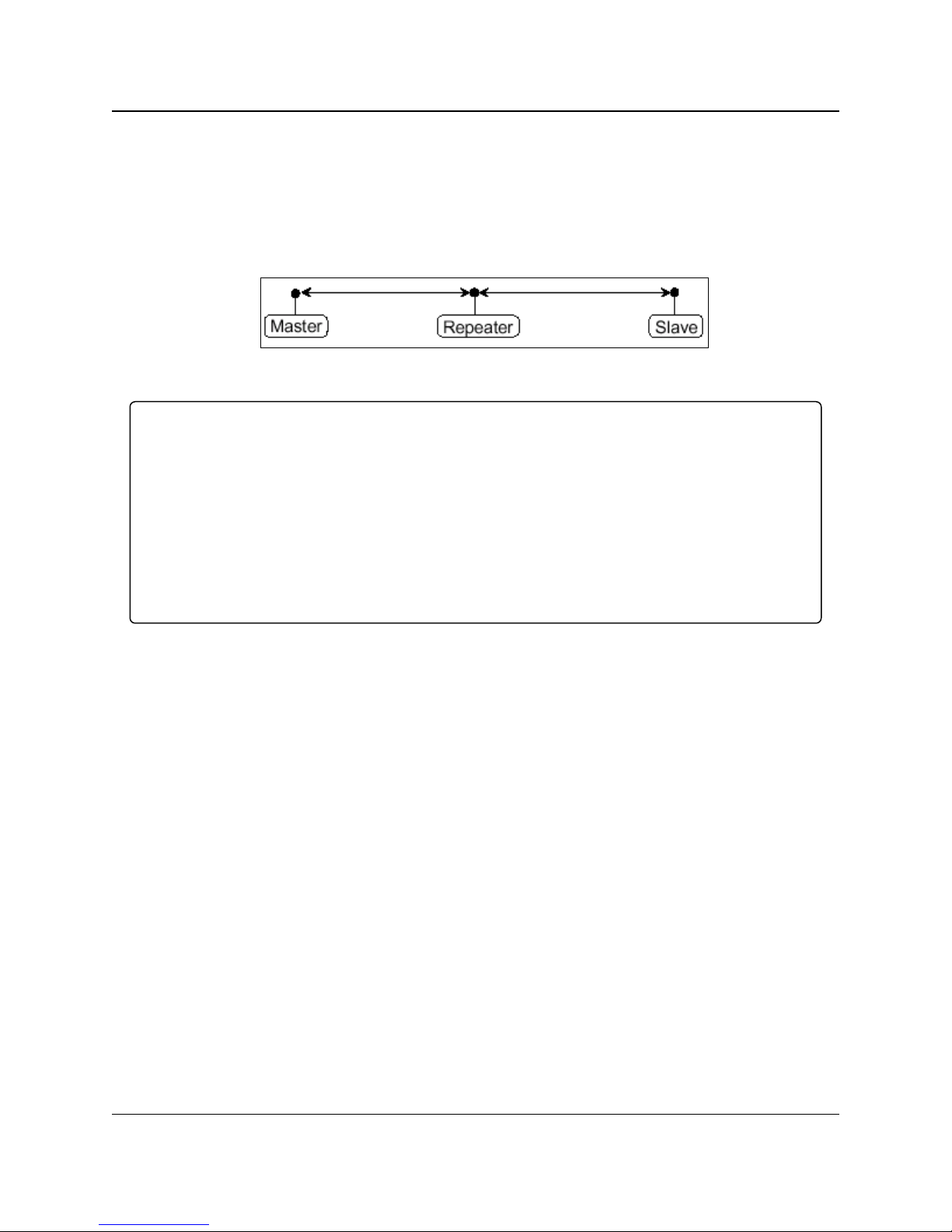
1.3.2. Repeater Link
The example below shows how a link might be set up using a Repeater. The Repeater may be
located on a hilltop or other elevated structure enhancing the link from the Master to the Slave.In
this configuration, it may be desirable to use an external Omni directional antenna at the
Repeater.Yagi antennas may be used at both the Master and Slave radios.
In an LRS455-C-U, -T-U, CE-U, TE-U radio network, you can use only one Repeater.
Figure 3: Repeater Link
Important!: Adding a Repeater to a network reduces the throughput by 50%. For example, over-the-
air throughput in a network running at 2-Level GFSK and with the Repeaters parameter disabled is
9600 bps. With the Repeaters parameter enabled, the over-the-air throughput drops to 4800 bps.
The LRS455-C-U, -T-U, CE-U, TE-U radios are narrowband radios and have a limited channel size
based on the license obtained from the FCC. Therefore, the radios can experience a dramatic impact
in throughput if a Repeater is implemented in the network. If you have large amounts of data to
transfer and choose to add a Repeater in your network, you must optimize polling host / RTU
settings to accommodate for the lower throughput. Polling host / RTU optimization settings include
reducing block/packet sizes and increasing overall time-out parameters.
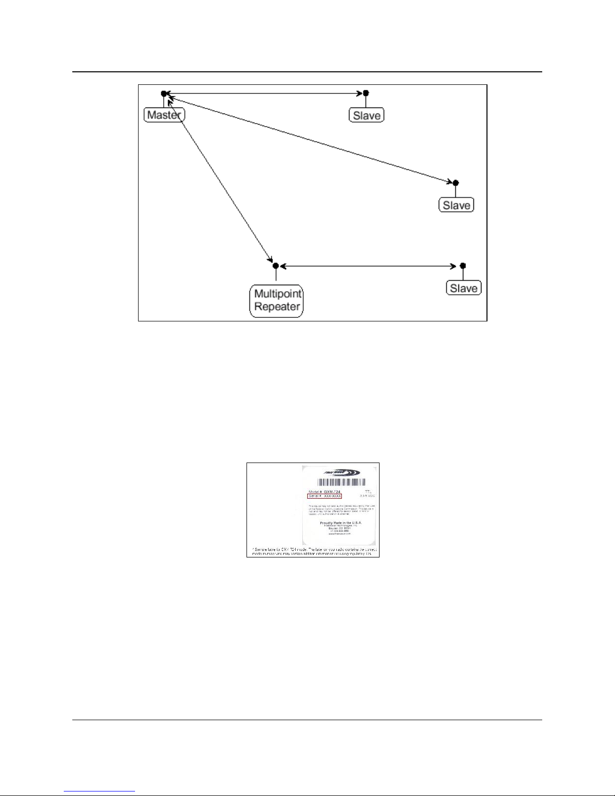
1.3.3. Point to Multipoint Network
The next example depicts a standard Point-to-MultiPoint network. From the Master, any data is
broadcast to all three Slaves, one of which receives it through a MultiPoint Repeater. The data is
in turn sent out of the serial port of each of the three Slaves. The end device should be configured
to interpret the serial message and act on it if necessary.
LUM0016AB Rev May-2018 Page 12 of 90 Copyright © 2018FreeWave
This document is the property of FreeWave Technologies, Inc. and contains proprietary information owned by
FreeWave. This document cannot be reproduced in whole or in part by any means without written permission from
FreeWave Technologies, Inc.
Page 13
1. Introduction
LRS455-C-U, -T-U, CE-U, TE-U
User & Reference Manual
Figure 4: Point to Multipoint Link
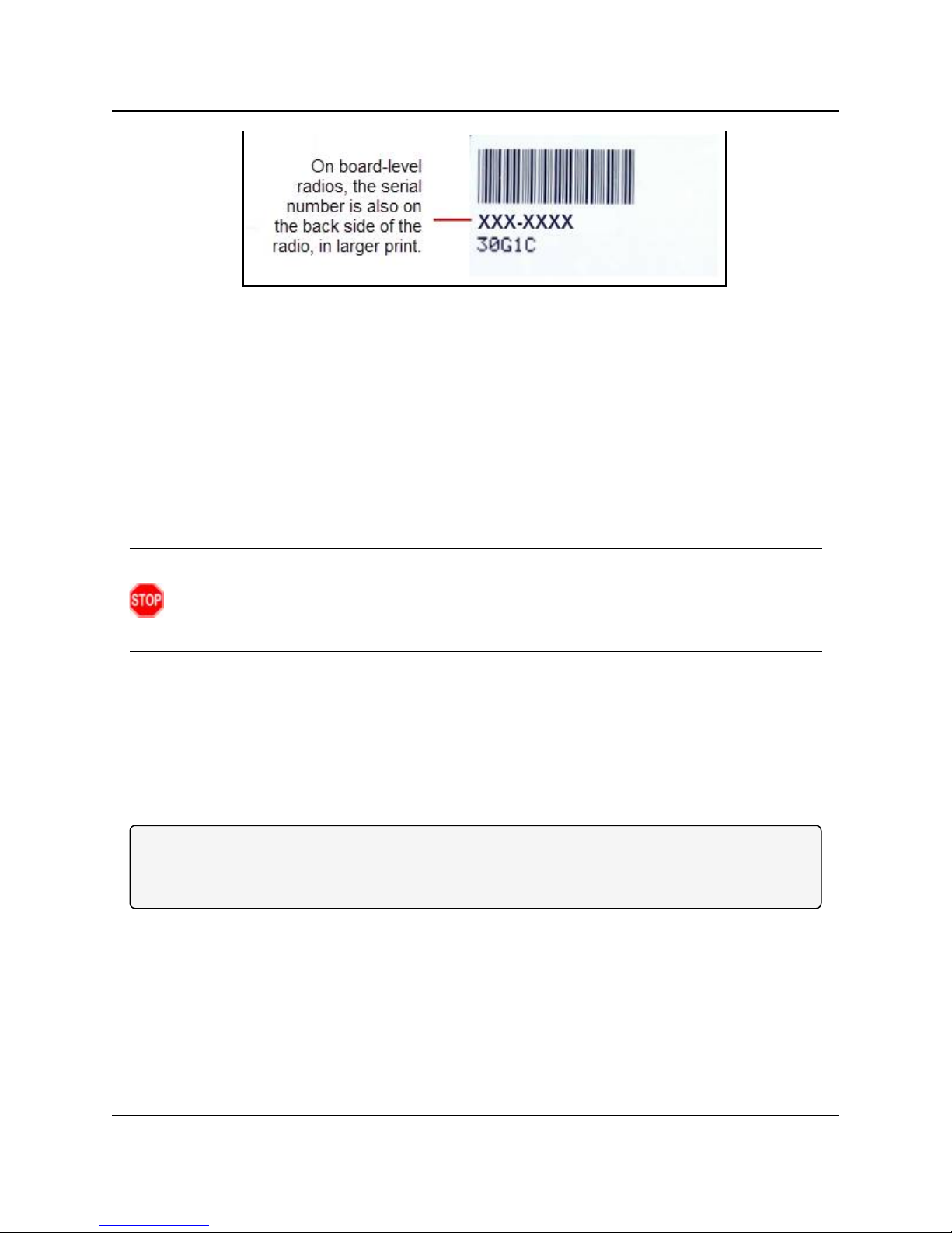
1.4. Finding the Product Serial Number
Each FreeWave radio is assigned a unique serial number. If you need to contact FreeWave
Technical Support, you will be asked for the serial number on the radio you are calling about.
The serial number is three digits, followed by a hyphen and four digits, for example 111-1111, and
is printed on the FreeWave label on the radio. The example below is for a GXM model; however,
the serial number information will be in the same location on different models.
Figure 5: Serial Number Location for Enclosed Model
On radios that are not in an enclosure, you can also find the serial number printed on a label on the
back (the flat, smooth side) of the radio. This label is in larger print.
LUM0016AB Rev May-2018 Page 13 of 90 Copyright © 2018FreeWave
This document is the property of FreeWave Technologies, Inc. and contains proprietary information owned by
FreeWave. This document cannot be reproduced in whole or in part by any means without written permission from
FreeWave Technologies, Inc.
Page 14
1. Introduction
LRS455-C-U, -T-U, CE-U, TE-U
User & Reference Manual
Figure 6: Serial Number Location for Non-Enclosed Model
1.5. Powering the Radio
To provide power to the radio, connect it to a positive supply with +6.0 to +27.0 VDC (typically,
+12VDC).
Using a dedicated power supply line is preferred. The power supply you use must provide more
current than the amount of current drain listed in the product specifications listed in the product's
data sheet available on www.FreeWave.com for the voltage you are using. For example, if you
are using +12.0VDC, the power supply must provide above the drain that is required for transmit
using +12 VDC.
Warning! Do not connect the LRS455-C-U, -T-U, CE-U, TE-U series radios to DC power
without terminating the antenna port to a suitable load, such as a 50 ohm antenna, or an
attenuator with a power rating greater than or equal to 2 W. Powering up without a load attached
will damage the radio and void the warranty.
If the power supply line runs outside the radio enclosure, use electrostatic discharge (ESD)
protectors to protect the radio from electric shock, and transient voltage suppressors (TVS) to
protect from an over-voltage situation. Using both helps to ensure long-term, reliable operation.
FreeWave does not supply or sell these items; however, they can be purchased at most electronic
supply stores.
1.6. Configuration Tool Options
Note: The terms modem and radio are used interchangeably in this document and in the text within
the setup tools. While the words have different meanings, the two terms should be treated as one
and the same when referring to FreeWave products.
When the radio is in Setup mode, you can use the following setup tools to configure the settings on
the radio:
l Tool Suite - provides a group of tools for configuring the devices in your network and for
monitoring your network's performance. Using the Configuration application within Tool
Suite, you can program changes to your radio's settings.
l Terminal Emulator - A terminal emulator program, e.g., TeraTerm, offers many of the
same configuration options that are available in the Configuration application in Tool Suite.
LUM0016AB Rev May-2018 Page 14 of 90 Copyright © 2018FreeWave
This document is the property of FreeWave Technologies, Inc. and contains proprietary information owned by
FreeWave. This document cannot be reproduced in whole or in part by any means without written permission from
FreeWave Technologies, Inc.
Page 15

1. Introduction
l You can use the terminal emulator program of your choice to program the radio. The
LRS455-C-U, -T-U, CE-U, TE-U
User & Reference Manual
Setup Terminal application in Tool Suite provides the same interface that is available
using a terminal emulator.
1.6.1. Tool Suite and Terminal Emulators
If using a terminal emulator, the tabs for a device in Tool Suite mirror the Setup main menu
selections.
Example: Option 0 from the Setup main menu in the terminal menu setup is Set Operation Mode.
The corresponding configuration tab for the device in Tool Suite is (0) Operation Mode.
Figure 7: Tool Suite and Setup Menu
You can also use the Setup Terminal application within Tool Suite to use and view the terminal
menus. It displays the same menus and provides the same programming settings as you see
using a terminal emulator.
Throughout this document, if the setup procedure in the terminal emulator is different than the
procedure in Tool Suite, the terminal instructions are also included.
1.7. Radio Setup Mode
To read the current settings from or to program a radio, the radio must be in Setup mode. When a
radio is in Setup mode, all three LEDs display solid green . See the sections below for
details about how to access the radio's Setup mode using Tool Suite or a terminal emulator.
Note: OEM boards may also enter Setup when Pin 2 on a 10-point connector or Pin 8 on a 24-pin
connector is grounded, or using a break command. For more information about the break command,
see Use Break to Access Setup (on page 28).
The Setup Port (on page 26) parameter in the Baud Rate tab determines whether the main data
port or the diagnostics port is used to access the setup parameters for the radio.
LUM0016AB Rev May-2018 Page 15 of 90 Copyright © 2018FreeWave
This document is the property of FreeWave Technologies, Inc. and contains proprietary information owned by
FreeWave. This document cannot be reproduced in whole or in part by any means without written permission from
FreeWave Technologies, Inc.
Page 16
1. Introduction
LRS455-C-U, -T-U, CE-U, TE-U
User & Reference Manual
Using the Setup Mode Timeout parameter in the Operation Mode tab, you can set the radio to
exit Setup Mode automatically. When the setting is enabled, if the radio has not received any
menu selections or programming information within 5 seconds, it exits Setup and resumes its
previous mode.
1.7.1. Using Tool Suite to Connect to and Program Radios
To read and program a radio using ToolSuite, you need to connect the radio to a desktop
computer or a laptop that runs the Tool Suite software.
1. Connect a serial or diagnostic cable between the computer or laptop and the radio.
FREEWAVE Recommends: Using a diagnostic cable is recommended.
2. Connect the power supply to the radio and the power source and turn on the radio.
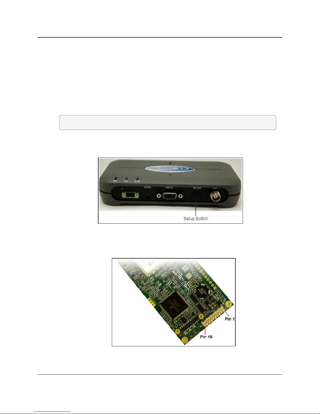
3. To place the radio in Setup mode, press the Setup button on the back of the FreeWave
radio. If connected to the diagnostics port, type <Shift+U> to activate the Setup menu.
To place the radio in Setup mode in board-level radios:
l Short pins 2 & 4 (Brown to Black) on the white 10 pin header next to the LEDs.
4.
LUM0016AB Rev May-2018 Page 16 of 90 Copyright © 2018FreeWave
This document is the property of FreeWave Technologies, Inc. and contains proprietary information owned by
FreeWave. This document cannot be reproduced in whole or in part by any means without written permission from
Figure 8: Setup Button
Figure 9: Pins 1 and 10
FreeWave Technologies, Inc.
Page 17

1. Introduction
Port Setting Select
Bits per second 19200
Data Bits 8
Parity None
StopBits 1
Flow Control None
l If using a Data Cable (FreeWave Part Number: ASC3610DB or ASC3610DJ), press
LRS455-C-U, -T-U, CE-U, TE-U
User & Reference Manual
the Setup button.
l If using the gray ribbon Diagnostic Cable (FreeWave Part Number: AC2009DC), or the
black Diagnostic Cable (FreeWave Part Number: ASC0409DC), type <Shift+U>.
All three LEDs on the radio light green and stay green as long as the radio is in
Setup mode.
5. With the radio connected to the computer and in Setup mode, inToolSuite, click
Configuration in the Application pane to display the Configuration application.
6. Click Read Radio in the Configuration ribbon to read the radio's current settings.
7. Make the necessary parameter changes and do one of the following to send the changes to
the radio:
l To send only the parameters you have changed, within the Configuration application, in
the Network Title ribbon, click Quick.This option is only available if you clicked Read
Radio and are not sending parameter settings from a template to the radio.
l To send all the settings for all parameters, within the Configuration application, in the
Network Title ribbon, click All.
l To set a device back to its factory default settings, within the Configuration application,
in the Network Title ribbon, click Default.
1.7.2. Accessing the Setup Menu using a Terminal Emulator
Use a terminal emulator of your choice to access the Setup menu. For any terminal emulator
application, plug the serial cable into a com port on the radio, open a session and ensure that the
port settings are set to the following for a proper connection to the radio:
The instructions describe how to access the radio's Setup menu using the Setup Terminal
application in Tool Suite. Setup Terminal contains the port settings above, by default.
1. Plug a serial cable into Com 1 and connect it to the computer running Tool Suite and
connect the radio to power.
2. OpenTool Suite.
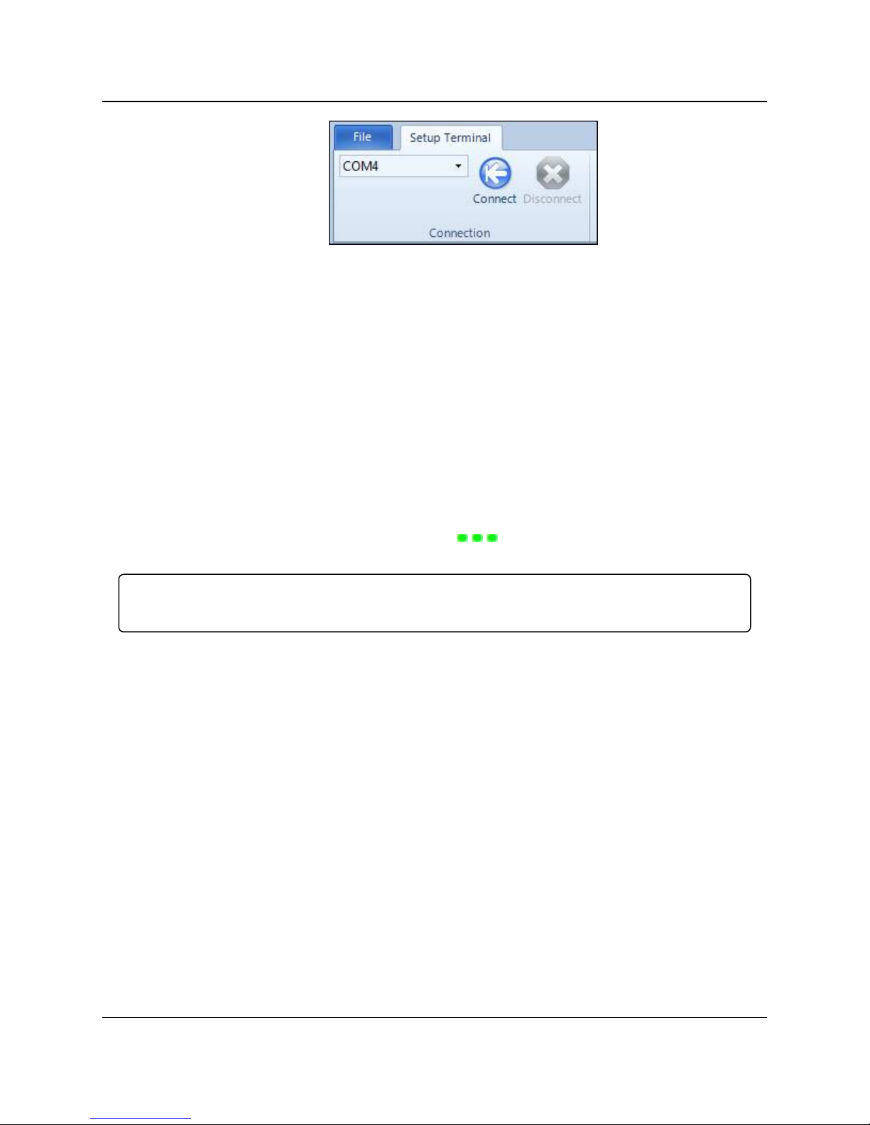
3. Select Setup Terminal in the Applications pane.
4. From the drop-down list at the top left of the window, select the Com port on the computer
to which the radio is connected.
LUM0016AB Rev May-2018 Page 17 of 90 Copyright © 2018FreeWave
This document is the property of FreeWave Technologies, Inc. and contains proprietary information owned by
FreeWave. This document cannot be reproduced in whole or in part by any means without written permission from
FreeWave Technologies, Inc.
Page 18
1. Introduction
LRS455-C-U, -T-U, CE-U, TE-U
User & Reference Manual
Figure 10: Tool Suite Connect button
5. Click Connect.
6. To connect to the radio, in enclosed radios, press the Setup button on the back of the
FreeWave radio. If connected to the diagnostics port, type U (Capital ‘U’) to invoke the
Setup menu.
To display the Setup menu in board level radios:
l Short pins 2 & 4 (Brown to Black) on the 10 pin header next to the LEDs.
l If using a data cable (FreeWave Part Number: ASC3610DB or ASC3610DJ), press
the Setup button.
l If using the gray ribbon diagnostic cable (FreeWave Part Number: AC2009DC) or the
black diagnostic cable (P/N ASC0409DC), type <Shift+U> to activate the Setup menu.
When Setup is activated, the FreeWave Setup Main Menu shows in the terminal emulator
window. All three LEDs on the radio light green and stay green as long as the radio is in
Setup mode. The main setup menu appears.
Important!: As you navigate through the Setup menu and make changes to the parameters, the
parameters are sent to the radio immediately.
1.7.3. Troubleshooting Terminal Emulators
These are some common issues encountered while using terminal emulators:
Nothing displays on the screen after placing the radio into Setup mode.
This usually indicates one of two things; either the wrong Com port is selected or a null
modem cable is being used. Change the Com port, verify the cable, and attempt to
connect again.
In addition, if the radio has been previously configured, you could be using the wrong
port to access the Setup menu. For more information, see Setup Port (on page 26).Try
connecting to the other port.
Unreadable characters display on the screen after placing the radio into Setup mode.
This typically indicates a baud rate mismatch. Unreadable characters before
grounding the pin indicates Diagnostics is enabled and the terminal emulator is
connected to the Diagnostics pins. Update the terminal emulator's baud rate to 19200
and reconnect to the radio.
LUM0016AB Rev May-2018 Page 18 of 90 Copyright © 2018FreeWave
This document is the property of FreeWave Technologies, Inc. and contains proprietary information owned by
FreeWave. This document cannot be reproduced in whole or in part by any means without written permission from
FreeWave Technologies, Inc.
Page 19

1. Introduction
LRS455-C-U, -T-U, CE-U, TE-U
User & Reference Manual
The Setup menu displays on the screen, but nothing happens when keys on the
keyboard are pressed.
This usually indicates flow control is turned on in a three-wire connection (Rx, Tx, and
Gnd). Update the terminal emulator's flow control setting to None and reconnect to the
radio.
A connection exists, the terminal emulator is receiving data, and some data is correct,
but the remaining data is in unrecognizable characters.
This usually indicates a parity mismatch. Ensure that the parity of the radio and the
parity of emulator are are set the same.
1.8. Upgrading Radios to the Latest Firmware
If Tool Suite is connected to a radio, and a new version of the firmware is available for that radio
model, an indication displays within the Configuration application's Device Information tab. You
can use Tool Suite to upgrade firmware on a serial radio that is connected directly to the computer
using the diagnostic cable. You cannot complete an over-the-air upgrade using Tool Suite.
Note: If you are using a USB-to-serial converter cable, a firmware upgrade can take a long time to
complete. FreeWave recommends using only USB-to-serial cables that include the FTDI Chip Set.
This inclusion is listed on the cable's packaging.
Use the steps below to upgrade a radio to the latest firmware:
1. With the radio connected to your computer through the Com port, open Tool Suite and click
Configuration in the Applications pane to display the Configuration application.
2. Click Upgrade Radio in the Firmware section of the Configuration ribbon.
3. Click Yes at the prompt to proceed or No to cancel without installing the new firmware.
Tool Suite identifies and displays the firmware version that is loaded on the connected
device and displays the latest version of firmware available for that model.
4. Click Yes to proceed with the upgrade, or No to exit.
The system displays the progress of the firmware upgrade. After the firmware upgrade is
complete, a message displays that the firmware upgrade was successful.
LUM0016AB Rev May-2018 Page 19 of 90 Copyright © 2018FreeWave
This document is the property of FreeWave Technologies, Inc. and contains proprietary information owned by
FreeWave. This document cannot be reproduced in whole or in part by any means without written permission from
FreeWave Technologies, Inc.
Page 20

LRS455-C-U, -T-U, CE-U, TE-U
User & Reference Manual
2. Basic Radio Programming and Setup
As you set up your network, whether it be a Point-to-MultiPoint network or a Point-to-Point
network, the process for setting up and programming a radio is the same. This chapter describes
the following aspects of programming and setting up a radio, regardless of the network type:
l Setting the radio's role in the network, and the network type.
l Entering parameters that establish communication with the instrument or computer to
which the radio is connected.
l Establishing communication with other radios in the network.
l Setting data transmission characteristics.
2.1. Setting the Radio's Role in the Network and the Network
Type
Radio networks consist of a Master and any number of other components including Repeaters,
Slave radios, and radio's that act as both Slave and a Repeater radio. The first parameter to set in
a radio is to select its Operation Mode or Modem Mode. The mode tells the radio what network
type it is in (Point-to-Point or Point-to-MultiPoint) and what role it plays, Master, Slave, or
Repeater, in that network.
Note: The network type must match for all radios in a network. For example, if you are configuring a
Point-to-MultiPoint network, ensure the Modem Mode selection for radios in the network starts with
Point-to-MultiPoint.
In a Point-to-Point configuration, Master or Slave mode may be used on either end of the
communication link without performance degradation. When setting up the radio, remember that
the settings on the Master control a number of parameters. Therefore, deploying the Master on
the communications end where it is easier to access is advised, but not necessary.
LUM0016AB Rev May-2018 Page 20 of 90 Copyright © 2018FreeWave
This document is the property of FreeWave Technologies, Inc. and contains proprietary information owned by
FreeWave. This document cannot be reproduced in whole or in part by any means without written permission from
FreeWave Technologies, Inc.
Page 21

2. Basic Radio Programming and Setup
Operation Mode Description
Point-to-Point Master
(0)
This mode designates the radio as the Master in Point-to-Point mode. The
Master may call any or all Slaves designated in its Call Book.
In Point-to-Point mode the Master determines the setting used for most of the
radio transmission characteristics, regardless of the settings in the Slave
and/or Repeater. The settings not determined by the Master are:
l Transmit Power
l Slave Security
l Retry Time Out
l Hop Table settings
To identify a Master, power the radio. Prior to establishing a communication
link with a Slave, all three of the Master's LEDs are solid red.
Point-to-Point Slave
(1)
This mode designates the radio as a Slave in Point-to-Point mode. The Slave
communicates with any Master in its Call Book—either directly or through
one Repeater.
When functioning as a Slave, the Entry to Call feature in the radio’s Call Book
is not operational.
Set Slave Security to 1 to bypass the Call Book in the Slave. For more
information, see Slave Security (on page 37).
Point–to-MultiPoint
Master (2)
This mode designates the radio as a Master in MultiPoint mode. This mode
allows one Master to communicate simultaneously with numerous Slaves.
A Point-to-MultiPoint Master communicates only with other radios
designated as Point-to-MultiPoint Slaves or Point-to-MultiPoint Repeaters.
Point-to- MultiPoint
Slave (3)
This mode designates the radio as a Slave in MultiPoint mode. This mode
allows the Slave to communicate with a MultiPoint Master. The Slave may
communicate with its Master through one Repeater.
Point-to-Point
Slave/Repeater (4)
This mode designates the radio to act as either a Slave or Repeater—
depending on the instructions from the Master. The radio cannot act as both a
Slave and a Repeater at the same time. True Slave/Repeater functionality is
only available in a MultiPoint mode.
Point-to-Point Slave/Repeaters have no security features. When a radio is
designated a Point-to-Point Slave/Repeater, it allows any Master to use it as
a Repeater.
Point-to-Point
Repeater (5)
A network using LRS455-C-U, -T-U, CE-U, TE-U radios can have one
Repeater in a Point-to-Point communications link, to extend the operating
range. When designated as a Repeater, a radio behaves as a pass-through
link. All settings for the Call Book, baud rates, and radio transmission
characteristics are disabled. A Repeater connects with any Master that calls
it. The Repeater must be set up properly in the Master's Call Book.
Set the Modem Mode in the Operation Mode tab, using the Modem Mode field. These settings
are available in the Operation Mode menu in the terminal interface. Select from these options:
LRS455-C-U, -T-U, CE-U, TE-U
User & Reference Manual
FreeWave. This document cannot be reproduced in whole or in part by any means without written permission from
LUM0016AB Rev May-2018 Page 21 of 90 Copyright © 2018FreeWave
This document is the property of FreeWave Technologies, Inc. and contains proprietary information owned by
FreeWave Technologies, Inc.
Page 22

2. Basic Radio Programming and Setup
Operation Mode Description
Point-to-Point
Slave/Master
Switchable (6)
Mode 6 allows the radio to be controlled entirely through software commands.
A number of key parameters in the FreeWave user interface may be changed
either directly with a program such as Windows Terminal or through the use
of script files. Additionally, when the Point-to-Point Slave/Master Switchable
option is selected and the radio is not calling a Slave, it functions as a Slave
and accepts any appropriate calls from other radios.
For more information, see Application Note #5476, Mode 6.
Point-to-MultiPoint
Repeater (7)
This mode allows the radio to operate as a Repeater in a MultiPoint network.
You can have one Repeater in an LRS455-C-U, -T-U, CE-U, TE-U network.
Ethernet Options (F) This menu applies to Ethernet radios only. Although the menu is included
here, it is unrelated to this radio.
Baud Rate
Setting Description
Default Setting 115200
Options 1200, 2400, 4800, 9600, 19200, 38400, 57600, 76800, 115200, 230400
Setup Terminal
Menu
(1) Set Baud Rate
LRS455-C-U, -T-U, CE-U, TE-U
User & Reference Manual
2.2. Establishing Communication with Instrumentation and
Computers
The settings in the Baud Rate tab are the communication settings between the radio and the
instrument or computer to which it is connected (radio serial port to the device). These settings are
unique to each radio, and do not need to match across the network.
For example, a pair of radios may be used in an application to send data from remote process
instrumentation to an engineer's computer. In this application, the baud rate for the radio on the
instrumentation might be set to 9600, and the radio on the polling host might be set to 57,600.
Set the following parameters in the Baud Rate tab. These settings are available in the Baud Rate
menu in the terminal interface, and apply to both Point-to-Point and Point-to-MultiPoint networks.
2.2.1. Baud Rate
FreeWave. This document cannot be reproduced in whole or in part by any means without written permission from
LUM0016AB Rev May-2018 Page 22 of 90 Copyright © 2018FreeWave
This document is the property of FreeWave Technologies, Inc. and contains proprietary information owned by
FreeWave Technologies, Inc.
Page 23

2. Basic Radio Programming and Setup
Baud Rate
Setting Description
Description This is the actual baud rate for the radio’s data port.
l This setting is the communication rate between the radio and the instrument to
which it is connected, and is independent of the baud rate for the other radios
in the network.
l Set the baud rate to the highest level supported by the device to which it is
connected.
l With a poor radio link, however, this may actually result in slower data
communications.
Example: A pair of radios may be used in an application to send data from
remote process instrumentation to the engineer's computer. In this
application, the baud rate for the radio on the instrumentation might be set
to 9600, and the radio on the engineer's computer might be set to 57,600.
FREEWAVE Recommends: With a Baud Rate setting of 9600 or higher,
FreeWave recommends using the Flow Control lines. For more
information, see Flow Control (on page 24).
Note: The setup port Baud Rate always defaults to 19,200 regardless of
how the data port Baud Rate is set. The only exception is Mode 6. For
more information, see application note #5476, Mode 6.
Data Parity
Setting Description
Default Setting 0 (8, N, 1)
Options See table below
Setup Terminal
Menu
(1) Set Baud Rate > (A) Data Parity
LRS455-C-U, -T-U, CE-U, TE-U
User & Reference Manual
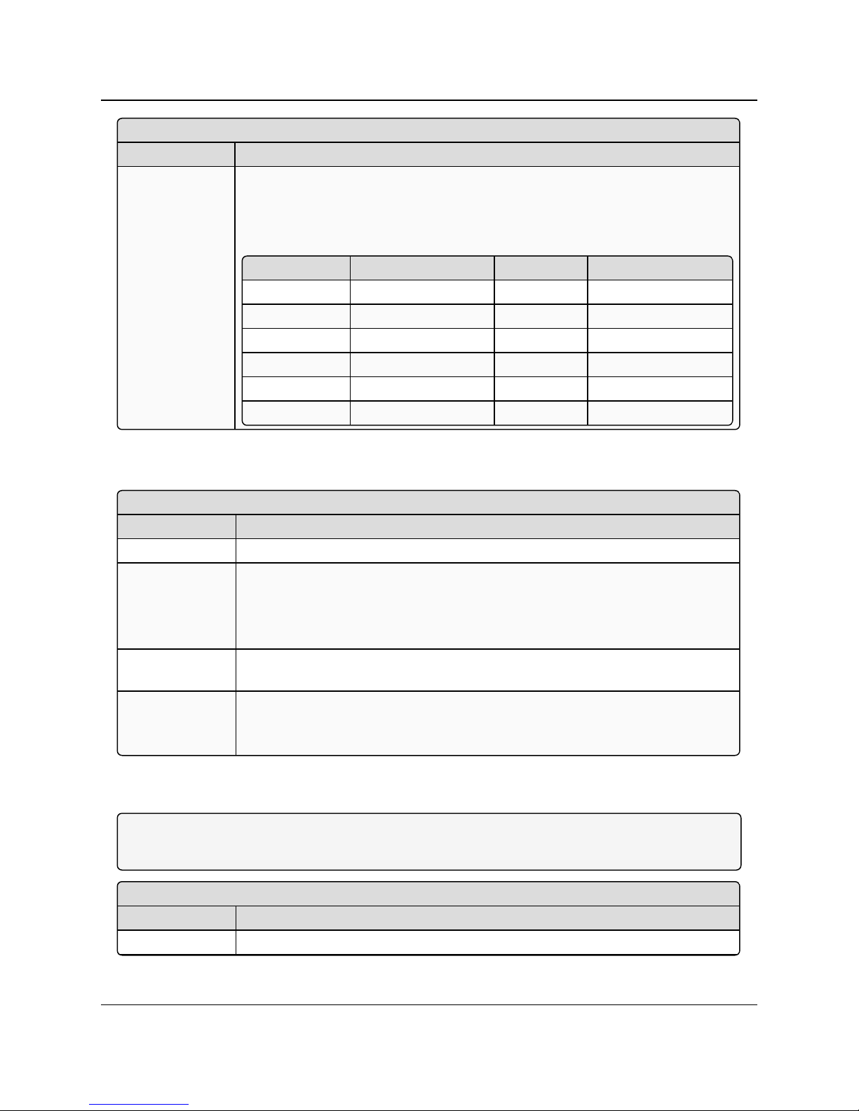
2.2.2. Data Parity
FreeWave. This document cannot be reproduced in whole or in part by any means without written permission from
LUM0016AB Rev May-2018 Page 23 of 90 Copyright © 2018FreeWave
This document is the property of FreeWave Technologies, Inc. and contains proprietary information owned by
FreeWave Technologies, Inc.
Page 24
2. Basic Radio Programming and Setup
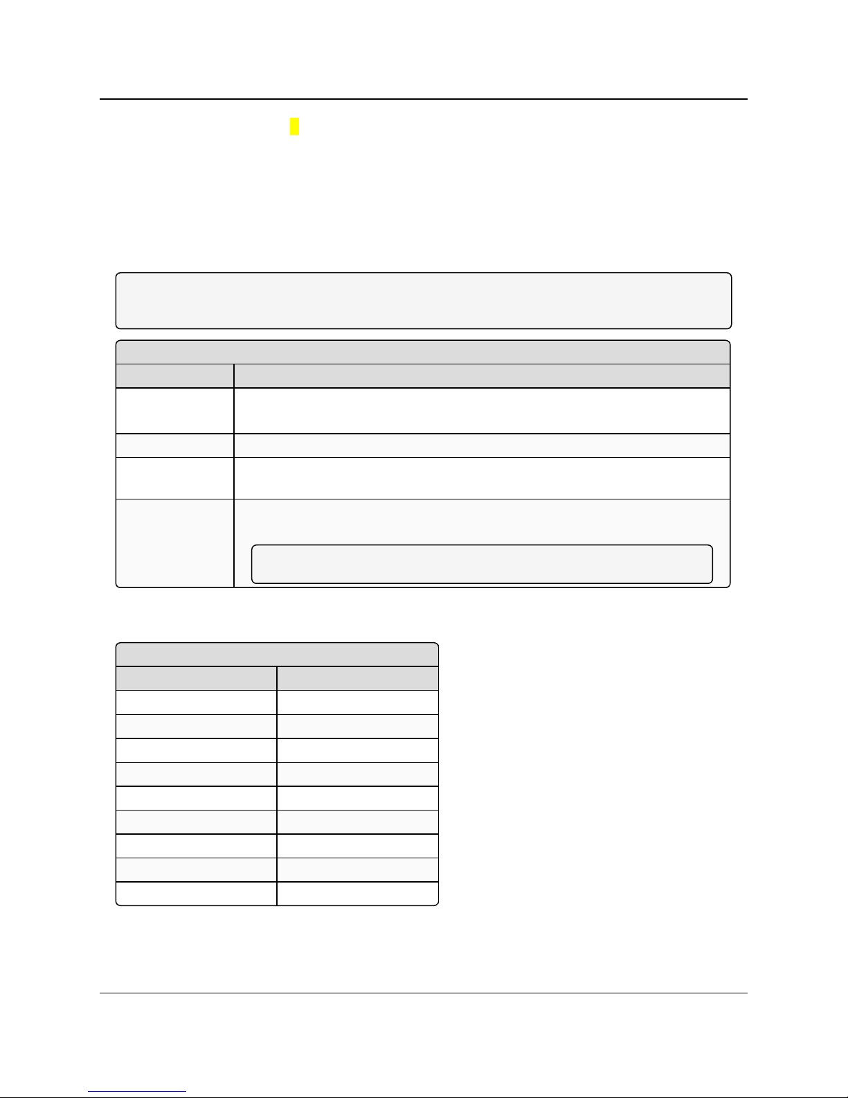
Data Parity
Setting Description
Description Six data word length and parity configurations are available for use with FreeWave
radios. The default setting is 8-None-1 and is the most commonly used serial
communications protocol.
The following table describes each option:
Option Data Bits Parity Stop Bits
0 8 None 1
1 7 Even 1
2 7 Odd 1
3 8 None 2
4 8 Even 1
5 8 Odd 1
Flow Control
Setting Description
Default Setting (0) None
Options l (0) None - No flow control CTS is active and de-asserts when buffering in 98%
full. Can pass XON/XOFF data but does not use it in any way.
l (1) RTS - Uses standard RTS/CTS control lines.
l (2) DTR
Setup Terminal
Menu
(2) Set Baud Rate > (F) FlowControl
Description Specifies the hardware flow control for the data port on the radio.
FreeWave recommends using Flow Control if you are using a baud rate higher
than 9600 bps in a narrow-band licensed network.
Modbus RTU
Setting Description
Default Setting 0 (Disabled)
2.2.3. Flow Control
LRS455-C-U, -T-U, CE-U, TE-U
User & Reference Manual
2.2.4. Modbus RTU
Note: When using the radio in Modbus RTU mode, the Master Packet Repeat setting must match in
every radio, regardless of whether the network is in Point-to-Point or MultiPoint mode.
LUM0016AB Rev May-2018 Page 24 of 90 Copyright © 2018FreeWave
This document is the property of FreeWave Technologies, Inc. and contains proprietary information owned by
FreeWave. This document cannot be reproduced in whole or in part by any means without written permission from
FreeWave Technologies, Inc.
Page 25
2. Basic Radio Programming and Setup
Modbus RTU
Setting Description
Options Any number between 0 to 9
Setup Terminal
Menu
(1) Set Baud Rate > (B) ModbusRTU
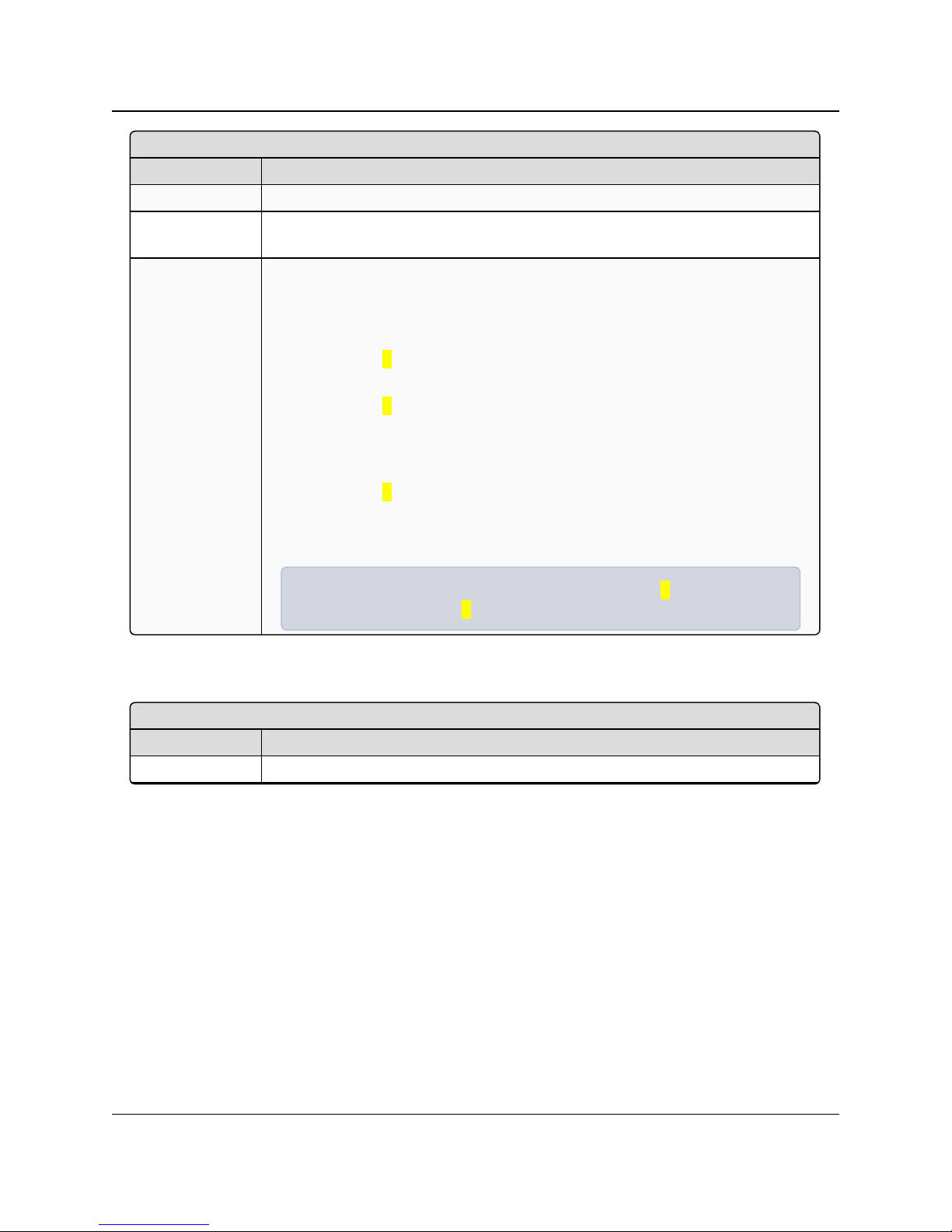
Description The Modbus RTU setting is a port delay. This setting can be used with several
different timing sensitive protocols, such as Modbus RTU and DNP3. A setting
other than 0 causes the radio to wait for an amount of time “gathering” data before
sending out the radio link.
l When set to 0 (Disabled), the radio sends data out through its radio link as
soon as the data is received into the serial port.
l When set to 1, the radio waits for a number of slots equal to two times the
Master Packet Repeat setting before waits for 6 slots, gathering data up the
whole time. At the end of the 6 slots, the radio sends all received data in one
“burst.” This is the appropriate setting for most Modbus RTU devices.
l When set to 2 and higher, the radio waits for a number of slots calculated
using the following formula:
(Modbus RTU setting + Master Packet Repeat setting + 1) x 2
Example: In a radio where the Modbus RTU setting is 2 and the Master
Packet Repeat setting is 3, the radio waits for (2 + 3 + 1) x 2, or 12 slots.
Serial Interface
Setting Description
Default Setting (0) RS232
LRS455-C-U, -T-U, CE-U, TE-U
User & Reference Manual
2.2.5. Serial Interface
LUM0016AB Rev May-2018 Page 25 of 90 Copyright © 2018FreeWave
This document is the property of FreeWave Technologies, Inc. and contains proprietary information owned by
FreeWave. This document cannot be reproduced in whole or in part by any means without written permission from
FreeWave Technologies, Inc.
Page 26
2. Basic Radio Programming and Setup
Serial Interface
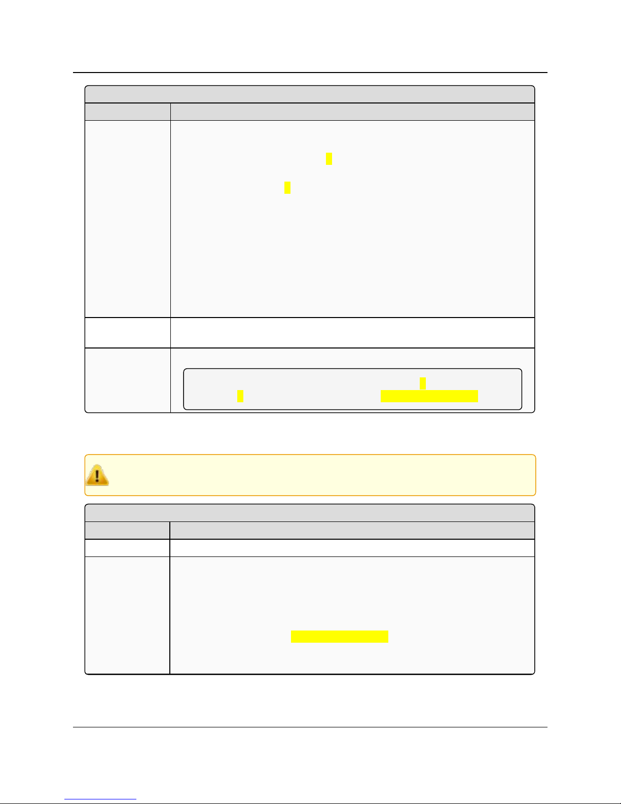
Setting Description
Options l (0) RS232 - Also used for TTL.
l (1) RS422/Full Duplex RS485 - Modbus RTU mode must be enabled and
Turn Off Delay set to at least 4.
l (2) Half Duplex RS485 - Modbus RTU mode must be enabled and Turn Off
Delay set to at least 4
l (3) DOT- DOT causes the CD line to indicate when data is transmitted on the
serial port from the radio.
l When the radio is not sending data to the serial port, CD is de-asserted.
l When the radio is sending data to the serial port, CD is asserted.
l The CD line no longer has any radio link state functionality.
l Turn Off Delay works as described in all radios.
l Turn On Delay works as described on any Slave or Slave/Repeater - it has
no functionality on the Master.
Setup Terminal
Menu
(1) Set Baud Rate > (C) RS232/485
Description Use this option to set the protocol of the data port.
Note: In TTL RF board products this setting must be 0. If set to anything
other than 0, the Setup Port must be set to Diagnostics Only.
Setup Port
Setting Description
Default Setting 3
Options l (1) MainOnly - Programming and reading a radio's setup information is done
through the data port pins only.
l (2) Diagnostics Only - Programming and reading a radio's setup information
is done through the diagnostic port only.
l If the Serial interface is set to anything other than RS232, then the Setup
Port must be set to Diagnostics Only.
l (3) Both - Programming and reading a radio's setup information is done
through either the main data port or the diagnostics port.
LRS455-C-U, -T-U, CE-U, TE-U
User & Reference Manual
2.2.6. Setup Port
Caution: Do not change this setting unless the correct programming cable is available for the
FreeWave. This document cannot be reproduced in whole or in part by any means without written permission from
new setting.
LUM0016AB Rev May-2018 Page 26 of 90 Copyright © 2018FreeWave
This document is the property of FreeWave Technologies, Inc. and contains proprietary information owned by
FreeWave Technologies, Inc.
Page 27
2. Basic Radio Programming and Setup
Setup Port
Setting Description
Setup Terminal
Menu
(1) Set Baud Rate > (D) Setup Port
Description Determines which port on the radio, Main or Diagnostics, is used to access the
parameter settings in Tool Suite or enter the Setup main menu in Setup Terminal
or a terminal emulator.
Setup mode is invoked by sending a <Shift+U> to the Diagnostics port or by
pressing/toggling the Setup button/switch, if available.
l OEM boards may also enter Setup mode when Pin 2 is grounded.
l The data port on OEMmodels uses a 2-row, 2 mm female connector.
l The diagnostic cable for this port is FreeWave Part Number: ASC2009DC.
Turn Off Delay
Setting Description
Default Setting 0
Options Any number between 0 and 9
Setup Terminal
Menu
(1) Edit Baud Rate > Turn Off Delay
Description Specifies the time after the end of transmission of a character to the RS485 bus
that the radio stops driving the bus and releases the bus to other devices.
l The units are ¼ of a character with a range of 0 to 9.
l An entry of 4 means a delay equivalent to the duration of a full character.
The default is zero delay.
l For data rates of 1200 bits/S or slower, avoid setting the Turn Off Delay
parameter higher than 4.
l At those rates the functionality of the microprocessor changes so that a
Turn Off Delay of 5 has the same effect as if set to 1, and a setting of 6
has the same effect as 2, and so on.
l Turn Off Delay must be set to a value of at least 4 for RS422 and RS485
operation.
Turn On Delay
Setting Description
Default Setting 0 ms
2.2.7. Turn Off Delay
LRS455-C-U, -T-U, CE-U, TE-U
User & Reference Manual
2.2.8. Turn On Delay
LUM0016AB Rev May-2018 Page 27 of 90 Copyright © 2018FreeWave
This document is the property of FreeWave Technologies, Inc. and contains proprietary information owned by
FreeWave. This document cannot be reproduced in whole or in part by any means without written permission from
FreeWave Technologies, Inc.
Page 28

2. Basic Radio Programming and Setup
Turn On Delay
Setting Description
Options Any number between 1 and 9
Setup Terminal
Menu
(1) Set Baud rate > (E) Turn On Delay
Description Sets the delay between when the line drivers are turned on and when the data
leaves the data port.
Use Break to Access Setup
Setting Description
Default Setting (0) Disabled
Options l (0) Disabled
l (1) Enabled - The Setup menu is set at 19200 bps.
l (2)Enabled - The setup menu is set at the radio's current baud rate.
l This setting is only available throughthe terminal interface using Setup
Terminal or another terminal emulator.
Setup Terminal
Menu
(2) Set Baud Rate > (G) Use break to access setup
Description Enables a break command to put the radio into Setup mode over the data port.
l To send a break character the end device must hold the Tx data line in the
space voltage level for longer than 1 character time.
l If a character is defined as having 1 start bit, 8 data bits, and 1 stop bit, the
character time is 10 bits, thus the Tx data line must be held in the space
voltage level for a period of time longer than 10 bits.
2.2.9. Use Break to Access Setup
Note: This setting is typically only used in OEM scenarios.
LRS455-C-U, -T-U, CE-U, TE-U
User & Reference Manual
2.3. Establishing Communication with Other Radios in the
Network
For the radios in your network to communicate successfully, you need to tell the radios what other
devices are available for them to communicate. Use one of the following options:
l Network ID - Used in MultiPoint Networks, the Network ID parameter is available in the
MultiPoint Parameters tab. Each radio in a single network should be assigned the same
network ID. A Slave links with the first Master or Repeater that it hears that has a matching
Network ID.
Because the Network ID does not use serial numbers, MultiPoint Masters and Repeaters may
be replaced without reprogramming all of the Slaves in the network. The Network ID function
LUM0016AB Rev May-2018 Page 28 of 90 Copyright © 2018FreeWave
This document is the property of FreeWave Technologies, Inc. and contains proprietary information owned by
FreeWave. This document cannot be reproduced in whole or in part by any means without written permission from
FreeWave Technologies, Inc.
Page 29

2. Basic Radio Programming and Setup
LRS455-C-U, -T-U, CE-U, TE-U
User & Reference Manual
should be used in conjunction with the Subnet ID feature (if necessary) to route data through
the radio network.
Without having the serial numbers in the Call Book, Slaves can establish communications with
different Masters that match the radio's golden settings described below, though not at the
same time. This is very useful in mobile MultiPoint applications.
For information about setting the Network ID parameter in a MultiPoint Network, see Using the
Network ID in MultiPoint Networks (on page 47).
l Call Book - The Call Book is required in Point-to-Point networks.
l The Call Book stores serial numbers of radios in the network that are allowed to talk to a
radio.
l Using the Call Book offers both security and flexibility in determining how FreeWave
radios communicate with each other.
Important!: While the Call Book is an option in Point-to-MultiPoint networks, FreeWave strongly
recommends using the Network ID feature in most applications. If a large MultiPoint network is
implemented using the Call Book and you want to add a radio to the network, or need to replace a
radio, you must physically reprogram each radio in the network and enter the new serial number in
the radio's Call Book. This can be a time consuming process and can cause a delay in getting your
network back up and running.
For more information about defining the Call Book in a Point-to-Point network, see Using the
Call Book in Point-to-Point Networks (on page 66). For more information about defining the
Call Book in a Point-to-MultiPoint network, see Using the Call Book in MultiPoint Networks (on
page 47).
2.3.1. Golden Settings
A standard network requires that the following parameters are set the same on all radios in the
network. FreeWave refers to these as the Golden Settings.
l Rx Frequency
l Tx Frequency
l Min Packet Size
l Max Packet Size
l Network ID
l RF Data Rate
Radios that contain the same settings in all these parameters can communicate with each other. If
you choose to use the Call Book instead of the Network ID, or are running a Point-to-Point
network, the appropriate serial numbers must be listed in the Call Book for each radio.
2.4. Setting RF Transmission Characteristics
The Transmission Characteristics parameters allow you to modify settings that determine how
data is sent between radios in your network. Many of these parameters must be maintained
throughout the network for proper functionality.
LUM0016AB Rev May-2018 Page 29 of 90 Copyright © 2018FreeWave
This document is the property of FreeWave Technologies, Inc. and contains proprietary information owned by
FreeWave. This document cannot be reproduced in whole or in part by any means without written permission from
FreeWave Technologies, Inc.
Page 30
2. Basic Radio Programming and Setup
Hop Table Size
Setting Description
Default Setting 16
Options Any number between 1 and 16
Setup Terminal Menu (3) Edit Radio Transmission Characteristics > (0) FreqKey > F > 2
Description Defines how many separate channels a given network uses.
LRS455-C-U, -T-U, CE-U, TE-U
User & Reference Manual
Important!: The parameters in the TransmissionCharacteristics tab are only for the advanced user
who has a good understanding of the principles of RF transmission.
Several settings on a Slave or Repeater radio come from the Master, and are therefore set only at
the Master. Settings that you must set on each Slave or Repeater include:
l Transmit Power
l Slave Security
l Retry Time Out
l Hop Table Size
You can leave most parameters in the Transmission Characteristics tab set to their default
settings when completing basic setup. However, you must set the following parameters, and they
must be the same for all radios in your network:
l Rx Frequency and Tx Frequency
l Max Packet Size
l Min Packet Size
l RF Data Rate
Set the following parameters in the Transmission Characteristics tab. These settings are available
in the Edit Radio Transmission Characteristics menu in the terminal interface, and apply to both
Point-to-Point and Point-to-MultiPoint networks, unless indicated otherwise in their description.
2.4.1. High Noise
Note: This parameter does not apply to the LRS455-C-U, -T-U, CE-U, TE-U radios.
2.4.2. Hop Table Size
Important!: This setting must be the same on all radios in the network.
Set the Hop Table Size in the Terminal Interface
1. Place the radio in Setup mode and connect to it using a terminal emulator.
2. From the main Setup menu, select (3) Transmission Characteristics > (0) Freq Key.
3. At the Enter New Frequency Key Prompt, enter F to display more options.
LUM0016AB Rev May-2018 Page 30 of 90 Copyright © 2018FreeWave
This document is the property of FreeWave Technologies, Inc. and contains proprietary information owned by
FreeWave. This document cannot be reproduced in whole or in part by any means without written permission from
FreeWave Technologies, Inc.
Page 31
2. Basic Radio Programming and Setup
Max Packet Size and Min Packet Size
Setting Description
Default Setting Max Packet Size = 8
Min Packet Size = 9
Options Any number between 0 and 9
Setup Terminal
Menu
(3) Edit TransmissionCharacteristics > (1) Max Packet Size and (2) Min Packet
Size
Description The Max Packet Size and Min Packet Size settings and the RF Data Rate
determine the number of bytes in the packets.
Note: Throughput can be enhanced when packet sizes are optimized.
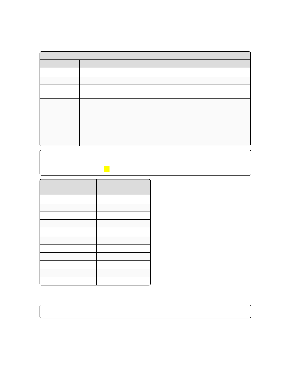
Minimum Packet Size Definition
MinSetting Min Packet Size
1 16
2 32
3 48
4 64
5 80
6 96
7 112
8 128
9 144
LRS455-C-U, -T-U, CE-U, TE-U
User & Reference Manual
4. At the prompt, enter 2 for Number of Hopping Channels.
5. At the NumChannels (1-16) prompt, enter the number of channels for the hop table and
press <Enter>.
6. Press <Esc> to return to the Radio Parameters menu.
7. Press <Esc> again to return to the main Setup menu.
2.4.3. Max Packet Size and Min Packet Size
Note: In MultiPoint networks, the Max Packet Size and Min Packet Size must be set identically in
all radios. In Point-to-Point networks the Master’s setting takes precedence over the Slave.
These tables provide the information to determine optimum setting values:
LUM0016AB Rev May-2018 Page 31 of 90 Copyright © 2018FreeWave
This document is the property of FreeWave Technologies, Inc. and contains proprietary information owned by
FreeWave. This document cannot be reproduced in whole or in part by any means without written permission from
FreeWave Technologies, Inc.
Page 32

2. Basic Radio Programming and Setup
Maximum Packet Size (2 Level FSK)
Max Setting Max Packet Size
0 32
1 48
2 64
3 80
4 96
5 112
6 128
7 135
8 135
9 135
Maximum Packet Size (4 Level FSK)
Max Setting Max Packet Size
0 32
1 48
2 64
3 80
4 96
5 112
6 128
7 144
8 160
9 176
Remote LED
Setting Description
Default Setting (0) Local Only
Options (3) Edit Radio Transmission Characteristics > (C) Remote LED
LRS455-C-U, -T-U, CE-U, TE-U
User & Reference Manual
2.4.4. Remote LED
LUM0016AB Rev May-2018 Page 32 of 90 Copyright © 2018FreeWave
This document is the property of FreeWave Technologies, Inc. and contains proprietary information owned by
FreeWave. This document cannot be reproduced in whole or in part by any means without written permission from
FreeWave Technologies, Inc.
Page 33

2. Basic Radio Programming and Setup
Remote LED
Setting Description
Setup Terminal
Menu
If using a radio with the optional 24-pin connector, use this option to connect
Remote LEDs through the diagnostics port.
When using Remote LEDs, the center (Tx) LED does not turn Green when
inSetup mode. This line is not pinned out.
l If using an enclosed radio, set the Remote LED parameter to either Remote
Only or Remote and Local.
l If you leave the setting at Local Only, you will not be able to see the LEDs.
Description l (0) Local Only - Only the LEDs on the radio board are enabled.
l (1) Remote and Local - LEDs on the radio board and remote LEDs through
the diagnostic port are enabled.
l (2) Remote Only - LEDs on the radio board are disabled. Remote LEDs
through the diagnostic port are enabled.
Retry Timeout
Setting Description
Default Setting 255
Options Any number between 0 and 255 in MultiPoint networks.
Any number between 151 and 255 in Point-to-Point networks.
Setup Terminal
Menu
(3) Edit Transmission Characteristics > (8) RetryTime Out
2.4.5. Retry Timeout
LRS455-C-U, -T-U, CE-U, TE-U
User & Reference Manual
LUM0016AB Rev May-2018 Page 33 of 90 Copyright © 2018FreeWave
This document is the property of FreeWave Technologies, Inc. and contains proprietary information owned by
FreeWave. This document cannot be reproduced in whole or in part by any means without written permission from
FreeWave Technologies, Inc.
Page 34

2. Basic Radio Programming and Setup
Retry Timeout
Setting Description
Description The Retry Time Out parameter in a Slave or Repeater sets the delay the unit
waits before dropping the connection to a Master or Repeater.
l The maximum setting means that if 1 packet in 255 is sent successfully from
the Master to the Slave or Repeater, the link is maintained.
l The minimum setting is 8.
l This allows a Slave or Repeater to drop a connection if less than 1 in 8
consecutive packets is successfully received from the Master.
l The function in the Master is effectively the same. With a setting of 255, the
Master allows a Slave or Repeater to stay connected as long as 1 packet in
255 is successfully received at the Master.
The Retry Time Out parameter is useful when a MultiPoint network has a roving
Master or Slave(s). As the link gets weaker, a lower setting allows a poor link to
break in search of a stronger one.
Setting Retry Time Out to 20 is recommended in areas where several FreeWave
networks exist. This recommended setting allows Slaves and Repeaters to drop
the connection if the link becomes too weak, while at the same time prevent errant
disconnects due to interference from neighboring networks.
While intended primarily for MultiPoint networks, the Retry Time Out parameter
may also be modified in Point-to-Point networks. However, the value in Point-toPoint mode should not be set to less than 151.
RF Data Rate
Setting Description
Default Setting (4) 12.5 kHz 4 level
Options l (4) - With an occupied bandwidth of 12.5 kHz and modulation level of 4-level
GFSK. With an RF Data Rate of 4, the maximum over-the-air operating speed
is 19,200 bps.
Important!: RF Data Rate 4 is not compatible with firmware versions 1.69
and older.
l (5) - With an occupied bandwidth of 12.5 kHz and a modulation level of 2-level
GFSK. With an RF Data Rate of 5, the maximum over-the-air operating speed
is 9600 bps.
LRS455-C-U, -T-U, CE-U, TE-U
User & Reference Manual
2.4.6. RF Data Rate
Note: In MultiPoint networks, the RF Data Rate must be identical in all radios. Any radio with an RF
Data Rate different from the Master will not establish a link. In Point-to-Point networks the Master’s
settings take precedence over the Slave.
LUM0016AB Rev May-2018 Page 34 of 90 Copyright © 2018FreeWave
This document is the property of FreeWave Technologies, Inc. and contains proprietary information owned by
FreeWave. This document cannot be reproduced in whole or in part by any means without written permission from
FreeWave Technologies, Inc.
Page 35

2. Basic Radio Programming and Setup
RF Data Rate
Setting Description
Setup Terminal
Menu
(3) Edit Transmission Characteristics > (4)RF Data Rate
Description The LRS455-C-U, -T-U, CE-U, TE-ULRS-400S radios have two settings for the
RF Data Rate (4, 5).
Important!: The RF Data Rate is the over-the-air data rate between radios
in the network, and should not be confused with the serial port baud rate.
Note: Although additional RF Data Rates are available, only rates 4 and 5
are FCC approved.
l Use setting 4 when the radios are close together and data throughput needs to
be optimized.
l Use setting 5 when the radios are farther away and a solid data link is preferred
over data throughput.
Rx Frequency
Setting Description
Default Setting 435
Options Any frequency between 435 and 470 MHz.
Note: See Frequency List (on page 82)
Setup Terminal
Menu
(3) Edit Transmission Characteristics > (0) Frequency Key > F > 0
LRS455-C-U, -T-U, CE-U, TE-U
User & Reference Manual
2.4.7. RTS to CTS
Note: This parameter does not apply to the LRS455-C-U, -T-U, CE-U, TE-U radios.
2.4.8. Rx Frequency
Note: In the Master, this setting must be the same as the Tx Frequency setting in the Slaves.
LUM0016AB Rev May-2018 Page 35 of 90 Copyright © 2018FreeWave
This document is the property of FreeWave Technologies, Inc. and contains proprietary information owned by
FreeWave. This document cannot be reproduced in whole or in part by any means without written permission from
FreeWave Technologies, Inc.
Page 36

2. Basic Radio Programming and Setup
Rx Frequency
Setting Description
Description The radios must be programmed to operate on the appropriate frequency.
To program the radio for single-channel operation, enter the frequency, in
Megahertz, in the Tx Frequency and Rx Frequency fields. By default, the radio is
set for single-channel operation.
If the radios are to operate in Frequency Division Duplex, the Tx Frequency and
Rx Frequency fields have different frequencies assigned.
Define the Tx Frequency and Rx Frequency for multiple channels through the
terminal interface using Setup Terminal or another terminal emulator.
LRS455-C-U, -T-U, CE-U, TE-U
User & Reference Manual
Set the Radio to a Single Channel in a Terminal Emulator
1. Place the radio in Setup Mode and connect to it in Setup Terminal or a terminal emulator.
2. On the main Setup menu, select (3) Edit Transmission Characteristics > (0) FreqKey.
3. At the Enter New Frequency Key Prompt, enter F to view more options.
The 16 channels and their transmit and receive frequencies appear.
4. At the prompt, enter 1 for Single Frequency.
5. At the Enter Frequency Channel to Use prompt, enter the frequency channel to use
between
0 and 15 and press <Enter>.
The entered number corresponds with the channel number as listed in the channel table.
6. Press <Esc> to return to the Radio Parameters menu.
7. Press <Esc> again to return to the main Setup menu.
Set the Radio to Hop Channels
1. Place the radio in Setup Mode and connect to it in Setup Terminal or a terminal emulator.
2. From the main Setup menu, select (3) Edit Transmission Characteristics > (0)
FreqKey.
3. At the Enter New Frequency Key Prompt, enter 0.
4. Press <Esc> to return to the Radio Parameters menu.
5. Press <Esc> again to return to the main Setup menu.
Edit Frequencies for Multiple Channels
Important!: The regulating body in the country where you are using the LRS455-C-U, -T-U, CE-U,
TE-U radio determines if you can run the radio in multichannel mode.
1. Place the radio in Setup Mode and connect to it in Setup Terminal or a terminal emulator.
2. From the main Setup menu, select (3) Edit Transmission Characteristics > (0)
FreqKey.
3. At the Enter New Frequency Key Prompt, enter F to display more options.
LUM0016AB Rev May-2018 Page 36 of 90 Copyright © 2018FreeWave
This document is the property of FreeWave Technologies, Inc. and contains proprietary information owned by
FreeWave. This document cannot be reproduced in whole or in part by any means without written permission from
FreeWave Technologies, Inc.
Page 37

2. Basic Radio Programming and Setup
Slave Security
Setting Description
Default Setting (0) On
Options (0) On, (1) Off
Setup Terminal
Menu
(3) Edit TransmissionCharacteristics > (6) Slave Security
Description Slave Security allows Slave radios to accept transmissions from a Master not
included in the Call Book. The default setting of 0 (On), means only Masters in
the Slaves’ Call Book may link to that Slave.
l Slave Security may be disabled (setting of 1) allowing any Master to call the
Slave.
l Slave Security must be set to 1 when the unit is operating in Mode 6
Slave/Master Switchable or a Point-to-Point network where the Slave may
need to accept calls from more than 10 different Masters.
l When Slave Security is set to 1, the radio accepts calls from any other
FreeWave radio.
l Additional network security measures may be taken to prevent unauthorized
access, such as changing default settings for Frequency and Hop Table.
LRS455-C-U, -T-U, CE-U, TE-U
User & Reference Manual
The 16 channels and their transmit and receive frequencies display.
4. At the prompt, enter 0 for to edit the hop table.
5. At the Channel Number (0-15) prompt, enter the channel number you want to change and
press <Enter>.
6. At the Xmit Chan (0-5600) prompt, enter a transmit channel number between 0 and 5600
and press <Enter>.
7. At the Rcv Chan (0-5600) prompt, enter a transmit channel number between 0 and 5600
and press <Enter>.
The channel table updates to reflect the changes.
8. Press <Esc> to return to the Radio Parameters menu.
9. Press <Esc> again to return to the main Setup menu.
2.4.9. Slave Security
Important!: Slave Security has no effect in Point-to-MultiPoint networks where the Network ID is
used instead of the Call Book.
LUM0016AB Rev May-2018 Page 37 of 90 Copyright © 2018FreeWave
This document is the property of FreeWave Technologies, Inc. and contains proprietary information owned by
FreeWave. This document cannot be reproduced in whole or in part by any means without written permission from
FreeWave Technologies, Inc.
Page 38
2. Basic Radio Programming and Setup
Transmit Power
Setting Description
Default Setting 10
Options Any number between 0 and 10
Setup Terminal
Menu
(3)Edit Transmission Characteristics > (5) RF Xmit Power
Description Sets the output power of the radio. You can control the output transmit power up to
2 W (+33 dBm).
For use in applications requiring greater than 70% transmit duty cycle, the radios
must be attached to an appropriate heat sink.
When testing radios at your facility and they are in close proximity to one another,
set the Transmit Power parameter to a low number. When you deploy radios to
the field, raise the Transmit Power number accordingly.
Transmit
Power Setting
RF Transmit
Power (dBm)
10 +33
9 +32
8 +31
7 +30
6 +29
5 +28
4 +27
3 +26
2 +25
1 +24
0 +23
2.4.10. Transmit Power
Important!: This table is for reference only.
All Transmit Power settings below 9 are approximate.
A Transmit Power setting of 10 is +33 dBm.
LRS455-C-U, -T-U, CE-U, TE-U
User & Reference Manual
2.4.11. Transmit Rate
Important!: This setting must be the same on radios in the network.
LUM0016AB Rev May-2018 Page 38 of 90 Copyright © 2018FreeWave
This document is the property of FreeWave Technologies, Inc. and contains proprietary information owned by
FreeWave. This document cannot be reproduced in whole or in part by any means without written permission from
FreeWave Technologies, Inc.
Page 39

2. Basic Radio Programming and Setup
Transmit Rate
Setting Description
Default Setting (1) Normal
Options Any number between 0 to 9
Setup Terminal
Menu
(3) Edit TransmissionCharacteristics > (3) Xmit Rate
Description FreeWave radios use a Master Transmit Beacon to provide low current
consumption in the Slave radios.
l The Slaves turn their receiver off when no data is being passed.
l This setting allows the duty cycle of the Master Transmit Beacon to be
changed.
l A setting of 0 is the highest duty cycle and 9 is the lowest duty cycle.
If not frequently polling for data or installing new devices, lower the
duty cycle (i.e., set this field to 9).
Tx Frequency
Setting Description
Default Setting 435
Options Any frequency between 435 and 470 MHz.
Note: See Frequency List (on page 82) for more information.
Setup Terminal
Menu
(3) Edit Transmission Characteristics > (0) FreqKey
Description The radios must be programmed to operate on the appropriate frequency. To
program the radio for single channel operation, enter the frequency, in Megahertz,
into the Tx Frequency and Rx Frequency fields.
If the radios are to operate in Frequency Division Duplex, the Tx Frequency and
Rx Frequency fields have different frequencies assigned.
The Tx Frequency field in the Tool Suite Configuration application handles only a
single channel. To set multiple channels, use the terminal interface. For
information, see the instructions in Rx Frequency (on page 35).
LRS455-C-U, -T-U, CE-U, TE-U
User & Reference Manual
2.4.12. Tx Frequency
Important!: In the Master, this setting must be the same as the Rx Frequency setting in the Slaves.
LUM0016AB Rev May-2018 Page 39 of 90 Copyright © 2018FreeWave
This document is the property of FreeWave Technologies, Inc. and contains proprietary information owned by
FreeWave. This document cannot be reproduced in whole or in part by any means without written permission from
FreeWave Technologies, Inc.
Page 40

2. Basic Radio Programming and Setup
LRS455-C-U, -T-U, CE-U, TE-U
User & Reference Manual
2.5. Setting Radio Passwords
Use passwords to prevent access to or changing of any of the radio’s parameters. This option is
useful if you want to prevent unauthorized personnel from gaining access to the radio settings.
If the Setup Port option in the Baud Rate tab is set to (1) Main Only or (3) Both, the
password is only accepted if the option is accessed from the main data port. To use the Password
function using the diagnostics port, the Setup Port option must be set to (2) Diagnostics
Only.
Warning! If the password feature is enabled and the password is forgotten, you need to return
the radio to FreeWave to have the password disabled.
2.5.1. Set a Password
1. From the Setup main menu in the terminal interface, select (8) Chg Password to show
this prompt: New PW? (<esc> to exit).
2. To back out of the process and not enable the password press <Esc>.
To set a password, type exactly four characters.
Passwords are case sensitive.
Note: Press <Esc> to cancel the process at any point.
After the four characters are entered, this prompt appears: <Enter> to accept,<esc> to
quit.
3. To accept the password as entered and enable the feature, press <Enter>.
To quit the process and not enable the password, press <Esc>.
If you press <Enter>, the password appears on the line above.
Important!: The password is case sensitive and every keystroke is a character.
2.5.2. Change the Password
1. On the Setup main menu in the terminal interface, select (8) Chg Password.
2. At the Enter Security Code prompt enter the current four character, case sensitive
password.
After entering the password correctly, the prompt to enter the new password appears.
3. Enter the new four character, case sensitive password.
4. To accept the password as entered and enable the feature, press <Enter>.
To quit the process and not enable the password, press <Esc>.
If you press <Enter>, the password appears on the line above.
Important!: The password is case sensitive and every keystroke is a character.
LUM0016AB Rev May-2018 Page 40 of 90 Copyright © 2018FreeWave
This document is the property of FreeWave Technologies, Inc. and contains proprietary information owned by
FreeWave. This document cannot be reproduced in whole or in part by any means without written permission from
FreeWave Technologies, Inc.
Page 41

2. Basic Radio Programming and Setup
LRS455-C-U, -T-U, CE-U, TE-U
User & Reference Manual
2.5.3. Disable the Password
The password can be disables if the current password is known.
Important!: You can only disable a password using the prompt when you read the radio in Tool Suite,
or through a terminal emulator. You cannot disable the password using Setup Terminal application in
Tool Suite.
1. From the Setup main menu in the terminal interface, select (8) Chg Password.
2. Hold down the <Alt> key and type 0255 using the number pad on the keyboard and
release the <Alt> key.
3. Repeat this step three more times (hold the <Alt> key and type 0255 a total of 4 times).
Important!: You must type the 0255 using the NUM Pad on your computer, NOT the top row
of numerals.
After the fourth entry, the password is disabled.
LUM0016AB Rev May-2018 Page 41 of 90 Copyright © 2018FreeWave
This document is the property of FreeWave Technologies, Inc. and contains proprietary information owned by
FreeWave. This document cannot be reproduced in whole or in part by any means without written permission from
FreeWave Technologies, Inc.
Page 42

LRS455-C-U, -T-U, CE-U, TE-U
User & Reference Manual
3. Configuring Point-to-MultiPoint Networks
When installing MultiPoint networks it is important to do some up front planning around the
devices you are going to implement and the route your data is going to take back to the Master. A
MultiPoint network can contain the following devices:
l Only one Master. All communications are from and to the Master.
l An unlimited number of Slaves (remote sites).
l An LRS455-C-U, -T-U, CE-U, TE-U MultiPoint network can have only one Repeater.
l A Serial Repeater can be a Slave and a Repeater at the same time.
This chapter builds on the settings described in the previous chapters and provides details about
the following setup that applies specifically to a MultiPoint network:
l Point-to-MultiPoint network characteristics.
l Using the Network ID or the Call Book to establish which radios in the network can
communicate with each other.
l Using subnet IDs to route communication through the network, back to the Master.
l Settings and recommendations for additional parameters that apply to a MultiPoint
network.
l Conserving power in devices within the network.
l Running network diagnostics.
LUM0016AB Rev May-2018 Page 42 of 90 Copyright © 2018FreeWave
This document is the property of FreeWave Technologies, Inc. and contains proprietary information owned by
FreeWave. This document cannot be reproduced in whole or in part by any means without written permission from
FreeWave Technologies, Inc.
Page 43

3. Configuring Point-to-MultiPoint Networks
LRS455-C-U, -T-U, CE-U, TE-U
User & Reference Manual
3.1. Point-to-MultiPoint Network Quick Start
This is a quick start guide for setting up two radios in Point-to-MultiPoint mode. This mode allows
for a Master to communicate with several Slaves simultaneously.
3.1.1. Point-to-MultiPoint Network Quick Start (Tool Suite)
1. Connect the radio to the serial port of a computer either through a serial cable or using the
diagnostics cable.
2. Connect the radio to a power source (+6.0 to +27.0 VDC).
Warning! Do not connect the LRS455-C-U, -T-U, CE-U, TE-U series radios to DC
power without terminating the antenna port to a suitable load, such as a 50 ohm antenna,
or an attenuator with a power rating greater than or equal to 2 W. Powering up without a
load attached will damage the radio and void the warranty.
3. Open a Tool Suite session, select the Configuration application, and ensure the correct
port is selected in the Com Port field in the upper left of the Configuration ribbon.
4. From the Networks section of the Configuration ribbon, select the network in which the
radio resides or click Add Network to create a new network in Tool Suite.
5. Click Read Radio in the Configuration ribbon to read the radio's current settings.
l If using a diagnostics cable to connect to the radio, the radio automatically goes into
Setup mode.
l If using a data cable to connect to the radio, you are prompted to press the radio's
Setup button to put the radio in Setup mode. If you are using a board-level radio, use
the interrupt line to short pin 2 and 4.
l When in Setup mode, all three LEDs on the radio display solid green ( ).
6. Click the Operation Mode tab.
7. In the Modem Mode field, select 2 to set the radio as a Point-to-MultiPoint Master or select
3 to set the radio as a Point-to-MultiPoint Slave.
Important!: A network can have only one Master.
8. Click the Baud Rate tab.
9. Change the Baud Rate, Data Parity, and Modbus RTU to match the device that the radio
is to be attached to.
10. Click the Transmission Characteristics tab.
11. Set these parameters so they are identical on all radios in the network:
l Tx Frequency
l Rx Frequency
l Max Packet Size
l Min Packet Size
l RF Data Rate (Only 4 and 5 are approved by the FCC for use in the UnitedStates).
LUM0016AB Rev May-2018 Page 43 of 90 Copyright © 2018FreeWave
This document is the property of FreeWave Technologies, Inc. and contains proprietary information owned by
FreeWave. This document cannot be reproduced in whole or in part by any means without written permission from
FreeWave Technologies, Inc.
Page 44

3. Configuring Point-to-MultiPoint Networks
LRS455-C-U, -T-U, CE-U, TE-U
User & Reference Manual
Note: Changing these settings from the factory defaults may help to eliminate interference
from other FreeWave networks.
12. Click the MultiPoint Parameters tab.
13. In the Network ID field, set the value to any value between 1 and 4095, except 255.
FREEWAVE Recommends: FreeWave recommends setting the Network ID to the last
three or four digits of the Master radio's serial number, as this is a number you can look up if
necessary.
Important!: This value must be the same in all radios in the network.
3.1.2. Point-to-MultiPoint Network Quick Start (Terminal Interface)
1. Connect the radio to the serial port of a computer either through a serial cable or using the
diagnostics cable.
2. Connect the radio to a power source (+6.0 to +27.0 VDC).
Warning! Do not connect the LRS455-C-U, -T-U, CE-U, TE-U series radios to DC
power without terminating the antenna port to a suitable load, such as a 50 ohm antenna,
or an attenuator with a power rating greater than or equal to 2 W. Powering up without a
load attached will damage the radio and void the warranty.
3. Open a terminal emulator session.
4. Connect to COMx (where 'x' is the number of the Com port being connected).
5. Define these settings as:
l Data Rate = 19,200
l Data Bits = 8
l Parity = None
l Stop Bits = 1
l Flow Control = None
6. If you are using the data cable, press the Setup button on the radio or use the interrupt line
to short pin 2 and 4.
If using the diagnostics cable, press <Shift+U>.
l When in Setup mode, all three LEDs on the radio display solid green ( ).
l The Main menu appears on the screen.
7. Press 0 to open the Operation Mode menu.
8. Press 2 to set the radio as a Point-to-MultiPoint Master or press 3 to set the radio as a
Point-to-MultiPoint Slave.
9. Press <Esc> to return to the Main menu.
LUM0016AB Rev May-2018 Page 44 of 90 Copyright © 2018FreeWave
This document is the property of FreeWave Technologies, Inc. and contains proprietary information owned by
FreeWave. This document cannot be reproduced in whole or in part by any means without written permission from
FreeWave Technologies, Inc.
Page 45

3. Configuring Point-to-MultiPoint Networks
LRS455-C-U, -T-U, CE-U, TE-U
User & Reference Manual
Important!: A network can have only one Master.
10. Press 1 in the Main menu.
11. Change the Baud Rate, Data Parity, and Modbus RTU to match the device that the radio
is to be attached to.
12. Press <Esc> to return to the Main menu.
13. Press 3 in the Main menu.
14. Set these parameters so they are identical on all radios in the network:
l Tx Frequency
l Rx Frequency
l Max Packet Size
l Min Packet Size
l RF Data Rate (Only 4 and 5 are approved by the FCC for use in the United States).
Note: The Tx Frequency and Rx Frequency options, or Frequency Key, are located in the F
submenu after you press 0 to access the Frequency Key menu in Main menu 3.
Note: Changing these settings from the factory defaults may help to eliminate interference
from other FreeWave networks.
15. Press <Esc> to return to the Main menu.
16. Press 5 in the Main menu.
17. In the Network ID field, set the value to any value between 1 and 4095, except 255.
FREEWAVE Recommends: FreeWave recommends setting the Network ID to the last
three or four digits of the Master radio's serial number, as this is a number you can look up if
necessary.
Important!: This value must be the same in all radios in the network.
18. Press <Esc> to exit the Setup menu and resume normal radio operation.
LUM0016AB Rev May-2018 Page 45 of 90 Copyright © 2018FreeWave
This document is the property of FreeWave Technologies, Inc. and contains proprietary information owned by
FreeWave. This document cannot be reproduced in whole or in part by any means without written permission from
FreeWave Technologies, Inc.
Page 46
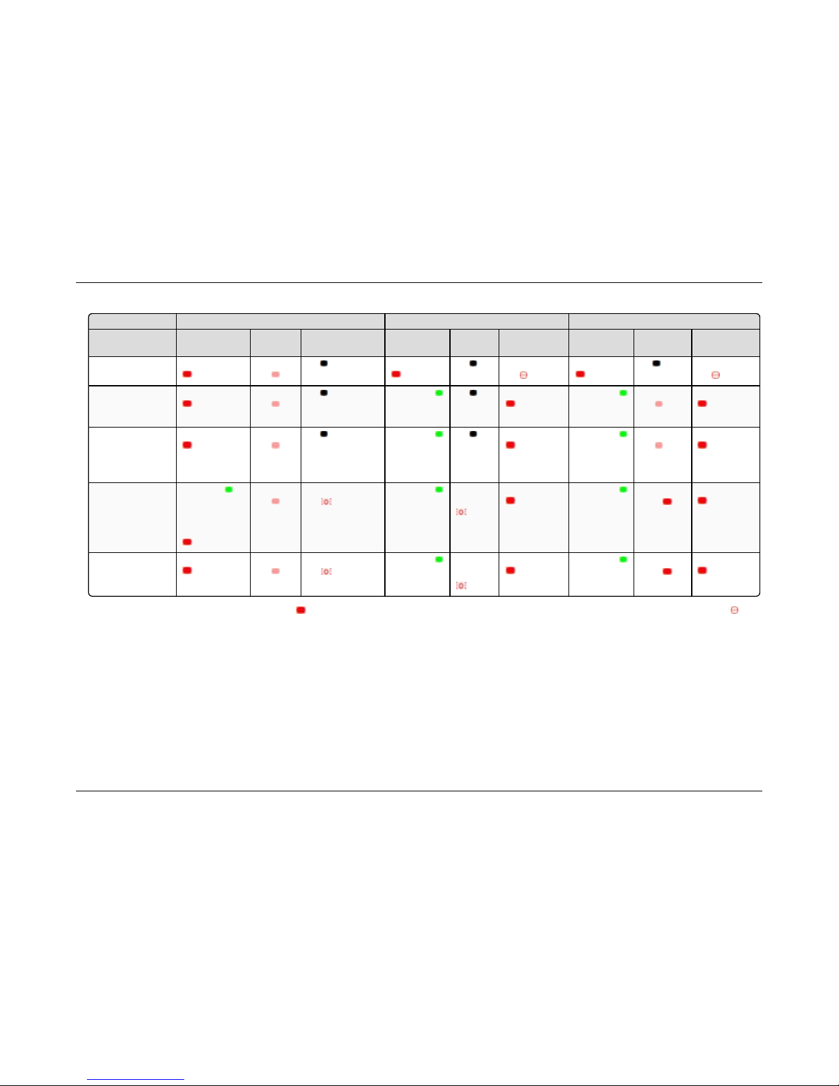
3.2. Point-to-MultiPoint Operation LEDs
Master Slave Repeat er
Con dition
Carrier Detect
(CD)
Transmit
(Tx)
Clear to Send
(CTS)
Carrier Detect
(CD)
Transmit
(Tx)
Clear to Send
(CTS)
Carrier Detect
(CD)
Transmit (Tx)
Clear to Send
(CTS)
Powered, not linked Solid red bright Solid red
dim
Off
Solid red bright
Off
Blinking
red
Solid red bright
Off
Blinking
red
Repeater and Slave
linkedto Master , no
data
Solid red bright Solid red
dim
Off Solid green Off
Solid red bright
Solid green
Solid red
dim
Solid red bright
Repeater and Slave
linkedto Master ,
Master
sending data to Slave.
Solid red bright Solid red
dim
Off Solid green Off
Solid red bright
Solid green
Solid red
dim
Solid red bright
Repeater and Slave
linkedto Master ,
Slave
sending data to
Master.
Solid green
RCV data
or
Solid red bright
Solid red
dim
Intermittent flashing
red
Solid green
Intermittent
flash red
Solid red bright
Solid green
Solid red
bright
Solid red bright
Master with
diagnosticsprogram
running
Solid red bright Solid red
dim
Intermittent flashing
red
Solid green
Intermittent
flash red
Solid red bright
Solid green
Solid red
bright
Solid red bright
* In an idle condition, the CTS LED is solid red with a solid link, as the link weakens the CTS LED on the Repeater andSlave begins to blink .
LUM0016AB R ev May-2018 Page 46 of 90 Copyright © 201 8FreeWave
This document is the p roperty of FreeWave Technologies, Inc. and contains proprietary information o wned by FreeWave. This document cannot be reprod uced
in whole or in pa rt by any means wi thout written permission from FreeWave Techn ologies, Inc.
3. Configuring Point-to-MultiPoint Networks LRS455-C-U, -T-U, CE-U, TE-U User & Reference Manual
Page 47

3. Configuring Point-to-MultiPoint Networks
LRS455-C-U, -T-U, CE-U, TE-U
User & Reference Manual
3.3. Overlapping MultiPoint Networks
Overlapping MultiPoint networks may be set up effectively with FreeWave radios when several
key parameters are set correctly. Overlapping MultiPoint networks are defined as networks using
different Master, which share or overlap in a specific geographic area.
Co-located MultiPoint networks require the following parameters be unique for each network:
l Network ID, unless using the Call Book
l Max Packet Size
l Min Packet Size
Note: For more information about the installation of Point-to-MultiPoint networks, contact FreeWave
Technical Support.
3.4. Establishing Communication with Other Radios in a
MultiPoint Network
For the radios in the network to communicate successfully, tell the radio what other devices are
available for them to communicate with. You can use the Network ID or the Call Book.
FREEWAVE Recommends: Use the Network ID option instead of the Call Book in MultiPoint
networks. Because the Network ID does not use serial numbers, MultiPoint Master and Repeaters
may be added or replaced without reprogramming all of the Slave in the network.
3.4.1. Using the Network ID in MultiPoint Networks
The Network ID parameter is located in the MultiPoint Parameters tab. A radio from the factory
has a Network ID setting of 255, which enables the Call Book. Assign each radio in a single
network the same Network ID. The Slave links with the first Master or Repeater it hears that has
a matching Network ID.
Keep the following in mind when setting the Network ID:
l The value can be any value between 0 and 4095, NOT 255.
l To help ensure your ID is unique to your network, avoid using numbers that coincide with
nearby landmarks or highways.
l FreeWave recommends a Network IDof four characters.
l For example, the last four digits of the Master's serial number, which is ensured to be
unique and does not overlap with other nearby FreeWave networks.
l Use the Network ID function in conjunction with the Subnet ID feature (if necessary) to
route data through the radio network.
3.4.2. Using the Call Book in MultiPoint Networks
Although not recommended, the Call Book is an option in MultiPoint networks. If the Network ID
feature is used in a MultiPoint network, no entries are needed in the Call Book of any of the radios.
LUM0016AB Rev May-2018 Page 47 of 90 Copyright © 2018FreeWave
This document is the property of FreeWave Technologies, Inc. and contains proprietary information owned by
FreeWave. This document cannot be reproduced in whole or in part by any means without written permission from
FreeWave Technologies, Inc.
Page 48

3. Configuring Point-to-MultiPoint Networks
FREEWAVE Recommends: Use the Network ID feature in a MultiPoint network. Using the Call
Book in a MultiPoint network can cause delay in resuming communication if a Master is damaged.
Note: For information about setting the Call Book, see Using the Call Book in Point-to-Point
Networks (on page 66).
LRS455-C-U, -T-U, CE-U, TE-U
User & Reference Manual
In a MultiPoint network, the Slaves and Repeater are not listed in the Master's Call Book. A Slave
must have the Master and the Repeater it is going to use in its Call Book.
These examples show the Call Books of a MultiPoint network comprised of a Master, Repeater,
and Slave in which the Slave can communicate either through the Repeater or directly to the
Master:
MultiPoint Master Call Book (Unit Serial Number 900-0001)
Entry Number Repeater 1
(0) 000-0000
(1) 000-0000
No serial number entries are necessary in the Master’s Call Book.
MultiPoint Repeater Call Book (Unit Serial Number 900-0002)
Entry Number Repeater 1
(0) 900-0001
(1) 000-0000
MultiPoint Slave Call Book (Unit Serial Number 900-0003)
Entry Number Repeater 1
(0) 900-0001
(1) 900-0002
(2) 000-0000
At times, you may want to force a Slave to go through a specific MultiPoint Repeater. In this
scenario, the Slave’s Call Book should contain only the serial number for that Repeater as the
entry on line 0.
3.5. Routing Communication Through the Network
When using the Network ID feature, a Repeater or Slave links to the first Repeater or Master is
hears with the same ID. Using subnet IDs, you can determine the path a Repeater or Slave uses
to communicate back to the Master.
By forcing the communication path, you can optimize performance of the network by ensuring the
Repeater or Slave links to a Repeater or Master with robust RF communications. Subnet IDs can
help to minimize latency. By designing paths in a network, you can create the most efficient
communication paths.
LUM0016AB Rev May-2018 Page 48 of 90 Copyright © 2018FreeWave
This document is the property of FreeWave Technologies, Inc. and contains proprietary information owned by
FreeWave. This document cannot be reproduced in whole or in part by any means without written permission from
FreeWave Technologies, Inc.
Page 49

3. Configuring Point-to-MultiPoint Networks
LRS455-C-U, -T-U, CE-U, TE-U
User & Reference Manual
3.5.1. Assigning Subnet ID Values
Subnet IDs consist of two parts, both available in the Multipoint Parameters tab:
l Rx - This setting identifies which radio a Repeater or Slave listens to. In the terminal
interface, this is the Rcv Subnet ID.
l Tx - This setting identifies the ID on which this device transmits, and in turn which devices
listen to it. The Tx Subnet ID parameter is relevant for Multipoint Master radios and
Repeaters only. In the terminal interface, this is the Xmt Subnet ID.
The default (disable) setting for both Rx and Tx is F, which is a visual way to indicate that the
device is the final in the line of communication and does not use a subnet ID. A Multipoint Slave
with a Subnet ID of F,F does not roam from one Repeater or network to the next, it only links to a
Master or Repeater that has either a Tx setting of 0 or an F,F Subnet ID.
Setting both Rx and Tx Subnet ID to 0 allows a mobile Slave to roam from subnet to subnet, and
possibly from network to network, provided the Network ID, Max and Min Packet Size, and RF
Data Rates are the same between networks.
The examples in this section show the subnet definitions from the Master radio through the
network to the Slave radios. When the subnet path is defined, the Slave radios can follow the
route back to the Master.
In the following example, the Repeater and Slave 1 must talk directly to the Master. Slave 2 and
Slave 3 must talk directly to the Repeater. Slave 4 may link to the Master or Repeater, whichever it
hears first in the network.
Figure 11: Repeater and Slave 1 Must Talk Directly to the Master
LUM0016AB Rev May-2018 Page 49 of 90 Copyright © 2018FreeWave
This document is the property of FreeWave Technologies, Inc. and contains proprietary information owned by
FreeWave. This document cannot be reproduced in whole or in part by any means without written permission from
FreeWave Technologies, Inc.
Page 50

3. Configuring Point-to-MultiPoint Networks
Radio Rx Tx Description
Master 0 0 The default settings (F, F) actually use 0, 0. The Rx Subnet on the Master has
no effect on the network.
Slave 1 0 F Rx Subnet = 0 forces the radio to link only to the Master. The Slave does not
transmit to any device except the Master, so its Tx Subnet is F.
Repeater 0 1 Rx Subnet = 0 forces the radio to link only to the Master. Transmits on subnet
1.
Slave 2 1 F Rx Subnet = 1 forces the radio to link only the Repeater.
Slave 3 1 F Rx Subnet = 1 forces the radio to link only to the Repeater.
Slave 4 0 0 The 0,0 setting allows the Slave to link with the Master or Repeater with the
same Network ID, whichever it hears first.
1 PPS Enable Delay
Setting Description
Default Setting 255
Options 255 to disable 1 PPS
0 to 254 to enter the delay
Setup Terminal
Menu
(5) Edit MultiPoint Parameters > (9) 1 PPS Enable/Delay
Description The 1 PPS Enable/Delay setting allows the radio network to propagate a 1PPS
signal from the Master to all Slaves in a MultiPoint network.
When this parameter is enabled a properly generated pulse applied on the DTR
line of the Master provides a 1 PPS pulse on the CD line of any Slave in the
network
LRS455-C-U, -T-U, CE-U, TE-U
User & Reference Manual
Subnet ID Settings for This Example
3.6. Setting Other MultiPoint Parameters
The other MultiPoint Parameters options allow you to modify several different parameters in the
radio that determine the characteristics of a MultiPoint network.
Set the following parameters in the MultiPoint Parameters tab. These settings are available in
the MultiPoint Parameters menu in the terminal interface.
3.6.1. 1 PPS Enable Delay
Setup 1PPS Enable/Delay
1. Set the 1 PPS Enable/Delay parameter to 0 in the Master.
The Master must have a 1 PPS pulse on the DTR pin.
2. Enable the 1 PPS Enable/Delay parameter on the Slaves.
Slaves are calibrated at the factory.
LUM0016AB Rev May-2018 Page 50 of 90 Copyright © 2018FreeWave
This document is the property of FreeWave Technologies, Inc. and contains proprietary information owned by
FreeWave. This document cannot be reproduced in whole or in part by any means without written permission from
FreeWave Technologies, Inc.
Page 51

3. Configuring Point-to-MultiPoint Networks
Diagnostics
Setting Description
Default Setting 1
Options Any number between 0 and 128
Setup Terminal
Menu
(5) Edit MultiPoint Parameters > (B) Diagnostics
LRS455-C-U, -T-U, CE-U, TE-U
User & Reference Manual
Calibrate a Slave in 1PPS Enable/Delay Mode
1. Trigger an oscilloscope on the 1 PPS pulse on the DTR line of the Master.
2. Monitor the CD line of the Slave.
3. If the timing on the Slave differs from the Master it may be adjusted via the value in the
Slave's 1 PPS Enable/Delay parameter. The difference in time between each incremental
integer value is 542.534 nS. Changing the parameter to higher values decreases the Slave
time delay and changing the parameter to lower values increases the time delay.
When properly calibrated the CD line of a Slave radio outputs a pulse that goes high for about 2
ms in synch with the 1 PPS pulse on the Master radio. The output on the Slave occurs within 20
microseconds of the input to the Master.
Important!: When 1 PPS Enable/Delay is enabled, the Master must have a 1 PPS pulse on its
DTR pin, otherwise the RF network does not function.
3.6.2. Diagnostics
LUM0016AB Rev May-2018 Page 51 of 90 Copyright © 2018FreeWave
This document is the property of FreeWave Technologies, Inc. and contains proprietary information owned by
FreeWave. This document cannot be reproduced in whole or in part by any means without written permission from
FreeWave Technologies, Inc.
Page 52

3. Configuring Point-to-MultiPoint Networks
Diagnostics
Setting Description
Description Allows diagnostics data in the Network Diagnostics application within Tool Suite
to be viewed at the Master in parallel with application data. The setting in this
parameter determines how many slots out of 128 are dedicated to diagnostics.
Example: If you set to 10, 1 out of every 10 data slots is for diagnostics
data; if you set to 100, 1 out of every 100 data slots is for diagnostics data.
Diagnostics is always secondary to actual transmitted data.
The diagnostic program must be run from the Master radio. Diagnostics requires
the following:
l A setting of this parameter on the Master between 1 and 128.
l A second computer or serial connection to run the diagnostics software.
l A diagnostics cable. (Available from FreeWave.)
l Diagnostics software.
FREEWAVE Recommends: When collecting diagnostics from an
LRS455-C-U, -T-U, CE-U, TE-U network, FreeWave recommends setting
the diagnostics polling rate to 400 ms or higher.
Note: For more information about Diagnostics, contact FreeWave
Technical Support.
Master Packet Repeat
Setting Description
Default Setting 2
Options Any number between 0 and 9
Setup Terminal
Menu
(5) Edit Multipoint Parameters > (1) Master Packet Repeat
LRS455-C-U, -T-U, CE-U, TE-U
User & Reference Manual
3.6.3. DTR Connect
Note: This parameter does not apply to the LRS455-C-U, -T-U, CE-U, TE-U radios.
3.6.4. Local Mode
Note: This parameter does not apply to the LRS455-C-U, -T-U, CE-U, TE-U radios.
3.6.5. Master Packet Repeat
LUM0016AB Rev May-2018 Page 52 of 90 Copyright © 2018FreeWave
This document is the property of FreeWave Technologies, Inc. and contains proprietary information owned by
FreeWave. This document cannot be reproduced in whole or in part by any means without written permission from
FreeWave Technologies, Inc.
Page 53
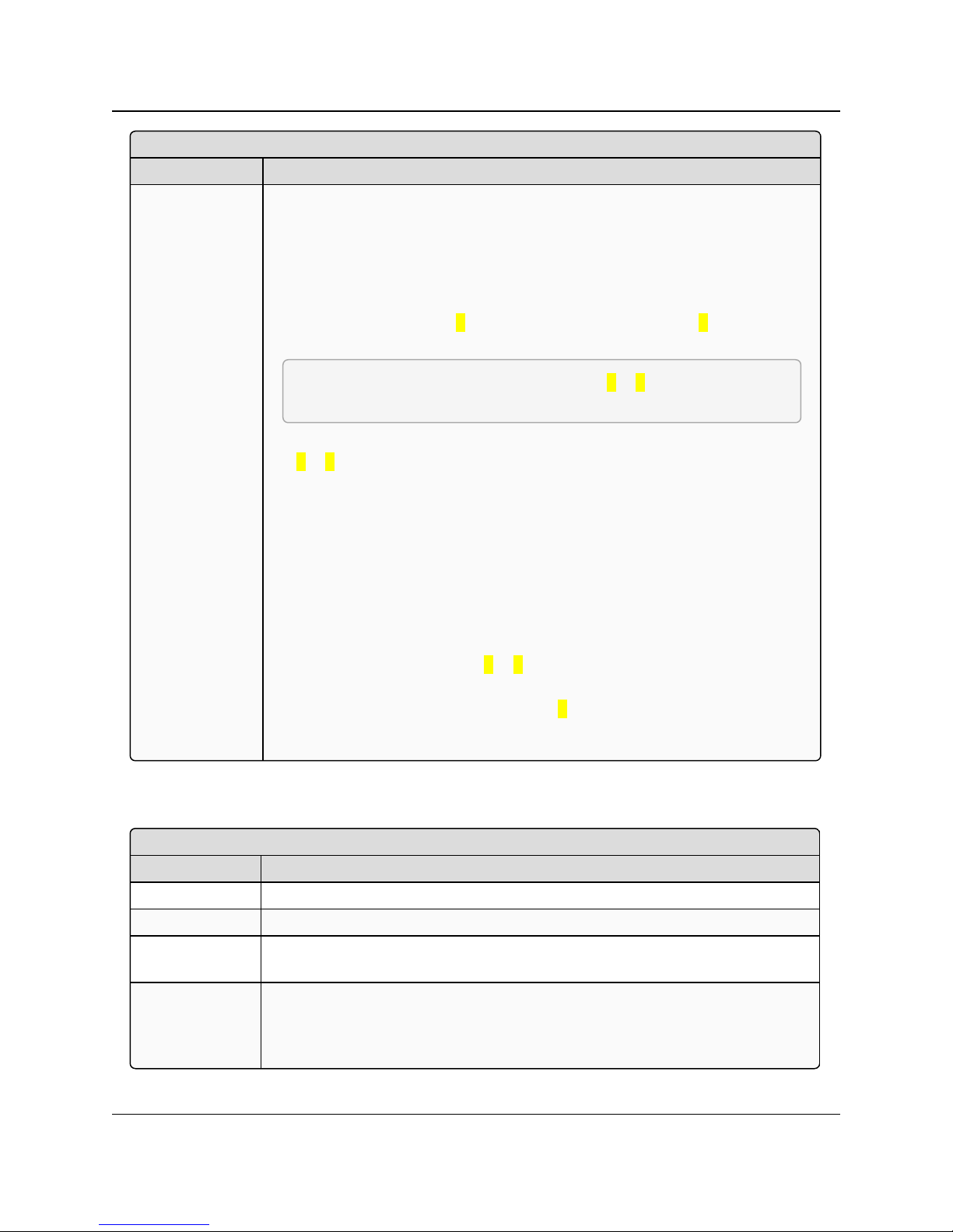
3. Configuring Point-to-MultiPoint Networks
Master Packet Repeat
Setting Description
Description In a Point-to-MultiPoint network, Slaves do not acknowledge transmissions from
the Master. If Slaves did acknowledge all data transmissions, in a large network,
the Master would soon become overwhelmed with acknowledgments from the
Slaves. Without acknowledgments, 100% confidence every Slave has received
every packet cannot be met.
To address this issue, you can modify the Master Packet Repeat parameter,
assigning a value between 0 (the packet is transmitted once) to 9 (the packet is
transmitted 10 times).
FREEWAVE Recommends: Use a setting of 1 or 2 in a licensed
network.
For networks with solid RF links, this parameter should be set to a low value such
as 0 or 1. If a network has some weak or marginal links it should be set with
higher values. If a Slave receives a good packet from a Master more than once it
discards the repeated packets. Similarly, after a MultiPoint Repeater receives a
good packet from the Master, it discards any further repeated packets. In turn, the
Repeater sends the packet out to Slaves the number of times corresponding to its
own Master Packet Repeat setting.
Increasing the Master Packet Repeat setting increases the probability of a
packet getting through, but also increases latency in the network because each
packet from the Master or Repeater is being sent multiple times. Therefore, it is
important to find the optimal mix between network robustness, throughput, and
latency. In general, a setting of 0 to 1 works well for most well designed
networks.
The Master Packet Repeat may be set to 0 if the user software is capable of, or
requires acknowledgment. In this case, if the Master sends a packet that the
Slave does not receive, the user software controls the retries as needed.
Max Slave Retry
Setting Description
Default Setting 9
Options Any number between 0 and 9
Setup Terminal
Menu
(5) Edit MultiPoint Parameters > (2) Max Slave Retry
Description Defines how many times the Slave attempts to retransmit a packet to the Master
before beginning to use a back-off algorithm (defined by the Retry Odds
parameter). Slave retries stop when the slave receives an acknowledgment from
the Master.
LRS455-C-U, -T-U, CE-U, TE-U
User & Reference Manual
3.6.6. Max Slave Retry
LUM0016AB Rev May-2018 Page 53 of 90 Copyright © 2018FreeWave
This document is the property of FreeWave Technologies, Inc. and contains proprietary information owned by
FreeWave. This document cannot be reproduced in whole or in part by any means without written permission from
FreeWave Technologies, Inc.
Page 54

3. Configuring Point-to-MultiPoint Networks
Radio ID
Setting Description
Default Setting Blank
Options Any 4 digit, user-defined number
Setup Terminal
Menu
(5) Edit MultiPoint Parameters > (D) Radio ID
Description Use this option to designate a radio with an arbitrary, user-defined, 4-digit number
that identifies the radio in Diagnostics mode.
This setting does not change the communication of the radio.
Radio Name
Setting Description
Default Setting Blank
Options Any combination of letters and numbers up to 20 characters
Setup Terminal
Menu
(5) Edit MultiPoint Parameters > (G) Radio Name
Description Use this parameter to give a radio a name, such as its location. Naming radios
can be helpful to identify a device when running network diagnostics.
This setting does not change the communication of the radio.
LRS455-C-U, -T-U, CE-U, TE-U
3.6.7. Multi-Master Sync
Note: This parameter does not apply to the LRS455-C-U, -T-U, CE-U, TE-U radios.
3.6.8. Radio ID
User & Reference Manual
3.6.9. Radio Name
3.6.10. Repeater Frequency
Note: This parameter does not apply to the LRS455-C-U, -T-U, CE-U, TE-U radios.
LUM0016AB Rev May-2018 Page 54 of 90 Copyright © 2018FreeWave
This document is the property of FreeWave Technologies, Inc. and contains proprietary information owned by
FreeWave. This document cannot be reproduced in whole or in part by any means without written permission from
FreeWave Technologies, Inc.
Page 55

3. Configuring Point-to-MultiPoint Networks
Repeaters
Setting Description
Default Setting (1) Enabled
Options l (0) Disabled - There is not a Repeater in the network.
l (1) Enabled -There is a Repeater in the network.
Setup Terminal Menu (5) Edit MultiPoint Parameters > (0) Number Repeaters
Description Indicates if there is a Repeater in the network.
Retry Odds
Setting Description
Default Setting 9
Options Any number between 0 and 9
Setup Terminal
Menu
(5) Edit MultiPoint Parameters > (3) Retry Odds
LRS455-C-U, -T-U, CE-U, TE-U
User & Reference Manual
3.6.11. Repeaters
Important!: Adding a Repeater to a network reduces the throughput by 50%. For example, over-the-
air throughput in a network running at 2-Level GFSK and with the Repeaters parameter disabled is
9600 bps. With the Repeaters parameter enabled, the over-the-air throughput drops to 4800 bps.
The LRS455-C-U, -T-U, CE-U, TE-U radios are narrowband radios and have a limited channel size
based on the license obtained from the FCC. Therefore, the radios can experience a dramatic impact
in throughput if a Repeater is implemented in the network. If you have large amounts of data to
transfer and choose to add a Repeater in your network, you must optimize polling host / RTU
settings to accommodate for the lower throughput. Polling host / RTU optimization settings include
reducing block/packet sizes and increasing overall time-out parameters.
Important!: This parameter needs to be set in the MultiPoint Master only. The setting has no effect if
set on a Slave.
3.6.12. Retry Odds
LUM0016AB Rev May-2018 Page 55 of 90 Copyright © 2018FreeWave
This document is the property of FreeWave Technologies, Inc. and contains proprietary information owned by
FreeWave. This document cannot be reproduced in whole or in part by any means without written permission from
FreeWave Technologies, Inc.
Page 56

3. Configuring Point-to-MultiPoint Networks
Retry Odds
Setting Description
Description While packets transmitted from the Master to the Slaves in a MultiPoint network
are not acknowledged, packets transmitted from Slaves to the Master are. It is
possible, that more than one Slave attempts to transmit to the Master at the same
time. Therefore, it is important that a protocol exists to resolve contention for the
Master between Slaves. This is addressed through the Max Slave Retry and
Retry Odds parameters.
After the Slave has unsuccessfully attempted to transmit the packet the number
of times specified in the Max Slave Retry parameter, it attempts to transmit to
the Master on a random basis. The Retry Odds parameter determines the
probability that the Slave attempts to retransmit the packet to the Master; a low
setting assigns low odds to the Slave attempting to transmit. Conversely, a high
setting assigns higher odds.
An example of how this parameter might be used would be when considering two
different Slaves in a MultiPoint network, one with a strong RF link and the other
with a weak RF link to the Master. If a Slave has a week or poor link, set Retry
Odds to 0, as it may become a "chatty" Slave and lockup your network, causing a
loss of communication.
When Retry Odds is set to 0, after the Slave has exhausted the number of retries
set in the Max Slave Retry parameter and still not gained the Master’s attention,
the Slave’s data buffer is purged. A Retry Odds set to 0 is recommended for
most networks.
Slave/Repeater
Setting Description
Default Setting (0) Disabled
Options (0) Disabled, (1) Enabled
Setup Terminal
Menu
(5) MultiPoint Parameters > (A) Slave/Repeater
Description The Slave/Repeater mode allows a radio in a MultiPoint network to switch
between Slave and Repeater functions. When in this mode, a radio repeats any
packets sent across the network as well as uses the data port. Thus, where one
Repeater and one Slave may be required in another vendor’s network, FreeWave
networks require only one radio.
To operate a radio as a MultiPoint Slave/Repeater, the Modem Mode in the
Operation Mode tab must be set to Point to MultiPoint Repeater and the
Slave/Repeater parameter enabled.
LRS455-C-U, -T-U, CE-U, TE-U
User & Reference Manual
3.6.13. Slave/Repeater
LUM0016AB Rev May-2018 Page 56 of 90 Copyright © 2018FreeWave
This document is the property of FreeWave Technologies, Inc. and contains proprietary information owned by
FreeWave. This document cannot be reproduced in whole or in part by any means without written permission from
FreeWave Technologies, Inc.
Page 57

3. Configuring Point-to-MultiPoint Networks
Low Power Mode
Setting Description
Default Setting 0
Options Any number between 0 and 31.
Note: The higher the number, the greater the decrease in power
consumption.
Setup Terminal
Menu
(3) Edit Radio TransmissionCharacteristics > (9) Low Power Mode
LRS455-C-U, -T-U, CE-U, TE-U
User & Reference Manual
3.7. Conserving Power
Power consumption can be essential, especially for remote sites that are difficult to access.
You can conserve power using the following options available in the Transmission Characteristics
tab. These settings are available in the Radio TransmissionCharacteristics menu in the terminal
interface.
l Low Power Mode - Available in MultiPoint Slaves using RS232. Conserves power
primarily by dimming the radio's LEDs. For more information, see Low Power Mode (on
page 57).
l Remote LEDs - If the radio has the optional connector, you can use this option to connect
remote LEDs through the diagnostics port. This feature may be used to save power in
MultiPoint Repeaters where the other options are not available. For more information, see
Remote LED (on page 32).
3.7.1. Low Power Mode
Note: This setting applies to only Multipoint Slaves using a serial protocol.
LUM0016AB Rev May-2018 Page 57 of 90 Copyright © 2018FreeWave
This document is the property of FreeWave Technologies, Inc. and contains proprietary information owned by
FreeWave. This document cannot be reproduced in whole or in part by any means without written permission from
FreeWave Technologies, Inc.
Page 58
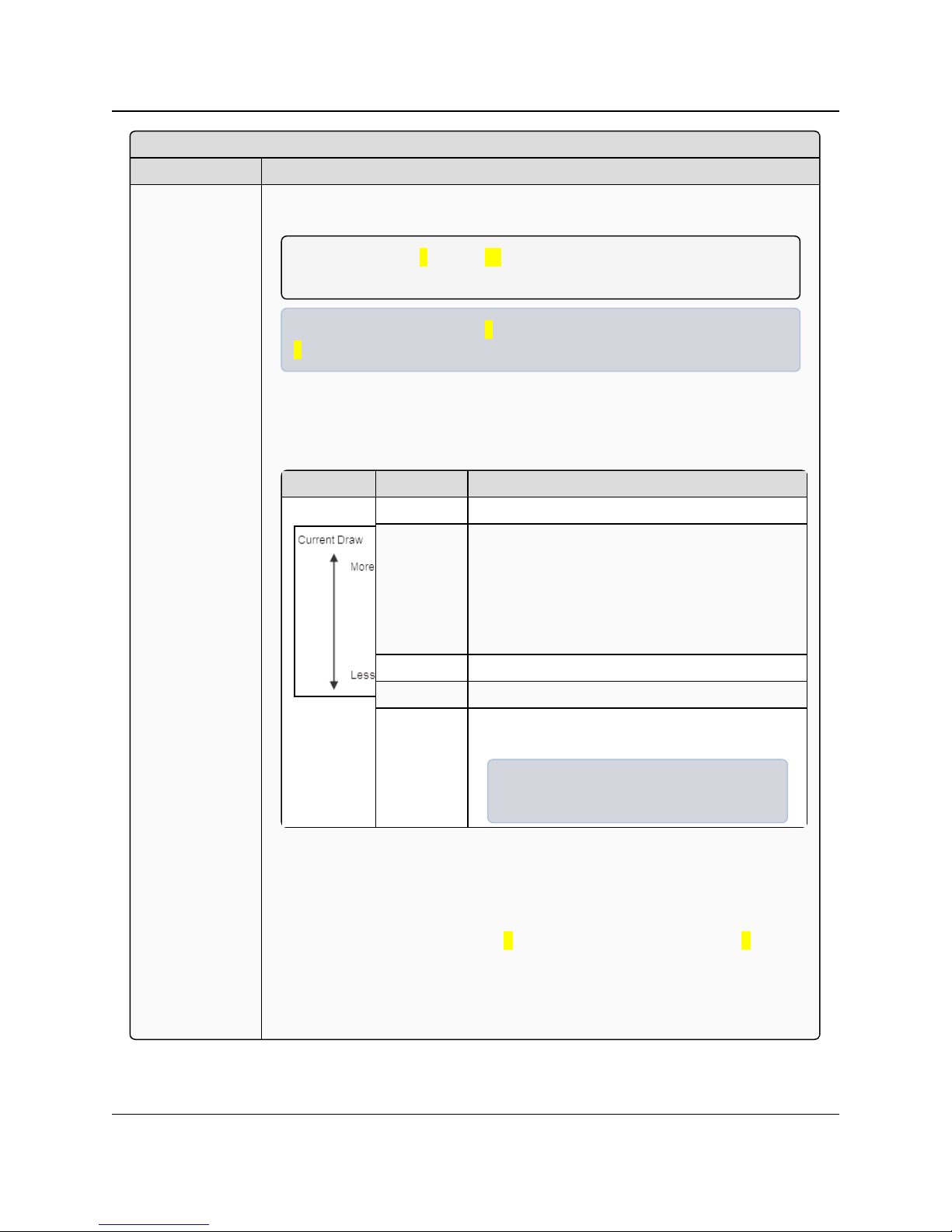
3. Configuring Point-to-MultiPoint Networks
Low Power Mode
Setting Description
Description Allows a MultiPoint Slave to consume less power, primarily by dimming the
radio's LEDs.
Note: When set to 2 through 31, the radio sleeps between slots.
When the radio is asleep, it hears nothing from the Master.
Example: Using a setting of 2 the radio sleeps 1 out of 2 slots; a setting of
3 the radio sleeps 2 out of 3 slots, and so on.
This table shows the changes at different Low Power Mode settings. The actual
current draw depends on many factors. The table below gives only a qualitative
indication of supply current savings. A low number reduces latency and a high
number reduces current consumption.
Setting Description
0 Low power, disabled
1 LEDs dimmed, radio remains awake, radio is
listening to the Master’s transmissions on every
slot, and radio’s data port is shut down if the
RTS line is de-asserted (low).
In this case, the radio needs to be awakened
before it is able to send data to the Master.
2 LEDs dimmed, radio sleeps every other slot.
3 LEDs dimmed, radio sleeps 2 of 3 slots.
4-31 LEDs dimmed, radio sleeps the number of slots
corresponding to the setting.
Example: With a setting of 31 the radio
sleeps 30 of 31 slots.
Notes
l Power savings occur only when the Slave is linked. No power savings occur
when the Slave is transmitting data. Low Power Mode is of little value when a
Slave has a constant, high throughput.
l MCU Speed must be set to 0 and RF Data Rate must be set to 3 for Low
Power Mode to operate properly.
l To communicate to an RS232 port of a radio that is in Low Power Mode, the
RTS line must be held high to wake it up. The radio wakes up within
approximately 20 milliseconds of when RTS goes high.
LRS455-C-U, -T-U, CE-U, TE-U
User & Reference Manual
LUM0016AB Rev May-2018 Page 58 of 90 Copyright © 2018FreeWave
This document is the property of FreeWave Technologies, Inc. and contains proprietary information owned by
FreeWave. This document cannot be reproduced in whole or in part by any means without written permission from
FreeWave Technologies, Inc.
Page 59

3. Configuring Point-to-MultiPoint Networks
Low Power Mode
Setting Description
l If the RTS line on the Slave is held high, the radio remains in normal operation
regardless of the Low Power Mode setting. After RTS is dropped the radio
reverts to Low Power Mode.
l If the radio has the DTR Connect option in the MultiPoint Parameters tab set
to 1 or 2 and if the Low Power Mode is enabled (set to 1-31), the RTS line on
the radio must be asserted for the DTR Connect feature to operate properly.
l To realize full power savings in Low Power Mode, the serial port must be
deactivated between operation.
l To do that the RTS line must be asserted.
l However, since RS485 and RS422 operation uses the RTS line as part of
the data bus, it cannot be asserted to wake-up the radio.
l Therefore, FreeWave recommends that all radios set to RS485 or RS422,
use a Low Power Mode setting of0.
l The diagnostic pins must be disabled or terminated to a cable for the Sleep
current inLower Power Mode to match the specifications.
l To disable the diagnostic pins, verify the Baud Rate tab, the Setup Port
parameter is set to 1 (Main Only).
LRS455-C-U, -T-U, CE-U, TE-U
User & Reference Manual
3.8. Reading Diagnostics in Tool Suite
The Network Diagnostics application provides a place to view diagnostic data for all the devices
connected to the Master in your network in real time. This application is not meant to replicate the
functionality of a Network Management System, but rather it is a tool that can be used for
diagnostics and troubleshooting in the field.
Important!: The Network Diagnostics application is intended for occasional network monitoring or
troubleshooting, not for continuous, long-term collection of diagnostic data.
This section provides basic steps for reading diagnostics using Tool Suite. Tool Suite stores the
diagnostic data in the database and you can import or export a diagnostic file. For information
regarding the data available, recommended best practices, and importing and exporting files
using the Network Diagnostics application, see the ToolSuite User Manual.
Note: To help identify the radios in your network when running Network Diagnostics, set the Radio
Name and Radio ID fields in the Multipoint Parameters tab.
The diagnostic program must be run from the Master radio. Diagnostics requires the following:
l A setting between 1 and 128 in the Diagnostics parameter available in the MultiPoint
Parameters menu on the Master.
l A second computer or serial connection to run the diagnostics software.
LUM0016AB Rev May-2018 Page 59 of 90 Copyright © 2018FreeWave
This document is the property of FreeWave Technologies, Inc. and contains proprietary information owned by
FreeWave. This document cannot be reproduced in whole or in part by any means without written permission from
FreeWave Technologies, Inc.
Page 60
3. Configuring Point-to-MultiPoint Networks
l A diagnostics cable. (Available from FreeWave.)
l Diagnostics software.
LRS455-C-U, -T-U, CE-U, TE-U
User & Reference Manual
Note: For more information about Diagnostics, contact FreeWave Technical Support.
3.8.1. Run Diagnostics using ToolSuite
1. Connect the Master to the computer running Tool Suite.
2. Open ToolSuite and click Network Diagnostics in the Applications window.
3. From the drop-down menu in the Networks section of the ribbon, select the serial network
for which you want to run diagnostics.
Note: If you do not have a network defined, click Add and follow the instructions in the
wizard. For more information, see the ToolSuite User's Manual.
4. From the ribbon, click Start.
5. To stop running diagnostics, click Stop.
Note: If you move away from the Network Diagnostics application without selecting Stop,
the program continues to poll for diagnostic data.
Important!: Tool Suite is not optimized for the collection and management of large amounts of
diagnostic data from continuous polling. Collection of excessive amounts of data results in overall
performance degradation in Tool Suite and network throughput degradation.
LUM0016AB Rev May-2018 Page 60 of 90 Copyright © 2018FreeWave
This document is the property of FreeWave Technologies, Inc. and contains proprietary information owned by
FreeWave. This document cannot be reproduced in whole or in part by any means without written permission from
FreeWave Technologies, Inc.
Page 61

LRS455-C-U, -T-U, CE-U, TE-U
User & Reference Manual
4. Configuring Point-to-Point Networks
Point-to-Point networks are the most basic type of network, and do not require much more than
setting up the basic network, as described in the basic programming and setup chapter.
This section includes:
l A brief quick start to setup a Point-to-Point network.
l An LED chart for LED function within a Point-to-Point network.
l Information about programming the Call Book.
4.1. Point-to-Point Network Quick Start
To establish communications between a pair of FreeWave radios just received from the factory,
complete the steps described below for each radio.
4.1.1. Point-to-Point Network Quick Start (Tool Suite)
1. Connect the radio to the serial port of a computer either through a serial cable or using the
diagnostics cable.
2. Connect the radio to a power source (+6.0 to +27.0 VDC).
Warning! Do not connect the LRS455-C-U, -T-U, CE-U, TE-U series radios to DC
power without terminating the antenna port to a suitable load, such as a 50 ohm antenna,
or an attenuator with a power rating greater than or equal to 2 W. Powering up without a
load attached will damage the radio and void the warranty.
3. Open a Tool Suite session, select the Configuration application, and ensure the correct
port is selected in the Com Port field in the upper left of the Configuration ribbon.
4. From the Networks section of the Configuration ribbon, select the network in which the
radio resides or click Add Network to create a new network in Tool Suite.
LUM0016AB Rev May-2018 Page 61 of 90 Copyright © 2018FreeWave
This document is the property of FreeWave Technologies, Inc. and contains proprietary information owned by
FreeWave. This document cannot be reproduced in whole or in part by any means without written permission from
FreeWave Technologies, Inc.
Page 62

4. Configuring Point-to-Point Networks
LRS455-C-U, -T-U, CE-U, TE-U
User & Reference Manual
5. Click Read Radio in the Configuration ribbon to read the radio's current settings.
l If using a diagnostics cable to connect to the radio, the radio automatically goes into
Setup mode.
l If using a data cable to connect to the radio, you are prompted to press the radio's
Setup button to put the radio in Setup mode. If you are using a board-level radio, use
the interrupt line to short pin 2 and 4.
l When in Setup mode, all three LEDs on the radio display solid green ( ).
6. Click the Operation Mode tab.
7. In the Modem Mode field, select to set the radio in Point-to-Point mode. For example, set
one radio as a Point-to-Point Master (Mode 0) and the other as a Point-to-Point Slave
(Mode 1)
Important!: A network can have only one Master.
8. Click the Baud Rate tab.
9. Change the Baud Rate, Data Parity, and Modbus RTU to match the device that the radio
is to be attached to.
10. Click the Transmission Characteristics tab.
11. Set these parameters so they are identical on all radios in the network:
l Tx Frequency
l Rx Frequency
l Max Packet Size
l Min Packet Size
l RF Data Rate (Only 4 and 5 are approved by the FCC for use in the UnitedStates).
Note: Changing these settings from the factory defaults may help to eliminate interference
from other FreeWave networks.
12. Click the Call Book tab.
13. Enter the Slave serial number in the Master’s Call Book. Enter the Master’s Serial number
in the Slave’s Call Book, or disable Slave Security (in the Slave).
Shortly after both radios are plugged in, they should establish a communications link with
each other and the connection is complete.
LUM0016AB Rev May-2018 Page 62 of 90 Copyright © 2018FreeWave
This document is the property of FreeWave Technologies, Inc. and contains proprietary information owned by
FreeWave. This document cannot be reproduced in whole or in part by any means without written permission from
FreeWave Technologies, Inc.
Page 63
4. Configuring Point-to-Point Networks
LRS455-C-U, -T-U, CE-U, TE-U
User & Reference Manual
4.1.2. Point-to-Point Network Quick Start (Terminal Interface)
1. Connect the radio to the serial port of a computer either through a serial cable or using the
diagnostics cable.
2. Connect the radio to a power source (+6.0 to +27.0 VDC).
Warning! Do not connect the LRS455-C-U, -T-U, CE-U, TE-U series radios to DC
power without terminating the antenna port to a suitable load, such as a 50 ohm antenna,
or an attenuator with a power rating greater than or equal to 2 W. Powering up without a
load attached will damage the radio and void the warranty.
3. Open a terminal emulator session.
4. Connect to COMx (where 'x' is the number of the Com port being connected).
5. Define these settings as:
l Data Rate = 19,200
l Data Bits = 8
l Parity = None
l Stop Bits = 1
l Flow Control = None
6. If you are using the data cable, press the Setup button on the radio or use the interrupt line
to short pin 2 and 4.
If using the diagnostics cable, press <Shift+U>.
l When in Setup mode, all three LEDs on the radio display solid green ( ).
l The Main menu appears on the screen.
7. Press 0 to open the Operation Mode menu.
8. Press 0 to set the radio as a Point-to-Point Master or press 1 to set the radio as Point-toPoint slave.
9. Press <Esc> to return to the Main menu.
Important!: A network can have only one Master.
10. Press 1 in the Main menu.
11. Change the Baud Rate, Data Parity, and Modbus RTU to match the device that the radio
is to be attached to.
Important!: When setting the radio's baud rate, its RS232 data rate is set. The baud rate does
not have to be the same setting for the two radios in the Point-to-Point network.
12. Press <Esc> to return to the Main menu.
13. Press 2 in the Main menu to update the Call Book.
14. Enter the Slave serial number in the Master’s Call Book.
15. Enter the Master’s Serial number in the Slave’s Call Book, or disable Slave Security (in the
Slave).
LUM0016AB Rev May-2018 Page 63 of 90 Copyright © 2018FreeWave
This document is the property of FreeWave Technologies, Inc. and contains proprietary information owned by
FreeWave. This document cannot be reproduced in whole or in part by any means without written permission from
FreeWave Technologies, Inc.
Page 64

4. Configuring Point-to-Point Networks
LRS455-C-U, -T-U, CE-U, TE-U
16. Press 3 in the Main menu.
17. Set these parameters so they are identical on all radios in the network:
l Tx Frequency
l Rx Frequency
l Max Packet Size
l Min Packet Size
l RF Data Rate (Only 4 and 5 are approved by the FCC for use in the United States).
Note: The Tx Frequency and Rx Frequency options, or Frequency Key, are located in the F
submenu after you press 0 to access the Frequency Key menu in Main menu 3.
Note: Changing these settings from the factory defaults may help to eliminate interference
from other FreeWave networks.
Shortly after both radios are plugged in, they should establish a communications link with
each other and the connection is complete.
18. Press <Esc> to exit the Setup menu and resume normal radio operation.
User & Reference Manual
LUM0016AB Rev May-2018 Page 64 of 90 Copyright © 2018FreeWave
This document is the property of FreeWave Technologies, Inc. and contains proprietary information owned by
FreeWave. This document cannot be reproduced in whole or in part by any means without written permission from
FreeWave Technologies, Inc.
Page 65
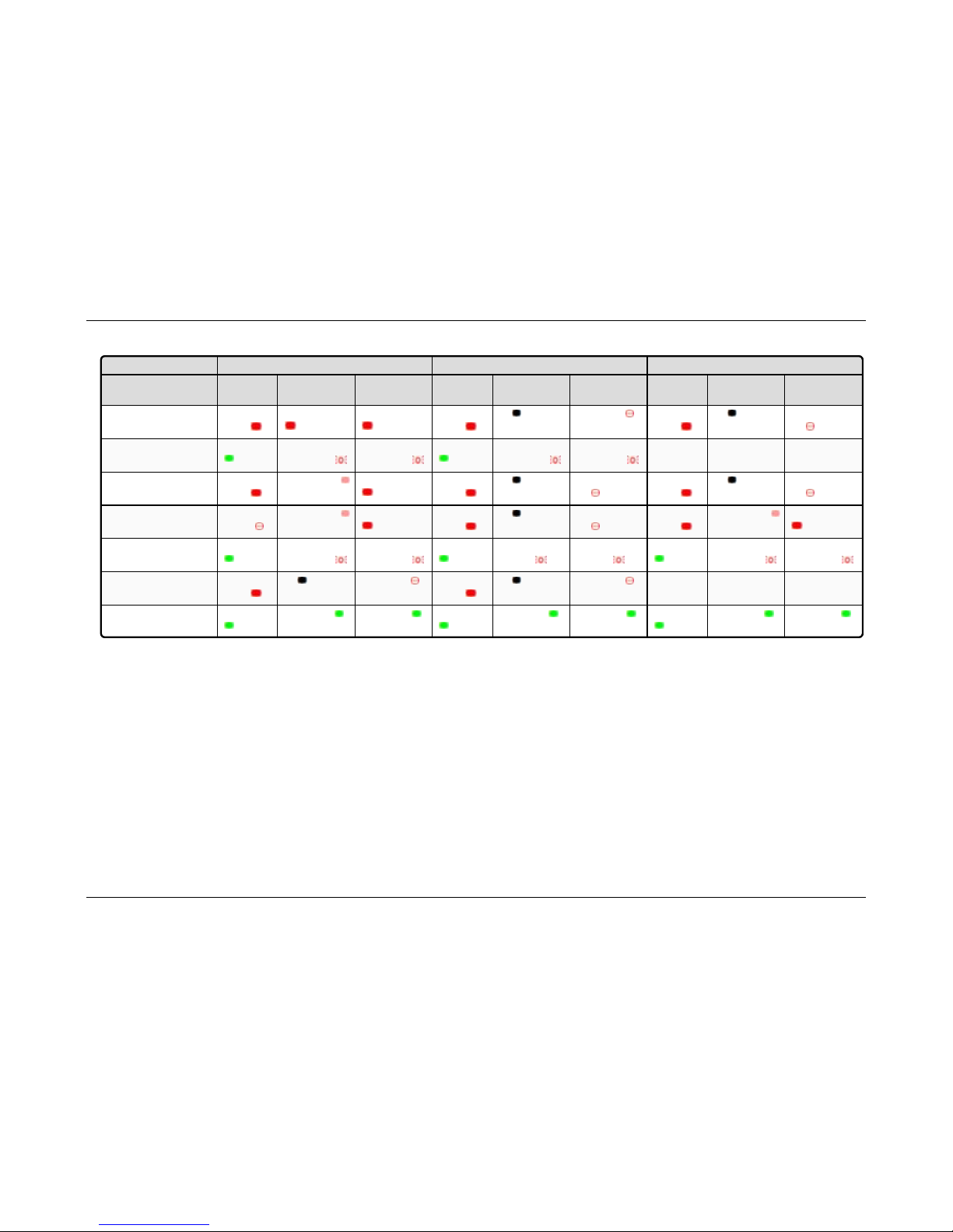
4.2. Point-to-Point Operation LEDs
Master Slave R epeat er
Con dition
Carrier
Detect (CD )
Transmit (Tx)
Clear to Send
(CTS)
Carrier
Detect (CD )
Transmit (Tx)
Clear to Send
(CTS)
Carrier
Detect (CD )
Transmit (Tx)
Clear to Send
(CTS)
Powered, no link Solid red
bright
Solid red bright Solid red bright Solid red
bright
Off
Blinking red
Solid red
bright
Off
Blinking
red
Linked, no Repeater,
sending sparse data
Solid green Intermittent
flashingred
Intermittent
flashingred
Solid green Intermittent
flashingred
Intermittent
flashingred
N/A N/A N/A
Master calling Slave
through Repeater
Solid red
bright
Solid red dim
Solid red bright Solid red
bright
Off
Blinking
red
Solid red
bright
Off
Blinking
red
Master linked to
Repeater, not to Slave
Flashing
orange
Solid red dim
Solid red bright Solid red
bright
Off
Blinking
red
Solid red
bright
Solid red dim
Solid red bright
Repeater linked to Slave Solidgreen Intermittent
flashingred
Intermittent
flashingred
Solid green Intermittent
flash red
Intermittent
flash red
Solid green Intermittent
flashingred
Intermittent
flashingred
Mode 6 - waiting for ATD
command
Solid red
bright
Off
Blinking red
Solid red
bright
Off
Blinking red
N/A N/A N/A
Setup Mode Solid green
Solid green Solid gr een
Solid green
Solid green Solid gr een
Solid green
Solid green Solid gr een
LUM0016AB R ev May-2018 Page 65 of 90 Copyright © 201 8FreeWave
This document is the p roperty of FreeWave Technologies, Inc. and contains proprietary information o wned by FreeWave. This document cannot be reprod uced
in whole or in pa rt by any means wi thout written permission from FreeWave Techn ologies, Inc.
4. Configuring Point-to-Point Networks LRS455-C-U, -T-U, CE-U, TE-U User & Reference Manual
Page 66

4. Configuring Point-to-Point Networks
LRS455-C-U, -T-U, CE-U, TE-U
User & Reference Manual
4.3. Using the Call Book in Point-to-Point Networks
The Call Book is required in Point-to-Point networks. While the Call Book is an option in Point-toMultiPoint networks, FreeWave strongly recommends using the Network ID feature in most
applications. If a large MultiPoint network is implemented using the Call Book and you want to add
a radio to the network, or need to replace a radio, you must physically travel to all radios in the
network and enter the new serial number in the radio's Call Book.
Using the Call Book offers both security and flexibility in determining how FreeWave radios
communicate with each other.
You must set the following for two FreeWave radios to communicate in Point-to-Point mode:
1. The Master’s serial number must be listed in the Slave's Call Book or Slave Security is
turned off in the Slave .
2. The Slave’s serial number must be listed in the Master's Call Book.
3. The Master must be programmed to call the Slave.
The Call Book allows you to incorporate up to 10 FreeWave radios, designate one Repeater, and
designate which Slave the Master calls. To set the Entry to Call option, select the number in the
Entry to Call field, select All to direct the Master to call all Slaves.
Note: To set the Entry to Call option in the terminal interface, enter C at the Call Book menu,
followed by the menu number corresponding to that Slave. To call any available Slave in the list,
enter C then enter A to direct the Master to Call All.
It is important that the Call Book slots (0-9) are filled sequentially starting with slot 0. When a
Master is instructed to Call All, it calls all Slaves listed until it reaches the first serial number of 0000000 (or a blank slot). If a serial number is entered after the all zero number or as a Repeater, the
Master does not recognize it as a valid number.
Note: When entering numbers into the Call Book, you need only define the Repeater in the Master's
Call Book. The Slave Call Book only requires the Master’s serial number. A Repeater need not have
anything listed in its Call Book.
4.4. Set Call Book in Tool Suite
1. In the Tool Suite Configuration application, select the device to program and click the (2)
Call Book tab.
2. In the Number column in Row 0, enter the seven-digit serial number of the radio being
called.
3. In the Repeater 1 column, enter the Repeater’s seven-digit number. If you are not using a
Repeater, leave the column empty.
4. If a Repeater is being used, select the appropriate Entry to Call option in the Master's Call
Book.
5. To apply the changes, select either the Quick or All icon. Tool Suite applies the changes to
the radio.
LUM0016AB Rev May-2018 Page 66 of 90 Copyright © 2018FreeWave
This document is the property of FreeWave Technologies, Inc. and contains proprietary information owned by
FreeWave. This document cannot be reproduced in whole or in part by any means without written permission from
FreeWave Technologies, Inc.
Page 67

4. Configuring Point-to-Point Networks
LRS455-C-U, -T-U, CE-U, TE-U
User & Reference Manual
4.5. Set the Call Book in the Terminal Interface
1. Select (2) Edit Call Book from the main Setup menu to open this window:
Figure 12: HyperTerminal window
2. Enter the number or letter associated with the option you want to select.
3. At the Enter New Number prompt, enter the seven-digit serial number of the radio being
called.
4. The system prompts for Repeater 1’s serial number.
If a Repeater is not being used, press <Esc> and continue with Step 6.
Otherwise, enter the 7-digit serial number of the Repeater.
5. The system prompts for Repeater 2’s serial number.
The LRS455-C-U, -T-U, CE-U, TE-U network supports only one Repeater.
6. Press <Esc> to continue without entering a second Repeater.
The system refreshes the radio’s Call Book menu with the new changes.
7. Repeat Steps 2 to 5 for additional radios in the network.
8. Press <Esc> to return to the Main menu.
LUM0016AB Rev May-2018 Page 67 of 90 Copyright © 2018FreeWave
This document is the property of FreeWave Technologies, Inc. and contains proprietary information owned by
FreeWave. This document cannot be reproduced in whole or in part by any means without written permission from
FreeWave Technologies, Inc.
Page 68

LRS455-C-U, -T-U, CE-U, TE-U
User & Reference Manual
5. Viewing Radio Statistics
When you read a radio the system displays data transmission statistics the radio has gathered
during the most recent session. This information is valuable when you need to know the signal
strength and noise levels of the link. Statistics are gathered during each data link and are reset
when the next link begins.
In addition, you can view more data transmission characteristics in the Network Diagnostics
application. For information about running network diagnostics using Tool Suite, see the Tool
Suite User Manual.
5.0.1. View Statistics in Tool Suite
1. In the Tool Suite Configuration application, clickRead Radio, and then click the Device
Information tab.
2. Review the statistics. Each statistic is described in detail in the sections below.
Note: You can also view the same statistics using the Setup Terminal option in Tool Suite.
5.0.2. View Radio Transmission Characteristics in the Terminal Interface
1. Select (4) Show Radio Statistics from the Setup main menu.
2. Review the radio statistics. Each statistic is described in detail in the sections below.
5.1. Antenna Reflected Power
Note: Displayed in Tool Suite. Not currently supported.
LUM0016AB Rev May-2018 Page 68 of 90 Copyright © 2018FreeWave
This document is the property of FreeWave Technologies, Inc. and contains proprietary information owned by
FreeWave. This document cannot be reproduced in whole or in part by any means without written permission from
FreeWave Technologies, Inc.
Page 69

5. Viewing Radio Statistics
LRS455-C-U, -T-U, CE-U, TE-U
User & Reference Manual
5.2. Antenna Rev
This statistic is available only in the terminal interface and measures the antenna power when
data is received from the perspective of the local device.
l A reading of 0 to 5 is good; 5 to 20 is marginal;
l 20 or higher indicates that the connections should be inspected for loose connections and
cable quality.
l A reading of 30 or higher indicates a definite problem in the system.
l The most likely cause is a cable issue between the radio and the antenna.
5.3. Antenna Fwd
This statistic is available only in the terminal interface and measures the antenna power when
data is transmitted from the perspective of the local device. A reading of 0 to 5 is good; 5 to 20 is
marginal; 20 or higher indicates that the connections should be inspected for loose connections
and cable quality. A reading of 30 or higher indicates a definite problem in the system. The most
likely cause is a cable issue between the radio and the antenna.
5.4. Master-Slave Distance
The physical distance between the slave radio and the master radio in your network. This number
is measured in meters and is more accurate at distances over 2.5 miles.
5.5. Number of Disconnects
The number of times the link between the Master and the Slave is broken and the radios lose
Carrier Detect.
The value indicates the total number of disconnects that have occurred from the time the radio is
powered on until the radio is put into Setup mode. Under ideal operating conditions, the number of
disconnects should be 0. One or more disconnects may indicate a weak link, the presence of
severe interference problems on any of the radios in the link.
Note: In Tool Suite, the disconnect information is available in the Summary View in the Network
Diagnostics application.
5.6. Noise Level
The Noise Level indicates the level of background noise and interference at this radio. The
number is an average of the noise levels measured at each frequency in the radio’s frequency hop
table.
The individual measurement values at each frequency hop channel are shown in the frequency
table. If you are viewing statistics in Setup Terminal or another terminal emulator, press
<Enter> when the Radio Statistics menu displays to view the frequency table.
LUM0016AB Rev May-2018 Page 69 of 90 Copyright © 2018FreeWave
This document is the property of FreeWave Technologies, Inc. and contains proprietary information owned by
FreeWave. This document cannot be reproduced in whole or in part by any means without written permission from
FreeWave Technologies, Inc.
Page 70

5. Viewing Radio Statistics
l Ideally, noise levels should be below -112 dBm and the difference between the average
LRS455-C-U, -T-U, CE-U, TE-U
User & Reference Manual
signal level and average noise level should be 26 or more.
l Noise levels significantly higher than this are an indication of a high level of interference that
may degrade the performance of the link.
l High noise levels can often be mitigated with band pass filters, antenna placement or
antenna polarization.
5.7. Signal Level
The level of received signal at this radio. For each of these, the signal source is the radio that
transmits to it. The number is an average of the received signal levels measured at each
frequency in the radio's frequency hop table.
The individual measurement values at each frequency hop channel are shown in the frequency
table. If you are viewing statistics in the Setup Terminal application or another terminal
emulator, press <Enter> when the Radio Statistics menu displays to view the frequency table.
l For a reliable link, the margin should be at least 26 dB.
l Low average signal levels can often be corrected with higher gain antennas or better
antenna placement.
Note: See the installation manual for antenna and regulating requirements.
5.8. Rate %
Measures the percentage of data packets that were successfully transmitted from the Master to
the Slave.
l A number of 75 or higher indicates a robust link that provides very good performance even
at high data transmission rates.
l A number of 74 lower indicates a weak or marginal link that provides lower data throughput.
5.9. Radio Temperature
The current operating temperature of the radio in degrees Celsius. For proper operation, a
FreeWave radio must be in the temperature range of -30° to +60° C.
LUM0016AB Rev May-2018 Page 70 of 90 Copyright © 2018FreeWave
This document is the property of FreeWave Technologies, Inc. and contains proprietary information owned by
FreeWave. This document cannot be reproduced in whole or in part by any means without written permission from
FreeWave Technologies, Inc.
Page 71

LRS455-C-U, -T-U, CE-U, TE-U
User & Reference Manual
6. Release Notes
These sections describe the updates and known limitations in each firmware version for the
identified model numbers, as of this document's release. The latest documentation and firmware
versions are available on the FreeWave Web site at www.freewave.com.
Version 1.77
Release Date: January 2015
Additions and Changes
l Setting to RS485 is now stable.
l This was a software-only fix and no hardware or other functionality changes were
required.
Known Limitations and Workarounds
l No known additional limitations.
Version 1.74
Release Date: April 2013
Additions and Changes
l Use of frequency 452.25 MHz (CH 2760) now functions correctly.
l This was a software only fix, and no hardware or other functionality changes were
required.
LUM0016AB Rev May-2018 Page 71 of 90 Copyright © 2018FreeWave
This document is the property of FreeWave Technologies, Inc. and contains proprietary information owned by
FreeWave. This document cannot be reproduced in whole or in part by any means without written permission from
FreeWave Technologies, Inc.
Page 72

6. Release Notes
LRS455-C-U, -T-U, CE-U, TE-U
User & Reference Manual
Known Limitations and Workarounds
l The RF Data Rate parameter displays 0 to 5 as valid entries.
l In LRS455-C and LRS455-T models, only RF Data Rates 4 and 5 are valid and
accepted.
l Setting 2 in the Use Break to Access Setup parameter is NOT supported.
l Use option 1 to use the Break to Access Setup functionality.
l Operation Mode 6 is NOT supported.
l In some cases, if the Slave is powered up before the Master, the Slave may not maintain its
link to the Master.
l To ensure the Slave maintains its link, power up the Master prior to powering up a
connectingSlave.
l A Slave doe NOT re-link to the Master immediately if the Master is momentarily powered
off.
l If a Slave is communicating through a Repeater, the Slave is unavailable in Network
Diagnostics within ToolSuite.
l Local Diagnostics in Tool Suite is NOT supported.
l The Tx remote LED output is currently unavailable.
l Over the air firmware updates via the data port are NOT recommended at this time.
Version 1.72
Additions and Changes
l Crystal drift firmware fix. No visual changes or updates to functionality.
Known Limitations and Workarounds
l The RF Data Rate parameter shows 0 to 5 as valid entries.
l In LRS455-C models, only RF Data Rates 4 and 5 are valid and accepted.
l Setting 2 in the Use Break to Access Setup parameter is NOT supported.
l Use option 1 to use the Break to Access Setup functionality.
l Operation Mode 6 is NOT supported.
l In some cases, if the Slave is powered up before the Master, the Slave may not maintain its
link to the Master.
l To ensure the Slave maintains its link, power up the Master prior to powering up a
connectingSlave.
l If a Slave is communicating through a Repeater, the Slave is unavailable in Network
Diagnostics in Tool Suite.
l Local Diagnostics in Tool Suite is NOT supported.
l The Tx remote LED output is currently unavailable.
LUM0016AB Rev May-2018 Page 72 of 90 Copyright © 2018FreeWave
This document is the property of FreeWave Technologies, Inc. and contains proprietary information owned by
FreeWave. This document cannot be reproduced in whole or in part by any means without written permission from
FreeWave Technologies, Inc.
Page 73

6. Release Notes
Version 1.71
Release Date: May 2011
Additions and Changes
l Fixes to support VCO Range testing.
Version 1.70
Release Date: February 2011
Additions and Changes
l Miscellaneous fixes. No details provided.
Known Limitations and Workarounds
l Point-to-Point Repeaters are NOT supported
Version 1.69d9
Release Date: October 2010
Additions and Changes
LRS455-C-U, -T-U, CE-U, TE-U
User & Reference Manual
l Transmitter response fixed.
Version 1.67o
Release Date: August 2010
Known Limitations and Workarounds
l Setting Master Packet Repeat to 0 and Modbus RTU to 1 results in a large data
transmission delay.
l Master Packet Repeat should be set to 1 or higher if the Modbus RTU setting is
enabled.
LUM0016AB Rev May-2018 Page 73 of 90 Copyright © 2018FreeWave
This document is the property of FreeWave Technologies, Inc. and contains proprietary information owned by
FreeWave. This document cannot be reproduced in whole or in part by any means without written permission from
FreeWave Technologies, Inc.
Page 74

LRS455-C-U, -T-U, CE-U, TE-U
User & Reference Manual
7. Additional Radio Information
This section contains additional important information about the FreeWave radios described in
this manual.
l Operational RS422 and RS485 Information
l RS422 and RS485 full duplex pin-outs
l RS485 half duplex pin-outs
7.1. Operational RS422 and RS485 Information
For RS422 and RS485, the FreeWave radio can drive 32 standard unit loads and loads the bus
with only 1/8 unit load. This allows a maximum of 256 devices on the bus if all of the line receivers
have 1/8 unit load.
RS422 is used for 4-wire or full duplex communication with one Master and multiple Slave radios.
l The Master radio keeps the line driver asserted at all times.
l The maximum line length is 4,000 feet using two, 120 ohm twisted pair cables with a fifth
wire for data common.
l RS485 full duplex using 4-wire plus common is the same as RS422, except the system can
have multiple Masters on the bus.
The most common operation of RS485 is a two-wire comprised of a 120 ohm impedance single
twisted pair.
In this system the loading of the FreeWave radio is as described above, which allows up to 256 1/8
unit load units on the bus.
Maximum line length is also 4,000 feet with a third wire required for data common.
The FreeWave radio checks the line to be certain no other device is transmitting before enabling
the line driver for data transmission.
LUM0016AB Rev May-2018 Page 74 of 90 Copyright © 2018FreeWave
This document is the property of FreeWave Technologies, Inc. and contains proprietary information owned by
FreeWave. This document cannot be reproduced in whole or in part by any means without written permission from
FreeWave Technologies, Inc.
Page 75
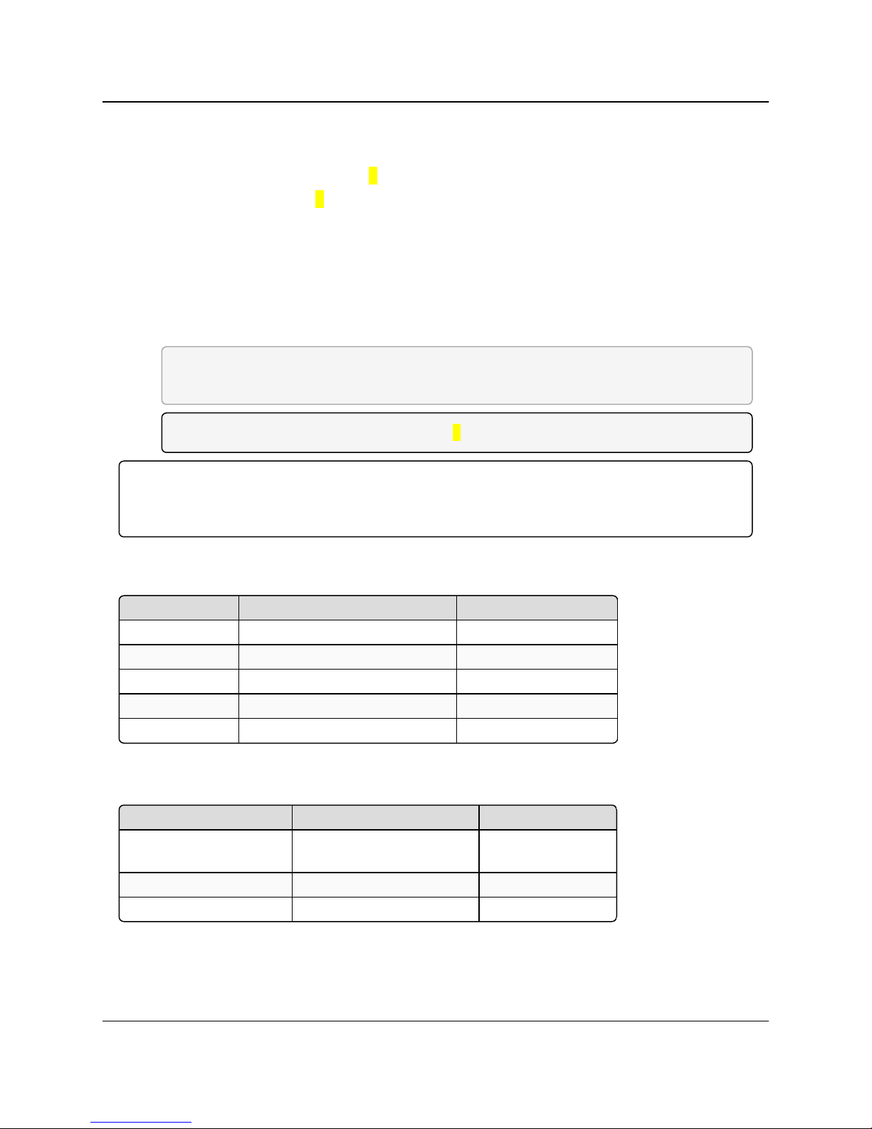
7. Additional Radio Information
Function Bare Board Pin Number DB-9 Pin Number
RX+ 7 3
RX- 9 7
TX+ 5 2
TX- 10 8
Signal Ground 4 or 6 5
Function Bare Board Pin Number DB-9 Pin Number
Wire to both bins for Bus+Short 5 and 7 Short 2 and 3
Wire to both pins for Bus - Short 9 and 10 Short 7 and 8
Signal Ground 4 or 6 5
LRS455-C-U, -T-U, CE-U, TE-U
User & Reference Manual
When setting the radio to RS485:
1. Enable Modbus.
2. Set Master Packet Repeat to 3 in the radios that use RS485.
3. Set Turn Off Delay to 4.
The Turn Off Delay setting in the menu is used to control the length of time the transmitter driver
stays asserted after data transmission has finished.
l This is needed to allow the last transmitted character to reach the end of a long line and is
normally set to one character length of time.
l This setting also allows three complete reflections to the end of the line to ensure the ringing
on the line has fully dampened before releasing the bus to another device.
FREEWAVE Recommends: Shorter line lengths may use shorter delays, but four onequarter-character delay times are recommended.
Note: In Modbus, a Turn Off Delay setting of 0 causes internal timing errors.
Important!: There is no provision for hand shaking in any of the above modes of operation.
Data rates above 9600 bps in RF Data Rate = 5 and above 19200 bps in RF Date Rate = 4 are NOT
recommended without a protocol that can handle error detection properly.
7.1.1. RS422 and RS485 Full Duplex Pin-Outs
7.1.2. RS485 Half Duplex Pin-Out
LUM0016AB Rev May-2018 Page 75 of 90 Copyright © 2018FreeWave
This document is the property of FreeWave Technologies, Inc. and contains proprietary information owned by
FreeWave. This document cannot be reproduced in whole or in part by any means without written permission from
FreeWave Technologies, Inc.
Page 76

7. Additional Radio Information
7.2. Attenuator for Testing
LRS455-C-U, -T-U, CE-U, TE-U
User & Reference Manual
LUM0016AB Rev May-2018 Page 76 of 90 Copyright © 2018FreeWave
This document is the property of FreeWave Technologies, Inc. and contains proprietary information owned by
FreeWave. This document cannot be reproduced in whole or in part by any means without written permission from
FreeWave Technologies, Inc.
Page 77

LRS455-C-U, -T-U, CE-U, TE-U
LRS455 Technical Specifications
Specification Description
Transmitter
Frequency 435-470 MHz
Output Power Programmable up to 2 W
Range 70 miles with clear line of sight
Modulation 2 and 4 level GFSK
Occupied Bandwidth 12.5 kHz
Frequency Channels 5600 Channels @ 6.25 kHz
Receiver
Sensitivity (2 level) -112 dBm at 9,600 bps and BER 10
-6
(4 level) -100 dBm at 19,200 bps BER 10
-6
Data Transmission
Error Detection 32 bit CRC, Retransmit on error
Link Throughput 9.6 Kbps at 2 level GFSK
19.2 Kbps at 4 level GFSK
Data Interface RS232 / RS422 / RS485 or TTL
User & Reference Manual
Appendix A: LRS455 Technical Specifications
Specifications may change at any time without notice. For the most up-to-date specifications
information, see the product's data sheet available at www.FreeWave.com.
LUM0016AB Rev May-2018 Page 77 of 90 Copyright © 2018FreeWave
This document is the property of FreeWave Technologies, Inc. and contains proprietary information owned by
FreeWave. This document cannot be reproduced in whole or in part by any means without written permission from
FreeWave Technologies, Inc.
Page 78
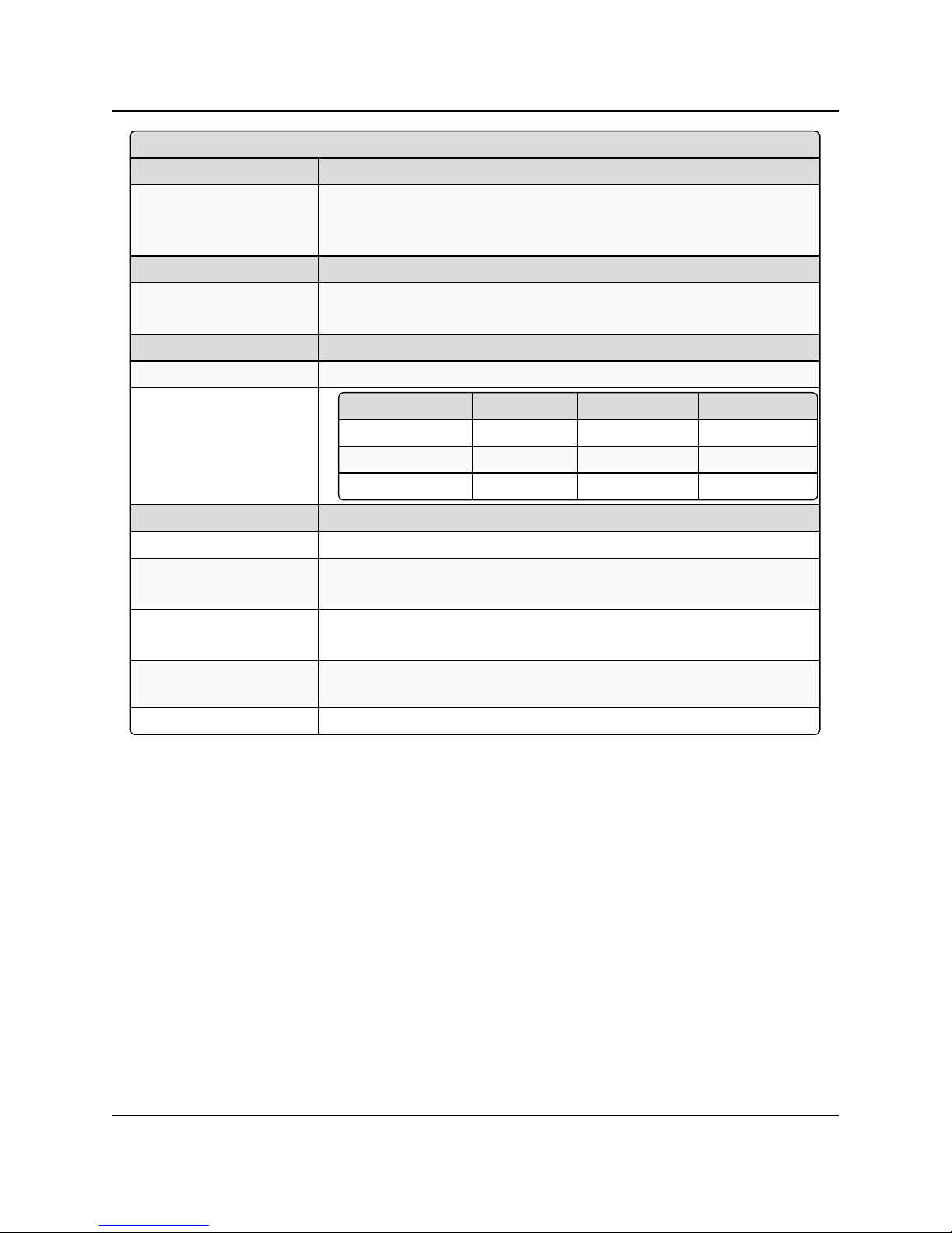
Appendix A: LRS455 Technical Specifications
LRS455 Technical Specifications
Specification Description
Data Connector Board Level: 10 pin header with locking ramp, 0.1 inch spacing power /
data connector.
Enclosed: DB9
Diagnostics
Connector Board Level: Separate 20-pin connector
Enclosed: 3-pin PCB header
Power Requirement
Operating Voltage +6.0 to +27.0 VDC
Current Drain
Mode +6 VDC +12 VDC +27 VDC
Transmit 1.5 A 0.75 A 0.34 A
Receive 200 mA 100 mA 45 mA
Idle 50 mA 25 mA 12 mA
General Information
Operating Temperature -30 °C to + 60 °C
Dimensions 128 L x 61.8 W x 19.7 H (mm)
Enclosed: 173 L x 112 W x 35 H (mm)
Weight 74.4 g
Enclosed: 605 g
External Antenna
Connector
SMA (board level), TNC (enclosure)
Humidity 0 to 95% non-condensing
LRS455-C-U, -T-U, CE-U, TE-U
User & Reference Manual
LUM0016AB Rev May-2018 Page 78 of 90 Copyright © 2018FreeWave
This document is the property of FreeWave Technologies, Inc. and contains proprietary information owned by
FreeWave. This document cannot be reproduced in whole or in part by any means without written permission from
FreeWave Technologies, Inc.
Page 79
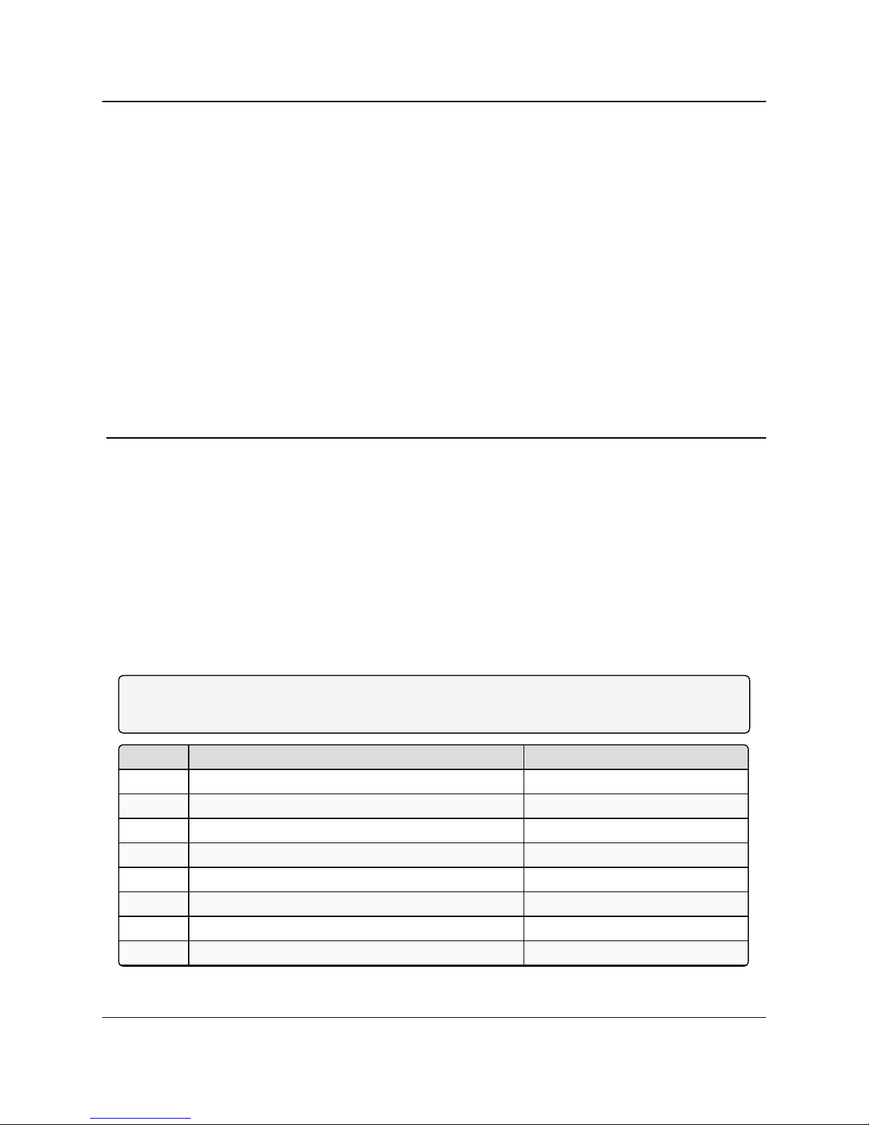
LRS455-C-U, -T-U, CE-U, TE-U
Pin Assignment Color on ACS3610xx Cable
1 B+ input Red
2 Interrupt (temporarily ground to invoke menu) Brown
3 Data Terminal Ready (DTR) Orange
4 Ground Black
5 Transmit Data (TXD) Yellow
6 Ground Black
7 Receive Data (RXD) Green
8 Carrier Detect (DCD) Blue
User & Reference Manual
Appendix B: RF Board Pin-Out
The LRS455 Wireless Data Radio series radios are available in both TTL and RS232 versions.
l The TTL versions use reverse polarity from standard RS232 at 0 to 5 Volt levels.
l All pin descriptions and pin numbering are the same as the RS232 version.
l The RS232 versions use standard RS232 polarity and voltage levels for all of the RS232
signal lines (DTR, Transmit Data, Receive Data, Carrier Detect, RTS, and Clear to Send)
and TTL standard polarity and voltage level for the Interrupt pin.
l Pin 1 - B+ Power input.
l Pin 2 - Interrupt (INT) – Input – A 0 volt level on this pin switches the radio into Setup
mode.
Note: Pin 1 on the board-level radios is the pin farthest from the three LEDs and pin 10 is the closest
to the LEDs.
LUM0016AB Rev May-2018 Page 79 of 90 Copyright © 2018FreeWave
This document is the property of FreeWave Technologies, Inc. and contains proprietary information owned by
FreeWave. This document cannot be reproduced in whole or in part by any means without written permission from
FreeWave Technologies, Inc.
Page 80

Appendix B: RF Board Pin-Out
Pin Assignment Color on ACS3610xx Cable
9 Request to Send (RTS) Violet (purple)
10 Clear to Send (CTS) Gray
LRS455-C-U, -T-U, CE-U, TE-U
User & Reference Manual
LUM0016AB Rev May-2018 Page 80 of 90 Copyright © 2018FreeWave
This document is the property of FreeWave Technologies, Inc. and contains proprietary information owned by
FreeWave. This document cannot be reproduced in whole or in part by any means without written permission from
FreeWave Technologies, Inc.
Page 81

LRS455-C-U, -T-U, CE-U, TE-U
Pin Assignment Signal Definition
1 CD Carrier Detect Output Used to show an RF connection between radios.
2 TX Transmit Data Output Used to transmit data bits serially from the radios to the
system device.
3 RX Receive Data Input Used to receive data bits serially from the system
device connected to the radios.
4 DTR Data
TerminalReady
Input Used only in radios in Point-to-Point Slave/Master
switchable mode or for DTR Connect.
5 GND Ground Signal return for all signal lines shared with Pin 9.
6 DSR Data Set
Ready
Output Always high when the radio is powered from the 2.5 mm
power connector. Indicated power is on to the radio.
Also, this pin can be used for +12 Volts when powering
the radios directly through the RS232 port.
This is not used on the OEM module.
7 RTS Request to
Send
Input The radio does not recognize RTS for flow control. RTS
is used as a control line in RTS/CTS mode.
8 CTS Clear to Send Output This signal is used to tell the system device connected
to the radio that the radio is ready to receive data.
When asserted, the radio accepts data, when deasserted, the radio does not accept data.
This should always be used for data rates above 38.4
KB or there is a risk of lost data if an RF link is not very
robust.
9 GND Ground Signal return for all signal lines shared with Pin 5.
User & Reference Manual
Appendix C: RS232 Pin Assignments
LUM0016AB Rev May-2018 Page 81 of 90 Copyright © 2018FreeWave
This document is the property of FreeWave Technologies, Inc. and contains proprietary information owned by
FreeWave. This document cannot be reproduced in whole or in part by any means without written permission from
FreeWave Technologies, Inc.
Page 82

LRS455-C-U, -T-U, CE-U, TE-U
Channel# Frequency Channel # Frequency Channel # Frequency
0 435.000 2060 447.875 4120 460.750
20 435.125 2080 448.000 4140 460.875
40 435.250 2100 448.125 4160 461.000
60 435.375 2120 448.250 4180 461.125
80 435.500 2140 448.375 4200 461.250
100 435.625 2160 448.500 4220 461.375
120 435.750 2180 448.625 4240 461.500
140 435.875 2200 448.750 4260 461.625
160 436.000 2220 448.875 4280 461.750
180 436.125 2240 449.000 4300 461.875
200 436.250 2260 449.125 4320 462.000
220 436.375 2280 449.250 4340 462.125
User & Reference Manual
Appendix D: Frequency List
The LRS455-C-U, -T-U, CE-U, TE-U radios tune from 435 MHz to 470 MHz with a tuning
resolution of 6.25 KHz. This gives a total of 5600 available channels. Using the license allowed
frequency, the channel number can be determined using this formula.
Channel number = F
Note: This is a partial list. If the required frequency is not listed use the F
appropriate channel number.
MHz
(160) – 69600
MHz
formula to obtain the
LUM0016AB Rev May-2018 Page 82 of 90 Copyright © 2018FreeWave
This document is the property of FreeWave Technologies, Inc. and contains proprietary information owned by
FreeWave. This document cannot be reproduced in whole or in part by any means without written permission from
FreeWave Technologies, Inc.
Page 83

Appendix D: Frequency List
Channel# Frequency Channel # Frequency Channel # Frequency
240 436.500 2300 449.375 4360 462.250
260 436.625 2320 449.500 4380 462.375
280 436.750 2340 449.625 4400 462.500
300 436.875 2360 449.750 4420 462.625
320 437.000 2380 449.875 4440 462.750
340 437.125 2400 450.000 4460 462.875
360 437.250 2420 450.125 4480 463.000
380 437.375 2440 450.250 4500 463.125
400 437.500 2460 450.375 4520 463.250
420 437.625 2480 450.500 4540 463.375
440 437.750 2500 450.625 4560 463.500
460 437.875 2520 450.750 4580 463.625
480 438.000 2540 450.875 4600 463.750
500 438.125 2560 451.000 4620 463.875
520 438.250 2580 451.125 4640 464.000
540 438.375 2600 451.250 4660 464.125
560 438.500 2620 451.375 4680 464.250
580 438.625 2640 451.500 4700 464.375
600 438.750 2660 451.625 4720 464.500
620 438.875 2680 451.750 4740 464.625
640 439.000 2700 451.875 4760 464.750
660 439.125 2720 452.000 4780 464.875
680 439.250 2740 452.125 4800 465.000
700 439.375 2760 452.250 4820 465.125
720 439.500 2780 452.375 4840 465.250
740 439.625 2800 452.500 4860 465.375
760 439.750 2820 452.625 4880 465.500
780 439.875 2840 452.750 4900 465.625
800 440.000 2860 452.875 4920 465.750
820 440.125 2880 453.000 4940 465.875
840 440.250 2900 453.125 4960 466.000
860 440.375 2920 453.250 4980 466.125
880 440.500 2940 453.375 5000 466.250
LRS455-C-U, -T-U, CE-U, TE-U
User & Reference Manual
LUM0016AB Rev May-2018 Page 83 of 90 Copyright © 2018FreeWave
This document is the property of FreeWave Technologies, Inc. and contains proprietary information owned by
FreeWave. This document cannot be reproduced in whole or in part by any means without written permission from
FreeWave Technologies, Inc.
Page 84

Appendix D: Frequency List
Channel# Frequency Channel # Frequency Channel # Frequency
900 440.625 2960 453.500 5020 466.375
920 440.750 2980 453.625 5040 466.500
940 440.875 3000 453.750 5060 466.625
960 441.000 3020 453.875 5080 466.750
980 441.125 3040 454.000 5100 466.875
1000 441.250 3060 454.125 5120 467.000
1020 441.375 3080 454.250 5140 467.125
1040 441.500 3100 454.375 5160 467.250
1060 441.625 3120 454.500 5180 467.375
1080 441.750 3140 454.625 5200 467.500
1100 441.875 3160 454.750 5220 467.625
1120 442.000 3180 454.875 5240 467.750
1140 442.125 3200 455.000 5260 467.875
1160 442.250 3220 455.125 5280 468.000
1180 442.375 3240 455.250 5300 468.125
1200 442.500 3260 455.375 5320 468.250
1220 442.625 3280 455.500 5340 468.375
1240 442.750 3300 455.625 5360 468.500
1260 442.875 3320 455.750 5380 468.625
1280 443.000 3340 455.875 5400 468.750
1300 443.125 3360 456.000 5420 468.875
1320 443.250 3380 456.125 5440 469.000
1340 443.375 3400 456.250 5460 469.125
1360 443.500 3420 456.375 5480 469.250
1380 443.625 3440 456.500 5500 469.375
1400 443.750 3460 456.625 5520 469.500
1420 443.875 3480 456.750 5540 469.625
1440 444.000 3500 456.875 5560 469.750
1460 444.125 3520 457.000 5580 469.875
1480 444.250 3540 457.125 5600 470.000
1500 444.375 3560 457.250
1520 444.500 3580 457.375
1540 444.625 3600 457.500
LRS455-C-U, -T-U, CE-U, TE-U
User & Reference Manual
LUM0016AB Rev May-2018 Page 84 of 90 Copyright © 2018FreeWave
This document is the property of FreeWave Technologies, Inc. and contains proprietary information owned by
FreeWave. This document cannot be reproduced in whole or in part by any means without written permission from
FreeWave Technologies, Inc.
Page 85

Appendix D: Frequency List
Channel# Frequency Channel # Frequency Channel # Frequency
1560 444.750 3620 457.625
1580 444.875 3640 457.750
1600 445.000 3660 457.875
1620 445.125 3680 458.000
1640 445.250 3700 458.125
1660 445.375 3720 458.250
1680 445.500 3740 458.375
1700 445.625 3760 458.500
1720 445.750 3780 458.625
1740 445.875 3800 458.750
1760 446.000 3820 458.875
1780 446.125 3840 459.000
1800 446.250 3860 459.125
1820 446.375 3880 459.250
1840 446.500 3900 459.375
1860 446.625 3920 459.500
1880 446.750 3940 459.625
1900 446.875 3960 459.750
1920 447.000 3980 459.875
1940 447.125 4000 460.000
1960 447.250 4020 460.125
1980 447.375 4040 460.250
2000 447.500 4060 460.375
2020 447.625 4080 460.500
2040 447.750 4100 460.625
LRS455-C-U, -T-U, CE-U, TE-U
User & Reference Manual
LUM0016AB Rev May-2018 Page 85 of 90 Copyright © 2018FreeWave
This document is the property of FreeWave Technologies, Inc. and contains proprietary information owned by
FreeWave. This document cannot be reproduced in whole or in part by any means without written permission from
FreeWave Technologies, Inc.
Page 86

LRS455-C-U, -T-U, CE-U, TE-U
Operation Mode Default MultiPoint Parameters Default
Point-to-Point Slave 1 (1) MASTER PACKET REPEAT 0
Set Baud Rate Default (2) MAX SLAVE RETRY 9
Baud Rate 19200 (3) RETRY ODDS 0
(A) Data Parity 0 (4) DTR CONNECT 0
(B) Modbus RTU 0 (6) NETWORK ID 255
(C) RS232/485 0 (7) RESERVED -
(D) Setup Port 3 (8) MULTI MASTER SYNC 0
(E) TurnOffDelay/OnDelay 0/0 (9) 1 PPS ENABLE DELAY 255
(F) Flow Control 0 (A) SLAVE/REPEATER 0
Radio Parameters Default (B) DIAGNOSTICS 0
(1) MAX PACKET SIZE 9 (C) SUBNET ID Disabled
(2) MIN PACKET SIZE 1 Rx ID F
(3) XMT RATE 1 Tx ID F
(4) RF DATA RATE 5 (D) RADIO ID Not Set
(5) RF XMT POWER 10 (E) Local Mode 0
(6) SLAVE SECURITY 0 (F) Radio Name blank
(7) RTS TO CTS 0
(8) RETRY TIMEOUT 255
User & Reference Manual
Appendix E: Factory Default Settings
FreeWave LRS455-C-U, -T-U, CE-U, TE-U radios ship from the factory with these default
settings:
LUM0016AB Rev May-2018 Page 86 of 90 Copyright © 2018FreeWave
This document is the property of FreeWave Technologies, Inc. and contains proprietary information owned by
FreeWave. This document cannot be reproduced in whole or in part by any means without written permission from
FreeWave Technologies, Inc.
Page 87

Appendix E: Factory Default Settings
Operation Mode Default MultiPoint Parameters Default
(9) LOW POWER MODE 0
(A) High Noise 0
(B) MCU Speed 0
(C) Remote LED 0
LRS455-C-U, -T-U, CE-U, TE-U
User & Reference Manual
LUM0016AB Rev May-2018 Page 87 of 90 Copyright © 2018FreeWave
This document is the property of FreeWave Technologies, Inc. and contains proprietary information owned by
FreeWave. This document cannot be reproduced in whole or in part by any means without written permission from
FreeWave Technologies, Inc.
Page 88

LRS455-C-U, -T-U, CE-U, TE-U
User & Reference Manual
Appendix F: FreeWave Legal Information
FreeWave Technologies, Inc. products may be subject to control by the Export Administration Regulations
(EAR) and/or the International Traffic in Arms Regulations (ITAR). Export, re-export, or transfer of these
products without required authorization from the U.S. Department of Commerce, Bureau of Industry and
Security, or the U.S. Department of State, Directorate of Defense Trade Controls, as applicable, is
prohibited. Any party exporting, re-exporting, or transferring FreeWave products is responsible for
obtaining all necessary U.S. government authorizations required to ensure compliance with these and other
applicable U.S. laws. Consult with your legal counsel for further guidance.
Input voltage for these models is +6.0 to +27.0 VDC.
Models LRS455-C-U, LRS455-CE-U, LRS455-T-U, LRS455-TE-U are suitable for use in Class 1, Division 2,
Groups A, B, C, and D or non-hazardous locations only. Do not connect or disconnect any connectors while the
circuit is live unless the area is known to be non-hazardous.
UL Notifications / Warnings - Class1 Div2
Warning! EXPLOSION HAZARD! - Substitution of components may impair suitability for Class 1,
Division 2.
Warning! DO NOT REMOVE or insert the diagnostics cable while the circuit is live!
UL Power Source
Important!: Input power shall be derived from a single Class 2 power source.
FCC Notifications
This device complies with part 15 of the FCC rules. Operation is subject to the following two conditions: 1) This
device may not cause harmful interference and 2) this device must accept any interference received, including
interference that may cause undesired operation.
The content of this guide covers FreeWave Technologies, Inc. models sold under FCC ID: KNY821191151819.
LUM0016AB Rev May-2018 Page 88 of 90 Copyright © 2018FreeWave
This document is the property of FreeWave Technologies, Inc. and contains proprietary information owned by
FreeWave. This document cannot be reproduced in whole or in part by any means without written permission from
FreeWave Technologies, Inc.
Page 89

Appendix F: FreeWave Legal Information
All models sold under the FCC ID(s) listed above must be installed professionally and are only approved for use
when installed in devices produced by FreeWave Technologies or third party OEMs with the express written
approval of FreeWave Technologies, Inc. Changes or modifications should not be made to the device.
FCC NEMA Installation and Label
Where applicable, the models described in this guide must be installed in a NEMA enclosure. When any
FreeWave Technologies, Inc. module is placed inside an enclosure, a label must be placed on the outside of the
enclosure. The label must include the text "Contains Transmitter Module with FCC ID: KNY821191151819."
FCC Notification of Power Warning
The covered in this document have a maximum transmitted output power of 2 W.
The antennas used MUST have a separation distance of at least 71 cm from all persons and MUST NOT be colocated or operate in conjunction with any other antenna or transmitter.
Antennas used with the radio must not exceed 9.25dBi.
IC Notifications
This device complies with Industry Canada licensed RSS standard(s). Operation is subject to the following two
conditions: (1) this device may not cause interference, and (2) this device must accept any interference, including
interference that may cause undesired operation of the device.
Ce dispositif est conforme aux normes permis-exemptes du Canada RSS d'industrie. L'opération est sujette aux
deux conditions suivantes : (1) ce dispositif peut ne pas causer l'interférence, et (2) ce dispositif doit accepter
n'importe quelle interférence, y compris l'interférence qui peut causer le fonctionnement peu désiré du dispositif.
The LRS455 radios are approved for use in Canada within the 450 MHz to 470 MHz band.
LRS455-C-U, -T-U, CE-U, TE-U
User & Reference Manual
LUM0016AB Rev May-2018 Page 89 of 90 Copyright © 2018FreeWave
This document is the property of FreeWave Technologies, Inc. and contains proprietary information owned by
FreeWave. This document cannot be reproduced in whole or in part by any means without written permission from
FreeWave Technologies, Inc.
Page 90

 Loading...