

Page 1

HT-P and HT-PE PLUS Radios
Covering Software 3.01
User Manual and Reference Guide
Part Number: LUM0043AA
Revision: Jan-2015
Page 2

Safety Information
Warning! Do not remove or insert the Ethernet or diagnostics cable while circuit is live.
Warranty
FreeWave Technologies, Inc. warrants the FreeWave® PLUS Radio (Product) against defects in materials and
manufacturing for a period of three years from the date of shipment, depending on model number. In the event of a
Product failure due to materials or workmanship, FreeWave will, at its discretion, repair or replace the Product. For
evaluation of Warranty coverage, return the Product to FreeWave upon receiving a Return Material Authorization
(RMA).
FreeWave’s policy for handling a returned Product due to a fault, after the complaint is validated by FreeWave’s
Customer Support, is to replace the Product with a new or refurbished unit upon receipt of reported faulty Product.
This means failure analysis on said Product will not be performed and reported to customers. All failed units will be
bagged and tagged so they can be revisited in the event that FreeWave experiences a high degree of failures or a
trend. At which time, FreeWave will perform a root-cause analysis and take the appropriate corrective actions. Any
visual or external damage noted on returned units will be communicated back to customers and may void the
warranty, at which time, a Purchase Order (PO) will be requested from the customer for product replacement.
In no event will FreeWave Technologies, Inc., its suppliers, or its licensors be liable for any damages arising from
the use of or inability to use this Product. This includes business interruption, loss of business information, or other
loss which may arise from the use of this Product. OEM customer’s warranty periods can vary.
Warranty Policy will not apply in the following circumstances:
1. If the Product requires repair, adjustments, or parts replacements due to accident, neglect, or undue
physical, electrical, or electromagnetic stress.
2. If the Product is used outside of FreeWave specifications as stated in the Product's data sheet.
3. If the Product has been modified, repaired, or altered by the Customer unless FreeWave specifically
authorized such alterations in each instance in writing. This includes the addition of conformal coating.
Special Rate Replacement Option
A special rate replacement option is offered to non-warranty returns or upgrades. The option to purchase the
replacement unit at this special rate is only valid for that RMA. The special replacement rate option expires if not
exercised within 30 days of final disposition of RMA.
FreeWave Technologies, Inc.
5395 Pearl Parkway, Suite 100
Boulder, CO 80301
303.381.9200
Toll Free: 1.866.923.6168
Fax: 303.786.9948
Copyright © 2015 by FreeWave Technologies, Inc.
All rights reserved.
www.freewave.com
Page 2 of 256 LUM0043AA Rev Jan-2015
This document is the property of FreeWave Technologies, Inc. and contains proprietary information owned by
FreeWave®. This document cannot be reproduced in whole or in part by any means without written permission
from FreeWave Technologies, Inc.
Page 3

HT-P and HT-PE PLUS Radios: User Manual and Reference Guide
Export Notification
FreeWave Technologies, Inc. products may be subject to control by the Export Administration Regulations
(EAR) and/or the International Traffic in Arms Regulations (ITAR). Export, re-export, or transfer of these
products without required authorization from the U.S. Department of Commerce, Bureau of Industry and
Security, or the U.S. Department of State, Directorate of Defense Trade Controls, as applicable, is prohibited.
Any party exporting, re-exporting, or transferring FreeWave products is responsible for obtaining all
necessary U.S. government authorizations required to ensure compliance with these and other applicable
U.S. laws. Consult with your legal counsel for further guidance.
Restricted Rights
Any product names mentioned in this manual may be trademarks or registered trademarks of their respective
companies and are hereby acknowledged.
This manual is only for use by purchasers and other authorized users of FreeWave products.
No part of this manual may be reproduced or transmitted in any form or by any means, electronic or mechanical, or
for any purpose without the express written permission of FreeWave Technologies, Inc. FreeWave reserves the
right to make changes to this manual without notice. FreeWave assumes no responsibility or liability for the use of
this manual or the infringement of any copyright or other proprietary right.
FreeWave products are designed and manufactured in the United States of America.
FCC Notifications
This device complies with part 15 of the FCC rules. Operation is subject to the following two conditions: 1) This
device may not cause harmful interference and 2) this device must accept any interference received, including
interference that may cause undesired operation.
The content of this guide covers FreeWave Technologies, Inc. models sold under FCC ID: KNY-820181531119.
All models sold under the FCC ID(s) listed above must be installed professionally and are only approved for use
when installed in devices produced by FreeWave Technologies or third party OEMs with the express written
approval of FreeWave Technologies, Inc. Changes or modifications should not be made to the device.
FCC NEMA Installation and Label
Where applicable, the models described in this guide must be installed in a NEMA enclosure. When any
FreeWave Technologies, Inc. module is placed inside an enclosure, a label must be placed on the outside of the
enclosure. The label must include the text "Contains Transmitter Module with FCC ID: KNY-820181531119."
FCC Notification of Power Warning
The HT-P and HT-PE covered in this document have a maximum transmitted output power of 0.871W or 850mW.
The antennas used MUST have a separation distance of at least 23 cm from all persons and MUST NOT be colocated or operate in conjunction with any other antenna or transmitter.
IC Notifications
This device complies with Industry Canada license-exempt RSS standard(s). Operation is subject to the following
two conditions: (1) this device may not cause interference, and (2) this device must accept any interference,
including interference that may cause undesired operation of the device.
Ce dispositif est conforme aux normes permis-exemptes du Canada RSS d'industrie. L'opération est sujette aux
deux conditions suivantes : (1) ce dispositif peut ne pas causer l'interférence, et (2) ce dispositif doit accepter
n'importe quelle interférence, y compris l'interférence qui peut causer le fonctionnement peu désiré du dispositif.
LUM0043AA Rev Jan-2015 Page 3 of 256
This document is the property of FreeWave Technologies, Inc. and contains proprietary information owned by
FreeWave®. This document cannot be reproduced in whole or in part by any means without written permission
from FreeWave Technologies, Inc.
Page 4

UL Notifications / Warnings - Class1 Div2
Note: Only the HT-PE model is UL certified.
Warning! EXPLOSION HAZARD! - Substitution of components may impair suitability for
Class 1, Division 2.
Warning! DO NOT REMOVE or insert the diagnostics cable while the circuit is live
unless the area is known to be free of ignition concentrations or flammable gasses and vapors!
The HT-P and HT-PE radios are suitable for use in Class I, Division 2, Groups A, B, C, and D or non-hazardous
locations only.
Do NOT connect any connectors while the circuit is live unless the area is known to be non-hazardous.
UL Power Source
Important!: Input power MUST be derived from a single Class 2 power source.
Note: Input voltage for the listed models is +7 to +30 VDC.
GNU License Notification
Some of the software in the software is licensed under the GNU General Public License and other Open Source
and Free Software licenses. You can obtain corresponding source by contacting FreeWave and requesting the
source on CD.
Page 4 of 256 LUM0043AA Rev Jan-2015
This document is the property of FreeWave Technologies, Inc. and contains proprietary information owned by
FreeWave®. This document cannot be reproduced in whole or in part by any means without written permission
from FreeWave Technologies, Inc.
Page 5

HT-P and HT-PE PLUS Radios: User Manual and Reference Guide
Table Of Contents
Preface 17
1. Introduction 21
1.1 Components of the HT-P and HT-PE PLUS Radios 22
1.2 LED Designations 23
1.2.1 Authentication LEDs 23
1.2.2 Boot-Up LED Sequence 24
1.2.3 COM Port LED Conditions 24
1.2.4 Error LED Conditions 24
1.2.5 Ethernet Port LED Conditions 25
1.2.6 Point-to-Point (PTP) Operation LEDs 26
1.2.7 Point-to-MultiPoint (PTMP) Operation LEDs 27
1.3 Choose a Radio Location 28
1.4 Choose Point-to-Point (PTP) or Point-to-MultiPoint (PTMP) Operation 28
PTP Network 28
PTMP Network 28
1.4.1 Differences between PTP and PTMP Networks 29
PTP Network 29
PTMP Network 29
2. Set Up and Program Radios 31
2.1 Basic Steps to Programming the HT-P and HT-PE PLUS Radios 31
2.1.1 PTMP Network Considerations 32
2.2 Powering the HT-P and HT-PE PLUS Radio 33
2.3 Identify and Change the HT-P and HT-PE PLUS Radios's IP Address 33
2.3.1 Using a Terminal Emulator 34
2.3.2 Using Discovery Server to Determine a Radio's IP Address 36
2.3.3 Set the Radio's IP Address using Discovery Server 37
2.4 Configuration Tool Options 38
2.5 Reading HT-P and HT-PE PLUS Radios in Tool Suite 42
LUM0043AA Rev Jan-2015 Page 5 of 256
This document is the property of FreeWave Technologies, Inc. and contains proprietary information owned by
FreeWave®. This document cannot be reproduced in whole or in part by any means without written permission
from FreeWave Technologies, Inc.
Page 6

2.6 Accessing Configuration Windows 42
Administrator Login and Password 43
Guest Login and Password 43
2.7 Navigating the Configuration Windows 45
2.7.1 Menu bar 45
2.7.2 Save and Apply 46
2.7.3 Reboot 47
2.8 Accessing the Terminal Menu 48
2.9 Navigating the Terminal Menu 48
2.10 Providing Site Information 50
2.10.1 Providing Site Information in Tool Suite 50
2.10.2 Providing Site Information using the Configuration Window 50
2.11 Using the MultiPoint Gateway to Change All Connected Radios 51
2.12 Creating User Logins 53
2.12.1 Defining User Groups 54
2.12.2 Editing User Group Rights 54
Use Tool Suite to Edit User Group Rights 54
Use the Configuration Windows to Edit User Group Rights 55
2.12.3 Adding and Deleting Users 55
Adding a User 56
Deleting a User 57
2.12.4 Changing User Passwords 57
2.13 Upgrading HT-P and HT-PE PLUS Radio Software Using TFTP Server 58
Assumption 58
2.13.1 Downgrading Software 59
2.13.2 Configuring the TFTP Server 59
Before Upgrading Software Using the TFTP Server 59
2.13.3 Upgrading Software Using the Configuration Windows 61
2.13.4 Upgrading HT-P and HT-PE PLUS Software Globally 66
Page 6 of 256 LUM0043AA Rev Jan-2015
This document is the property of FreeWave Technologies, Inc. and contains proprietary information owned by
FreeWave®. This document cannot be reproduced in whole or in part by any means without written permission
from FreeWave Technologies, Inc.
Page 7

HT-P and HT-PE PLUS Radios: User Manual and Reference Guide
2.13.5 Verifying Software Upgrades 67
2.13.6 Common Software Upgrade Issues and Solutions 68
"File Not Found" in either the Configuration Windows or the FreeWave TFTP Server 68
Software Upgrade Times Out 69
Software Upgrading is Taking a Long Time to Complete 69
2.14 Resetting Radios to the Factory Default Settings 69
3. IP and Network Communication Settings 71
3.1 IP Setup Parameter Reference 72
3.1.1 Default Gateway 72
3.1.2 IP Address 72
3.1.3 MTU 73
3.1.4 NTP Client Enable 75
3.1.5 NTP IP Address 75
3.1.6 Push to (Syslog) Server 76
3.1.7 Spanning Tree 76
3.1.8 Subnet Mask 77
3.1.9 Syslog Server 1 78
3.1.10 Syslog Server 2 79
3.1.11 VLAN Data ID 79
3.1.12 VLAN Default Gateway 80
3.1.13 VLAN IP Address 80
3.1.14 VLAN Management ID 81
3.1.15 VLAN Mode 82
3.1.16 VLAN Subnet Mask 82
3.1.17 VLAN Trunk ID 1 to VLAN Trunk ID 5 83
3.1.18 Web Page Port (http) 84
4. Serial Port Settings 85
4.1 Setting the Serial Port Mode 85
4.1.1 Set the Serial Port Mode using Tool Suite 86
LUM0043AA Rev Jan-2015 Page 7 of 256
This document is the property of FreeWave Technologies, Inc. and contains proprietary information owned by
FreeWave®. This document cannot be reproduced in whole or in part by any means without written permission
from FreeWave Technologies, Inc.
Page 8

4.1.2 Set the Serial Port Mode using the Configuration Windows 86
4.2 Disabling Serial Ports 88
4.2.1 Disable a Serial Port in Tool Suite 88
4.2.2 Disable a Serial Port in the Configuration Windows 88
4.3 Viewing the Serial Port Status 89
4.3.1 Ethernet (Rx and Tx) 91
4.3.2 Serial (Rx and Tx) 91
4.3.3 Status 92
4.4 Serial Port Parameter Reference 92
4.4.1 Drop Link 92
4.4.2 Multicast Enable 93
4.4.3 Multicast IP Address 93
4.4.4 Multicast Port 94
4.4.5 Pre-Packet and Post-Packet Timeouts 95
4.4.6 Runtime Serial Setup "U" 96
4.4.7 Serial Baud Rate 97
4.4.8 Serial CD Mode 98
4.4.9 Serial Data Bits 98
4.4.10 Serial Flow Control 99
4.4.11 Serial Interface 99
4.4.12 Serial Modbus RTU 100
4.4.13 Serial Parity 100
4.4.14 Stop Bits 101
4.4.15 TCP Client Enable 101
4.4.16 TCP Client IP Address 102
4.4.17 TCP Client Port 103
4.4.18 TCP Server Enable 103
4.4.19 TCP Server Inactivity Timeout 104
4.4.20 TCP Server Keep Alive 105
Page 8 of 256 LUM0043AA Rev Jan-2015
This document is the property of FreeWave Technologies, Inc. and contains proprietary information owned by
FreeWave®. This document cannot be reproduced in whole or in part by any means without written permission
from FreeWave Technologies, Inc.
Page 9

HT-P and HT-PE PLUS Radios: User Manual and Reference Guide
4.4.21 TCP Server Port 105
4.4.22 UDP Enable 106
4.4.23 UDP IP Address 106
4.4.24 UDP IP Port 107
4.4.25 Use as Multicast 107
5. Radio Settings 109
5.1 Radio Setup Parameter Reference 110
5.1.1 Broadcast Repeat in MultiPoint Networks with Repeaters 110
5.1.2 Frequency Key 110
5.1.3 Frequency Zones 111
5.1.4 Long Distance 113
5.1.5 Master Tx Beacon 113
5.1.6 Max Packet Size and Min Packet Size 114
5.1.7 Modem Mode 117
Modem Mode Options 118
5.1.8 Network ID 120
5.1.9 Network Type 122
5.1.10 Repeaters 122
5.1.11 RF Data Rate 123
5.1.12 Slave Attempts 124
5.1.13 Slave Connect Odds 125
5.1.14 Subnet ID 126
Assigning Subnet Values 127
Example 1 127
Example 2 128
Example 3 129
5.1.15 Transmit Power 130
5.1.16 Transmit Rate 131
5.2 About the Call Book 132
LUM0043AA Rev Jan-2015 Page 9 of 256
This document is the property of FreeWave Technologies, Inc. and contains proprietary information owned by
FreeWave®. This document cannot be reproduced in whole or in part by any means without written permission
from FreeWave Technologies, Inc.
Page 10

5.2.1 Programming Point-To-Point Extended Call Book to Use Three or Four Repeaters133
5.2.2 Programming Point-to-MultiPoint Call Book 135
MultiPoint Master Call Book (Unit Serial Number 884-1111) 135
MultiPoint Repeater Call Book (Unit Serial Number 884-2222) 135
MultiPoint Slave Call Book (Unit Serial Number 884-3333) 135
5.2.3 Programming Point-to-MultiPoint Extended Call Book 136
5.2.4 Setting the Call Book in Tool Suite 137
6. Security Settings 139
6.1 Viewing the System Log 140
6.2 Security Parameter Reference 142
6.2.1 AES Encryption Key 142
6.2.2 AES Version 143
6.2.3 Detach Local Ethernet 144
6.2.4 Force SSL (https) 144
6.2.5 MAC Filter 145
6.2.6 Peer To Peer 146
6.2.7 RADIUS Enable 147
6.2.8 RADIUS IP Address 148
6.2.9 RADIUS Port 149
6.2.10 Shared Secret 149
6.2.11 User Password 150
7. SNMP Settings 151
7.1 SNMP Parameter Reference 151
7.1.1 Authentication Method 152
7.1.2 Authentication Password (v3) 152
7.1.3 Min Fault Time 153
7.1.4 Privacy Method 153
7.1.5 Privacy Password (v3) 153
7.1.6 Read Community 154
Page 10 of 256 LUM0043AA Rev Jan-2015
This document is the property of FreeWave Technologies, Inc. and contains proprietary information owned by
FreeWave®. This document cannot be reproduced in whole or in part by any means without written permission
from FreeWave Technologies, Inc.
Page 11

HT-P and HT-PE PLUS Radios: User Manual and Reference Guide
7.1.7 SNMP Version 155
7.1.8 Trap Community 155
7.1.9 Trap Manager IP 156
7.1.10 Trap Version 156
7.1.11 Write Community 157
7.2 SNMP Trap Limit Parameter Reference 157
7.2.1 Delta Alarm Enable 157
7.2.2 Delta Alarm Below 158
7.2.3 Noise Alarm Above 158
7.2.4 Noise Alarm Enable 159
7.2.5 Reflected Alarm Above 159
7.2.6 Reflected Alarm Enable 160
7.2.7 Rx Rate Alarm Below 160
7.2.8 Rx Rate Alarm Enable 161
7.2.9 Signal Alarm Below 161
7.2.10 Signal Alarm Enable 162
7.2.11 Tx Rate Alarm Below 162
7.2.12 Tx Rate Alarm Enable 163
7.2.13 Voltage Alarm Above 163
7.2.14 Voltage Alarm Below 164
7.2.15 Voltage Alarm Enable 164
8. Viewing Radio Status and Statistics 165
8.1 Discovery Server 166
8.2 Available Statistics 166
8.2.1 Bad Packets 166
8.2.2 Broadcast Packets 166
8.2.3 Connected To 166
8.2.4 Disconnect Count 166
8.2.5 Distance 166
LUM0043AA Rev Jan-2015 Page 11 of 256
This document is the property of FreeWave Technologies, Inc. and contains proprietary information owned by
FreeWave®. This document cannot be reproduced in whole or in part by any means without written permission
from FreeWave Technologies, Inc.
Page 12

8.2.6 Firmware Version 167
8.2.7 Hardware Version 167
8.2.8 Noise 167
8.2.9 Notes 167
8.2.10 Packets Dropped 167
8.2.11 Packets Sent 168
8.2.12 Peer to Peer Packets 168
8.2.13 Radio Addressed Packets 168
8.2.14 Radio Parse Error 168
8.2.15 Received 168
8.2.16 Reflected Power 168
8.2.17 RX Success Rate 168
8.2.18 RX Throughput 169
8.2.19 Signal 169
8.2.20 Site Contact 169
8.2.21 Site Name 169
8.2.22 Software Boot Version 169
8.2.23 System Name 170
8.2.24 Temperature 170
8.2.25 TX Success Rate 170
8.2.26 TX Throughput 170
8.2.27 Un-Acked Packets 170
8.2.28 Upstream Noise 171
8.2.29 Upstream Signal 171
8.2.30 Uptime 171
8.2.31 Voltage 171
8.2.32 Wireless Version 171
8.3 Refreshing and Resetting Statistics 171
9. Data Communication Link Examples 173
Page 12 of 256 LUM0043AA Rev Jan-2015
This document is the property of FreeWave Technologies, Inc. and contains proprietary information owned by
FreeWave®. This document cannot be reproduced in whole or in part by any means without written permission
from FreeWave Technologies, Inc.
Page 13

HT-P and HT-PE PLUS Radios: User Manual and Reference Guide
9.1 Example 1: Gateway to Endpoint 173
9.2 Example 2: Gateway, Repeater, and Endpoint 173
9.3 Example 3: Gateway, Two Repeaters, and Endpoint 174
9.4 Example 4: Gateway, Repeater, and Multiple Endpoints 174
9.5 Example 5: Standard Point-to-MultiPoint Network 175
9.6 Example 6: Point-to-MultiPoint Network with an Endpoint/Repeater Site 176
10. Additional Radio Information 179
10.1 Operational RS422 and RS485 Information 179
10.1.1 RS422 179
10.1.2 RS485 179
10.2 RS422 and RS485 Full Duplex Pinouts 180
10.3 RS485 Half Duplex Pinouts 180
10.3.1 RS232 - COM1 and COM2 RJ45 Pin Assignments 180
10.3.2 RS232 - DB9 Connector Pin Assignments 181
11. Approved Antennas 183
11.1 900MHz Directional Antennas 183
11.2 900MHz Omni-directional Antennas 183
12. PLUS Radio Factory Default Settings 185
12.1 HT-P and HT-PE Technical Specifications 191
12.2 HT-P Mechanical Drawing 193
12.3 HT-PE Mechanical Drawing 194
13. Configuration Windows 195
13.1 Diagnostics window 196
13.1.1 Access and Window Description 196
13.2 IP Setup window 198
13.2.1 Access and Window Description 198
13.3 Radio Setup window 200
13.3.1 Access and Window Description 200
13.3.2 Call Book window 203
LUM0043AA Rev Jan-2015 Page 13 of 256
This document is the property of FreeWave Technologies, Inc. and contains proprietary information owned by
FreeWave®. This document cannot be reproduced in whole or in part by any means without written permission
from FreeWave Technologies, Inc.
Page 14

Access and Window Description 204
13.4 Security window 205
13.4.1 Access and Window Description 205
13.4.2 View Log window 207
Access and Window Description 207
13.5 Serial Setup window 208
13.5.1 Access and Window Description 208
13.5.2 Serial Port Status window 210
Access and Window Description 211
13.6 SNMP window 213
13.6.1 Access and Window Description 213
13.7 Status window 216
13.7.1 Access and Window Description 216
13.8 Tools window 219
13.8.1 Access and Window Description 219
13.9 Users window 221
13.9.1 Access and Window Description 221
13.9.2 Add User window 223
Access and Window Description 223
14. Using the FreeWave TFTP Server 225
14.1 Installing and Running the TFTP Sever 226
14.2 TFTP Server Client Connections 226
14.3 TFTP Control Options 227
14.4 TFTP Server Log 227
14.4.1 Moving and Renaming the TFTP Server Log 228
14.4.2 Clearing the TFTP Server File 228
14.5 Setting the TFTP Server Root Folder 228
15. Using the Discovery Server 231
15.1 Manually Add Radios to the Discovery Server List 232
Page 14 of 256 LUM0043AA Rev Jan-2015
This document is the property of FreeWave Technologies, Inc. and contains proprietary information owned by
FreeWave®. This document cannot be reproduced in whole or in part by any means without written permission
from FreeWave Technologies, Inc.
Page 15

HT-P and HT-PE PLUS Radios: User Manual and Reference Guide
15.2 Deleting Radios from the Discovery Server List 232
15.3 Changing Basic Settings using Discovery Server 232
15.4 Accessing a Radio's Web Page from Discovery Server 233
15.5 Rebooting All Radios in the Discovery Server List 234
15.6 Viewing Diagnostic Information in Discovery Server 234
15.7 Save or Import Network Files in Discovery Server 235
15.7.1 Saving a Network File 236
15.7.2 Import a Network File 236
15.8 Exporting Radio Information from Discovery Server 236
15.9 Upgrading Software from Discovery Server 236
Appendix A: Object List for FREEWAVE-TECHNOLOGIES-MIB 237
Index 245
LUM0043AA Rev Jan-2015 Page 15 of 256
This document is the property of FreeWave Technologies, Inc. and contains proprietary information owned by
FreeWave®. This document cannot be reproduced in whole or in part by any means without written permission
from FreeWave Technologies, Inc.
Page 16

Page 16 of 256 LUM0043AA Rev Jan-2015
This document is the property of FreeWave Technologies, Inc. and contains proprietary information owned by
FreeWave®. This document cannot be reproduced in whole or in part by any means without written permission
from FreeWave Technologies, Inc.
Page 17

HT-P and HT-PE PLUS Radios: User Manual and Reference Guide
Preface
This document includes the following regarding the FreeWave HT-P and HT-PE:
l An introduction to the radio, its ports and LEDs, and how to determine the mode to run it in.
l Basic programming information including the interfaces used to program the radio,
determining a radio's IP address, setting permissions to access the radio setup
information, and how to perform software upgrades.
l Descriptions of each parameter available when defining IP information, serial port setup,
general radio setup, SNMP information, and security.
l Descriptions of each statistic that is available about the radios state and performance.
l Examples of how FreeWave radios can exist in a network with other radios.
l Pinouts, specifications, and other mechanical information.
l Information about additional tools you might use when working with PLUS Radios.
Additional Information
For more information about creating Ethernet networks, see:
l Application Note #5495: Not All Wireless Ethernet/IP Applications are Created
Equal
l Application Note #5500: Design Considerations for Plus IP/Ethernet Radios
For information about installing PLUS Radios, see:
l Enterprise Gateway Installation Guide
LUM0043AARev Jan-2015 Page 17 of 256
This document is the property of FreeWave Technologies, Inc. and contains proprietary information owned by
FreeWave®. This document cannot be reproduced in whole or in part by any means without written permission
from FreeWave Technologies, Inc.
Page 18

Preface
Contacting FreeWave Technical Support
For up-to-date troubleshooting information, check the Support page at www.freewave.com.
FreeWave provides technical support Monday through Friday, 7:30 AM to 5:30 PM Mountain Time
(GMT -7).
l Call toll-free at 1.866.923.6168.
l In Colorado, call 303.381.9200.
l Contact us through e-mail at moreinfo@freewave.com.
Printing this Document
This document is set to print double-sided with a front cover and a back cover. Viewing this
document online with a PDF viewer, may show pages intentionally left blank to accommodate the
double-sided printing.
Document Styles
This document uses these styles:
l User-entered text appears as: xxxxxxxxx.
rd
l 3
-party names appear as: Notepad®.
l File paths appear as: C:\Program Files (x86)\FreeWave Technologies.
l File names appear as: configuration.cfg.
Caution: Indicates a situation that may cause damage to the radio, data, or network.
Example: Provides example information of the related text.
FreeWave Recommends: Identifies FreeWave recommendation information.
Important!: Provides semi-cautionary information relevant to the text or procedure.
Note: Emphasis of specific information relevant to the text or procedure.
Provides time saving or informative suggestions about using the product.
Warning! Indicates a situation that will cause damage to the radio, data, or network.
Page 18 of 256 LUM0043AA Rev Jan-2015
This document is the property of FreeWave Technologies, Inc. and contains proprietary information owned by
FreeWave®. This document cannot be reproduced in whole or in part by any means without written permission
from FreeWave Technologies, Inc.
Page 19

HT-P and HT-PE PLUS Radios: User Manual and Reference Guide
Documentation Feedback
Send comments or questions about this document's content to techpubs@freewave.com. In the
email, include the title of the document or the document's part number and revision letter (found in
the footer).
Parameter Preference
The Parameter Preference tables are used to describe the available parameters / controls on the:
l Tool Suite windows.
l Configuration Windows.
l Terminal Interface
All of the tables have this layout:
<Parameter Name>
Setting Description
Web Parameter: The name of the field as it appears in the Configuration Windows.
Terminal Menu: The menu path and field name to access the parameter using the terminal
menus available through the serial port.
Network Type: Point-to-Point, Point-to-MultiPoint, or Both
Default Setting: The factory default setting for the parameter.
Options: The options the parameter can be set to.
Description: A description of what the parameter is and how it applies to the radio in the
network.
LUM0043AA Rev Jan-2015 Page 19 of 256
This document is the property of FreeWave Technologies, Inc. and contains proprietary information owned by
FreeWave®. This document cannot be reproduced in whole or in part by any means without written permission
from FreeWave Technologies, Inc.
Page 20

Page 20 of 256 LUM0043AA Rev Jan-2015
This document is the property of FreeWave Technologies, Inc. and contains proprietary information owned by
FreeWave®. This document cannot be reproduced in whole or in part by any means without written permission
from FreeWave Technologies, Inc.
Page 21
HT-P and HT-PE PLUS Radios: User Manual and Reference Guide
1. Introduction
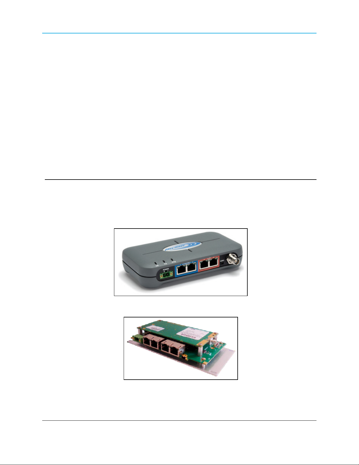
Thank you for purchasing the FreeWave Technologies, Inc. HT-P and HT-PE device.
The HT-P and HT-PE offers industrial serial and Ethernet wireless connectivity using the licensefree 900MHz spectrum for data communication over long distances.
HT-PE Product Image
FGR2-P Board
LUM0043AARev Jan-2015 Page 21 of 256
This document is the property of FreeWave Technologies, Inc. and contains proprietary information owned by
FreeWave®. This document cannot be reproduced in whole or in part by any means without written permission
from FreeWave Technologies, Inc.
Page 22

1. Introduction
The FGR2 Ethernet Radios and the HT Ethernet Radios:
l are NOT over-the-air compatible.
l do not link with each other.
l do not pass data to each other via RF.
An FGR2 Ethernet Radio can only interface with an HT Ethernet Radio through a hard-wired
Ethernet or serial connection.
l A Null Modem adapter and an M-to-M Gender Changer are required:
l for a serial-to-serial connection between an FGR2 Ethernet Radio and an HT Ethernet
Radio.
l between any PLUS Radio and a serial FreeWave Radio.
For an Ethernet-to-Ethernet connection, use a straight-through Ethernet cable because the
ports on the PLUS Radio are auto-crossover.
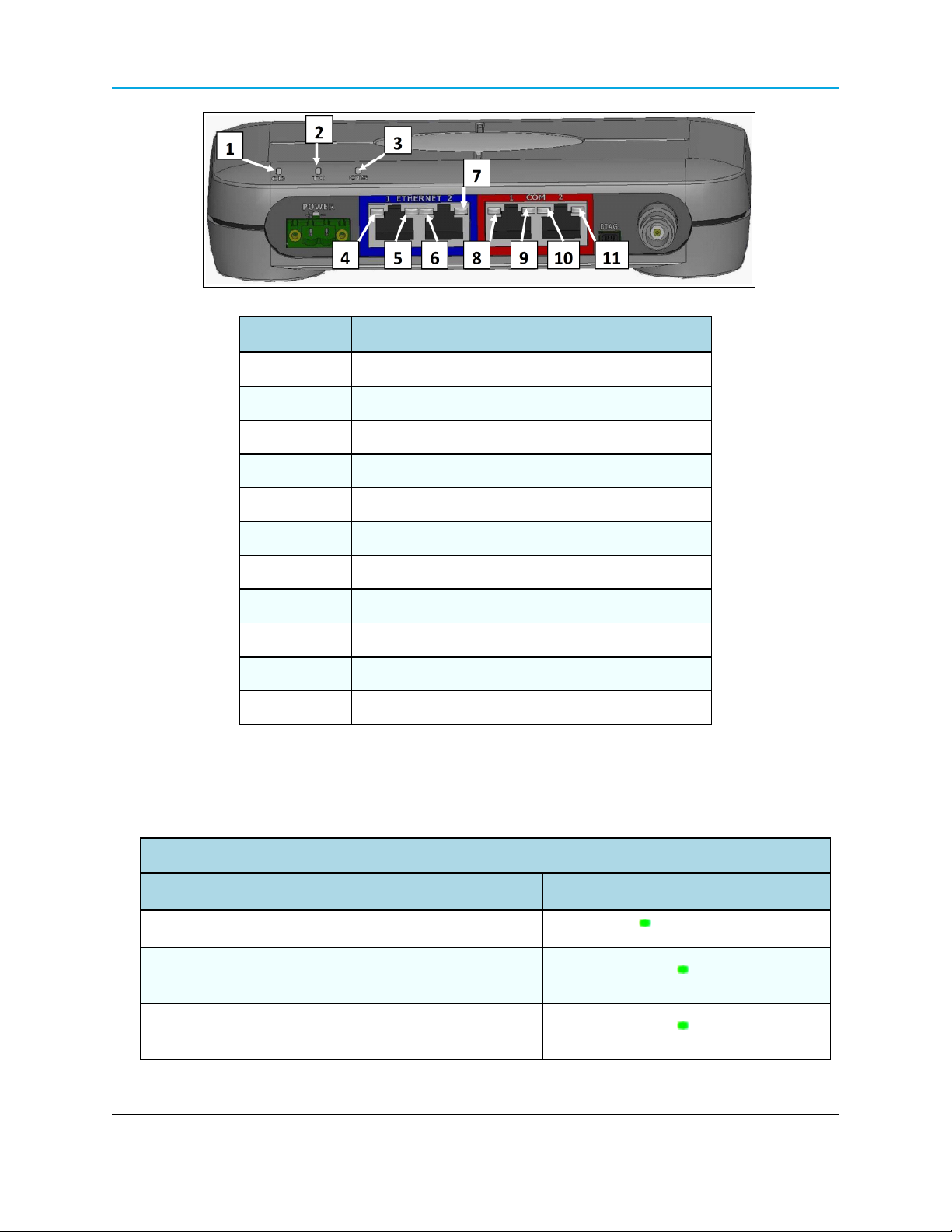
1.1 Components of the HT-P and HT-PE PLUS Radios
The HT-P and HT-PE PLUS Radios have these components:
l A power connector.
l LEDs to help determine when data is being received or sent from the radio and to provide
additional information about the radio's state.
l Two Ethernet ports (items 4 to 7, outlined in blue on the radio).
l Two COM ports (items 8 to 11, outlined in red on the radio).
l An antenna port.
l A diagnostic port (may be present on some units).
l The HT-P Radio has the same configuration as the HT-PE, without the enclosure.
Note: As of Jan-2015, the diagnostic port is not active.
No settings or diagnostics are delivered to this port.
Important!: All PLUS Radios MUST be configured using Ethernet, either through the
Configuration Windows or using FreeWave Tool Suite.
For more information about the setup tools available, see Configuration Tool Options on page 38.
Radios running software 2.26 or later can be configured using a terminal emulator
connected to COM1.
Page 22 of 256 LUM0043AA Rev Jan-2015
This document is the property of FreeWave Technologies, Inc. and contains proprietary information owned by
FreeWave®. This document cannot be reproduced in whole or in part by any means without written permission
from FreeWave Technologies, Inc.
Page 23
HT-P and HT-PE PLUS Radios: User Manual and Reference Guide
Label # Description
1 CD
2 TX
3 CTS
4 Ethernet 1 10 BaseT Link/Activity
5 Ethernet 1 100 BaseT Link
6 Ethernet 2 10 BaseT Link/Activity
7 Ethernet 2 100 BaseT Link
8 COM 1 Data (C1)
9 Error 1 (E1)
10 COM 2 Data (C2)
11 Error 2 (E2)
1.2 LED Designations
1.2.1 Authentication LEDs
Authentication LEDs
Condition LED Pattern
Endpoint cannot contact RADIUS server
Endpoint was denied authentication from the RADIUS
server
Solid green E1 LED
Alternating green E1 and E2 LED
Endpoint AES encryption key does not matchGateway
encryption key
LUM0043AA Rev Jan-2015 Page 23 of 256
This document is the property of FreeWave Technologies, Inc. and contains proprietary information owned by
FreeWave®. This document cannot be reproduced in whole or in part by any means without written permission
from FreeWave Technologies, Inc.
Alternating green E1 and E2 LED
Page 24
1. Introduction
1.2.2 Boot-Up LED Sequence
The LEDs on the HT-P and HT-PE PLUS Radio follows this sequence when the radio powers up:
C1 lights solid green .
1.
C2 lights solid green , C1 remains lit.
2.
E2 lights solid green , C1 and C2 remain lit.
3.
4. C1 turns off.
5. C2 turns off.
6. E2 turns off.
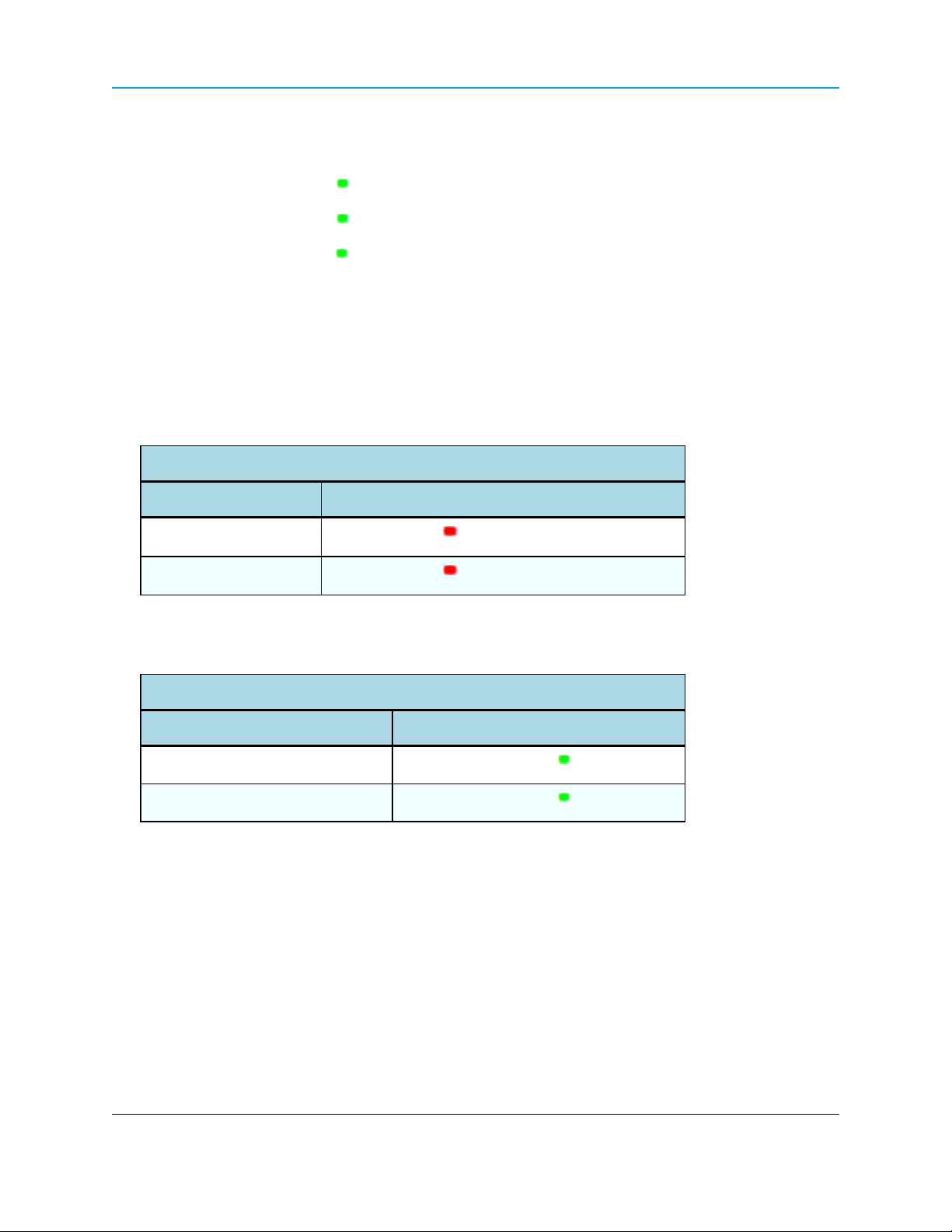
1.2.3 COM Port LED Conditions
COM Port LED Conditions
Condition Communications Port 1 (C1) or 2 (C2)
Data streaming into RX
Data streaming out TX
Solid red bright
Solid red bright
1.2.4 Error LED Conditions
Error LED Conditions
Condition Error Light (E1/E2)
Buffer overflow locally
Buffer overflow in network
E1 LED is solid green
E2 LED is solid green
Page 24 of 256 LUM0043AA Rev Jan-2015
This document is the property of FreeWave Technologies, Inc. and contains proprietary information owned by
FreeWave®. This document cannot be reproduced in whole or in part by any means without written permission
from FreeWave Technologies, Inc.
Page 25

HT-P and HT-PE PLUS Radios: User Manual and Reference Guide
1.2.5 Ethernet Port LED Conditions
Ethernet Port LED Conditions
Status 10 Base T Link/Activity 100 Base T Link LED
Solid green
Linked, data activity
Linked, no data activity
Not linked.
Blinking / Flickering green
(100 BaseT /Off (10 BaseT )
Solid green
Solid green
(100 BaseT /Off (10 BaseT )
Verify cable is in good
condition and plugged in.
Off Off
LUM0043AA Rev Jan-2015 Page 25 of 256
This document is the property of FreeWave Technologies, Inc. and contains proprietary information owned by
FreeWave®. This document cannot be reproduced in whole or in part by any means without written permission
from FreeWave Technologies, Inc.
Page 26
1. Introduction
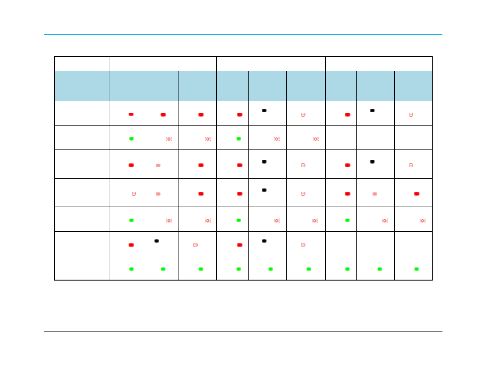
1.2.6 Point-to-Point (PTP) Operation LEDs
Gateway Endpoint Repeater
Condition
Powered, no link
Linked, no Repeater,
sending sparse data
Gateway calling
Endpoint through
Repeater
Gateway linked to
Repeater, not to
Endpoint
Repeater linked to
Endpoint
Mode 6 - waiting for
ATD command
Carrier
Detect
(CD)
Solid red
bright
Solid
green
Solid red
bright
Flashing
orange
Solid
green
Solid red
bright
Transmit
(Tx)
Solid red
bright
Intermittent
flash red
Solid red
dim
Solid red
dim
Intermittent
flash red
Off
Clear to
Send
(CTS)
Solid red
bright
Intermittent
flash red
Solid red
bright
Solid red
bright
Intermittent
flash red
Blinking
red
Carrier
Detect
(CD)
Solid red
bright
Solid
green
Solid red
bright
Solid red
bright
Solid
green
Solid red
bright
Transmit
(Tx)
Off
Intermittent
flash red
Off
Off
Intermittent
flash red
Off
Clear to
Send
(CTS)
Blinking
red
Intermittent
flash red
Blinking
red
Blinking
red
Intermittent
flash red
Blinking
red
Carrier
Detect
(CD)
Solid red
bright
n/a n/a n/a
Solid red
bright
Solid Red
bright
Solid
green
n/a n/a n/a
Transmit
(Tx)
Off
Off
Solid red
dim
Intermittent
flash red
Blinking
red
Blinking
red
Solid red
bright
Intermittent
flash red
Clear to
Send
(CTS)
Setup Mode
Solid
green
Solid
green
Solid
green
Solid
green
Solid
green
Solid
green
Solid
green
Solid
green
Solid
green
Page 26 of 256 LUM0043AA Rev Jan-2015
This document is the property of FreeWave Technologies, Inc. and contains proprietary information owned by FreeWave®. This document cannot be
reproduced in whole or in part by any means without written permission from FreeWave Technologies, Inc.
Page 27

1.2.7 Point-to-MultiPoint (PTMP) Operation LEDs
Gateway Endpoint Repeater
HT-P and HT-PE PLUS Radios
Condition
Powered, not linked
Repeater and Endpoint
linked to Gateway, no data
Repeater and Endpoint
linked to Gateway,
Gateway sending data to
Endpoint
Repeater and Endpoint
linked to Gateway,
Endpoint sending data to
Gateway
Gateway with diagnostics
program running
Carrier
Detect
(CD)
Solid red
bright
Solid red
bright
Solid red
bright
Solid green
RCV data
or Solid red
bright
Solid red
bright
Transmit
(Tx)
Solid red
dim
Solid red
dim
Solid red
dim
Solid red
dim
Solid red
dim
Clear to
Send
(CTS)
Off
Off
Off
Intermittent
flash red
Intermittent
flash red
Carrier
Detect
(CD)
Solid red
bright
Solid
green
Solid
green
Solid
green
Solid
green
Transmit
(Tx)
Off
Off
Off
Intermittent
flash red
Intermittent
flash red
Clear to
Send
(CTS)
Blinking
red
Solid red
bright
Solid red
bright
Solid red
bright
Solid red
bright
Carrier
Detect
(CD)
Solid red
bright
Solid
green
Solid
green
Solid
green
Solid
green
Transmit
(Tx)
Off
Solid red
dim
Solid red
dim
Solid red
bright
Solid red
bright
Clear to
Send
(CTS)
Blinking
red
Solid red
bright
Solid red
bright
Solid red
bright
Solid red
bright
* in an idle condition, the CTS LED is solid red with a solid link, as the link weakens the CTS LED on the Repeater and Endpoint
begins to blink
LUM0043AA Rev Jan-2015 Page 27 of 256
This document is the property of FreeWave Technologies, Inc. and contains proprietary information owned by FreeWave®. This document cannot be
reproduced in whole or in part by any means without written permission from FreeWave Technologies, Inc.
Page 28

1. Introduction
1.3 Choose a Radio Location
Placement of the FreeWave radio may have a significant impact on its performance. The key to the
overall robustness of the radio link is the height of the antenna.
When using an external antenna, placement of that antenna is critical to a solid data link. Other
antennas in close proximity are a potential source of interference.
Use the Radio Statistics to help identify potential problems. In general, FreeWave units with a
higher antenna placement will have a better communication link.
In practice, the radio should be placed away from computers, telephones, answering machines,
and other similar devices. The cable included with the radio provides ample distance for placement
away from other equipment.
Note: FreeWave offers directional and Omni-directional antennas with cable lengths ranging from 3 to
200 feet.
An adjustment as little as 2 feet in antenna placement may resolve noise issues.
In extreme cases, (e.g., Cellular Telephone tower interference) the band pass filters that
FreeWave offers may reduce this out-of-bandnoise.
1.4 Choose Point-to-Point (PTP) or Point-to-MultiPoint (PTMP) Operation
PTP Network
l A PTP network functions best when the network consists of one Gateway and one
Endpoint radio.
l A maximum of four Repeaters can be added to extend the reach of the network.
Important!: Adding a Repeater to a network cuts the network throughput by 50%.
In a Point-to-Point network, the Gateway determines all settings in an Endpoint or Repeater,
except for the Transmit Power and Retry Timeout. All other settings in a Point-to-Point network
are determined by the Gateway's settings.
PTMP Network
In a PTMP network, the Gateway radio is able to simultaneously communicate with numerous
Endpoint radios.
l In its simplest form, a PTMP network functions with the Gateway broadcasting its
messages to all Endpoint radios.
Page 28 of 256 LUM0043AA Rev Jan-2015
This document is the property of FreeWave Technologies, Inc. and contains proprietary information owned by
FreeWave®. This document cannot be reproduced in whole or in part by any means without written permission
from FreeWave Technologies, Inc.
Page 29

HT-P and HT-PE PLUS Radios: User Manual and Reference Guide
l If requested by the Gateway, the Endpoint radios respond to the Gateway when given data
by the device connected to the data port.
l This response depends on the setup.
l The network can be extended with as many Repeaters as is required.
Important!: Adding a Repeater to a network cuts the network throughput by 50%.
1.4.1 Differences between PTP and PTMP Networks
PTP Network
In a PTP network all packets are acknowledged, whether sent from the Gateway to the Endpoint or
from the Endpoint to the Gateway.
PTMP Network
In a PTMP network, the user determines the number of times outbound packets from the Gateway
or Repeater to the Endpoint or other Repeaters are sent.
l The receiving radio, Endpoint or Repeater, accepts the first packet received that passes
the 32 bit CRC.
l However, the packet is not acknowledged.
l On the return to the Gateway, all packets sent are acknowledged or retransmitted until they
are acknowledged.
l Therefore, the return link in a PTMP network is generally very robust.
Traditionally, a PTMP network is used in applications where data is collected from many
instruments and reported back to one central site. The architecture of such a network is different
from PTP applications. These parameters influence the number of radios that can exist in a PTMP
network:
l Baud Rate. The data rate between the radio and the device it is connected to could limit
the amount of data and the number of radios that can exist in a network.
l Contention: The amount of contention between Endpoint radios. Polled Endpoint radios
versus vs. timed Endpoint radios.
l Data Block Size. The longer the data blocks, the fewer number of deployed Endpoint
radios can exist in the network.
l Repeater Use. Using the Repeater setting in a PTP or PTMP network decreases the
overall network capacity by at least 50%.
LUM0043AA Rev Jan-2015 Page 29 of 256
This document is the property of FreeWave Technologies, Inc. and contains proprietary information owned by
FreeWave®. This document cannot be reproduced in whole or in part by any means without written permission
from FreeWave Technologies, Inc.
Page 30

1. Introduction
Example: If the network polls once a day to retrieve sparse data, several hundred Endpoint
radios could be configured to a single Gateway.
However, if each Endpoint transmits larger amounts of data or data more frequently, fewer
Endpoint radios can link to the Gateway while receiving the same network performance.
When larger amounts of data are sent more frequently, the overall network bandwidth is closer
to capacity with fewer Endpoint radios.
Page 30 of 256 LUM0043AA Rev Jan-2015
This document is the property of FreeWave Technologies, Inc. and contains proprietary information owned by
FreeWave®. This document cannot be reproduced in whole or in part by any means without written permission
from FreeWave Technologies, Inc.
Page 31

HT-P and HT-PE PLUS Radios: User Manual and Reference Guide
2. Set Up and Program Radios
This section provides details about setup, programming, and defining who has access to the HT-P
and HT-PE PLUS Radios using the available setup tools. This information is included:
l How to determine and set the IP addresses of the radios to program.
l The IP address of the radio is needed before reading the current settings or sending
new settings to the radio.
l An introduction to the available basic programming tools and their parameters.
l How to define permissions using user accounts and group levels that grant access to the
radio and its settings.
l How to upgrade the software version running on the radio.
2.1 Basic Steps to Programming the HT-P and HT-PE PLUS Radios
This basic procedure programs any FreeWave PLUS Radio.
Procedure
1. Determine or set the radio's IP address.
Note: The PLUS radio can be programmed using the terminal menu available through the radio's
serial port without having to know the radio's IP address.
2. Be familiar with the network and know if it is a Point-to-Point (PTP) or Point-to-MultiPoint
(PTMP) configuration.
LUM0043AARev Jan-2015 Page 31 of 256
This document is the property of FreeWave Technologies, Inc. and contains proprietary information owned by
FreeWave®. This document cannot be reproduced in whole or in part by any means without written permission
from FreeWave Technologies, Inc.
Page 32

2. Set Up and Program Radios
Note: Most FreeWave networks are PTMP.
3. Connect the radio to the configuration tool, such as Tool Suite or view the radio's
Configuration Windows.
4. If using Tool Suite, verify the computer running Tool Suite has an IP address where the
first three octets are the same as the radio to connect to.
5. Set the radio's operation mode (e.g., Gateway, Repeater, or Endpoint).
6. Set the radio's network type (PTP or PTMP).
7. Program the radio, verifying all devices in a PTMP network have the same settings for
these parameters:
l Frequency Key
l Max Packet Size
l Min Packet Size
l Network ID
l RF Data Rate
8. Setup the Call Book if the radio is in a network NOT using Network IDs.
See About the Call Book on page 132.
FreeWave Recommends: While the Call Book is an option in Point-to-MultiPoint networks,
FreeWave strongly recommends using the Network ID feature in most applications.
If a large MultiPoint network is implemented using the Call Book and a radio needs to be added or
replaced in the network, each radio MUST be physically reprogrammed in the network and the new
serial number entered in the radio's Call Book.
This can be a time consuming process and can cause a delay in getting the network back up and
running.
Note: If using a Network ID, see the Network ID and Subnet ID parameters described in the Radio
Settings on page 109.
2.1.1 PTMP Network Considerations
Planning is important when installing PTMP networks. A PTMP network requires that several
parameters are set consistently on ALL radios in the network. This includes:
l Frequency Key.
l Min and Max Packet Size.
l Network ID.
l RF Data Rate.
Page 32 of 256 LUM0043AA Rev Jan-2015
This document is the property of FreeWave Technologies, Inc. and contains proprietary information owned by
FreeWave®. This document cannot be reproduced in whole or in part by any means without written permission
from FreeWave Technologies, Inc.
Page 33

HT-P and HT-PE PLUS Radios: User Manual and Reference Guide
Important!: If several independent, PTMP networks are located in close proximity, it is very important
to include as much frequency and time diversity as possible using different Frequency Key and Min
and Max Packet Sizes.
2.2 Powering the HT-P and HT-PE PLUS Radio
Connect the HT-P and HT-PE PLUS Radio to a positive DC power supply with +7 to +30 VDC
(typically, +12 VDC).
The power supply used MUST provide more current than the amount of current drain listed on the
HT-P and HT-PE Technical Specifications on page 191 for the voltage used.
Example: When using +12 VDC, the power supply must provide current capability greater than the
drain that is required for transmit or greater than 550 mA.
Note: For any application where the radio is used in a UL-controlled environment, the power supply
MUST be a Class 2 power source. Using a dedicated power supply line is preferred.
Warning! If the power supply is above approximately +18 to +20 VDC, use a 1 ohm resistor in
line with B+ input to the radio.
Warning! If the power supply line runs outside the enclosure, use electrostatic discharge
(ESD) protectors to protect the radio from electric shock and transient voltage suppressors
(TVS) to protect from an over-voltage situation.
Using both helps to ensure long-term, reliable operation.
2.3 Identify and Change the HT-P and HT-PE PLUS Radios's IP Address
Note: In software versions 2.26 and later, the HT-P and HT-PE PLUS radio can be programmed
through the radio's COM1 port without having to know the radio's IP address.
It is good practice to identify the IP addresses of all the devices in the network and verify each
is unique.
l The HT-P and HT-PE PLUS Radio's default IP address is 192.168.111.100.
l The default password is admin.
If the address has changed, is unknown, or needs a change to the address, use one of these tools:
LUM0043AA Rev Jan-2015 Page 33 of 256
This document is the property of FreeWave Technologies, Inc. and contains proprietary information owned by
FreeWave®. This document cannot be reproduced in whole or in part by any means without written permission
from FreeWave Technologies, Inc.
Page 34

2. Set Up and Program Radios
l Tool Suite with the radio's Discovery Server.
l A terminal emulator (e.g., Tera Term, HyperTerminal), using the COM1 serial port on the
radio.
Important!: Each radio in the network MUST have its own unique IP address.
Putting multiple devices with the same IP address on the same network can cause network problems.
2.3.1 Using a Terminal Emulator
Use a terminal emulator (e.g., Tera Term, HyperTerminal) to access the terminal menu.
For any terminal emulator application:
1. Plug the serial cable into COM1 on the radio.
2. With the radio disconnected from power, open a session.
3. Verify these are the port settings for a proper connection to the radio:
Port Setting Select
Bits per second 19200
Data Bits 8
Parity None
Stop Bits 1
Flow Control None
Note: By default, Setup Terminal contains the Port Settings.
For more information about using Tool Suite, see the Tool Suite User Manual available by selecting
File > Help in the Tool Suite software or download the latest version from www.freewave.com.
Procedure
This procedure describes how to access the radio's terminal menu through the serial port using the
Setup Terminal application in Tool Suite.
Important!: The connected cable MUST have RTS and CTS connected to enable setup through
COM1.
In addition, the terminal program software MUST take the RTS line on the radio’s serial port HIGH.
1. Plug a serial cable into COM1 and connect it to the computer running Tool Suite.
2. With the radio disconnected from power, open Tool Suite.
3. On the Applications pane, click Setup Terminal.
Page 34 of 256 LUM0043AA Rev Jan-2015
This document is the property of FreeWave Technologies, Inc. and contains proprietary information owned by
FreeWave®. This document cannot be reproduced in whole or in part by any means without written permission
from FreeWave Technologies, Inc.
Page 35

HT-P and HT-PE PLUS Radios: User Manual and Reference Guide
4. Click the Connections list box arrow and select the COM port the radio is connected to.
Connections list box
5. With the radio still disconnected from power, click Connect.
6. Connect power to the radio.
After a few seconds, a confirmation message appears:
Confirmation message
7. Type a Y to access the terminal setup of the radio.
After entering a Y, the radio's a Login prompt appears showing the model, serial number,
software, and wireless versions.
Important!: Any other key exits, allowing the radio to complete the boot-up.
8. Enter the Administrator Login name and Password.
Note: The FreeWave factory default password is admin for both.
Need correct screenshot here.
9. Enter the IP Setup menu number (i.e., 1) and press <Enter>.
The IP Menu appears showing the IP address and other IP setup options.
LUM0043AA Rev Jan-2015 Page 35 of 256
This document is the property of FreeWave Technologies, Inc. and contains proprietary information owned by
FreeWave®. This document cannot be reproduced in whole or in part by any means without written permission
from FreeWave Technologies, Inc.
Page 36

2. Set Up and Program Radios
The radio's current IP address appears in the IP Address field.
IP Menu in Tool Suite terminal emulator
10. Enter the number of the selection and make the applicable changes.
Example: Enter 2 and press <Enter> to change the Default Gateway.
Note: Each setting is described in detail in the next chapter.
11. Press <Esc> to exit the Setup menu to reboot the radio.
2.3.2 Using Discovery Server to Determine a Radio's IP Address
Use the FreeWave Discovery Server free utility to determine and set the IP address of a HT-P
and HT-PE PLUS Radio with a software version of 2.8 or higher.
Note: Discovery Server is available for download from www.freewave.com.
FreeWave Recommends: Firewall software (e.g., Windows® Firewall and McAfee Personal
Firewall) can prevent the Discovery Server from operating properly.
FreeWave recommends disabling any firewall software prior to running Discovery Server.
Page 36 of 256 LUM0043AA Rev Jan-2015
This document is the property of FreeWave Technologies, Inc. and contains proprietary information owned by
FreeWave®. This document cannot be reproduced in whole or in part by any means without written permission
from FreeWave Technologies, Inc.
Page 37

HT-P and HT-PE PLUS Radios: User Manual and Reference Guide
Note: See Using the Discovery Server on page 231 for more information.
Procedure
1. Open Discovery Server.
Discovery Server automatically attempts to discover any HT-P and HT-PE PLUS Radios
connected via Ethernet. The radios broadcast this information, so they should be
successfully discovered if they have a physical Ethernet connection to the network or are
able to communicate back through their Gateway.
Note: In software versions 2.22 and later, Endpoints and MultiPoint Repeaters can only be discovered
if the computer running Discovery Server is connected on the Gateway side of the network.
If connected to an Endpoint or MultiPoint Repeater in this situation, only that radio and the Gateway are
reported.
2.3.3 Set the Radio's IP Address using Discovery Server
1. Open Discovery Server.
2. Right-click the radio in the list to change and click Change Basic Settings.
3. In the IP Address text box, update the IP address to the address to assign to the radio.
4. In the Password text box, enter the current administrator password.
Important!: Radios running software version 2.22 or earlier ONLY accept admin as the valid
password.
Radios running a later version of software accept any password with a maximum of seven (7)
LUM0043AA Rev Jan-2015 Page 37 of 256
This document is the property of FreeWave Technologies, Inc. and contains proprietary information owned by
FreeWave®. This document cannot be reproduced in whole or in part by any means without written permission
from FreeWave Technologies, Inc.
Page 38

2. Set Up and Program Radios
characters.
5. Click Change to change the settings on the radio.
Note: Discovery Server does NOT accept passwords longer than seven (7) characters.
Discovery Server can only reboot a radio if that radio's administrator password is seven (7) characters
or less.
Use this password limitation to limit the radios that can be changed using the Discovery
Server application.
2.4 Configuration Tool Options
After the Ethernet address is identified and changed on the HT-P and HT-PE PLUS radio, use
these setup tools to configure the radio:
l Tool Suite - Tool Suite is a FreeWave configuration software application and is the
recommended method for programming the radios.
Tool Suite provides a group of tools for configuring the devices in the network and for
monitoring the network's performance. Tool Suite is available for download from
www.freewave.com.
To access the radio in Tool Suite, see Reading HT-P and HT-PE PLUS Radios in Tool
Suite on page 42.
Note: For more information about using Tool Suite, see the Tool Suite User Manual available
by selecting File > Help in the Tool Suite software or download the latest version from
www.freewave.com.
l Configuration Windows - Each PLUS Radio has built in Configuration windows used to
program its settings.
A Web browser must be installed on the computer to access the Configuration Windows.
Note: See Accessing Configuration Windows on page 42.
l Terminal Interface - Program a PLUS Radio through its serial port using the menus
through a terminal emulator (e.g., Tera Term, HyperTerminal) or the Setup Terminal in
Tool Suite.
Note: For more information, see Using a Terminal Emulator on page 34.
The parameters and statistics on a HT-P and HT-PE PLUS Radio are grouped into categories. The
tabs in Tool Suite mirror the Configuration Windows and terminal interface menu options.
Page 38 of 256 LUM0043AA Rev Jan-2015
This document is the property of FreeWave Technologies, Inc. and contains proprietary information owned by
FreeWave®. This document cannot be reproduced in whole or in part by any means without written permission
from FreeWave Technologies, Inc.
Page 39

HT-P and HT-PE PLUS Radios: User Manual and Reference Guide
Need new composite image here.....
Composite of the tab, window, and menu options
Each tab, window, and menu contains parameters that apply to the same area of functionality.
Example: To setup a serial port, access all the parameters for the first serial port in the Serial Setup 1
window.
LUM0043AA Rev Jan-2015 Page 39 of 256
This document is the property of FreeWave Technologies, Inc. and contains proprietary information owned by
FreeWave®. This document cannot be reproduced in whole or in part by any means without written permission
from FreeWave Technologies, Inc.
Page 40

2. Set Up and Program Radios
Tool Suite windows
Window Used To
View all device status information.
Status
Note: See Viewing Radio Status and Statistics on page 165.
Use to identify and configure the IP address, Subnet Mask, and Default
Gateway.
IP Setup
Serial Setup 1
Serial Setup 2
Radio Setup
Important!: Check with the Network Administrator before changing
these settings.
Note: See IP and Network Communication Settings on page 71.
Use to identify and configure the port numbers and data settings for each
serial port.
Important!: These settings MUST match the device to which each
port is connected.
Note: See Serial Port Settings on page 85.
Use to identify and configure the radio’s:
l Operation Mode.
l Transmission Characteristics.
l MultiPoint Parameters.
l Call Book.
Note: See Radio Settings on page 109.
Use to identify and configure the:
l RADIUS server authentication.
Security
l MAC filtering.
l AES Encryption information.
Note: See Security Settings on page 139.
Page 40 of 256 LUM0043AA Rev Jan-2015
This document is the property of FreeWave Technologies, Inc. and contains proprietary information owned by
FreeWave®. This document cannot be reproduced in whole or in part by any means without written permission
from FreeWave Technologies, Inc.
Page 41

HT-P and HT-PE PLUS Radios: User Manual and Reference Guide
Tool Suite windows
Window Used To
Use to identify and configure the SNMP management features of the radio.
l The radio supports SNMP versions 1, 2, and 3.
l All of the SNMP-manageable objects for FreeWave's radios are
SNMP
Diagnostics
contained in a single MIB file: Object List for FREEWAVE-
TECHNOLOGIES-MIB on page 237.
Note: This file is available from FreeWave upon request.
See SNMP Settings on page 151.
Use to view this information:
l Signal level
l Noise level
l Signal-to-noise delta
l Receive rate for each frequency available to the radio.
Note: See Viewing Radio Status and Statistics on page 165.
Use to add or change logins for the radio.
l A maximum of nine (9) custom users can be created for each radio.
Users
l The admin user is the permanent 10th user.
Note: See Creating User Logins on page 53.
Use to edit the site information and upgrade the radio’s Software.
Tools
Note: In a MultiPoint Gateway, use to enable the Global Change
functionality.
Note: The descriptions and procedures in this manual are referenced as they appear in Tool Suite.
If functionality is available only through the Configuration Windows or the terminal menu, or is different
than Tool Suite, the information is provided as it appears in those tools.
The specific Configuration window or terminal menu is identified that must be used.
Each parameter described in this manual also contains the path to the menu option in the terminal
interface.
Use Discovery Server to define a PLUS Radio's IP setup parameters, such as its IPaddress,
Subnet Mask, default gateway, and VLAN information.
For information about using the Discovery Server, see Using the Discovery Server on page
231.
LUM0043AA Rev Jan-2015 Page 41 of 256
This document is the property of FreeWave Technologies, Inc. and contains proprietary information owned by
FreeWave®. This document cannot be reproduced in whole or in part by any means without written permission
from FreeWave Technologies, Inc.
Page 42

2. Set Up and Program Radios
2.5 Reading HT-P and HT-PE PLUS Radios in Tool Suite
The radio's IP address must be known prior to reading a radio's settings and programming a radio
using Tool Suite.
Note: See Identify and Change the HT-P and HT-PE PLUS Radios's IP Address on page 33.
Important!: The computer running Tool Suite must have an IPaddress within the same subnet as the
radio.
If the Subnet Mask for the network is 255.255.255.0, the first three octets, or sections, of the IP
address on the radio and the IP address on the computer MUST match. The last octet is unique.
Example: If the subnet mask is 255.255.255.0 and the radio's IP address is 198.168.111.100, then the
computer running Tool Suite must have an IP address that begins with 198.168.111.
The last section of the IP address is unique to identify the device.
Note: For more information about using Tool Suite, see the Tool Suite User Manual available by
selecting File > Help in the Tool Suite software or download the latest version from
www.freewave.com.
Procedure
1. Open Tool Suite.
2. Open the Configuration window.
3. Select or create an Ethernet network.
4. Enter the radio's IP address in the IP Address text box in the upper left corner of the Plus
Configuration ribbon.
5. Click Read Radio in the Plus Configuration ribbon.
Tool Suite connects to the radio and shows the Discovered Devices.
6. In the Discovered Devices, click the radio to view its current settings in the tabs.
2.6 Accessing Configuration Windows
Each HT-P and HT-PE PLUS Radio includes Configuration windows to identify, change, and
program its settings.
l A Web browser must be installed on the computer to access the Configuration windows.
l The router/switch and/or the computer accessing the radio must be on the same subnet.
If the Subnet Mask for the network is 255.255.255.0, the first three octets, or sections, of the IP
address on the radio and the IP address on the computer MUST match. The last octet is unique.
Page 42 of 256 LUM0043AA Rev Jan-2015
This document is the property of FreeWave Technologies, Inc. and contains proprietary information owned by
FreeWave®. This document cannot be reproduced in whole or in part by any means without written permission
from FreeWave Technologies, Inc.
Page 43

HT-P and HT-PE PLUS Radios: User Manual and Reference Guide
Example: If the subnet mask is 255.255.255.0 and the radio's IP address is 198.168.111.100, then the
computer running Tool Suite must have an IP address that begins with 198.168.111.
The last section of the IP address is unique to identify the device.
Administrator Login and Password
l The default User Name for the administrator login is admin.
l The default Password is admin.
Note: The administrator login has full permission to change all settings on the radio,
including upgrading software.
Guest Login and Password
l The default User Name for the guest login is guest.
l The default Password is guest.
l The guest login can view the settings but CANNOT:
l save any changes.
l view the Security window on page 205
l view the Tools window on page 219.
l reboot the radio.
Note: The button is not available to Guest users.
Procedure
1. Plug the radio into either a computer or a switch/router using an RJ45 cable.
2. Open a Web browser window.
3. Enter the IP address of the radio into the address bar.
Example: Enter http://192.168.111.100 in the address bar of the web browser to access a
radio with that IP address.
Note: The default IP address set at the factory is 192.168.111.100.
4. Refresh the browser window.
The Authentication Required dialog box opens.
5. Enter the User Name and Password to access the radio.
LUM0043AA Rev Jan-2015 Page 43 of 256
This document is the property of FreeWave Technologies, Inc. and contains proprietary information owned by
FreeWave®. This document cannot be reproduced in whole or in part by any means without written permission
from FreeWave Technologies, Inc.
Page 44

2. Set Up and Program Radios
6. Click OK.
The Status window opens.
Authentication Required dialog box
Page 44 of 256 LUM0043AA Rev Jan-2015
This document is the property of FreeWave Technologies, Inc. and contains proprietary information owned by
FreeWave®. This document cannot be reproduced in whole or in part by any means without written permission
from FreeWave Technologies, Inc.
Page 45

HT-P and HT-PE PLUS Radios: User Manual and Reference Guide
Status window
2.7 Navigating the Configuration Windows
2.7.1 Menu bar
The Configuration Windows group the parameters into the Menu bar on the left side of all windows.
LUM0043AA Rev Jan-2015 Page 45 of 256
This document is the property of FreeWave Technologies, Inc. and contains proprietary information owned by
FreeWave®. This document cannot be reproduced in whole or in part by any means without written permission
from FreeWave Technologies, Inc.
Page 46

2. Set Up and Program Radios
Menu bar
l Click any item in the Menu bar to open that Configuration window.
l The currently selected window is highlighted in the Menu bar.
2.7.2 Save and Apply
When making changes to the radio settings, click the button before
l
navigating away from a window or rebooting the radio to save the changes.
Important!: No changes take effect until you click .
Note: If there is no button, the changes take effect immediately.
l When the changes have been successfully saved and applied, the Change Succeeded
message appears under the button.
Change Succeeded message
Page 46 of 256 LUM0043AA Rev Jan-2015
This document is the property of FreeWave Technologies, Inc. and contains proprietary information owned by
FreeWave®. This document cannot be reproduced in whole or in part by any means without written permission
from FreeWave Technologies, Inc.
Page 47

HT-P and HT-PE PLUS Radios: User Manual and Reference Guide
l Any change made in the Configuration Windows that is not yet saved is highlighted in
yellow.
This highlight indicates that you need to click before navigating away from
the page, or the changes will be lost.
Changed Baud Rate before is clicked.
l Some setting changes (e.g., changes to the IP Setup) require a reboot to complete the
changes.
When such a change is made, the Change Succeeded message below the
l
button changes to include a link labeled Reboot Required.
2.7.3 Reboot
Note: The button is not available to Guest users.
Below the Menu bar is the button.
l
Click this button to force the radio to reboot.
Click either the Reboot Required link or the button to reboot the radio and
l
apply the requested changes.
Important!: The requested changes are NOT made until the radio is rebooted.
Note: A Reboot Required link appears at the top of every page until the radio is rebooted.
LUM0043AA Rev Jan-2015 Page 47 of 256
This document is the property of FreeWave Technologies, Inc. and contains proprietary information owned by
FreeWave®. This document cannot be reproduced in whole or in part by any means without written permission
from FreeWave Technologies, Inc.
Page 48

2. Set Up and Program Radios
Reboot Required message
2.8 Accessing the Terminal Menu
Each HT-P and HT-PE PLUS Radio has a built in terminal menu used to program its settings.
Access the menu using a terminal emulator (e.g., HyperTerminal, Tera Term).
Note: For access information, see the instructions in Using a Terminal Emulator on page 34.
2.9 Navigating the Terminal Menu
When logging in to the HT-P and HT-PE PLUS radio's terminal menu, the main menu appears. All
the radio's configuration parameters are grouped into categories in the Main Menu.
To select a menu option, enter the letter or number at the cursor prompt at the bottom of the screen.
The options in that menu appear.
FreeWave HyperTerminal window
Page 48 of 256 LUM0043AA Rev Jan-2015
This document is the property of FreeWave Technologies, Inc. and contains proprietary information owned by
FreeWave®. This document cannot be reproduced in whole or in part by any means without written permission
from FreeWave Technologies, Inc.
Page 49

HT-P and HT-PE PLUS Radios: User Manual and Reference Guide
l Each submenu has its own options.
l Enter the number or letter that precedes the selection at the prompt to set any parameter.
l A second prompt may appear to enter the new value.
Example: If 4 is entered, the Radio Setup menu appears.
HyperTerminal Radio Setup window
Note: For parameters that have only two options, (e.g., Enabled or Disabled) entering the letter or
number of the option at the prompt toggles the selection to the other value.
Example: If the Repeaters setting in the Radio Setup menu is set to Enabled and you enter G at the
Radio Setup menu prompt, the value toggles to Disabled and the menu refreshes.
Important!: Parameter settings are only sent to the radio when Setup Mode is exited (press <Esc>
from the Setup Main menu).
Parameter settings are NOT sent to the radios when changes are made.
LUM0043AA Rev Jan-2015 Page 49 of 256
This document is the property of FreeWave Technologies, Inc. and contains proprietary information owned by
FreeWave®. This document cannot be reproduced in whole or in part by any means without written permission
from FreeWave Technologies, Inc.
Page 50

2. Set Up and Program Radios
2.10 Providing Site Information
For each radio in the network, information to help identify that HT-P and HT-PE PLUS radio (i.e.,
name and contact information) can be provided. The site information appears on the Status page
in the Configuration Windows.
2.10.1 Providing Site Information in Tool Suite
1. Open Tool Suite.
2. Connect to the radio.
Note: For more information, see Reading HT-P and HT-PE PLUS Radios in Tool Suite on page
42.
3. In the Applications bar, click Configuration.
The Configuration window opens.
4. On the ribbon, clickRead Radio to read the radio's current settings.
5. Click the Tools tab.
Important!: Free form text fields cannot CANNOT any of these characters: %, &, +, =, < or >.
6. In the Site Name text box, enter a maximum of 25 characters to help identify the radio.
7. In the Site Contact text box, enter a maximum of 25 characters about who to contact
about the site's status.
8. In the System Name text box, enter a maximum of 32 characters to identify the system the
radio operates in.
9. In the Notes text box, enter a maximum of 50 characters to describe the radio or the site.
10. Select a Tool Suite program option to send the changes to the radio.
Note: For more information about using Tool Suite, see the Tool Suite User Manual available by
selecting File > Help in the Tool Suite software or download the latest version from
www.freewave.com.
2.10.2 Providing Site Information using the Configuration Window
1. Follow the procedure for Accessing Configuration Windows on page 42.
The Status window opens.
2. On the Menu bar, click Tools.
The Tools window opens.
Page 50 of 256 LUM0043AA Rev Jan-2015
This document is the property of FreeWave Technologies, Inc. and contains proprietary information owned by
FreeWave®. This document cannot be reproduced in whole or in part by any means without written permission
from FreeWave Technologies, Inc.
Page 51

HT-P and HT-PE PLUS Radios: User Manual and Reference Guide
Tools window
3. In the Change Site Information area:
Important!: Free form text fields cannot CANNOT any of these characters: %, &, +, =, < or >.
a. In the Site Name text box, enter a maximum of 25 characters to help identify the
radio.
b. In the Site Contact text box, enter a maximum of 25 characters about who to
contact about the site's status.
c. In the System Name text box, enter a maximum of 32 characters to identify the
system the radio operates in.
d. In the Notes text box, enter a maximum of 50 characters to describe the radio or the
site.
Click to save the changes.
4.
2.11 Using the MultiPoint Gateway to Change All Connected Radios
Note: The Global Change function can only be enabled or disabled using the Configuration Web pages.
Often, the settings on radios in the network should be the same as the settings in the MultiPoint
Gateway. Instead of changing each radio individually, use the Global Change function to push the
LUM0043AA Rev Jan-2015 Page 51 of 256
This document is the property of FreeWave Technologies, Inc. and contains proprietary information owned by
FreeWave®. This document cannot be reproduced in whole or in part by any means without written permission
from FreeWave Technologies, Inc.
Page 52

2. Set Up and Program Radios
IP Setup, Radio Setup, Security, SNMP, and User settings to all connected radios in the
network.
1. Access the Gateway's Configuration Windows.
Note: See Accessing Configuration Windows on page 42.
2. On the Menu bar, click Tools.
The Tools window opens.
Tools window
Click .
3.
The button changes to DISABLE Global Change Functionality.
Note: Click that button to turn off global changing.
When enabled, the All Changes to All Radios message appears at the top of every page for
radios connected to the Gateway.
All Changes to All Radios message
l On the Gateway, the Push Globally button replaces the Save/Apply button on the
windows that allow global changes.
Page 52 of 256 LUM0043AA Rev Jan-2015
This document is the property of FreeWave Technologies, Inc. and contains proprietary information owned by
FreeWave®. This document cannot be reproduced in whole or in part by any means without written permission
from FreeWave Technologies, Inc.
Page 53

HT-P and HT-PE PLUS Radios: User Manual and Reference Guide
l Click Push Globally to send any changes made to the parameters on that window
are sent to all the connected radios.
l Every connected radio that receives the changes reboots after the changes are
applied.
l The Configuration Windows on the remote radios are not accessible until the reboot
completes.
Note: The settings on the MultiPoint Gateway are NOT changed during a global change.
When the Global Change functionality is enabled, these changes occur to these windows :
l IP Setup window - The IP Address text box is hidden.
It cannot be part of a global change.
l Radio Setup window - The Network Type and Modem Mode list boxes are hidden.
They do NOT change as part of a global change.
Important!: Changes made to the settings on the Radio Setup window can cause the radios to
lose communication with the Gateway and/or MultiPoint Repeaters.
Use caution when making global changes.
l Security window - All settings on the Security window can be part of a global change.
Caution: When changing the AES Encryption Key globally, make the first change on
the MultiPoint Gateway.
After the Gateway has been changed, push the new key to the other radios in the
network.
If this is not done in this order, changing the encryption key can cause radios to lose
connectivity with the Gateway for an extended period of time.
l SNMP window - All settings on the SNMP window can be part of a global change.
l Users window - The Edit Group Level Rights area and the User Accounts Level can
be adjusted using global changes.
Important!: User accounts and User passwords CANNOT be created or deleted using global
changes.
2.12 Creating User Logins
To limit who can access the HT-P and HT-PE PLUS Radios in the network and edit configuration
settings, a maximum of nine (9) custom users with login access can be created.
Note: The permanent admin login is the 10th login.
LUM0043AA Rev Jan-2015 Page 53 of 256
This document is the property of FreeWave Technologies, Inc. and contains proprietary information owned by
FreeWave®. This document cannot be reproduced in whole or in part by any means without written permission
from FreeWave Technologies, Inc.
Page 54

2. Set Up and Program Radios
Procedure
1. Defining User Groups on page 54.
2. Editing User Group Rights on page 54.
3. Adding and Deleting Users on page 55.
4. Changing User Passwords on page 57.
2.12.1 Defining User Groups
User groups set the access rights for each Tool Suite tab or Configuration Windows for a radio.
Users are assigned to a group and inherit the access rights that are set for that group.
A maximum of three groups (Groups 1, 2, and 3) can be created. In each group, assign one access
level to each page or tab:
l No Access - Users cannot see the settings in the tab or page.
l Any attempt to navigate to the tab or page shows an Access Denied message.
l Read Only - Users can see the settings in the tab or page, but cannot save or apply any
changes.
l Full Access - Users are able to see the settings in the tab or page and can save and apply
changes.
When a user is created it is assigned to a group. The group number corresponds to the user group
and the user inherits the permissions assigned to that group.
Example: If Group 1 has Read Only access to the IP Setup parameters and No Access to the
Security parameters, any user assigned to Group 1 can view IP Setup parameters but not make
changes, and receives an Access Denied message if they try to access the Security tab or page.
Note: You cannot change the group assigned to the admin user. The admin user always has Full
Access to all pages.
2.12.2 Editing User Group Rights
Use Tool Suite to Edit User Group Rights
1. Access the radio's settings in Tool Suite.
Note: For more information, see Reading HT-P and HT-PE PLUS Radios in Tool Suite on page
42.
2. Click the Users tab to view the User settings.
3. For each level, select the access rights for each group of parameters.
Page 54 of 256 LUM0043AA Rev Jan-2015
This document is the property of FreeWave Technologies, Inc. and contains proprietary information owned by
FreeWave®. This document cannot be reproduced in whole or in part by any means without written permission
from FreeWave Technologies, Inc.
Page 55

HT-P and HT-PE PLUS Radios: User Manual and Reference Guide
Example: The Level 1 Account IP Setup field represents Group 1's access rights to the IP Setup
page or tab.
Changes are saved automatically when they're made.
Important!: Be sure to apply them to the radio.
Use the Configuration Windows to Edit User Group Rights
1. Follow the procedure for Accessing Configuration Windows on page 42.
The Status window opens.
2. On the Menu bar, click Users.
The Users window opens.
Users windows
3. In the Edit Group Level Rights area, click the list box arrow for each group and select the
access rights for each window.
Click to save the changes and apply them to the radio.
4.
2.12.3 Adding and Deleting Users
A maximum of nine (9) custom users with login access can be created to limit who can access the
HT-P and HT-PE PLUS Radios in the network and edit configuration settings.
Important!: Users can only be created and edited using the Configuration Windows.
Note: The permanent admin login is the 10th login.
LUM0043AA Rev Jan-2015 Page 55 of 256
This document is the property of FreeWave Technologies, Inc. and contains proprietary information owned by
FreeWave®. This document cannot be reproduced in whole or in part by any means without written permission
from FreeWave Technologies, Inc.
Page 56

2. Set Up and Program Radios
Adding a User
1. Follow the procedure for Accessing Configuration Windows on page 42.
The Status window opens.
2. On the Menu bar, click Users.
The Users window opens.
Users window
3. In the User Accounts area, click the Add User link or
click the green plus button.
The Add User window opens.
Add User window
Page 56 of 256 LUM0043AA Rev Jan-2015
This document is the property of FreeWave Technologies, Inc. and contains proprietary information owned by
FreeWave®. This document cannot be reproduced in whole or in part by any means without written permission
from FreeWave Technologies, Inc.
Page 57

HT-P and HT-PE PLUS Radios: User Manual and Reference Guide
4. In the User Name text box, enter a name that identifies the user.
Example: Enter guest or a user's first initial and last name.
5. Click the User Level list box arrow and select 1, 2, or 3 to assign the user to a group.
Note: See Defining User Groups on page 54 for more information.
6. In the Password and Confirm Password text boxes, enter the user password to enter
when accessing restricted windows.
7. Click Add User to close the Add User window and create the user account.
Deleting a User
1. Access the radio's Configuration windows.
Note: See Accessing Configuration Windows on page 42.
2. On the Menu bar, click Users.
The Users window opens.
In the User Accounts section of the page, click the red button next to the user to
3.
delete.
2.12.4 Changing User Passwords
Important!: User Passwords can ONLY be changed in the Configuration windows ,NOT Tool Suite
or a terminal interface.
When a user is created, they are assigned a password. This password can be changed at any time.
1. Follow the procedure for Accessing Configuration Windows on page 42.
The Status window opens.
2. On the Menu bar, click Users.
The Users window opens.
LUM0043AA Rev Jan-2015 Page 57 of 256
This document is the property of FreeWave Technologies, Inc. and contains proprietary information owned by
FreeWave®. This document cannot be reproduced in whole or in part by any means without written permission
from FreeWave Technologies, Inc.
Page 58

2. Set Up and Program Radios
Users window
Click the key button next to the user to change the password for.
2.
3. In the first Confirm Password field, enter the new password and type it again in the
second Confirm Password field.
4. Click Change Password to save the new password.
2.13 Upgrading HT-P and HT-PE PLUS Radio Software Using TFTP Server
The PLUS Radios share a common software upgrade platform and process using the FreeWave
TFTP Server and a FreeWave-supplied software upgrade file. This section details the step-by-step
process of upgrading software either locally (directly connected to the radio via an Ethernet cable)
or over-the-air (OTA).
Upgrading software:
l does NOT change any radio settings.
l locally is much faster than if done OTA.
Caution: Only attempt an OTA software upgrade if the link is stable and of good quality.
If the link is unstable or poor, the software upgrade is likely to fail.
Assumption
These instructions assume the IP address is known for the radio to upgrade and the radio's
Configuration Windows are accessible. If needed, contact FreeWave Technical Support for
Page 58 of 256 LUM0043AA Rev Jan-2015
This document is the property of FreeWave Technologies, Inc. and contains proprietary information owned by
FreeWave®. This document cannot be reproduced in whole or in part by any means without written permission
from FreeWave Technologies, Inc.
Page 59

HT-P and HT-PE PLUS Radios: User Manual and Reference Guide
assistance.
Note: See Contacting FreeWave Technical Support on page 18 for contact information.
Complete these steps to upgrade a HT-P and HT-PE PLUS radio:
1. Configuring the TFTP Server on page 59.
2. Upgrading Software Using the Configuration Windows on page 61.
3. Verifying Software Upgrades on page 67.
2.13.1 Downgrading Software
Warning! Downgrading a HT-P and HT-PE PLUS Radio from the current software version to a
previous software version may result in the radio settings becoming invalid.
FreeWave Recommends: FreeWave recommends resetting any downgraded radio to the factory
defaults using the steps provided in Resetting Radios to the Factory Default Settings on page 69 before
attempting to use or configure the radio.
If downgrading the software version, contact FreeWave Technical Support for information.
2.13.2 Configuring the TFTP Server
Before Upgrading Software Using the TFTP Server
Before upgrading a HT-P and HT-PEPLUS Radio's software, download the specific software file
and install FreeWave TFTP Server from www.freewave.com.
Contact FreeWave Technical Support for assistance.
Note: See Contacting FreeWave Technical Support on page 18 for contact information.
FreeWave Recommends: Create a folder on the computer desktop called Root and save the software
file in that folder.
The FreeWave TFTP Server enables the transfer of the software file from the computer to the
radio. After the FreeWave TFTP Server program is downloaded, run the installer to access the
executable program, fwTFTP.exe.
When installation is completed, the TFTP Server can be configured.
Procedure
1. On the Windows® Start menu, click All Programs > FreeWave Technologies
>fwTFTP > fwTFTP.exe.
LUM0043AA Rev Jan-2015 Page 59 of 256
This document is the property of FreeWave Technologies, Inc. and contains proprietary information owned by
FreeWave®. This document cannot be reproduced in whole or in part by any means without written permission
from FreeWave Technologies, Inc.
Page 60

2. Set Up and Program Radios
Note: If the TFTP server is installed in another location, follow that directory path and open the
fwTFTP.exe file.
2. When the application appears, click Configure.
The Server Configuration dialog box opens.
In the Root Folder field, click next to the text box.
3.
Server Configuration dialog box
The Browse for Folder dialog box opens.
Page 60 of 256 LUM0043AA Rev Jan-2015
This document is the property of FreeWave Technologies, Inc. and contains proprietary information owned by
FreeWave®. This document cannot be reproduced in whole or in part by any means without written permission
from FreeWave Technologies, Inc.
Page 61

HT-P and HT-PE PLUS Radios: User Manual and Reference Guide
Browse for Folder dialog box
4. Search for and locate the folder the software upgrade file was saved in.
5. Click OK and verify that the folder is listed in the Root Folder text box.
6. Click OK to return to the main TFTP Server window.
Click .
7.
Note: If the button and text are gray, the server is started.
8. Minimize (do not close) the FreeWave TFTP Server window and continue with
Upgrading Software Using the Configuration Windows on page 61.
2.13.3 Upgrading Software Using the Configuration Windows
After the FreeWave TFTP Server is configured, complete the software upgrade using the radio's
Configuration Windows.
Important!: This procedure requires Windows® Explorer file extension to be visible.
See the Microsoft® topic Show or Hide File Name Extensions to view the extensions.
Procedure
LUM0043AA Rev Jan-2015 Page 61 of 256
This document is the property of FreeWave Technologies, Inc. and contains proprietary information owned by
FreeWave®. This document cannot be reproduced in whole or in part by any means without written permission
from FreeWave Technologies, Inc.
Page 62

2. Set Up and Program Radios
1. Follow the procedure for Accessing Configuration Windows on page 42.
The Status window opens.
Status window
2. On the Menu bar, click Tools.
The Tools window opens.
Tools window
3. In the TFTP Software Upgrade area of the window, in the Address of TFTP Server text
box, enter the IP address of the computer the TFTP Server is installed on.
Important!: Do not enter the radio's IP address.
4. In the File Name text box, enter the exact name of the software upgrade file saved in the
Root directory on the computer in Configuring the TFTP Server on page 59.
Page 62 of 256 LUM0043AA Rev Jan-2015
This document is the property of FreeWave Technologies, Inc. and contains proprietary information owned by
FreeWave®. This document cannot be reproduced in whole or in part by any means without written permission
from FreeWave Technologies, Inc.
Page 63

HT-P and HT-PE PLUS Radios: User Manual and Reference Guide
Note: If the file name includes an extension (e.g., .bin), include that in the name.
Example: http2_22.bin
Click .
5.
The radio retrieves the software file from the computer.
Downloading the upgrade
The upgrade message identifies the FLASH device when it is programming.
Programming FLASH Device
Note: Over a local connection, (i.e., connected directly from computer to radio using an Ethernet
cable) the upgrade can take less than 30 seconds.
If the radio being upgraded is not local, (i.e., an over-the-air software upgrade) the process can
take significantly longer, depending on the link quality.
The Reboot message appears.
LUM0043AA Rev Jan-2015 Page 63 of 256
This document is the property of FreeWave Technologies, Inc. and contains proprietary information owned by
FreeWave®. This document cannot be reproduced in whole or in part by any means without written permission
from FreeWave Technologies, Inc.
Page 64

2. Set Up and Program Radios
Important!: Wait for the reboot to complete.
After the radio has the software upgrade and is rebooted to its previously programmed state,
verify the software upgrade was successful.
Reboot message
6. Refresh the radio's browser window.
If applicable, re-enter the IP address of the radio into the address bar.
The Authentication Required dialog box opens.
If there are problems viewing the Web pages, it may be necessary to clear the Web
browser cache and cookies.
This process varies depending on the Web browser.
Note: By default, this window should load when logged in.
Authentication Required dialog box
Page 64 of 256 LUM0043AA Rev Jan-2015
This document is the property of FreeWave Technologies, Inc. and contains proprietary information owned by
FreeWave®. This document cannot be reproduced in whole or in part by any means without written permission
from FreeWave Technologies, Inc.
Page 65

HT-P and HT-PE PLUS Radios: User Manual and Reference Guide
7. Enter the User Name and Password.
8. Click OK.
The Status window opens.
The Firmware Version text box in the Hardware Information area of the window shows
the current software version installed.
Verify this matches the upgrade software version.
Status window with software upgrade
Verify the Radio Connection
9. Open a CLI window.
10. Type Ping and the IP address of the radio.
11. Press <Enter>.
When successful, the radio ping responds similar to:
Ping CLI window
LUM0043AA Rev Jan-2015 Page 65 of 256
This document is the property of FreeWave Technologies, Inc. and contains proprietary information owned by
FreeWave®. This document cannot be reproduced in whole or in part by any means without written permission
from FreeWave Technologies, Inc.
Page 66

2. Set Up and Program Radios
2.13.4 Upgrading HT-P and HT-PE PLUS Software Globally
Upgrade the software to all connected HT-P and HT-PE PLUS Radios of the same type using the
GLOBAL Software Upgrade option. The Gateway sends a copy of the software update in 1 KB
sections to all connected Endpoints and MultiPoint Repeaters.
l Each radio must successfully receive every section, or it will not upgrade its software.
l Increasing the Broadcast Repeat setting increases the probability of success, but slows
down the overall process.
l The Gateway itself is NOT upgraded during a Global Upgrade.
Note: If the GLOBAL Software Upgrade button is selected on an Endpoint or a MultiPoint Repeater,
that individual radio is NOT upgraded.
It sends the upgrade file to its Gateway, which will be upgraded.
No other radios will receive the file.
Important!: This procedure requires Windows® Explorer file extension to be visible.
See the Microsoft® topic Show or Hide File Name Extensions to view the extensions.
Procedure
1. Follow the procedure for Accessing Configuration Windows on page 42.
The Status window opens.
Status window
2. On the Menu bar, click Tools.
The Tools window opens.
Page 66 of 256 LUM0043AA Rev Jan-2015
This document is the property of FreeWave Technologies, Inc. and contains proprietary information owned by
FreeWave®. This document cannot be reproduced in whole or in part by any means without written permission
from FreeWave Technologies, Inc.
Page 67

HT-P and HT-PE PLUS Radios: User Manual and Reference Guide
Tools window
3. In the TFTP Software Upgrade area of the window, in the Address of TFTP Server text
box, enter the IP address of the computer the TFTP Server is installed on.
Important!: Do not enter the radio's IP address.
4. In the File Name text box, enter the exact name of the software upgrade file saved in the
Root directory on the computer in Configuring the TFTP Server on page 59.
Note: If the file name includes an extension (e.g., .bin), include that in the name.
Example: http2_22.bin
Click .
5.
l Radios that successfully receive the software upgrade load the file to memory, and
then reboot.
l The reboot times are randomized within a short window, to keep every radio from
restarting at the same time.
6. See Verifying Software Upgrades on page 67.
2.13.5 Verifying Software Upgrades
After the radio has taken a software upgrade and rebooted to its previously programmed state,
verify the software upgrade was successful.
LUM0043AA Rev Jan-2015 Page 67 of 256
This document is the property of FreeWave Technologies, Inc. and contains proprietary information owned by
FreeWave®. This document cannot be reproduced in whole or in part by any means without written permission
from FreeWave Technologies, Inc.
Page 68

2. Set Up and Program Radios
1. Refresh the radio's browser window or opening a new session.
If there are problems viewing the Web pages, it may be necessary to clear the Web
browser cache and cookies.
This process varies depending on the Web browser.
2. On the Menu bar, click Status.
The Status window opens.
Status window with software upgrade
The Firmware Version text box in the Hardware Information area of the window shows the
current software version installed.
Verify this matches the upgrade software version.
Note: By default, this window should load when logged in.
2.13.6 Common Software Upgrade Issues and Solutions
"File Not Found" in either the Configuration Windows or the FreeWave TFTP
Server
l Verify the file name of the software upgrade file is exactly as the file is named.
l If still unsuccessful, check the extension of the file.
Note: If the computer does not show file name extensions, see the Microsoft® topic Show or Hide File
Name Extensions to view the extensions.
Page 68 of 256 LUM0043AA Rev Jan-2015
This document is the property of FreeWave Technologies, Inc. and contains proprietary information owned by
FreeWave®. This document cannot be reproduced in whole or in part by any means without written permission
from FreeWave Technologies, Inc.
Page 69

HT-P and HT-PE PLUS Radios: User Manual and Reference Guide
Software Upgrade Times Out
l Verify:
l the connection is to the proper IP address.
l the radio is powered on.
l If you are able to access the Configuration Windows, but the software upgrade times out,
verify the FreeWave TFTP Server is configured properly and is started.
Software Upgrading is Taking a Long Time to Complete
l If the software upgrade is being done over-the-air, it can take a significant amount of time
to complete the file transfer.
l This time can be extended if the quality of the link is poor.
FreeWave Recommends: Only attempt an over-the-air software upgrade with links that are stable and
of high quality.
2.14 Resetting Radios to the Factory Default Settings
Note: For a list of factory defaults, see PLUS Radio Factory Default Settings on page 185.
1. Access the terminal menu.
Note: For more information, see Identify and Change the HT-P and HT-PE PLUS Radios's IP
Address on page 33.
2. With the terminal session open, connect power to the radio.
After a few seconds, this screen appears in the terminal window:
3. Type Y to access the IP setup of the radio.
l Any other key exits, allowing the radio to complete the boot-up.
l After entering a Y, the radio's model, serial number, and software and wireless
versions display along with a login prompt displays.
4. Enter default at the prompt and pressEnter.
The radio reboots, and all of the radio settings are reset to the factory defaults.
LUM0043AA Rev Jan-2015 Page 69 of 256
This document is the property of FreeWave Technologies, Inc. and contains proprietary information owned by
FreeWave®. This document cannot be reproduced in whole or in part by any means without written permission
from FreeWave Technologies, Inc.
Page 70

Page 70 of 256 LUM0043AA Rev Jan-2015
This document is the property of FreeWave Technologies, Inc. and contains proprietary information owned by
FreeWave®. This document cannot be reproduced in whole or in part by any means without written permission
from FreeWave Technologies, Inc.
Page 71

HT-P and HT-PE PLUS Radios: User Manual and Reference Guide
3. IP and Network
Communication Settings
The parameters on the IP Setup tab or the IP Setup window are typically changed by a Network
Administrator. These are the parameters that set the Ethernet address and other communications
for the radio.
Note: Change the IP and network communication settings using the IP menu in the terminal interface
accessed through a terminal emulator.
In the IP Setup window, these are the available parameters:
l LAN Network Interface Configuration (Management) - The local area network (LAN)
settings.
l VLAN Configuration (Data) - The virtual local area network (VLAN) settings.
l A VLAN is a group of devices with a common set of requirements that communicate as
if they were attached to the same domain, regardless of their network location.
Note: Not every network needs or uses VLAN IDs.
The VLAN Mode setting is typically set to Disabled.
Changes to VLAN settings should be approved by a network administrator.
l NTP Client - The Network Time Protocol (NTP) settings.
l The device with the IP address entered here is the device that the radios in the network
use to synchronize their internal clocks.
l Syslog Server - The system logging settings.
LUM0043AARev Jan-2015 Page 71 of 256
This document is the property of FreeWave Technologies, Inc. and contains proprietary information owned by
FreeWave®. This document cannot be reproduced in whole or in part by any means without written permission
from FreeWave Technologies, Inc.
Page 72

3. IP and Network Communication Settings
l Enabling and setting IP addresses in the system server settings instructs the radio to
send all its log entries to a system server.
Note: For more information, see Viewing the System Log on page 140.
3.1 IP Setup Parameter Reference
This section contains the IP setup parameters.
Note: See the Parameter Preference on page 19 for the parameter table descriptions of the available
parameters / controls.
3.1.1 Default Gateway
Default Gateway
Setting Description
Web Parameter: Default Gateway text box in the LAN Network Interface Configuration area
of the IP Setup window on page 198.
Terminal Menu: (1) IP Setup > (2) Default Gateway
Network Type: Both
Default Setting: 192.168.111.1
Options: Any valid IPaddress.
Description: The IP address of the Gateway's VLAN. A network administrator typically sets
this parameter.
Note: Putting multiple devices on the network with the same IP address
can cause network problems.
3.1.2 IP Address
Important!: If using the configurationWeb pages, the system does not validate that the entered IP
address is in the correct 0.0.0.0 format.
Verify the entered IPaddress before sending the setting to the radio.
Page 72 of 256 LUM0043AA Rev Jan-2015
This document is the property of FreeWave Technologies, Inc. and contains proprietary information owned by
FreeWave®. This document cannot be reproduced in whole or in part by any means without written permission
from FreeWave Technologies, Inc.
Page 73

HT-P and HT-PE PLUS Radios: User Manual and Reference Guide
IP Address
Setting Description
Web Parameter: IP Address text box in the LAN Network Interface Configuration area of the
IP Setup window on page 198.
Terminal Menu: (1) IP Setup > (0) IP Address
Network Type: Both
Default Setting: 192.168.111.100
Options: Any valid IPaddress.
Description: The IPaddress assigned to the radio. Assign each radio in the network a
unique IP address. The IP address for each radio must be unique and in the
proper subnet.
It is also possible to have a transparent bridge with an IP address of
255.255.255.255, but serial port functionality, the Security features, and
access to the configuration Web pages is lost.
Caution: Putting multiple devices with the same IP address on
the same network can cause network problems.
When the VLAN Mode parameter is set to Tagged or Untagged, this IP
information is assigned to the Management portion of the radio (Setup pages,
SNMP, and Discovery Server). Any communication with the radio's Web
pages, SNMP, or changes made using the Discovery Server need to be
addressed to this IP address and tagged with the address in the Management
VLAN ID parameter.
This parameter is hidden in the Configuration Windows when Global Changes
are enabled.
Note: For more information about making global changes, see Using the
MultiPoint Gateway to Change All Connected Radios on page 51.
3.1.3 MTU
FreeWave Recommends: Leave this setting at its default of 1500 bytes unless networks are run back-
to-back using VLAN tagging (802.1Q trunking, specifically).
LUM0043AA Rev Jan-2015 Page 73 of 256
This document is the property of FreeWave Technologies, Inc. and contains proprietary information owned by
FreeWave®. This document cannot be reproduced in whole or in part by any means without written permission
from FreeWave Technologies, Inc.
Page 74

3. IP and Network Communication Settings
MTU
Setting Description
Web Parameter: MTU text box in the LAN Network Interface Configuration area of the IP
Setup window on page 198.
Terminal Menu: (1) IPSetup > (5) MTU
Network Type: Both
Default Setting: 1500 bytes
Options: 0 to 1500 bytes
Description: The Maximum Transmission Unit (MTU) is the largest data unit that the radio
can pass via the Ethernet port.
l For TCP, the MTU is the size at which the radio fragments the request into
multiple TCP packets which must be assembled on the remote side for
receipt.
l TCP guarantees complete in-order delivery of traffic where possible.
l The radio attempts to retry sending the packet, with a timeout for each try.
l The radio tries to send portions of the packet or the whole packet if the
packet's size is within the MTU size for each packet sent.
l If pings go through the network but data traffic does not reliably go through,
verify this setting is one to three times the size of what the Maximum
Packet Size parameter setting is for the radio.
FreeWave Recommends: With VLANs and some other specific
configurations, TCP/IP traffic can periodically time out over links unless
the MTU parameter is adjusted to be lower than the 1500 byte default
value, with the networks also adjusted accordingly.
FreeWave recommends starting with 1400 bytes in this scenario.
Important!: If the MTU setting is changed, the setting must be changed
to match on all devices within the network.
Caution: Changing this parameter may lead to network
instability.
Contact FreeWave Technical Support for guidance about
changing this parameter from the default 1500 bytes.
See Contacting FreeWave Technical Support on page 18.
Page 74 of 256 LUM0043AA Rev Jan-2015
This document is the property of FreeWave Technologies, Inc. and contains proprietary information owned by
FreeWave®. This document cannot be reproduced in whole or in part by any means without written permission
from FreeWave Technologies, Inc.
Page 75

HT-P and HT-PE PLUS Radios: User Manual and Reference Guide
3.1.4 NTP Client Enable
NTP Client Enable
Setting Description
Web Parameter Enable check box in the NTPClient area of the IP Setup window on page 198.
Terminal Menu: (1) IPSetup > (D) NTP Client
Network Type: Both
Default Setting: Disabled
Options: Disabled, Enabled
Description: Enables the Network Time Protocol (NTP) client on the radio. The radio checks
with the NTP Server specified in the NTP Client IP Address parameter and
sets its internal clock to the time and date specified by the NTP server.
The radio checks with the NTP server on its initial startup, and then periodically
checks the server to ensure its internal clock is still in sync.
Test the connectivity to the NTP server and its response to NTP requests. If
the radio is unsuccessful connecting to the NTP server upon booting, it makes
a new request to the server before every log file entry, which can cause
unnecessary network traffic.
3.1.5 NTP IP Address
NTP IP Address
Setting Description
Web Parameter: IP Address text box in the NTP Client area of the IP Setup window on page
198.
Terminal Menu: (1) IP Setup > (E) NTP IP Address
Network Type: Both
Default Setting: Blank
Options: Any valid IP address.
Description: The IP address of the NTP server. If the NTP Client parameter is enabled, the
radio checks with this IP address upon startup to set its internal clock.
LUM0043AA Rev Jan-2015 Page 75 of 256
This document is the property of FreeWave Technologies, Inc. and contains proprietary information owned by
FreeWave®. This document cannot be reproduced in whole or in part by any means without written permission
from FreeWave Technologies, Inc.
Page 76

3. IP and Network Communication Settings
3.1.6 Push to (Syslog) Server
This setting is best setup from the web pages.
Push to (Syslog) Server
Setting Description
Web Parameter: Push to Server check box in the Syslog Server area of the IP Setup window
on page 198.
Terminal Menu: (1) IPSetup > (F) Syslog Server
Network Type: Both
Default Setting: Disabled
Options: Disabled, Enabled
Description: Enabling this option instructs the radio to send its log entries to the system
logging server identified in the Syslog Server 1 and Syslog Server 2 text
boxes.
3.1.7 Spanning Tree
Spanning Tree
Setting Description
Web Parameter: Spanning Tree Enable check box in the LAN Network Interface
Configuration area of the IP Setup window on page 198.
Terminal Menu: (1) IPSetup > (4) Spanning Tree
Network Type: Both
Default Setting: Disabled
Options: Disabled, Enabled
Page 76 of 256 LUM0043AA Rev Jan-2015
This document is the property of FreeWave Technologies, Inc. and contains proprietary information owned by
FreeWave®. This document cannot be reproduced in whole or in part by any means without written permission
from FreeWave Technologies, Inc.
Page 77

HT-P and HT-PE PLUS Radios: User Manual and Reference Guide
Spanning Tree
Setting Description
Description: Enabling this parameter causes a Gateway to use the Spanning Tree Protocol
(IEEE 802.1D).
l This protocol eliminates the possibility of the radios creating a network
loop, which can cause network-wide problems.
l Spanning Tree Protocol uses radio bandwidth, as any Spanning Tree
radios are constantly communicating their network location.
Note: Some network devices (e.g., switches and routers), disable a
connection to a device that uses the Spanning Tree Protocol. Prior to
enabling this setting, verify that all network devices work with the
Spanning Tree Protocol.
FreeWave Recommends: FreeWave recommends leaving Spanning
Tree disabled, unless the Spanning Tree Protocol is required.
3.1.8 Subnet Mask
Subnet Mask
Setting Description
Web Parameter: Subnet Mask text box in the LANNetwork Interface Configuration area of
the IP Setup window on page 198.
Terminal Menu: (1) IPSetup > (1) Subnet Mask
Network Type: Both
Default Setting: 255.255.255.0
Options: Any valid net mask address in the network.
LUM0043AA Rev Jan-2015 Page 77 of 256
This document is the property of FreeWave Technologies, Inc. and contains proprietary information owned by
FreeWave®. This document cannot be reproduced in whole or in part by any means without written permission
from FreeWave Technologies, Inc.
Page 78

3. IP and Network Communication Settings
Subnet Mask
Setting Description
Description: Used to route data in a sub-network.
Devices in the same sub network must have addresses in the same subnet to
successfully communicate.
Note: If the default Subnet setting of 255.255.255.0 is used, all devices
within the network MUST have addresses where the first three sections
of the address match, but the last section is unique.
Example: Addresses 10.0.1.201 and 10.0.1.202 are in the same subnet,
but 10.0.2.201 is not included in the subnet. If the subnet mask is set to
255.255.0.0, then only the first two sections must be unique.
A Network Administrator typically sets this parameter.
3.1.9 Syslog Server 1
Syslog Server 1
Setting Description
Web Parameter: Syslog Server 1 text box in the Syslog Server area of the IP Setup window
on page 198.
Terminal Menu: (1) IP Setup > (G) Syslog Server 1 IP
Network Type: Both
Default Setting: 0.0.0.0
Options: Any valid IPaddress.
Description: This is the primary IP address of the system log server.
If system logging is enabled, the radio sends all log entries to the IP address
entered in this field.
The radio sends logs to both server entries, Syslog Server 1 and Syslog
Server 2, concurrently.
Page 78 of 256 LUM0043AA Rev Jan-2015
This document is the property of FreeWave Technologies, Inc. and contains proprietary information owned by
FreeWave®. This document cannot be reproduced in whole or in part by any means without written permission
from FreeWave Technologies, Inc.
Page 79

HT-P and HT-PE PLUS Radios: User Manual and Reference Guide
3.1.10 Syslog Server 2
Syslog Server 2
Setting Description
Web Parameter: Syslog Sever 2 text box in the Syslog area of the IP Setup window on page
198.
Terminal Menu: (1) IP Setup > (H)Syslog Server 2 IP
Network Type: Both
Default Setting: 0.0.0.0
Options: Any valid IPaddress.
Description: This is the IP address of a second system log server.
If system logging is enabled, the radio sends all log entries to the IP address
entered in this field.
The radio sends logs to both server entries, Syslog Server 1 and Syslog
Server 2, concurrently.
Note: If a second server does not exist, enter 0.0.0.0.
3.1.11 VLAN Data ID
Warning! If this parameter needs to be set, contact FreeWave Technical Support for
guidance.
Incorrect settings can cause devices in the network to lose communication.
See Contacting FreeWave Technical Support on page 18.
VLAN Data ID
Setting Description
Web Parameter: Data VLAN ID text box in the VLAN Configuration (Data) area of the IP
Setup window on page 198.
Terminal Menu: (1)IP Setup > (B) Data VLAN ID
Network Type: Both
Default Setting: 0
Options: Any valid VLAN ID between 1 and 4095.
LUM0043AA Rev Jan-2015 Page 79 of 256
This document is the property of FreeWave Technologies, Inc. and contains proprietary information owned by
FreeWave®. This document cannot be reproduced in whole or in part by any means without written permission
from FreeWave Technologies, Inc.
Page 80

3. IP and Network Communication Settings
VLAN Data ID
Setting Description
Description: l Data using this VLAN ID is allowed to:
l come into or be sent out of the radio’s local Ethernet port.
l access the serial ports via the terminal server.
3.1.12 VLAN Default Gateway
Warning! If this parameter needs to be set, contact FreeWave Technical Support for
guidance.
Incorrect settings can cause devices in the network to lose communication.
See Contacting FreeWave Technical Support on page 18.
VLAN Default Gateway
Setting Description
Web Parameter: Default Gateway text box in the VLAN Configuration (Data) area of the IP
Setup window on page 198..
Terminal Menu: (1) IP Setup > (A) Data Default Gateway
Network Type: Both
Default Setting: Blank
Options: Any valid IPaddress.
Description: The IP address for the appropriate default Gateway for the Data VLAN
IPaddress.
3.1.13 VLAN IP Address
Warning! If this parameter needs to be set, contact FreeWave Technical Support for
guidance.
Incorrect settings can cause devices in the network to lose communication.
See Contacting FreeWave Technical Support on page 18.
Page 80 of 256 LUM0043AA Rev Jan-2015
This document is the property of FreeWave Technologies, Inc. and contains proprietary information owned by
FreeWave®. This document cannot be reproduced in whole or in part by any means without written permission
from FreeWave Technologies, Inc.
Page 81

HT-P and HT-PE PLUS Radios: User Manual and Reference Guide
VLAN IP Address
Setting Description
Web Parameter: IP Address text box in the VLAN Configuration (Data) area of the IP Setup
window on page 198..
Terminal Menu: (1) IP Setup > (7) Data IP Address
Network Type: Both
Default Setting: Blank
Options: Any valid IP Address.
Description: When the VLAN Mode is set to Tagged or Untagged, the IP address entered
in this text box is assigned to the Data portion of the radio (Ethernet port traffic
and terminal server communication).
Any data destined for one of the radio's serial ports or its Ethernet port needs to
be addressed to this IP address and tagged with the Data VLAN ID.
3.1.14 VLAN Management ID
Warning! If this parameter needs to be set, contact FreeWave Technical Support for
guidance.
Incorrect settings can cause devices in the network to lose communication.
See Contacting FreeWave Technical Support on page 18.
VLAN Management ID
Setting Description
Web Parameter: Management VLAN ID text box in the VLAN Configuration (Data) area of
the IP Setup window on page 198..
Terminal Menu: (1)IP Setup > (A) Management VLAN ID
Network Type: Both
Default Setting: 0
Options: Any valid VLAN ID between 1 and 4095.
Description: Computers and devices using the VLAN ID entered here are able to access the
radio’s Setup pages, receive SNMP information, send SNMP commands, and
view the radio in the FreeWave Discovery Server.
LUM0043AA Rev Jan-2015 Page 81 of 256
This document is the property of FreeWave Technologies, Inc. and contains proprietary information owned by
FreeWave®. This document cannot be reproduced in whole or in part by any means without written permission
from FreeWave Technologies, Inc.
Page 82

3. IP and Network Communication Settings
3.1.15 VLAN Mode
Warning! Not every network needs or uses VLAN IDs.
The Mode parameter is typically set to Disabled.
The Network Administrator should approve any changes.
Configuring the VLAN information incorrectly can cause loss of communication between
devices in the network.
VLAN Mode
Setting Description
Web Parameter: Mode list box in the VLAN Configuration (Data) area of the IP Setup window
on page 198..
Terminal Menu: (1)IP Setup > (6) VLAN
Network Type: Both
Default Setting: Disabled
Options: Select the applicable option:
l Disabled - VLAN is not used.
l Tagged - If the data coming into the radio’s local Ethernet port is tagged with
a VLAN ID.
l The radio bridges the data, leaving the VLAN ID as-is.
l Untagged - If the data coming into the radio's local Ethernet port is NOT
tagged with a VLAN ID.
l The radio accepts the data, tags it with the VLAN ID entered in the Data
VLAN ID text box, and sends it across the radio link.
Note: Data arriving at this radio and being sent out of the local Ethernet
port has any VLAN tag removed before being sent out of the port.
Description: Determines whether VLAN is active and in which mode it is used.
3.1.16 VLAN Subnet Mask
Warning! If this parameter needs to be set, contact FreeWave Technical Support for
guidance.
Incorrect settings can cause devices in the network to lose communication.
See Contacting FreeWave Technical Support on page 18.
Page 82 of 256 LUM0043AA Rev Jan-2015
This document is the property of FreeWave Technologies, Inc. and contains proprietary information owned by
FreeWave®. This document cannot be reproduced in whole or in part by any means without written permission
from FreeWave Technologies, Inc.
Page 83

HT-P and HT-PE PLUS Radios: User Manual and Reference Guide
VLAN Subnet Mask
Setting Description
Web Parameter: Subnet Mask text box in the VLAN Configuration (Data) area of the IP Setup
window on page 198..
Terminal Menu: (1)IP Setup > (8) Data Subnet Mask
Network Type: Both
Default Setting: Blank
Options: Any IPV4 net mask address.
Description: This is the Subnet mask for the Data VLAN IP address.
Example: 255.255.255.0.
3.1.17 VLAN Trunk ID 1 to VLAN Trunk ID 5
Warning! If this parameter needs to be set, contact FreeWave Technical Support for
guidance.
Incorrect settings can cause devices in the network to lose communication.
See Contacting FreeWave Technical Support on page 18.
VLAN Trunk ID 1 to VLAN Trunk ID 5
Setting Description
Web Parameter: VLAN Trunk ID 1 to VLAN Trunk ID 5 text boxes in the VLAN
Configuration (Data) area of the IP Setup window on page 198..
Terminal Menu: (1)IP Setup > (C) VLAN Trunk
Network Type: Both
Default Setting: 0
Options: Any number between 1 and 4095.
Description: Use VLANTrunk IDs to propagate the definition of VLANs on the whole local
area network. On each device, enter the VLAN IDs of the devices that radios
will be a participant.
Note: Most networks do not use VLAN trunk IDs.
LUM0043AA Rev Jan-2015 Page 83 of 256
This document is the property of FreeWave Technologies, Inc. and contains proprietary information owned by
FreeWave®. This document cannot be reproduced in whole or in part by any means without written permission
from FreeWave Technologies, Inc.
Page 84

3. IP and Network Communication Settings
3.1.18 Web Page Port (http)
Web Page Port (http)
Setting Description
Web Parameter: Web Page Port text box in the LAN Network Interface Configuration
(Management) area of the IP Setup window on page 198.
Terminal Menu: (1)IP Setup > (3) Web Page Port (https)
Network Type: Both
Default Setting: 80
Options: Any valid TCP port from 1 to 65535.
Description: Use this to change the assigned port for the configuration Web pages. The
default setting is port 80, the standard Web page port.
Note: If this setting is changed from port 80, the proper port number
MUST be included when accessing the Setup pages.
Example: http://<IP address>:<Port>, where:
<IP address> is the IP address of the radio and
<Port> is the port number assigned in thisparameter.
If an invalid TCP port is entered, the radio defaults the Web Page Port setting
to 80.
Page 84 of 256 LUM0043AA Rev Jan-2015
This document is the property of FreeWave Technologies, Inc. and contains proprietary information owned by
FreeWave®. This document cannot be reproduced in whole or in part by any means without written permission
from FreeWave Technologies, Inc.
Page 85

HT-P and HT-PE PLUS Radios: User Manual and Reference Guide
4. Serial Port Settings
Use the settings on the Serial Setup tab or Serial Setup window to set the serial ports on the radio.
The ports are labeled 1 and 2 on the physical radio. See the radio illustration in Components of the
HT-P and HT-PE PLUS Radios on page 22.
These parameters are available in Serial Setup:
l Serial Port Mode - This setting defines whether the port acts as a TCP terminal server,
TCP client, UDP client, or Multicast.
l Serial Settings - This setting defines data transmission settings (e.g., Baud Rate and
Flow Control).
l Set these parameters to match the device the port is connected to.
Each serial port is setup independently and configured on its own tab or Configuration Windows.
The ports can have different baud rates, parity, protocol, and so on, but must match the device to
which it is connected. To access either port, a client needs to call the IP address of the radio plus its
assigned port number.
Note: See Viewing the Serial Port Status on page 89 to view the status of each serial port.
4.1 Setting the Serial Port Mode
The first parameter is to define the serial port using the:
l MULTICAST Settings.
l TCP Client Settings.
LUM0043AARev Jan-2015 Page 85 of 256
This document is the property of FreeWave Technologies, Inc. and contains proprietary information owned by
FreeWave®. This document cannot be reproduced in whole or in part by any means without written permission
from FreeWave Technologies, Inc.
Page 86

4. Serial Port Settings
l TCP Server Settings.
l UDP Settings.
4.1.1 Set the Serial Port Mode using Tool Suite
1. Open Tool Suite.
2. Connect to the radio to set.
Note: See Reading HT-P and HT-PE PLUS Radios in Tool Suite on page 42.
3. Verify the Configuration application is shown.
4. Click Read Radio to read the radio's current settings.
5. Click the Serial Port tab for the port to set up.
6. Select Enabled in one of these fields to enable that mode.
Note: If all the fields are set to Disabled, then the port is disabled.
l TCP Server Enable - Designates the port as a TCP terminal server.
l For more information, see TCP Server Enable on page 103.
l TCP Client Enable - Designates the port as a TCP client to the IP address and port
entered in the TCP Client IP and TCP Client Port fields.
l See TCP Client Enable on page 101 for more information.
l UDP/Multicast Enable - Enables the radio as a UDP terminal server using the port
number entered in the UDP Local Port parameter or as a one-to-many connection
from the MultiPoint Gateway’s serial port to the interested MultiPoint Repeater’s
and/or Endpoint’s serial ports if the Use as Multicast parameter is also enabled.
l For more information, see UDP Enable on page 106 and Use as Multicast on
page 107.
7. Select a Tool Suite program option to send the changes to the radio.
Note: For more information about using Tool Suite, see the Tool Suite User Manual available by
selecting File > Help in the Tool Suite software or download the latest version from
www.freewave.com.
4.1.2 Set the Serial Port Mode using the Configuration Windows
1. Follow the procedure for Accessing Configuration Windows on page 42.
The Status window opens.
Page 86 of 256 LUM0043AA Rev Jan-2015
This document is the property of FreeWave Technologies, Inc. and contains proprietary information owned by
FreeWave®. This document cannot be reproduced in whole or in part by any means without written permission
from FreeWave Technologies, Inc.
Page 87

HT-P and HT-PE PLUS Radios: User Manual and Reference Guide
2. On the Menu bar, click the serial port to configure (i.e., Serial Port 1 or Serial Port 2).
The applicable Serial Setup window opens.
Serial Setup 1 window
3. In one of these areas, click the Enable check box to designate the port as that type:
l TCP Server Settings - Designate the port as a TCP terminal server.
l TCP Client Settings - Designate the port as a TCP client to the IP address and
port entered in the TCP Client IP Address and TCP Client Port text boxes.
l UDP Settings - Designate the radio as a UDP terminal server to the IP address and
port entered in the UDP IP Address and UDP IP Port text boxes.
l MULTICAST Settings - Designate a one-to-many connection from the MultiPoint
Gateway’s serial port to the MultiPoint Repeater’s and/or Endpoint’s serial ports
using the IP address and port entered in the Multicast IP Address and Multicast Port
text boxes.
LUM0043AA Rev Jan-2015 Page 87 of 256
This document is the property of FreeWave Technologies, Inc. and contains proprietary information owned by
FreeWave®. This document cannot be reproduced in whole or in part by any means without written permission
from FreeWave Technologies, Inc.
Page 88

4. Serial Port Settings
Example: To set the serial port as a TCP terminal server, click the Enable check box in the
TCP Server Settings area of the window.
Click to save the changes.
4.
4.2 Disabling Serial Ports
If a serial port on the radio that is not used can be disabled.
Note: If both ports are disabled, the Basic IP Setup for the radio still works through Port 1.
4.2.1 Disable a Serial Port in Tool Suite
1. Open Tool Suite.
2. Connect to the radio to disable.
3. Verify the Configuration window appears.
4. ClickRead Radio to read the radio's current settings.
5. Click the serial port tab for the port to set up.
4. Verify these fields are set to Disabled:
l TCP Server Enable
l TCP Client Enable
l UDP/Multicast Enable
5. Select a Tool Suite program option to send the changes to the radio.
Note: For more information about using Tool Suite, see the Tool Suite User Manual available by
selecting File > Help in the Tool Suite software or download the latest version from
www.freewave.com.
4.2.2 Disable a Serial Port in the Configuration Windows
1. Follow the procedure for Accessing Configuration Windows on page 42.
The Status window opens.
2. On the Menu bar, click the serial port to configure (i.e., Serial Port 1 or Serial Port 2).
The applicable Serial Setup window opens.
Page 88 of 256 LUM0043AA Rev Jan-2015
This document is the property of FreeWave Technologies, Inc. and contains proprietary information owned by
FreeWave®. This document cannot be reproduced in whole or in part by any means without written permission
from FreeWave Technologies, Inc.
Page 89

HT-P and HT-PE PLUS Radios: User Manual and Reference Guide
Serial Setup 1 window
3. Clear all the Enable check boxes in the window.
Click to save the changes.
4.
4.3 Viewing the Serial Port Status
Note: The serial port's status is ONLY visible through the Configuration Windows.
For each serial port on the radio you can view status information.
1. Follow the procedure for Accessing Configuration Windows on page 42.
The Status window opens.
2. On the Menu bar, click the serial port to configure (i.e., Serial Port 1 or Serial Port 2).
The applicable Serial Setup window opens.
LUM0043AA Rev Jan-2015 Page 89 of 256
This document is the property of FreeWave Technologies, Inc. and contains proprietary information owned by
FreeWave®. This document cannot be reproduced in whole or in part by any means without written permission
from FreeWave Technologies, Inc.
Page 90

4. Serial Port Settings
Serial Setup 1 window
3. Click the Serial Port Status link.
The Serial Port Status window opens.
Note: This window is read-only and cannot be changed.
Page 90 of 256 LUM0043AA Rev Jan-2015
This document is the property of FreeWave Technologies, Inc. and contains proprietary information owned by
FreeWave®. This document cannot be reproduced in whole or in part by any means without written permission
from FreeWave Technologies, Inc.
Page 91

HT-P and HT-PE PLUS Radios: User Manual and Reference Guide
Serial Port Status window
By default, this window updates every 5 seconds.
4. Click the Refresh link to manually refresh the page.
This status information is available for each serial port:
l Ethernet (Rx and Tx) on page 91.
l Serial (Rx and Tx) on page 91.
l Status on page 92.
4.3.1 Ethernet (Rx and Tx)
This is the amount of data received (Rx) and transmitted (Tx) from the terminal server to the port.
l Received data indicates data received on the radio via the Ethernet port.
l Transmitted data indicates data sent from the radio out the port.
l The amount is listed in bytes.
4.3.2 Serial (Rx and Tx)
This is the amount of data received (Rx) and transmitted (Tx) from the serial port.
l Received data indicates data coming from the connected device into the serial port.
l Transmitted data indicates data sent out the serial port to the connected device.
l This amount is listed in bytes.
LUM0043AA Rev Jan-2015 Page 91 of 256
This document is the property of FreeWave Technologies, Inc. and contains proprietary information owned by
FreeWave®. This document cannot be reproduced in whole or in part by any means without written permission
from FreeWave Technologies, Inc.
Page 92

4. Serial Port Settings
4.3.3 Status
This is the current status of the Terminal Server.
Example: Waiting or Connected.
4.4 Serial Port Parameter Reference
This section contains the serial port parameters.
Note: See the Parameter Preference on page 19 for the parameter table descriptions of the available
parameters / controls.
4.4.1 Drop Link
Drop Link
Setting Description
Web Parameter: Maintain/Drop Link in the TCP Server Settings area of the Serial Setup
window.
The Maintain/Drop Link does not exist in the Serial Setup window....what is
this then?
Terminal Menu: (2) Serial Setup 1 or (3) Serial Setup 2 > (7) Drop Alarm Link
Network Type: Both
Default Setting: Disabled
Options: Disabled, Enabled
Description: Enabling Drop Link causes the outgoing connection to the address set in the
Alarm IP & Port parameter to drop as soon as the serial data is sent.
Disabling the Drop Link parameter keeps the connection to the remote IP
address and port number active until the radio is rebooted or the server side
drops the link.
Page 92 of 256 LUM0043AA Rev Jan-2015
This document is the property of FreeWave Technologies, Inc. and contains proprietary information owned by
FreeWave®. This document cannot be reproduced in whole or in part by any means without written permission
from FreeWave Technologies, Inc.
Page 93

HT-P and HT-PE PLUS Radios: User Manual and Reference Guide
4.4.2 Multicast Enable
Multicast Enable
Setting Description
Web Parameter: Enable check box in the MULTICAST Settings area of the Serial Setup
window on page 208.
Terminal Menu: (2) Serial Setup 1 or (3) Serial Setup 2 > (9) Multicast
Network Type: Both
Default Setting: Disabled
Options: Disabled, Enabled
Description: This setting enables the radio to use Multicast mode when enabled.
A Multicast is a one-to-many connection from the MultiPoint Gateway’s serial
port to the interested MultiPoint Repeaters and/or Endpoints serial ports.
In a MultiPoint Gateway, selecting multicast causes the radio to act as an IP
Multicast Sender on the Multicast address and port.
4.4.3 Multicast IP Address
Multicast IP Address
Setting Description
Web Parameter: Multicast IP text box in the MULTICAST Settings area of the Serial Setup
window on page 208.
Terminal Menu: Not available
Network Type: Both
LUM0043AA Rev Jan-2015 Page 93 of 256
This document is the property of FreeWave Technologies, Inc. and contains proprietary information owned by
FreeWave®. This document cannot be reproduced in whole or in part by any means without written permission
from FreeWave Technologies, Inc.
Page 94

4. Serial Port Settings
Multicast IP Address
Setting Description
Default Setting: 0.0.0.0
Options: Any valid multicast address from 224.0.0.0 to 239.255.255.255.
Description: This is the IP address used for Multicast if the serial port is set to Multicast
mode.
l In a MultiPoint Gateway, this is the sending address.
l In MultiPoint Endpoints and MultiPoint Repeaters, this is the address they
register interest in.
In the Configuration Web pages:
l Enter the IP address in the field to the left of the colon.
l Enter the port number in the field to the right of the colon.
4.4.4 Multicast Port
Multicast Port
Setting Description
Web Parameter: Multicast Port text box in the MULTICAST Settings area of the Serial Setup
window on page 208.
Terminal Menu: Not available
Network Type: Both
Default Setting: Blank
Options: Any valid port number between 0 and 65535.
Description: The port used if the serial port is set to Multicast mode.
In the Configuration Web pages:
l Enter the IP address in the field to the left of the colon.
l Enter the port number in the field to the right of the colon.
Page 94 of 256 LUM0043AA Rev Jan-2015
This document is the property of FreeWave Technologies, Inc. and contains proprietary information owned by
FreeWave®. This document cannot be reproduced in whole or in part by any means without written permission
from FreeWave Technologies, Inc.
Page 95

HT-P and HT-PE PLUS Radios: User Manual and Reference Guide
4.4.5 Pre-Packet and Post-Packet Timeouts
Pre-Packet and Post-Packet Timeouts
Setting Description
Web Parameter: Pre-Packet Timeout (ms) and Post-Packet Timeout (ms) in the RTUMode
Timing Settings area of the Serial Setup window on page 208.
Terminal Menu: (2) Serial Setup 1 or (3) Serial Setup 2 > (E) Pre Packet Timeout
(2) Serial Setup 1 or (3) Serial Setup 2 > (F) Post Packet Timeout
Network Type: Both
Default Setting: Defaults are based on the data rate selected in the Serial Baud Rate field:
Serial Baud Rate
(bps)
300 133
600 67
1200 34
2400 17
4800 10
9600 6
19200 4
38400 2
57600 2
115200 1
Options: Any number of milliseconds.
FreeWave Recommends: Accept the defaults based on the selected
Serial Baud Rate.
Timeout
(ms)
LUM0043AA Rev Jan-2015 Page 95 of 256
This document is the property of FreeWave Technologies, Inc. and contains proprietary information owned by
FreeWave®. This document cannot be reproduced in whole or in part by any means without written permission
from FreeWave Technologies, Inc.
Page 96

4. Serial Port Settings
Pre-Packet and Post-Packet Timeouts
Setting Description
Description: The timeout values are pre-populated when the Modbus RTU parameter is
enabled and are based on the Modbus RTU specification.
Modify the timeout values to account for higher performing Modbus RTU
devices.
l If using a non-Modbus device, clear the Modbus RTU Enable check
box.
l Both Timeout parameters set to 0, regardless of the selected Serial
Baud Rate.
l Set the timeout settings to what the non-Modbus device requires.
Note: As of Jan-2015, FreeWave only supports Modbus RTU/ASCII.
If a silence-delimited RTU protocol (e.g., the DNP3 protocol) is not used, set
both the Timeout parameters to 0. Any other setting adds additional latencies
during polling.
4.4.6 Runtime Serial Setup "U"
Runtime Serial Setup "U"
Setting Description
Web Parameter: Runtime Serial Setup "U" check box in the Serial Settings area of the Serial
Setup window on page 208.
Terminal Menu: (2) Serial Setup 1 or (3) Serial Setup 2 > (N) Runtime Serial Setup
Network Type: Both
Default Setting: Disabled
Options: Disabled, Enabled
Description: If this parameter is enabled and the computer is connected to the radio using
the serial port, you can access Setup Mode by pressing Shift+U (capital U)
without having the radio reboot to enter Setup Mode.
Page 96 of 256 LUM0043AA Rev Jan-2015
This document is the property of FreeWave Technologies, Inc. and contains proprietary information owned by
FreeWave®. This document cannot be reproduced in whole or in part by any means without written permission
from FreeWave Technologies, Inc.
Page 97

HT-P and HT-PE PLUS Radios: User Manual and Reference Guide
4.4.7 Serial Baud Rate
Serial Baud Rate
Setting Description
Web Parameter: Baud Rate list box in the Serial Settings area of the Serial Setup window on
page 208.
Terminal Menu: (2) Serial Setup 1 or (3) Serial Setup 2 > (G)Baud Rate
Network Type: Both
Default Setting: 19200
Options: 300, 600, 1200, 2400, 4800, 9600, 19200, 38400, 57600, 115200
Description: This is the actual baud rate for the radio’s data port.
This setting is the communication rate between the radio and the instrument to
which it is connected, and is independent of the baud rate for the other radios in
the network. It is also independent of the other serial port on the radio.
Set the baud rate to the highest level supported by the device to
which it is connected.
With a poor radio link, however, this may actually result in slower
data communications.
Example: A pair of radios may be used in an application to send data
from remote process instrumentation to the engineer's computer. In this
application, the baud rate for the radio on the instrumentation might be
set to 9600, and the radio on the engineer's computer might be set to
57,600.
Note: The serial ports do not support RFC 2217 level flow control. To
avoid congestion-related data loss, use a link data rate that is at least 2
times higher than the actual data flow rate.
LUM0043AA Rev Jan-2015 Page 97 of 256
This document is the property of FreeWave Technologies, Inc. and contains proprietary information owned by
FreeWave®. This document cannot be reproduced in whole or in part by any means without written permission
from FreeWave Technologies, Inc.
Page 98

4. Serial Port Settings
4.4.8 Serial CD Mode
Serial CD Mode
Setting Description
Web Parameter: CD Mode list box in the Serial Settings area of the Serial Setup window on
page 208.
Terminal Menu: (2) Serial Setup 1 or (3) Serial Setup 2 > (L) CDMode
Network Type: Both
Default Setting: Normal
Options: l Normal - CD is asserted when a TCP connection to the associated port is
made, and de-asserted when the TCP connection is closed. Most serial
devices use this option.
l Keyed - CD asserts 500 µs before transmit, and de-asserts 1 ms after the
transmission of the first bit of the last byte of data. This option should be
used with serial devices that require the CD line to be asserted prior to the
transmission of data.
Description: Controls the function of the CD line on the serial port.
4.4.9 Serial Data Bits
Serial Data Bits
Setting Description
Web Parameter: Data Bits list box in the Serial Settings area of the Serial Setup window on
page 208.
Terminal Menu: (2) Serial Setup 1 or (3) Serial Setup 2 > (H)Data Bits
Network Type: Both
Default Setting: 8
Options: 5, 6, 7, 8
Description: The number of data bits the serial port sends.
Note: The setting in this parameter should match the number of data bits
the connected device requires or is setto.
Page 98 of 256 LUM0043AA Rev Jan-2015
This document is the property of FreeWave Technologies, Inc. and contains proprietary information owned by
FreeWave®. This document cannot be reproduced in whole or in part by any means without written permission
from FreeWave Technologies, Inc.
Page 99

HT-P and HT-PE PLUS Radios: User Manual and Reference Guide
4.4.10 Serial Flow Control
Serial Flow Control
Setting Description
Web Parameter: Flow Control list box in the Serial Settings area of the Serial Setup window
on page 208.
Terminal Menu: (2) Serial Setup 1 or (3) Serial Setup 2 > (K) Flow Control
Network Type: Both
Default Setting: None
Options: l None - Uses software flow control (XON / XOFF).
l Hardware - Uses hardware flow control (RTS / CTS).
Description: Indicates whether hardware flow control is used on the serial port.
FreeWave recommends using Flow Control if you are using a baud rate higher
than 19200.
4.4.11 Serial Interface
Serial Interface
Setting Description
Web Parameter: Interface list box in the Serial Settings area of the Serial Setup window on
page 208.
Terminal Menu: (2) Serial Setup 1 or (3) Serial Setup 2 > (M) Interface
Network Type: Both
Default Setting: RS232
Options: RS232, RS485, RS422
Description: This is the serial protocol the serial port uses.
This protocol should match the protocol the connected device requires.
Note: For pinout information, see RS422 and RS485 Full Duplex Pinouts
on page 180.
LUM0043AA Rev Jan-2015 Page 99 of 256
This document is the property of FreeWave Technologies, Inc. and contains proprietary information owned by
FreeWave®. This document cannot be reproduced in whole or in part by any means without written permission
from FreeWave Technologies, Inc.
Page 100

4. Serial Port Settings
4.4.12 Serial Modbus RTU
Serial Modbus RTU
Setting Description
Web Parameter: Modbus RTU Enable check box in the RTUMode Timing Settings area of
the Serial Setup window on page 208.
Terminal Menu: Not available
Network Type: Both
Default Setting: Disabled
Options: Disabled, Enabled
Description: When enabled, the radio gathers data on the serial port until there is a break
(3.5 characters) in the data due to Modbus RTU timing. The data is then sent
as one TCP packet.
Based on the data rate selected in the Serial Baud Rate parameter, the
system populates the Pre-Packet Timeout and Post Packet Timeout
parameters with the default number of milliseconds (ms) according to the
Modbus RTU specifications.
Important!: If a silence-delimited RTU protocol (e.g., the DNP3 protocol)
is NOTused, set both the timeout fields to 0.
Any other setting adds additional latencies during polling.
Note: For more information about the timeout settings, see Pre-Packet
and Post-Packet Timeouts.
4.4.13 Serial Parity
Serial Parity
Setting Description
Web Parameter: Parity list box in the Serial Settings area of the Serial Setup window on page
208.
Terminal Menu: (2) Serial Setup 1 or (3) Serial Setup 2 > (I) Parity
Network Type: Both
Default Setting: None
Page 100 of 256 LUM0043AA Rev Jan-2015
This document is the property of FreeWave Technologies, Inc. and contains proprietary information owned by
FreeWave®. This document cannot be reproduced in whole or in part by any means without written permission
from FreeWave Technologies, Inc.
 Loading...