

Page 1

HT-900 SERIES
HIGH THROUGHPUT ETHERNET BRIDGE
Addendum to the FreeWave Manual
V1.0h
Firmware Release Version 7.60
FreeWave Technologies Inc.
1880 S Flatiron Ct. / Suite F
Boulder, CO 80301
303-444-3862
LAD0013AB Rev H 1 of 11
Page 2

FreeWave Technologies HT Ethernet Addendum
900MHz
V1.0h
Table of Contents:
Description:...................................................................................................................................... 3
Back Panel:...................................................................................................................................... 4
Front Panel:..................................................................................................................................... 5
Setup: .............................................................................................................................................. 6
Setup Menus ............................................................................................................................ 6
Menu 1,..................................................................................................................................... 6
Menu 1, Submenu F................................................................................................................. 6
Menu 2,..................................................................................................................................... 7
Menu 3 (for Point to Point) ....................................................................................................... 7
Menu 3 (for Point to Multipoint)................................................................................................7
Menu 5 (for Point to Multipoint)................................................................................................7
Errata for Firmware Versions........................................................................................................... 8
Installation:..................................................................................................................................... 10
Troubleshooting:............................................................................................................................ 10
Glossary of Terms: ........................................................................................................................ 11
LAD0013AB Rev H 2 of 11
Page 3
FreeWave Technologies HT Ethernet Addendum
900MHz
V1.0h
Description:
This is an addendum to the Spread Spectrum Wireless Data Transceiver User Manual
(the "Main Manual"). It covers details applicable specifically to using FreeWave HT
Ethernet modems to create an Ethernet Bridge. Please note that this addendum does
not apply to the HTP-900xx models of Ethernet radios. Please use this addendum in
conjunction with the Main Manual. The Data Port in a FreeWave HT Ethernet Modem
is a 10Base-T RJ45 connector, to be used as part of an Ethernet LAN (Local Area
Network).
Ethernet,
LAN, PC
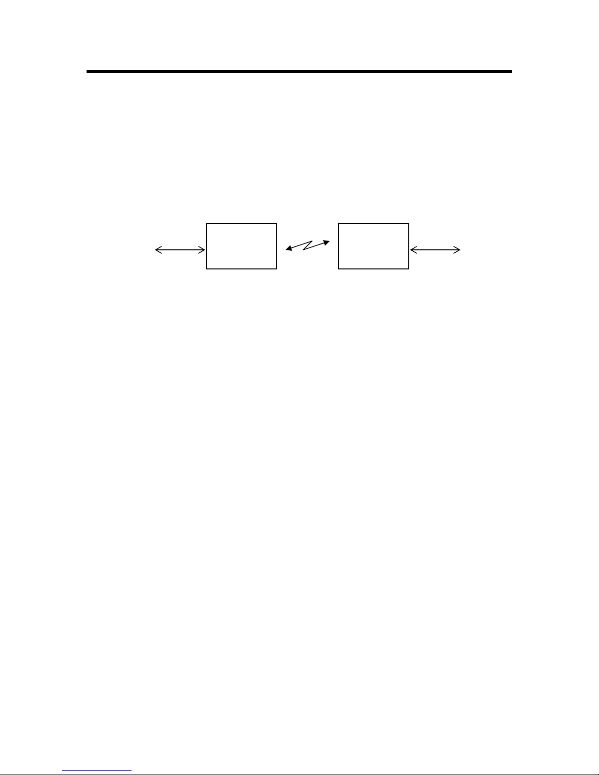
In order to conserve the available bandwidth, the FreeWave HT Ethernet Modems
have a MAC address filter. Each packet received by the Ethernet interface from the
LAN is checked for the destination MAC address against the filter table. If the address
is contained in the table, the packet is not forwarded across the radio link. If the
address is unknown, or known to be across the radio link, then the packet is
forwarded. An address is only added to the filter table after the Ethernet interface
positively determines that the MAC address in question is not across the radio link.
Each entry in the table has a lifetime of 4.5 minutes, to facilitate changing network
conditions, and roaming across networks.
The HT Ethernet High Throughput Modem has a Data Transmission RF Bit Rate of
867kbps in Point to Point mode, 614kbps in Point to Multipoint mode.
FreeWave
Ethernet
Modem
Radio Link
FreeWave
Ethernet
Modem
Ethernet,
LAN, PC
LAD0013AB Rev H 3 of 11
Page 4

FreeWave Technologies HT Ethernet Addendum
900MHz
V1.0h
Back Panel:
NORMAL/CROSSOVER:
Switches the RJ45 connector from normal wiring to
crossover wiring to avoid the need for a crossover cable.
LAN:
RJ45 connector, for
Ethernet 10Base-T
network.
DIAG: 3-pin connector for diagnostics
and programming of the radio. Diagnostic
cable, part number ASC0409DC, is
available from FreeWave.
POWER: 2.1 mm coaxial power connector.
6 – 30 V DC, center pin is positive.
RESET:
Push button to reset
the Ethernet interface,
ONLY. (It does
invoke the Set-up
mode)
not
ANTENNA: see Install Guide.
LAD0013AB Rev H 4 of 11
Page 5

FreeWave Technologies HT Ethernet Addendum
900MHz
V1.0h
Front Panel:
The modem has 2 rows of LED's. The bottom row of LED's is described in the Main
Manual. The top row has 7 LED’s that indicate the state of the Ethernet Interface.
The Ethernet Modem has 2 major components: the Ethernet interface port (the Data
Port) and the RF Modem (radio link). These devices must both be configured properly
for the network to function.
LAN
All other LED’s on the top row
show the activity of the
Ethernet port.
LINK: green = the modem is connected to its LAN.
TX: green = the modem is transmitting to another modem over the radio link.
Ethernet
Interface
The TX and RX LED’s in the
between the Ethernet Interface
RX: green = the modem is receiving from another modem over the radio link.
LTX: green = the modem is sending data to its LAN.
Modem
Radio
Modem
top row show the activity
and the Radio Modem.
The LED’s on the bottom row
show the status and activity of
Radio Link
the Radio Link.
LRX: green = the modem is receiving data from its LAN.
COL: red flash = the modem saw a collision on the LAN.
ERR: red flash = the modem saw an error on the LAN
See Main Manual
LAD0013AB Rev H 5 of 11
Page 6

FreeWave Technologies HT Ethernet Addendum
900MHz
V1.0h
Setup:
To program the modem, proceed as described in the Main Manual, with the following
exceptions:
• Capital U on the diagnostics port brings up the setup menu.
• You must use the diagnostic port (there's no RS232 Data Port in this modem)
• You must select the following settings.
Setup Menus
NOTE: The Baud Rate setting is neither the over the air data rate of the Radio Link, nor the data
rate of the Ethernet 10Base-T connection to the LAN. This Baud Rate strictly sets the protocol
internal to the Modem, between the Ethernet Interface and the RF modem.
Menu 1,
SET BAUD RATE
Modem Baud is 1382400 Must be “9” (1382.4Kbps)
(0) 230,400
(1) 115,200
…
(9) 1382.4KB
(A) Data, Parity 0 Must be "0" (Default)
(B) MODBus RTU 0 Must be "0" (Disabled)
(C) RS232/485 0 Must be "0" (TTL)
(D) Setup Port 2 Must be "2"* (Diagnostics port used for Set-up)
(E) TurnOffDelay 0 TurnOnDelay 0 No effect "0" (Default for both)
(F) FlowControl 1 Must be "1" (CTS flow control)
Menu 1, Submenu F
Ethernet/IP Radio Setup
(0) Ethernet Mode 1 Must be set to "1"*
(1) Half/Full Duplex 0 Select either, depending on your network
(2) Slave IP Stack 0 Must be set to “1”
(3) Slave UDP Mode 0
(4) IP Address 255.255.255.255 Used for diagnostics only
(5) Port Address 4131 Default Port Address
(6) IP Address 2 255.255.255.255
(7) Port Address 2 6535
(8) MAC Filter 0 0 disables internal MAC filter. 1 enables.
*NOTE: Once the "Ethernet Mode" setting is set to 1 (Menu 0, Submenu F, Option 0), the "Set-Up
Port" (Menu1, option D) can no longer be changed. Therefore, it is important to ensure the "SetUp Port" is set at "2", prior to enabling the "Ethernet Mode".
LAD0013AB Rev H 6 of 11
Page 7

FreeWave Technologies HT Ethernet Addendum
900MHz
V1.0h
Menu 2,
The Call Book is to be set as normal for Point to Point configurations. Network ID (Menu 5,
option 6) is recommended for Point to Multipoint networks.
Menu 3 (for Point to Point)
RADIO PARAMETERS
(0) FreqKey 5
(1) Max Packet Size 9 Recommended: "9" (for Asymmetric Data)
(2) Min Packet Size 1 Recommended: "1" (for Asymmetric Data)
(3) Xmit Rate 1
(4) RF Data Rate 2 Must be 2 if option B Delay (0-70) is invoked (set
to anything other than 0)
…
(A) High Noise 0
(B) Delay (0-70) 2 Used for range distance over 15 miles. All
Radios in network must have the same value.
(C) RemoteLED 0
(D) WideBand 0 Reserved for future use.
(E) Encryption 0 Enables 256 bit encryption, configurable in
EZConfig only.
Menu 3 (for Point to Multipoint)
RADIO PARAMETERS
(0) FreqKey 5
(1) Max Packet Size 9 Recommended: "9" (for Asymmetric Data)
(2) Min Packet Size 1 Recommended: "1" (for Asymmetric Data)
(3) Xmit Rate 1
(4) RF Data Rate 3 Must use: “3” for Multipoint networks
…
(B) Delay (0-70) 0 Option not available in Multipoint Mode.
(C) RemoteLED 0
(D) WideBand 0 Reserved for future use.
(E) Encryption 0 Enables 256 bit encryption, configurable in
EZConfig only.
Menu 5 (for Point to Multipoint)
MULTIPOINT PARAMETERS
(0) Number Repeaters 1 Set to "0" (if none) or "1" (if any)
…
(A) Slave/Repeater 0
should not be used with Ethernet radios.
This functio n is not supported and therefore
* The new Option (B) Delay (0-70) has been created for the purpose of adjusting the timing of the
radios when used at distances of over 15 miles. The value will increment by 1 for each 1.07 miles
over 15 miles the longest link in the network accommodates. Throughput is reduced slightly for
each increment of the Delay value. The Data Rate setting must be set to a value of 2.
NOTE: The Delay Setting MUST be the same in ALL Radios in the network.
LAD0013AB Rev H 7 of 11
Page 8

FreeWave Technologies HT Ethernet Addendum
900MHz
V1.0h
Errata for Firmware Versions
The Following are known issues with Firmware version 2.54F:
• Firmware version 2.54F is the first release of HT firmware that is field upgradeable. This
firmware also supports over the air firmware upgrades.
Point to Point Functionality
• Wideband mode is not operational.
• Slave/Repeater is not supported.
• Frequency Zones are not supported.
• Only 3 Frequency tables are available (0, 1 and 2).
• Serial Slave UDP mode is not Supported
Point to Multipoint Functionality
• Delay Option is not functional.
• Data Rate of 2 should not be used.
• Wideband mode is not operational.
• Slave/Repeater is not supported.
• Frequency Zones are not supported.
• Only 3 Frequency tables are available (0, 1 and 2).
• Serial Slave UDP mode is not Supported
The Following are known issues with Firmware version 2.55:
Overall (Point to Point and Point to Multipoint) Functionality
• Wideband mode is not operational.
• Slave/Repeater is not supported.
• Frequency Zones are not supported.
• Only 3 Frequency tables are available (0, 1 and 2). Note the full compliment of 7 (0-6) are
selectable however, the only 3 Frequency tables that are supported are Standard, Australian
and Standard 2.
• Serial Slave UDP mode is not Supported
Point to Point Functionality
Improvements:
• Bug fixed in Encryption. Encryption is Case Sensitive.
• Delay Distance feature functions but does not support Repeaters.
Point to Multipoint Functionality
• Delay Option is not functional.
• Data Rate of 2 is not supported.
Improvements:
• Bug fixed in Encryption. Encryption is Case Sensitive.
LAD0013AB Rev H 8 of 11
Page 9

FreeWave Technologies HT Ethernet Addendum
900MHz
V1.0h
The following are known issues with Firmware version 2.58:
Overall (Point to Point and Point to Multipoint) Functionality
• Wideband mode is not operational.
• Slave/Repeater is not supported.
• Frequency Zones are not supported.
• Only 3 Frequency tables are available (0, 1 and 2). Note the full compliment of 7 (0-6) are
selectable however, the only 3 Frequency tables that are supported are Standard, Australian
and Standard 2.
• Serial Slave UDP mode is not Supported
Point to Point Functionality:
• Delay Distance feature functions, but does not support Repeaters.
Point to Multipoint Functionality
• Delay Option is not functional.
• Data Rate of 2 is not supported.
Improvements:
• Radio lock-up issue in networks with repeaters was re solved.
The following are known issues with Firmware version 7.60:
Overall (Point to Point and Point to Multipoint) Functionality
• Wideband mode is not supported
• Slave/Repeater mode is not supported
Point to Point Functionality:
• Delay Distance option does not support repeaters
Point to Multipoint Functionality:
• Delay distance option is not supported
• RF Data Rate of 2 is not supported
Improvements:
• Firmware revision number has been changed to 7.xx, to differentiate HT firmware from FGR
firmware
•
Frequency zones are now supported
• All hop table versions are now supported
•
CTS lock-up issue has been resolved
LAD0013AB Rev H 9 of 11
Page 10

FreeWave Technologies HT Ethernet Addendum
900MHz
V1.0h
Installation:
To install the modem, proceed as described in the standard FGR user manual, with the following
exceptions:
• Connect the modem to the LAN with a CAT5 RJ45 Ethernet cable.
• Use the "Normal/Crossover" switch to select the polarity of the Ethernet connection. If
connecting to a switch, router or hub, select "Normal". If connecting to a NIC or a modem,
select "Crossover". However, if you are using a crossover cable, then use the opposite
settings of the switch.
• If required, use the top row of LED’s for troubleshooting the Ethernet Interface.
Troubleshooting:
To troubleshoot the modem, proceed as described in the Main Manual. Additionally, use the top
row of LED’s in this Ethernet modem as troubleshooting tools.
• No data is being passed between the LAN’s.
Upon power up, the Ethernet interface’s MAC filtering table can become corrupted, and must
be reset, or allowed to timeout. After power up, press the reset button on the back of the
FreeWave Ethernet, or allow 4.5 minutes to pass and the table to reset.
• The LINK LED is off:
The Modem has not successfully connected to the LAN.
Make sure that the Modem is powered On.
Make sure that the Ethernet device connected to the Modem is On.
Make sure the Modem and the Ethernet device are connected with a good Ethernet cable.
Try switching the "Normal/Crossover" switch to the opposite position.
Ensure the Ethernet device is set for auto-detect, or 10BaseT.
• The TX LED stays on:
Data is not successfully going from this modem's LAN to the other modem's LAN.
Make sure the radio link is working (see Main Manual).
Make sure both modems are linked to their respective LANs (modems' LINK LED’s a re on).
• The RX LED stays on:
Data isn't going between this modem and its LAN.
The Ethernet device to which this modem is connected isn't receiving data.
• The COL LED flashes:
There are collisions on this modem's LAN.
Collisions are normal when the modem is connected to the LAN is through a hub (it simply
means that two Ethernet devices tried to send data through the hub at the same time). The
Ethernet network is designed handle such collisions.
Collisions do not happen when the modem is connected directly through a switch, a NIC, or a
router.
• The ERR LED flashes:
A data buffer is getting full.
This typically occurs if the radio settings are incorrect. This also occurs when the radio link,
or the LAN link are not present. Check the radio settings, the Radio Link, and the LAN link.
Try pressing the Reset button on the back panel to reset the Ethernet Interface.
LAD0013AB Rev H 10 of 11
Page 11

FreeWave Technologies HT Ethernet Addendum
900MHz
V1.0h
Glossary of Terms:
Ethernet Modem: The entire FreeWave modem, which includes a Radio Modem
and an Ethernet Interface.
Ethernet Bridge: A bridge between two Ethernet LANs, using an Ethernet modem
at each end.
Radio Modem: The radio portion of the Ethernet Modem. It communicates with
other radio modems.
Ethernet Interface: The Ethernet portion of the Ethernet Modem. It translates and
filters data between the LAN and the Radio Modem.
Radio Link: The link between FreeWave radios.
LAN: (Local Area Network): A computer network, such as Ethernet.
Collision: The condition when one LAN device tries to transmit while
another device is already transmitting.
NIC: (Network Interface Card): A device that translates between a
LAN and a computer, typically found inside a personal computer.
Switch: A smart devic e for connecting many Ethernet devices together.
Router: A smart device for directing the Ethernet packets from one
network to another.
Hub: A dumb device for connecting many Ethernet devices together.
Ethernet Device: Any device that attaches to an Ethernet LAN, typically using an
RJ45 connector.
Asymmetric Data Data that flows primarily in one direction.
LAD0013AB Rev H 11 of 11
 Loading...