

Page 1
GX Serial Wireless Data Radios
GX-C
GX-CE
GX-T
Covering Firmware v9.7.9
User & Reference Manual
Part Number: LUM0034AA
Revision: May-2018
Page 2

GX-C, GX-CE, GX-T
User & Reference Manual
Warranty Information
FreeWave Technologies, Inc. warrants your FreeWave® Wireless Data Radio against defects in materials and
manufacturing for a period of three years from the date of shipment, depending on model number. In the event of
a Product failure due to materials or workmanship, FreeWave will, at its discretion, repair or replace the Product.
For evaluation of Warranty coverage, return the Product to FreeWave upon receiving a Return Material
Authorization(RMA).
IN NO EVENT WILL FREEWAVE TECHNOLOGIES, INC., ITS SUPPLIERS, OR ITS LICENSORS BE LIABLE FOR ANY DAMAGES ARISING
FROM THE USE OF OR INABILITY TO USE THIS PRODUCT. THIS INCLUDES BUSINESS INTERRUPTION, LOSS OF BUSINESS
INFORMATION, OR OTHER LOSS WHICH MAY ARISE FROM THE USE OF THIS PRODUCT. OEM CUSTOMER’S WARRANTY PERIODS
CAN VARY.
Warranty Policy will not apply in the following circumstances:
1. If Product repair, adjustments, or parts replacements are required due to accident, neglect, or undue
physical, electrical, or electromagnetic stress.
2. If Product is used outside of FreeWave specifications as stated in the Product's data sheet.
3. If Product has been modified, repaired, or altered by Customer unless FreeWave specifically authorized
such alterations in each instance in writing. This includes the addition of conformal coating.
Safety Information
The products described in this manual can fail in a variety of modes due to misuse, age, or malfunction. Systems
with these products must be designed to prevent personal injury and property damage during product operation
and in the event of product failure.
Warning! Do not remove or insert the Ethernet or diagnostics cable while circuit is live unless the
area is known to be free of ignition concentrations of flammable gasses or vapors.
Warning! Do not connect the GX-C, GX-CE, GX-T series radios to DC power without terminating the
antenna port to a suitable load, such as a 50 ohm antenna, or an attenuator with a power rating
greater than or equal to 2 W. Powering up without a load attached will damage the radio and void
the warranty.
FreeWave Technologies, Inc.
5395 Pearl Parkway, Suite 100
Boulder, CO 80301
Toll Free: 1.866.923.6168
Fax: 303.786.9948
Copyright © 2018 by FreeWave Technologies, Inc.
All rights reserved.
www.freewave.com
303.381.9200
LUM0034AA Rev May-2018 Page 2 of 126 Copyright © 2018FreeWave
This document is the property of FreeWave Technologies, Inc. and contains proprietary information owned by
FreeWave. This document cannot be reproduced in whole or in part by any means without written permission from
FreeWave Technologies, Inc.
Page 3

GX-C, GX-CE, GX-T
User & Reference Manual
Table Of Contents
Preface 8
1. Overview 11
1.1. Choose a Radio Location 11
1.2. Choosing Point-to-Point or Point-to-MultiPoint Operation 12
1.2.1. Point-to-Point (PTP) Network 12
1.2.2. Point-to-MultiPoint (PTMP) Network 12
Differences between PTP and PTMP 12
1.3. Data Communication Link Examples 13
1.3.1. Example 1 - Point-to-Point Gateway to Endpoint 13
1.3.2. Example 2 - Gateway Repeater Endpoint 14
1.3.3. Example 3 - Two Repeaters 14
1.3.4. Example 4 - Multiple Radios 15
1.3.5. Example 5 - Point-to-MultiPoint 16
1.3.6. Example 6 - Point-to-MultiPoint with a Repeater Site 17
1.4. Finding the Product Serial Number 18
1.5. Powering the Radio 19
1.6. Configuration Tool Options 19
1.6.1. Tool Suite and Terminal Emulators 20
1.7. Radio Setup Mode 21
1.7.1. Using Tool Suite to Connect to and Program Radios 21
1.7.2. Access the Setup Menu Using a Terminal Emulator 22
1.7.3. Connecting and Disconnecting from HyperTerminal 24
1.7.4. Troubleshooting HyperTerminal 24
Change the COM Port 24
Change the Baud Rate 26
Change the Flow Control 27
Change the Parity 28
1.8. Upgrade the Radios to the Latest Software Version 29
2. Basic Radio Programming and Setup 30
2.1. Setting the Radio's Role in the Network and the Network Type 31
2.2. Establishing Communication with Instrumentation and Computers 34
2.2.1. Baud Rate 34
2.2.2. Data Parity 35
2.2.3. Flow Control 35
2.2.4. Modbus RTU 36
2.2.5. Serial Interface 37
LUM0034AA Rev May-2018 Page 3 of 126 Copyright © 2018FreeWave
This document is the property of FreeWave Technologies, Inc. and contains proprietary information owned by
FreeWave. This document cannot be reproduced in whole or in part by any means without written permission from
FreeWave Technologies, Inc.
Page 4

GX-C, GX-CE, GX-T
User & Reference Manual
2.2.6. Setup Port 37
2.2.7. Turn Off Delay 38
2.2.8. Turn On Delay 38
2.2.9. Use Break to Access Setup 38
2.3. Establishing Communication with Other Radios in the Network 40
2.3.1. Golden Settings 41
2.4. Designate the RF Transmission Characteristics 41
2.4.1. 2.4GHz Frequency Key (Golden Setting) 42
2.4.2. 2.4GHz Frequency Zones 43
2.4GHz Frequency Zones Table 43
Enable Frequency Zones in Tool Suite 44
Enable Frequency Zones using the Terminal Interface 45
2.4.3. 2.4GHzGovernment Rules 45
2.4.4. High Noise 46
2.4.5. 2.4GHz Hop Frequency Offset 46
2.4.6. 2.4GHz Hop Table Size 46
2.4.7. 2.4GHz Hop Table Version 47
2.4.8. Max Packet Size and Min Packet Size (Golden Setting) 47
2.4.9. MCU Speed 48
2.4.10. Remote LED 49
2.4.11. Retry Time Out 50
2.4.12. RF Data Rate (Golden Setting) 51
2.4.13. Slave Security 51
2.4.14. Transmit Power 52
2.4.15. Transmit Rate 53
3. Configuring Point-to-MultiPoint Networks 54
3.1. Point to MultiPoint Network Characteristics 55
3.1.1. Golden Settings 55
3.1.2. Master to Slave Communications 55
3.1.3. Slave to Master Communications 55
3.2. Point-to-MultiPoint Network Quick Start 56
3.2.1. Point-to-MultiPoint Network Quick Start (Tool Suite) 56
3.2.2. Point-to-MultiPoint Network Quick Start (Terminal Interface) 57
3.3. Point-to-MultiPoint Operation LEDs 59
3.4. Overlapping MultiPoint Networks 60
3.5. Establishing Communication with Other Radios in a MultiPoint Network 60
3.5.1. Using the Network ID in MultiPoint Networks 60
3.5.2. Using the Call Book in MultiPoint Networks 61
LUM0034AA Rev May-2018 Page 4 of 126 Copyright © 2018FreeWave
This document is the property of FreeWave Technologies, Inc. and contains proprietary information owned by
FreeWave. This document cannot be reproduced in whole or in part by any means without written permission from
FreeWave Technologies, Inc.
Page 5

GX-C, GX-CE, GX-T
User & Reference Manual
3.5.3. Programming Point-to-MultiPoint Extended Call Book 62
3.6. Setting Other MultiPoint Parameters 63
3.6.1. 1 PPS Enable Delay 63
Setup 1PPS Enable/Delay 63
Calibrate a Slave Radio in 1PPS Enable/Delay Mode 64
3.6.2. Diagnostics 64
3.6.3. DTR Connect 64
3.6.4. Local Mode 65
3.6.5. Master Packet Repeat 66
3.6.6. Master Packet Repeat in MultiPoint Networks with Repeaters 67
3.6.7. Max Slave Retry 67
3.6.8. Radio ID 67
3.6.9. Radio Name 68
3.6.10. Repeater Frequency 68
3.6.11. Repeaters 68
3.6.12. Retry Odds 69
3.6.13. Slave / Repeater 70
3.7. Conserving Power 71
3.7.1. Low Power Mode 71
3.8. Reading Diagnostics in Tool Suite 73
4. Configuring Point-to-Point Networks 75
4.1. Point-to-Point Network Quick Start 75
4.1.1. Point-to-Point Network Quick Start (Tool Suite) 75
4.1.2. Point-to-Point Network Quick Start (Terminal Interface) 77
4.2. Point-to-Point Operation LEDs 79
4.3. Using the Call Book in Point-to-Point Networks 80
4.3.1. Setting the Call Book in Tool Suite 81
4.3.2. Setting the Call Book in the Terminal Interface 81
4.3.3. Programming Point-To-Point Extended Call Book to Use Three or Four Repeaters 83
5. Advanced Programming 84
5.1. Working with Parallel Repeaters 85
5.1.1. Repeaters Data Transmitted on the Same Frequency Key 85
5.1.2. Adding a Repeater to the Network 86
5.2. Setting and Changing Radio Passwords 87
5.2.1. Setting the Password 87
5.2.2. Changing a Password 87
5.2.3. Disable a Password 88
5.3. Enable and Set Up AES Encryption 88
LUM0034AA Rev May-2018 Page 5 of 126 Copyright © 2018FreeWave
This document is the property of FreeWave Technologies, Inc. and contains proprietary information owned by
FreeWave. This document cannot be reproduced in whole or in part by any means without written permission from
FreeWave Technologies, Inc.
Page 6

GX-C, GX-CE, GX-T
User & Reference Manual
5.3.1. Encryption (Strength) 89
5.3.2. Encryption Key 90
5.3.3. Encryption Channel Key 91
5.3.4. Troubleshooting AES Setup 92
5.4. Low Baud Rates 93
5.5. Multi-Master Sync 93
5.6. Time Divisible Multiple Access (TDMA) 93
6. Viewing Radio Statistics 94
6.1. Antenna Reflected Power 94
6.2. Master-Slave Distance 95
6.3. Noise Level 95
6.4. Number of Disconnects 95
6.5. Radio Temperature 96
6.6. Rate % (Receive Percentage Rate) 96
6.7. Signal Level 96
6.8. Transmit Current 97
7. Routing Communications through the Network 98
7.1. Assigning Subnet ID Values 98
7.1.1. Example 1: Subnet and Specific Path Communication 99
7.1.2. Example 2: Subnet and Communication Required through Repeaters 100
7.1.3. Example 3: Subnet and Optional Slave Communication 101
8. GX Serial Wireless Data Radios Pinouts 102
8.1. Operational RS422 and RS485 Information 102
8.2. Pinout Assignments and Descriptions 103
8.3. RF Board Level Pinout 104
8.4. RS-232 Pin Assignments (DB-9) 105
8.5. RS422 and RS485 Full Duplex Pinouts 106
8.6. RS485 Half Duplex Pinouts 106
9. Troubleshooting 107
9.1. Troubleshooting Flowchart 108
9.2. Unlicensed Serial Radio - Specific Troubleshooting 109
9.3. General Troubleshooting 109
10. GX-C, GX-CE, GX-T Release Notes 112
10.1. ETSI TDMA Compliance 112
10.1.1. TDMA Settings 113
RF Data Rate Setting of 3 - Normal 113
RF Data Rate Setting of 2 - High 113
10.1.2. Standard Mode Settings 114
LUM0034AA Rev May-2018 Page 6 of 126 Copyright © 2018FreeWave
This document is the property of FreeWave Technologies, Inc. and contains proprietary information owned by
FreeWave. This document cannot be reproduced in whole or in part by any means without written permission from
FreeWave Technologies, Inc.
Page 7

GX-C, GX-CE, GX-T
User & Reference Manual
Point-to-Point and MultiPoint Mode 114
10.1.3. Calculations 114
TDMA Mode 115
Point-to-Point and MultiPoint Mode 115
10.1.4. Standards and Editions 115
10.2. Version v9.7.9 115
Appendix A: GX-C, GX-CE, GX-T Technical Specifications 117
Appendix B: GX-C Mechanical Drawing 120
Appendix C: 2.4GHz Factory Default Settings 121
Appendix D: FreeWave Legal Information 123
LUM0034AA Rev May-2018 Page 7 of 126 Copyright © 2018FreeWave
This document is the property of FreeWave Technologies, Inc. and contains proprietary information owned by
FreeWave. This document cannot be reproduced in whole or in part by any means without written permission from
FreeWave Technologies, Inc.
Page 8

GX-C, GX-CE, GX-T
User & Reference Manual
Preface
Thank you for purchasing the FreeWave GX Serial Wireless Data Radios radio.
This document includes information about the FreeWave GX-C, GX-CE, GX-T serial radio:
l A basic introduction to the radio and how to determine the mode to run it in.
l Examples of how FreeWave radios can exist in a network with other radios.
l How to access the setup parameters available on the radio.
l Basic radio programming and setup information that applies to all network types.
l Considerations and quick starts for the network design, including charts of LED meanings.
l Details about defining a MultiPoint network including the use of Subnet IDs to route
information through the network.
l Steps to view statistics about a radio's performance.
l Pinouts and mechanical drawings.
Additional Information
This User Manual covers settings and configurations that apply to GX-C FreeWave radios.
Some radio models have specific settings and configurations that apply to only that model. For
information about a specific model or additional information about using the radios, see these
addendums and Application Notes:
l Cathodic Protection User Manual Addendum
l Application Note #5412: Synchronizing Collocated Masters (Multi-Master Sync Mode)
l Application Note #5476: Mode 6
l Mode 6 is designed to give control of which Slave a Master links to in a Point-to-Point
configuration.
LUM0034AA Rev May-2018 Page 8 of 126 Copyright © 2018FreeWave
This document is the property of FreeWave Technologies, Inc. and contains proprietary information owned by
FreeWave. This document cannot be reproduced in whole or in part by any means without written permission from
FreeWave Technologies, Inc.
Page 9
Preface
l Application Note : #5437: DTR to CTS Line Alarm Feature
l Application Note #5457: Local Mode
GX-C, GX-CE, GX-T
User & Reference Manual
For information about installing radios, see the 2.4 GHz Wireless Radios InstallationGuide.
Note: FreeWave documentation is available at www.freewave.com.
Contact FreeWave Technical Support
For up-to-date troubleshooting information, check the Support page at www.freewave.com.
FreeWave provides technical support Monday through Friday, 8:00 AM to 5:00 PM Mountain
Time (GMT -7).
l Call toll-free at 1.866.923.6168.
l In Colorado, call 303.381.9200.
l Contact us through e-mail at moreinfo@freewave.com.
Document Styles
This document uses these styles:
l FreeWave applications appear as: FreeWave.
l Parameter setting text appears as: [Page=radioSettings]
l File names appear as: configuration.cfg.
l File paths appear as: C:\Program Files (x86)\FreeWave Technologies.
l User-entered text appears as: xxxxxxxxx.
Caution: Indicates a situation that MAY cause damage to personnel, the radio, data, or
network.
Example: Provides example information of the related text.
FREEWAVE Recommends: Identifies FreeWave recommendation information.
Important!: Provides semi-cautionary information relevant to the text or procedure.
Note: Emphasis of specific information relevant to the text or procedure.
Provides time saving or informative suggestions about using the product.
LUM0034AA Rev May-2018 Page 9 of 126 Copyright © 2018FreeWave
This document is the property of FreeWave Technologies, Inc. and contains proprietary information owned by
FreeWave. This document cannot be reproduced in whole or in part by any means without written permission from
FreeWave Technologies, Inc.
Page 10
Preface
<Parameter Name>
Setting Description
Default Setting: The factory default setting for the parameter.
Options: The options the parameter can be set to.
Setup Terminal
Menu:
The menu path and field name to access the parameter using the terminal menus
available through the serial port.
Description: A description of what the parameter is and how it applies to the radio in the
network.
Warning! Indicates a situation that WILL cause damage to personnel, the radio, data, or
network.
Parameter Preference
The Parameter Preference table describes the available parameters.
GX-C, GX-CE, GX-T
User & Reference Manual
LUM0034AA Rev May-2018 Page 10 of 126 Copyright © 2018FreeWave
This document is the property of FreeWave Technologies, Inc. and contains proprietary information owned by
FreeWave. This document cannot be reproduced in whole or in part by any means without written permission from
FreeWave Technologies, Inc.
Page 11

GX-C, GX-CE, GX-T
User & Reference Manual
1. Overview
FreeWave radios operate in virtually any environment where data communications occur. The
radios act as data transmission devices, duplicating data in Point-to-Point, Point-to-MultiPoint, or
TDMA mode.
The GX includes:
l GX-C - Provides performance, reliability, and quality in a globally available spectrum and is
backward compatible with the I2 and IM radios.
l GX-CE - Provides the same performance and features as the GX-C, but in a ruggedized
enclosure.
l GX-CP - Cathodic Protection remote monitoring radio is a multipurpose, spread spectrum,
board-level product.
l The GX-CP has specific inputs and outputs for monitoring and reporting operational
values on pipelines, tanks, structures, and other facilities or structures and any other
metallic subject to environmental corrosion.
1.1. Choose a Radio Location
Placement of the FreeWave radio may have a significant impact on its performance. The key to
the overall robustness of the radio link is the height of the antenna.
When using an external antenna, placement of that antenna is critical to a solid data link. Other
antennas in close proximity are a potential source of interference.
Use the Radio Statistics to help identify potential problems. In general, FreeWave units with a
higher antenna placement will have a better communication link.
In practice, the radio should be placed away from computers, telephones, answering machines,
and other similar devices. The cable included with the radio provides ample distance for
placement away from other equipment.
LUM0034AA Rev May-2018 Page 11 of 126 Copyright © 2018FreeWave
This document is the property of FreeWave Technologies, Inc. and contains proprietary information owned by
FreeWave. This document cannot be reproduced in whole or in part by any means without written permission from
FreeWave Technologies, Inc.
Page 12
1. Overview
GX-C, GX-CE, GX-T
User & Reference Manual
Note: FreeWave offers directional and Omni-directional antennas with cable lengths ranging from 3
to 200 feet.
An adjustment as little as 2 feet in antenna placement may resolve noise issues.
In extreme cases, (e.g., Cellular Telephone tower interference) the band pass filters that
FreeWave offers may reduce out-of-bandnoise.
1.2. Choosing Point-to-Point or Point-to-MultiPoint Operation
Important!: For either a PTP or PTMP network, adding a Repeater cuts the network throughput by
50%.
1.2.1. Point-to-Point (PTP) Network
A PTP network work best when the network consists of one Master and one Slave radio.
Note: A maximum of four Repeaters can be added to extend the reach of the network.
1.2.2. Point-to-MultiPoint (PTMP) Network
In a PTMP network (also referred to as MultiPoint network) the Master radio is able to
simultaneously communicate with numerous Slave radios.
l A MultiPoint network functions with the Master broadcasting its messages to all Slave
radios.
l If requested by the Master, the Slave radios respond to the Master when given data by the
device connected to the data port. The response depends on the setup.
l The network reach can be extended with as many Repeaters as is required.
Differences between PTP and PTMP
l In a Point-to-Point network all packets are acknowledged, whether sent from the Master to
the Slave or from the Slave to the Master.
l In a MultiPoint network, the user determines the number of times outbound packets from
the Master or Repeater to the Slave or other Repeaters are sent.
l The receiving radio, Slave or Repeater, accepts the first packet received that passes the
32 bit CRC. However, the packet is NOT acknowledged.
l On the return trip to the Master, all packets sent are acknowledged or retransmitted until
they are acknowledged.
l Therefore, the return link in a MultiPoint network is generally very robust.
Traditionally, a MultiPoint network is used in applications where data is collected from many
instruments and reported back to one central site. The architecture of such a network is different
from Point-to-Point applications. These parameters influence the number of radios that can exist
in a MultiPoint network:
LUM0034AA Rev May-2018 Page 12 of 126 Copyright © 2018FreeWave
This document is the property of FreeWave Technologies, Inc. and contains proprietary information owned by
FreeWave. This document cannot be reproduced in whole or in part by any means without written permission from
FreeWave Technologies, Inc.
Page 13
1. Overview
l Data block size.
l The longer the data blocks, the fewer number of deployed Slave radios can exist in the
GX-C, GX-CE, GX-T
User & Reference Manual
network.
l Baud rate.
l The data rate between the radio and the device it is connected to could limit the amount
of data and the number of radios that can exist in a network
l The amount of contention between Slave radios.
l Polled Slave radios versus timed Slave radios.
l Repeater Use.
l Using the Repeater setting in a Point-to-Point or MultiPoint network decreases overall
network capacity by 50%.
Example: If the network polls once a day to retrieve sparse data, several hundred Slave radios could
be configured to a single Master.
However, if each Slave transmits larger amounts of data or data more frequently, fewer Slave radios
can link to the Master while receiving the same network performance.
When larger amounts of data are sent more frequently, the overall network bandwidth is closer to
capacity with fewerSlave radios.
1.3. Data Communication Link Examples
l Example 1 - Point-to-Point Gateway to Endpoint (on page 13)
l Example 2 - Gateway Repeater Endpoint (on page 14)
l Example 3 - Two Repeaters (on page 14)
l Example 4 - Multiple Radios (on page 15)
l Example 5 - Point-to-MultiPoint (on page 16)
l Example 6 - Point-to-MultiPoint with a Repeater Site (on page 17)
1.3.1. Example 1 - Point-to-Point Gateway to Endpoint
The versatility of FreeWave radios allows data links to be established using a variety of different
configurations.
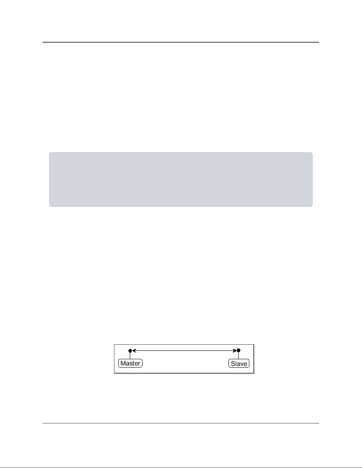
This example shows the most common and straight forward link; a Master communicating to a
Slave in a Point-to-Point link.
Figure 1: Master Communicating to a Slave in a Point-to-Point Link
LUM0034AA Rev May-2018 Page 13 of 126 Copyright © 2018FreeWave
This document is the property of FreeWave Technologies, Inc. and contains proprietary information owned by
FreeWave. This document cannot be reproduced in whole or in part by any means without written permission from
FreeWave Technologies, Inc.
Page 14
1. Overview
GX-C, GX-CE, GX-T
User & Reference Manual
1.3.2. Example 2 - Gateway Repeater Endpoint
This example shows a link using a Repeater.
l The Repeater may be located on a hilltop or other elevated structure enhancing the link
from the Master to the Slave.
l In this configuration, it may be desirable to use an external Omni directional antenna at the
Repeater.
l A Yagi antenna may be used at both the Master and Slave radios.
Note: Adding Repeaters to a network cuts the network throughput by 50%.
Figure 2: Master Communicating to a Slave in a Point-to-Point Link with a
Repeater
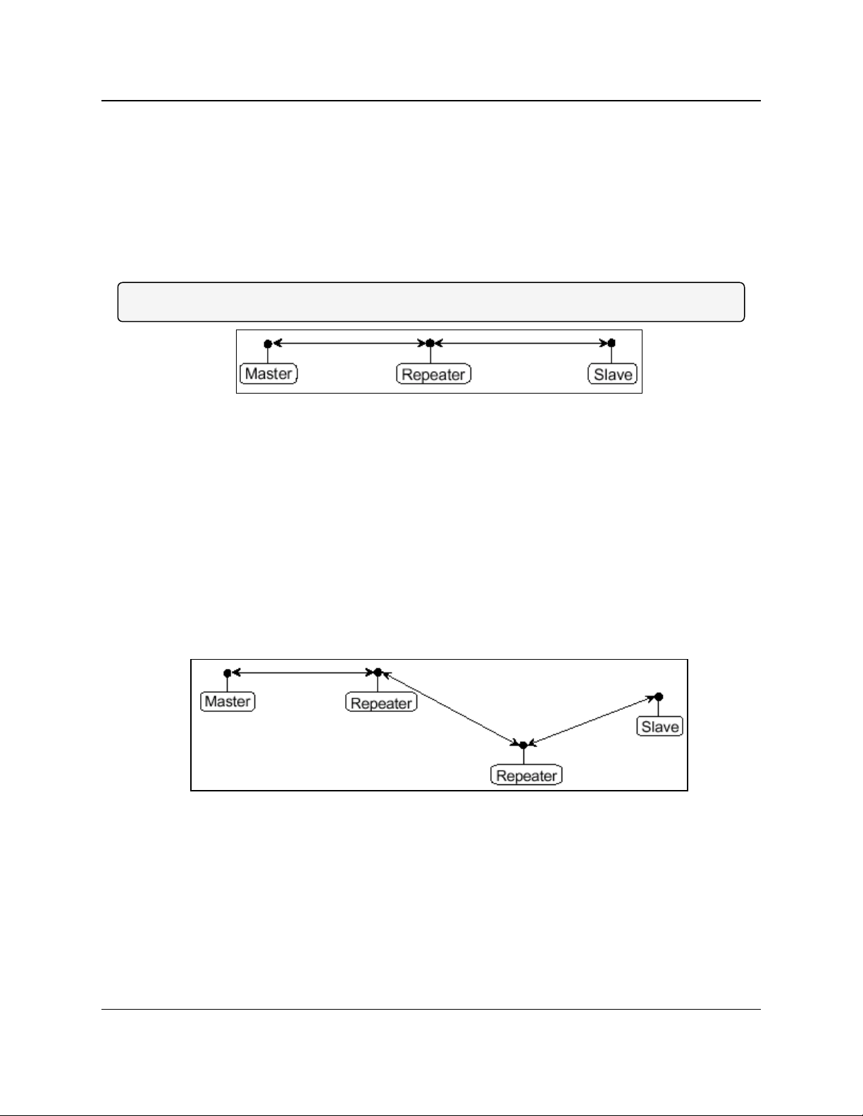
1.3.3. Example 3 - Two Repeaters
This example shows a link with two Repeaters between the Master and Slave.
l With two Repeaters there is more flexibility in getting around obstacles and greater total
range is possible.
l It may be desirable to use external Omni-directional antennas with the Repeaters, and
attaching a Yagi antenna to the Master and Slave radio to increase the range of the link.
l When two Repeaters are used no further degradation in the RF throughput of the link is
experienced.
Figure 3: Master Communicating to a Slave in a Point-to-Point Link with Two
Repeaters
LUM0034AA Rev May-2018 Page 14 of 126 Copyright © 2018FreeWave
This document is the property of FreeWave Technologies, Inc. and contains proprietary information owned by
FreeWave. This document cannot be reproduced in whole or in part by any means without written permission from
FreeWave Technologies, Inc.
Page 15
1. Overview
GX-C, GX-CE, GX-T
User & Reference Manual
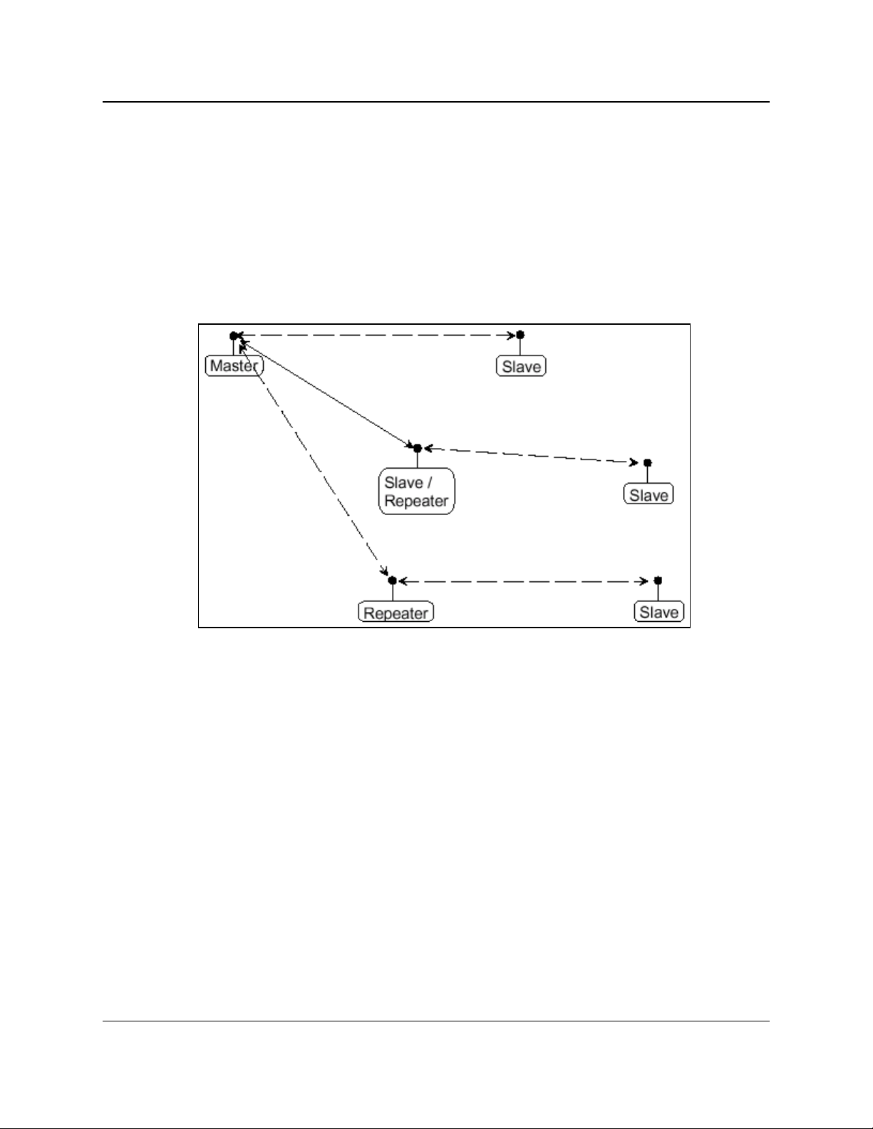
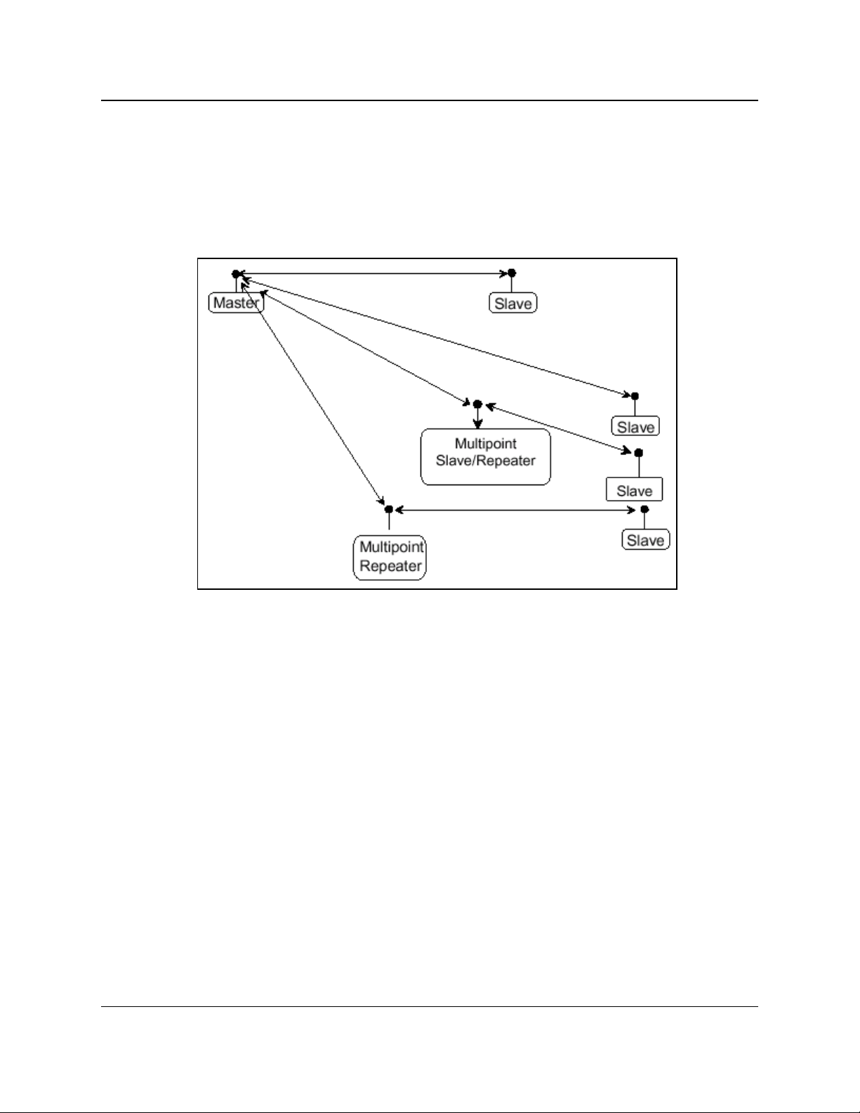
1.3.4. Example 4 - Multiple Radios
This example shows a configuration where a Master radio routinely calls a number of Slave radios
at different times.
l The Master radio is communicating with a radio designated as a Slave/Repeater that is
connected to a remote device.
l Since this device is placed in an elevated location, the radio may also be used as a
Repeater when it is not used as a Slave.
l At any time the Master may call any of the Slave radios, establish a connection, and send
and receive data.
Figure 4: Master Communicating to Multiple Slave Radios at Different Times
LUM0034AA Rev May-2018 Page 15 of 126 Copyright © 2018FreeWave
This document is the property of FreeWave Technologies, Inc. and contains proprietary information owned by
FreeWave. This document cannot be reproduced in whole or in part by any means without written permission from
FreeWave Technologies, Inc.
Page 16
1. Overview
GX-C, GX-CE, GX-T
User & Reference Manual
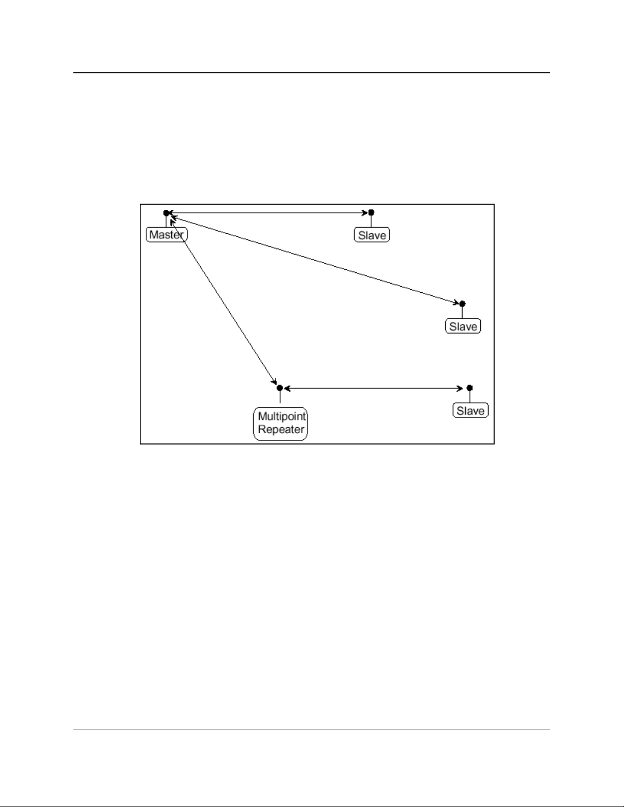
1.3.5. Example 5 - Point-to-MultiPoint
This example illustrates a standard Point-to-MultiPoint network.
l From the Master, any data is broadcast to all three Slave radios, one of which receives it
through a Multipoint Repeater.
l The data is sent out of the serial port of each of the three Slave radios.
l The end device should be configured to interpret the serial message and act on it if
necessary.
Figure 5: Master Communicating in a Point-to-MultiPoint Network
LUM0034AA Rev May-2018 Page 16 of 126 Copyright © 2018FreeWave
This document is the property of FreeWave Technologies, Inc. and contains proprietary information owned by
FreeWave. This document cannot be reproduced in whole or in part by any means without written permission from
FreeWave Technologies, Inc.
Page 17
1. Overview
GX-C, GX-CE, GX-T
User & Reference Manual
1.3.6. Example 6 - Point-to-MultiPoint with a Repeater Site
This example is a Point-to-MultiPoint network that uses one of the sites as a Slave/Repeater.
l This network functions in the same manner as a standard MultiPoint network with
Repeaters.
l However, the number of radios may be reduced with the use of the MultiPoint
Slave/Repeater feature.
Figure 6: Master Communicating in a Point-to-MultiPoint Network using a
Slave/Repeater
LUM0034AA Rev May-2018 Page 17 of 126 Copyright © 2018FreeWave
This document is the property of FreeWave Technologies, Inc. and contains proprietary information owned by
FreeWave. This document cannot be reproduced in whole or in part by any means without written permission from
FreeWave Technologies, Inc.
Page 18
1. Overview
GX-C, GX-CE, GX-T
User & Reference Manual
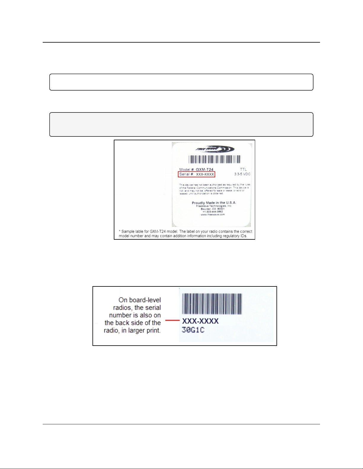
1.4. Finding the Product Serial Number
Each FreeWave radio is assigned a unique serial number.
Important!: This number is needed to contact FreeWave Technical Support.
The serial number is three digits, followed by a hyphen, then four digits (e.g., 111-1111), and is
printed on the FreeWave label on the radio.
Note: The example in this section is an image is of a GXM model.
The serial number information is in the same location on different models.
Figure 7: Example of the Serial Number for a GXM model
On radios that are not in an enclosure, the serial number is printed on a label on the back (the flat,
smooth side) of the radio.
This label is in larger print.
Figure 8: Example of the label and Serial Number of a non-enclosed radio
LUM0034AA Rev May-2018 Page 18 of 126 Copyright © 2018FreeWave
This document is the property of FreeWave Technologies, Inc. and contains proprietary information owned by
FreeWave. This document cannot be reproduced in whole or in part by any means without written permission from
FreeWave Technologies, Inc.
Page 19
1. Overview
GX-C, GX-CE, GX-T
User & Reference Manual
1.5. Powering the Radio
Connect the radio to a positive power supply with +6.0 to +27.0 VDC, typically +12.0 VDC.
Important!: GX-C, GX-CE, and GX-T radios are UL approved for voltage use between +6.0 to +27.0
VDC.
FREEWAVE Recommends: For guaranteed performance, FreeWave recommends using between
+7.5 to +30.0 VDC to power the radio.
Warning! If the power supply is above approximately +18.0 to +20.0 VDC, use a 1-ohm
resistor inline with B+ input to the radio.
Note: For more information about pinouts, see RF Board Level Pinout (on page 104).
If the power supply line runs outside the enclosure, use:
l electrostatic discharge (ESD) protectors to protect the radio from electric shock.
l transient voltage suppressors (TVS) to protect from an over-voltage situation.
Using both helps enhances reliable operation.
1.6. Configuration Tool Options
When the radio is in Setup mode, use these setup tools to configure the settings on the radio:
l Tool Suite- Tool Suite is the recommended method for programming the radios.
l It provides a group of tools for configuring the devices in the network and for monitoring
the network's performance.
l Use the Configuration application in Tool Suite to program changes to the radio's
settings.
l Tool Suite is available for download from www.freewave.com.
Note: For more information about using Tool Suite, see the Tool Suite User Manual in the
Tool Suite software.
l Terminal Emulator - A terminal emulator program (e.g., HyperTerminal or Tera Term)
offers many of the same configuration options available in the Configuration application in
Tool Suite.
l If running versions of the Windows® operating system prior to Windows® 7,
HyperTerminal is included in the operating system installation.
LUM0034AA Rev May-2018 Page 19 of 126 Copyright © 2018FreeWave
This document is the property of FreeWave Technologies, Inc. and contains proprietary information owned by
FreeWave. This document cannot be reproduced in whole or in part by any means without written permission from
FreeWave Technologies, Inc.
Page 20
1. Overview
Use the Setup Terminal application in Tool Suite to use and view the terminal menus.
It shows the same menus and provides the same programming settings as you see using a
terminal emulator.
FREEWAVE Recommends: Tool Suite is the recommended programming option. EZConfig can
still be used to program older radio models. However, newer radio models and newer firmware
versions are not available in EZConfig.
GX-C, GX-CE, GX-T
User & Reference Manual
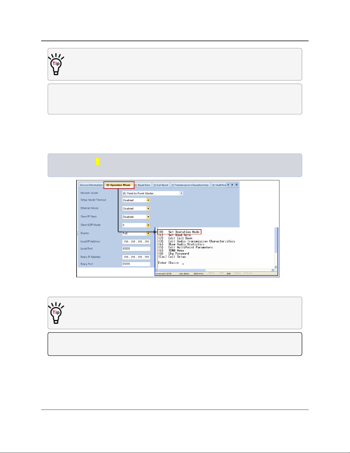
1.6.1. Tool Suite and Terminal Emulators
If using a terminal emulator, the tabs for a device in Tool Suite mirror the Setup main menu
selections.
Example: Option 0 on the Setup main menu in the terminal menu setup is Set Operation Mode.
The corresponding configuration tab for the device in Tool Suite is (0) Operation Mode.
Figure 9: Tool Suite menu Matched to Terminal menu
Use the Setup Terminal application in Tool Suite to use and view the terminal menus.
It shows the same menus and provides the same programming settings as you see using a
terminal emulator.
Note: In this document, if the setup procedure in the terminal emulator is different than the procedure
in Tool Suite, the terminal instructions are also included.
LUM0034AA Rev May-2018 Page 20 of 126 Copyright © 2018FreeWave
This document is the property of FreeWave Technologies, Inc. and contains proprietary information owned by
FreeWave. This document cannot be reproduced in whole or in part by any means without written permission from
FreeWave Technologies, Inc.
Page 21
1. Overview
GX-C, GX-CE, GX-T
User & Reference Manual
1.7. Radio Setup Mode
To read the current settings from or to program a radio, the radio must be in Setup mode. When a
radio is in Setup mode, all three LEDs appear solid green . These sections provide details
about how to access the radio's Setup mode using Tool Suite or the terminal interface.
Note: OEM boards may also enter Setup when Pin 2 on a 10- or 14-pin connector or Pin 8 on a 24-pin
connector is grounded, or using a break command.
For information about the break command, see Use Break to Access Setup (on page 38).
l The Setup Port parameter on the Baud Rate tab determines whether the main data port
or the diagnostics port is used to access the setup parameters for the radio. For more
information, see Setup Port (on page 37).
l Use the Setup Mode Timeout parameter on the Operation Mode tab to set the radio to
exit Setup Mode automatically. When the setting is enabled, if the radio has not received
any menu selections or programming information within 5 seconds, it exits Setup and
resumes its previous mode.
Note: For Setup mode troubleshooting information, see Troubleshooting (on page 107).
1.7.1. Using Tool Suite to Connect to and Program Radios
To read and program a radio using Tool Suite, connect the radio to a computer that runs the Tool
Suite software.
Use Tool Suite to set up a template version of a radio. Templates include settings that apply to
more than one radio in the network.
Note: For more information about using templates, see the Tool Suite User Manual in the Tool Suite
software.
Procedure
1. Connect a serial or diagnostic cable between the computer and the radio.
FREEWAVE Recommends: Using a diagnostic cable and the diagnostic port.
2. Connect the power supply to the radio and the power source and turn on the radio.
3. Open Tool Suite.
4. In the Applications window, click Configuration to open the Configuration application.
5. Verify the correct port is selected in the Com Port field on the Configuration ribbon.
6. Press the Setup button on the back of the FreeWave radio.
The radio is changed to Setup mode.
LUM0034AA Rev May-2018 Page 21 of 126 Copyright © 2018FreeWave
This document is the property of FreeWave Technologies, Inc. and contains proprietary information owned by
FreeWave. This document cannot be reproduced in whole or in part by any means without written permission from
FreeWave Technologies, Inc.
Page 22
1. Overview
Note: If connected to the diagnostics port, the radio changes to Setup mode automatically
when Read Radio is clicked in Tool Suite.
GX-C, GX-CE, GX-T
User & Reference Manual
7. Short Pins 2 and 4 (Brown to Black) on the 10-pin header next to the LEDs.
This places a board-level radio into Setup mode.
8. If using a data cable (FreeWave part number: ASC3610DB or ASC3610DJ), press the
Setup button on the data cable.
Note: If using the Setup Terminal application or a terminal emulator and using the gray
ribbon diagnostic cable (part number AC2009DC), or the black diagnostic cable (part number
ASC0409DC), the radio changes to Setup mode automatically when Read Radio is clicked
in Tool Suite.
All three LEDs on the radio are green and stay green as long as the radio is in Setup
mode.
9. On the Configuration ribbon, click Read Radio to read the radio's current settings.
10. Make the necessary parameter changes.
11. On the Network Title ribbon, use one of these options to send the changes to the radio:
l Click Quick to send only the changed parameters.
Note: This option is only available if Read Radio is clicked and parameter settings are
NOT sent from a template to the radio.
l Click All to send all the settings for all parameters.
l Click Default to set a device back to its factory default settings.
Note: For more information about using Tool Suite, see the Tool Suite User Manual in the Tool
Suite software.
1.7.2. Access the Setup Menu Using a Terminal Emulator
This procedure accesses the radio's Setup menu using the Setup Terminal application in Tool
Suite.
Note: For more information about using Tool Suite, see the Tool Suite User Manual in the Tool
Suite software.
Procedure
1. Plug a serial cable into the COM 1 port on the radio.
2. Connect the cable to a COM port on the computer running Tool Suite.
3. Connect the radio to a power source.
4. Open Tool Suite.
5. On the Applications window, click Setup Terminal.
LUM0034AA Rev May-2018 Page 22 of 126 Copyright © 2018FreeWave
This document is the property of FreeWave Technologies, Inc. and contains proprietary information owned by
FreeWave. This document cannot be reproduced in whole or in part by any means without written permission from
FreeWave Technologies, Inc.
Page 23
1. Overview
GX-C, GX-CE, GX-T
User & Reference Manual
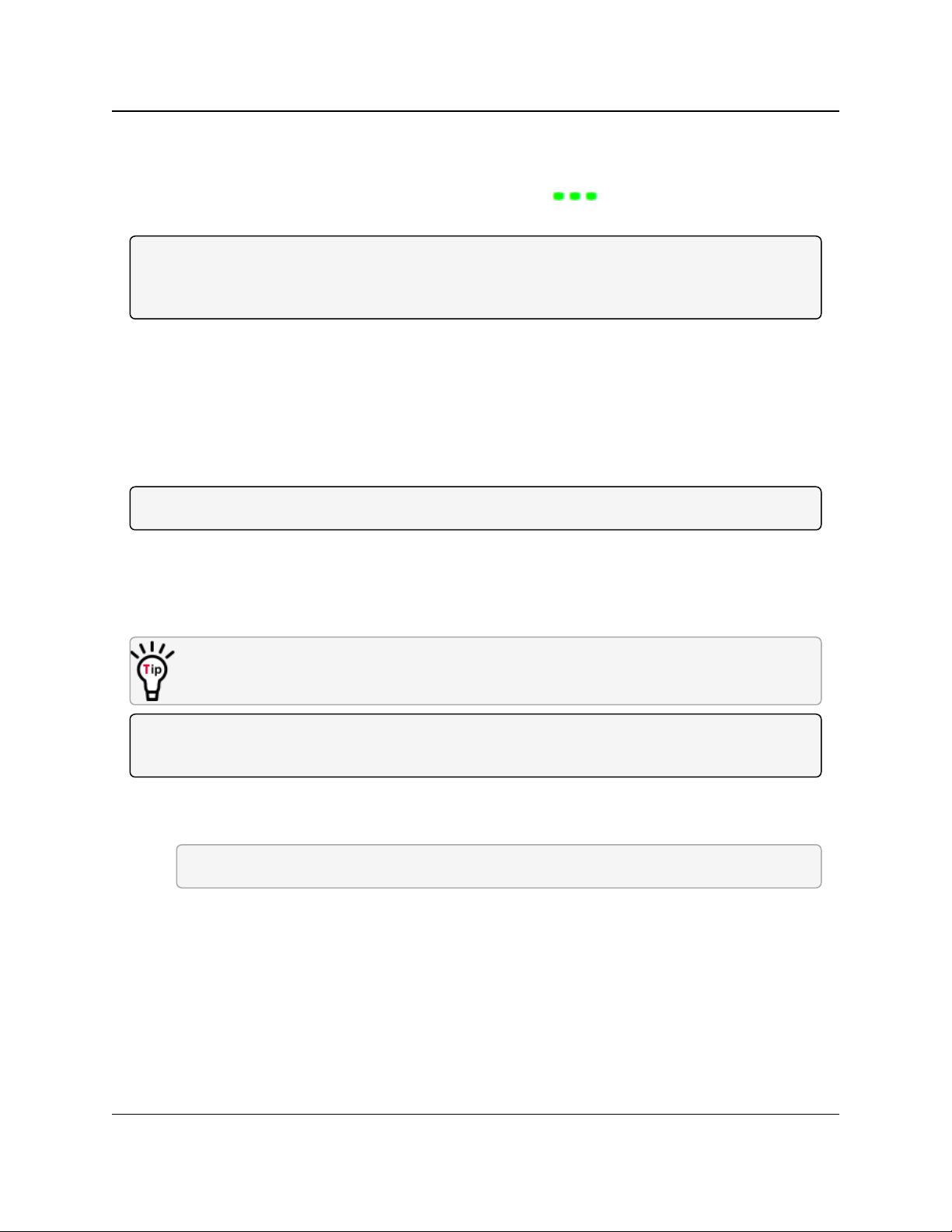
6. Click the Connection list box arrow in the top left of the window and select the COM port
on the computer the radio is connected to.
Figure 10: Connection list box
7. Click Connect.
8. To connect Setup Terminal to the radio, press the Setup button on the back of the
FreeWave radio.
If connected to the diagnostics port, press <Shift+U> to view the Setup menu.
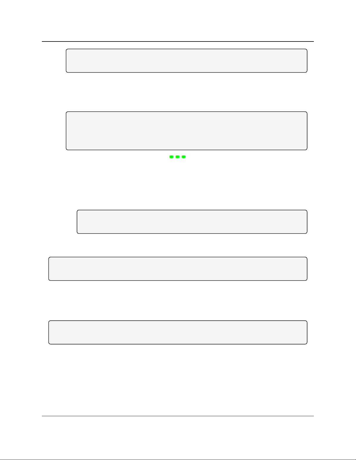
9. To view the Setup menu in board-level radios:
l Short pins 2 & 4 (Brown to Black) on the 10 pin header next to the LEDs.
Figure 11: GX-C Pin Layout
l If using a data cable (FreeWave part number: ASC3610DB or ASC3610DJ), press the
Setup button on the data cable.
l If using the gray ribbon diagnostic cable (P/N AC2009DC), or the black diagnostic
cable (P/N ASC0409DC), press <Shift+U> to view the Setup menu.
LUM0034AA Rev May-2018 Page 23 of 126 Copyright © 2018FreeWave
This document is the property of FreeWave Technologies, Inc. and contains proprietary information owned by
FreeWave. This document cannot be reproduced in whole or in part by any means without written permission from
FreeWave Technologies, Inc.
Page 24
1. Overview
GX-C, GX-CE, GX-T
User & Reference Manual
When Setup is activated, the FreeWave Setup Main Menu appears in the HyperTerminal
dialog box.
All three LEDs on the radio are green and stay green as long as the radio is in Setup
mode.
Important!: When navigating through the Setup menu and making changes to the parameters, the
parameters are sent immediately to the radio.
1.7.3. Connecting and Disconnecting from HyperTerminal
The HyperTerminal dialog box has several toolbar buttons.
To reconnect to HyperTerminal, disconnect from the current session.
1.
Click the Disconnect .
2.
Click the Call to reconnect.
Note: If the settings have not been saved they must be re-selected when HyperTerminal reconnects
to the radio.
1.7.4. Troubleshooting HyperTerminal
These are some common issues encountered while using HyperTerminal as the terminal
emulator.
l The steps to resolve the issue are specific to the HyperTerminal interface.
l Similar steps can be used when troubleshooting other terminal emulators.
Important!: When a change is made to the HyperTerminal settings in an open terminal session, the
connection must be disconnected then reconnected before the settings take effect.
l Change the COM Port (on page 24).
l Change the Baud Rate (on page 26).
l Change the Flow Control (on page 27).
l Change the Parity (on page 28).
Change the COM Port
Important!: Nothing appears on the screen after placing the radio into Setup mode.
This error usually indicates one of two things:
l The wrong COM port is selected.
l A null modem cable is being used.
LUM0034AA Rev May-2018 Page 24 of 126 Copyright © 2018FreeWave
This document is the property of FreeWave Technologies, Inc. and contains proprietary information owned by
FreeWave. This document cannot be reproduced in whole or in part by any means without written permission from
FreeWave Technologies, Inc.
Page 25
1. Overview
1.
Click .
GX-C, GX-CE, GX-T
User & Reference Manual
2. On the File menu, click Properties.
3. Click the Connect To tab.
4. Verify the correct COM port is selected.
5. Click OK to close the Properties dialog box.
6.
Click .
7. Return the radio to Setup mode.
The Setup menu screen appears.
If the radio has been previously configured, the wrong port could be used to access the Setup
menu.
Note: For more information, see Setup Port (on page 37). Try connecting to the other port.
LUM0034AA Rev May-2018 Page 25 of 126 Copyright © 2018FreeWave
This document is the property of FreeWave Technologies, Inc. and contains proprietary information owned by
FreeWave. This document cannot be reproduced in whole or in part by any means without written permission from
FreeWave Technologies, Inc.
Page 26

1. Overview
GX-C, GX-CE, GX-T
User & Reference Manual
Change the Baud Rate
Important!: Unrecognizable characters appear on the screen after placing the radio into Setup mode.
l Unrecognizable characters usually indicate a Baud Rate problem.
l The problem may also be that the radio under test is a TTL version or has been set to
RS485 and not RS232. If the radio is TTL or in RS485 mode, verify connection through the
Diagnostic port. Gibberish before the Setup button is pressed indicates Diagnostics is
enabled in a Master.
1.
Click .
2. On the File menu, click Properties.
3. Click Configure.
4. Change these settings and click OK:
l Baud Rate to 19200
l Data Bits to 8
l Parity to None
l Stop Bits to 1
l Flow Control to 1
5. Click OK to close the Properties dialog box.
6.
Click .
7. Return the radio to Setup mode.
The Setup menu screen appears.
LUM0034AA Rev May-2018 Page 26 of 126 Copyright © 2018FreeWave
This document is the property of FreeWave Technologies, Inc. and contains proprietary information owned by
FreeWave. This document cannot be reproduced in whole or in part by any means without written permission from
FreeWave Technologies, Inc.
Page 27

1. Overview
GX-C, GX-CE, GX-T
User & Reference Manual
Change the Flow Control
Important!: The Setup menu appears on the screen, but nothing happens when keys on the
keyboard are pressed.
l This error usually indicates flow control is turned on in a three-wire connection (Rx, Tx, and
Gnd).
Follow these steps if the connection uses a three-wire connection.
1.
Click .
2. On the File menu, click Properties.
3. Click Configure.
4. Change the Flow Control to None, and click OK.
5. Click OK to close the Properties dialog box.
6.
Click .
7. Return the radio to Setup mode.
The Setup menu screen appears.
LUM0034AA Rev May-2018 Page 27 of 126 Copyright © 2018FreeWave
This document is the property of FreeWave Technologies, Inc. and contains proprietary information owned by
FreeWave. This document cannot be reproduced in whole or in part by any means without written permission from
FreeWave Technologies, Inc.
Page 28
1. Overview
GX-C, GX-CE, GX-T
User & Reference Manual
Change the Parity
Important!: A connection exists, the terminal emulator is receiving data, and some data is correct,
but the remaining data is in unrecognizable characters.
l This error usually indicates a parity mismatch.
l To resolve this issue, verify the parity of the radio and the parity of HyperTerminal are set
the same.
l HyperTerminal’s parity settings are under the Properties menu.
l The FreeWave radio parity is found under the Baud Rate menu in the Setup menu.
1.
In HyperTerminal, click .
2. On the File menu, click Properties.
3. Click Configure.
4. Change the Parity to None, and click OK.
5. Click OK button to close the Properties dialog box.
6.
Click .
7. Return the radio to Setup mode.
The Setup menu screen appears.
LUM0034AA Rev May-2018 Page 28 of 126 Copyright © 2018FreeWave
This document is the property of FreeWave Technologies, Inc. and contains proprietary information owned by
FreeWave. This document cannot be reproduced in whole or in part by any means without written permission from
FreeWave Technologies, Inc.
Page 29
1. Overview
GX-C, GX-CE, GX-T
User & Reference Manual
1.8. Upgrade the Radios to the Latest Software Version
If Tool Suite is connected to a radio, and a new version of the software is available for that radio
model, an indication appears in the Configuration application's Device Information tab.
Use Tool Suite to upgrade the software on a serial radio connected directly to the computer using
the diagnostic cable.
Important!: An over-the-air upgrade using Tool Suite is not allowed.
FREEWAVE Recommends: If using a USB-to-serial converter cable, a software upgrade can take
a long time to complete.
Use USB-to-serial cables that include the FTDI Chip Set to shorten the upgrade time.
This inclusion is listed on the cable's packaging.
See the Application Note #5471 Optimizing Firmware Upgrade Speed While Using a USB-
Serial Adaptor for additional information (available at www.freewave.com).
Note: For more information about using Tool Suite, see the Tool Suite User Manual in the Tool
Suite software.
Procedure
1. With the radio connected to the computer through the COM port, open Tool Suite.
2. In the Applications window, click Configuration to open the Configuration application.
3. In the Firmware area of the Configuration application, click Upgrade Radio.
4. Click Yes at the prompt to proceed.
Tool Suite identifies the software version loaded on the connected device and shows the
latest version of software available for that model.
5. Click Yes to continue with the upgrade.
The system shows the progress of the software upgrade.
After the firmware upgrade is complete, a message appears confirming that the software
upgrade was successful.
LUM0034AA Rev May-2018 Page 29 of 126 Copyright © 2018FreeWave
This document is the property of FreeWave Technologies, Inc. and contains proprietary information owned by
FreeWave. This document cannot be reproduced in whole or in part by any means without written permission from
FreeWave Technologies, Inc.
Page 30

GX-C, GX-CE, GX-T
User & Reference Manual
2. Basic Radio
Programming and Setup
When setting up either a Point-to-MultiPoint network or a Point-to-Point network, the process for
setting up and programming a radio is the same.
This section describes these aspects of programming and setting up a radio:
l Setting the Radio's Role in the Network and the Network Type (on page 31).
l Establishing Communication with Instrumentation and Computers (on page 34).
l Establishing Communication with Other Radios in the Network (on page 40).
l Designate the RF Transmission Characteristics (on page 41).
LUM0034AA Rev May-2018 Page 30 of 126 Copyright © 2018FreeWave
This document is the property of FreeWave Technologies, Inc. and contains proprietary information owned by
FreeWave. This document cannot be reproduced in whole or in part by any means without written permission from
FreeWave Technologies, Inc.
Page 31

2. Basic Radio Programming and Setup
Operation Mode Description
Point-to-Point
Master (0)
This mode designates the radio as the Master in Point-to-Point mode.
The Master may call any or all Slaves designated in its Call Book.
In Point-to-Point mode the Master determines the setting used for most
of the transmission characteristics, regardless of the settings in the
Slave and/or Repeaters.
The settings NOT determined by the Master are:
l Hop Table settings
l Retry Time Out
l Slave Security
l Transmit Power
A quick method of identifying a Master is to power the radio.
Prior to establishing a link with a Slave, all three of the LEDs on the
Master are solid red .
GX-C, GX-CE, GX-T
User & Reference Manual
2.1. Setting the Radio's Role in the Network and the Network Type
Networks consist of a Master radio and any number of other components including Repeaters,
Slave radios, and radios that act as both a Slave and a Repeater. The first parameter to set in a
radio is its Operation or Modem mode.
The mode tells the radio what network type it is in (Point-to-Point or Point-to-MultiPoint) and what
role it plays (Master, Slave, or Repeater) in that network.
Note: The network type must match for all radios in a network.
If configuring a Point-to-MultiPoint network, verify the Modem Mode selection for radios in the
network starts with Point-to-MultiPoint.
When setting up the radio, remember that the settings on the Master control a number of
parameters.
Therefore, deploying the Master on the communications end where it is easier to access is
advised, but not necessary.
Set the Modem mode on the Operation Mode tab, using the Modem Mode field. These settings
are available in the Operation Mode menu in the terminal interface.
LUM0034AA Rev May-2018 Page 31 of 126 Copyright © 2018FreeWave
This document is the property of FreeWave Technologies, Inc. and contains proprietary information owned by
FreeWave. This document cannot be reproduced in whole or in part by any means without written permission from
FreeWave Technologies, Inc.
Page 32

2. Basic Radio Programming and Setup
Operation Mode Description
Point-to-Point
Slave (1)
This mode designates the radio as a Slave in Point-to-Point mode.
l The Slave communicates with any Master in its Call Book - either
directly or through a maximum of four Repeaters.
l When functioning as a Slave, the Entry to Call feature in the radio’s
Call Book is NOT operational.
l Set the Slave Security parameter to 1 to bypass the Call Book in the
Slave.
Note: For more information, see Slave Security on page 51.
Point–to-MultiPoint
Master (2)
This mode designates the radio as a Master in MultiPoint mode.
l This mode allows one Master radio to communicate simultaneously
with numerous Slaves and Repeaters.
l A Point-to-MultiPoint Master communicates only with other radios
designated as Point-to-MultiPoint Slaves or Point-to-MultiPoint
Repeaters.
Point-to-MultiPoint
Slave (3)
This mode designates the radio as a Slave in MultiPoint mode.
l This mode allows the Slave to communicate with a MultiPoint
Master.
l The Slave may communicate with its Master through one or more
Repeaters.
Point-to-Point Slave /
Repeater (4)
This mode designates the radio to act as either a Slave or Repeater,
depending on the instructions from the Master.
l The radio cannot act as both a Slave and a Repeater at the same
time.
l True Slave/Repeater functionality is only available in a MultiPoint
mode.
l Point-to-Point Slave/Repeaters have no security features.
l When a radio is designated a Point-to-Point Slave/Repeater, it
allows any Master to use it as a Repeater.
Note: Adding Repeaters to a network cuts the network
throughput by 50%.
GX-C, GX-CE, GX-T
User & Reference Manual
LUM0034AA Rev May-2018 Page 32 of 126 Copyright © 2018FreeWave
This document is the property of FreeWave Technologies, Inc. and contains proprietary information owned by
FreeWave. This document cannot be reproduced in whole or in part by any means without written permission from
FreeWave Technologies, Inc.
Page 33

2. Basic Radio Programming and Setup
Operation Mode Description
Point-to-Point
Repeater (5)
FreeWave allows the use of a maximum of four Repeaters in a Point-toPoint communications link, significantly extending the operating range.
l When designated as a Repeater, a radio behaves as a pass-through
link.
l All settings for the Call Book, baud rates, and transmission
characteristics are disabled.
l A Repeater connects with any Master that calls it.
l The Repeater must be set up properly in the Master's Call Book.
Note: Adding Repeaters to a network cuts the network
throughput by 50%.
Point-to-Point Slave /
Master Switchable (6)
Mode 6 allows the radio to be controlled entirely through software
commands.
l A number of key parameters in the FreeWave user interface may be
changed either directly using a terminal emulator or using script files.
l When the Point-to-Point Slave/Master Switchable option is
selected and the radio is not calling a Slave, it functions as a Slave
and accepts any appropriate calls from other radios.
Note: For more information, see Application Note #5476, Mode
6.
Point-to-MultiPoint
Repeater (7)
This option allows the radio to operate as a Repeater in a MultiPoint
network.
l A MultiPoint network can have as many Repeaters as necessary.
l If the Repeater is to act as a Slave/Repeater, set the Slave
Repeater parameter in the MultiPoint Parameters tab to Enabled.
Note: Adding Repeaters to a network cuts the network
throughput by 50%.
Mirrorbit Master (A)
Mirrorbit Slave (B)
As of May-2018, Mirrorbit Master and Mirrorbit Slave mode are not
supported.
Ethernet Options (F) This menu is used for Ethernet radios only.
GX-C, GX-CE, GX-T
User & Reference Manual
FreeWave Technologies, Inc.
FreeWave. This document cannot be reproduced in whole or in part by any means without written permission from
LUM0034AA Rev May-2018 Page 33 of 126 Copyright © 2018FreeWave
This document is the property of FreeWave Technologies, Inc. and contains proprietary information owned by
Page 34

2. Basic Radio Programming and Setup
Baud Rate
Setting Description
Default Setting 115200
Options 600, 1200, 2400, 4800, 9600, 19200, 38400, 57600, 76800, 115200, 230400
Terminal Menu (1) Set Baud Rate
Description: l This is the communication rate between the radio's data port and the
instrument it is connected to.
l This setting is independent from the baud rate for the other radios in the
network.
Note: With a poor RF link, this may actually result in slower data
communications.
l The Setup Port Baud Rate always defaults to 19,200 no matter how the Data
Port Baud Rate is set.
l The only exception is Mode 6.
l For more information, see Application Note #5476, Mode 6.
FREEWAVE Recommends: With a Baud Rate setting of 38,400 or
higher, FreeWave recommends using the lines of the Flow Control (on
page 35).
GX-C, GX-CE, GX-T
User & Reference Manual
2.2. Establishing Communication with Instrumentation and Computers
The settings on the Baud Rate tab are the communications settings between the radio and the
instrument or computer it is connected to (radio serial port to the device).
Important!: These settings are unique to each radio, and do not need to match across the network.
Example: A pair of radios may be used in an application to send data from remote process
instrumentation to an engineer's computer.
In this application, the Baud Rate for the radio on the instrumentation might be set to 9600 and the
radio on the polling host might be set to 57,600.
These settings are available in the Baud Rate menu in the terminal interface, and apply to both
Point-to-Point and Point-to-MultiPoint networks.
Note: See the Parameter Preference (on page 10) for a description of the parameter table's content.
2.2.1. Baud Rate
LUM0034AA Rev May-2018 Page 34 of 126 Copyright © 2018FreeWave
This document is the property of FreeWave Technologies, Inc. and contains proprietary information owned by
FreeWave. This document cannot be reproduced in whole or in part by any means without written permission from
FreeWave Technologies, Inc.
Page 35

2. Basic Radio Programming and Setup
Data Parity
Setting Description
Default Setting 0 (8, N, 1)
Options See Description.
Terminal Menu (1) Set Baud Rate > (A) Data Parity
Description: l Six data word length and parity configurations are available for use with
FreeWave radios.
l The default setting is 8-None-1 and is the most commonly used serial
communications protocol.
This table describes each option:
Option Data Bits Parity Stop Bits
0 8 None 1
1 7 Even 1
2 7 Odd 1
3 8 None 2
4 8 Even 1
5 8 Odd 1
Flow Control
Setting Description
Default Setting (0) None
Options l (0) None - No flow control CTS is active and de-asserts when buffering is 98%
full. Can pass XON/XOFF data but does not use it in any way.
l (1) RTS - Uses RTS/CTS (Request to Send/Clear to Send) for flow control.
l CTS performs the same way as in option (0) None.
l RTS must be activated for the radio to output data over the serial port.
l (2) DTR - Uses DTR/DSR (Data Terminal Ready/Data Set Ready) for flow
control.
l (3) DOT - Half Duplex.
Terminal Menu (1) Set Baud Rate > (F) FlowControl
2.2.2. Data Parity
GX-C, GX-CE, GX-T
User & Reference Manual
2.2.3. Flow Control
LUM0034AA Rev May-2018 Page 35 of 126 Copyright © 2018FreeWave
This document is the property of FreeWave Technologies, Inc. and contains proprietary information owned by
FreeWave. This document cannot be reproduced in whole or in part by any means without written permission from
FreeWave Technologies, Inc.
Page 36

2. Basic Radio Programming and Setup
Flow Control
Setting Description
Description: Specifies the hardware flow control for the data port on the radio.
Flow control is the process of managing the speed data is transmitted to not
overwhelm the device receiving the transmission.
FREEWAVE Recommends: Use Flow Control if the Baud Rate is
higher than 38,400.
Modbus RTU
Setting Description
Default Setting 0 (Disabled)
Options 0 to 9
Terminal Menu (1) Set Baud Rate > (B) ModbusRTU
Description: A setting other than 0 in this parameter causes the radio to wait for an amount of
time gathering data before sending out the RF link.
l 0 (Disabled) - The radio sends data out through its RF link as soon as the data
is received into the serial port. This is the default setting.
l 1 - The radio waits for a number of slots equal to two times the Master Packet
Repeat setting before sending the received data out the RF link.
Example: If the Master Packet Repeat parameter is set to 3, the radio
waits for 6 slots, gathering data up the whole time.
At the end of the 6 slots, the radio sends all received data in one “burst.”
This is the appropriate setting for most Modbus RTU devices.
l 2 or higher - The radio waits for a number of slots calculated using this
formula:
(Modbus RTU setting + Master Packet Repeat setting + 1) x 2
Example: In a radio where the Modbus RTU setting is 2 and the Master
Packet Repeat setting is 3, the radio waits for(2+3+1)x2, or 12 slots.
GX-C, GX-CE, GX-T
User & Reference Manual
2.2.4. Modbus RTU
Note: When using the radio in Modbus RTU mode, the Master Packet Repeat parameter setting on
the MultiPoint Parameters tab MUST match in every radio.
The Modbus RTU mode must be set to 1 when radios are configured in RS485 or RS422 mode.
LUM0034AA Rev May-2018 Page 36 of 126 Copyright © 2018FreeWave
This document is the property of FreeWave Technologies, Inc. and contains proprietary information owned by
FreeWave. This document cannot be reproduced in whole or in part by any means without written permission from
FreeWave Technologies, Inc.
Page 37

2. Basic Radio Programming and Setup
Serial Interface
Setting Description
Default Setting (0) RS232
Options l (0) RS232 - Also used for TTL.
l (1) RS422/Full Duplex RS485 - Modbus RTU mode must be enabled and
Turn Off Delay set to at least 4.
l (2) Half Duplex RS485 - Modbus RTU mode must be enabled and Turn Off
Delay set to at least 4.
l (3) DOT - DOT causes the CD line to indicate when data is transmitted on the
serial port from the radio.
l When the radio is not sending data to the serial port, CD is de-asserted.
l When the radio is sending data to the serial port, CD is asserted.
l The CD line no longer has any link state functionality.
l Turn Off Delay works as described in all radios.
l Turn On Delay works as described on any Slave or Slave/Repeater - it has
no functionality on the Master.
If set to anything other than 0, the Setup Port parameter in the Baud Rate tab
must be set to Diagnostics Only.
Terminal Menu (1) Set Baud Rate > (C) RS232/485
Description: Use this option to set the protocol of the data port for connection to an external
device.
Note: This setting must be 0 in TTL RF board products.
Setup Port
Setting Description
Default Setting (3) Both
2.2.5. Serial Interface
GX-C, GX-CE, GX-T
User & Reference Manual
2.2.6. Setup Port
Important!: Do NOT change this setting unless the correct programming cable is available for the
new setting.
LUM0034AA Rev May-2018 Page 37 of 126 Copyright © 2018FreeWave
This document is the property of FreeWave Technologies, Inc. and contains proprietary information owned by
FreeWave. This document cannot be reproduced in whole or in part by any means without written permission from
FreeWave Technologies, Inc.
Page 38

2. Basic Radio Programming and Setup
Setup Port
Setting Description
Options l (1) Main Only - Programming and reading a radio's setup information is done
through the data port.
l (2) Diagnostics Only - Programming and reading a radio's setup information
is done through the diagnostic port.
l If the Serial interface is set to anything other than RS232, then the Setup
Port must be set to Diagnostics Only.
l (3) Both - Programming and reading a radio's setup information is done
through either the data port or the diagnostic port .
Terminal Menu (1) Set Baud Rate > (D) Setup Port
Description: Determines which port on the radio, Main or Diagnostics, is used to access the
parameter settings in Tool Suite or enter the Setup main menu in the terminal
interface.
l The main data port is the RS232 port.
l The diagnostics port is a 3-pin connector on the rear panel of the OEM Mini
series radios.
l The diagnostic cable for this port (ASC0409DC) is available from
FreeWave.
l The OEM modules use a 2-row, 2 mm female connector.
l The diagnostic cable for this port (ASC2009DC) is available from
FreeWave.
Use Break to Access Setup
Setting Description
Default Setting Disabled
GX-C, GX-CE, GX-T
User & Reference Manual
2.2.7. Turn Off Delay
Note: This setting is not supported in the GX-C, GX-CE, GX-T radios.
2.2.8. Turn On Delay
Note: This setting is not supported in the GX-C, GX-CE, GX-T radios.
2.2.9. Use Break to Access Setup
FreeWave. This document cannot be reproduced in whole or in part by any means without written permission from
Note: This setting is typically only used in OEM scenarios.
LUM0034AA Rev May-2018 Page 38 of 126 Copyright © 2018FreeWave
This document is the property of FreeWave Technologies, Inc. and contains proprietary information owned by
FreeWave Technologies, Inc.
Page 39

2. Basic Radio Programming and Setup
Use Break to Access Setup
Setting Description
Options l (0) - Disabled - The break command is disabled.
l (1) - Enabled - The Setup menu is sent at 19,200 bps.
l (2) - Enabled - The Setup menu is sent at the radio's current baud rate.
Terminal Menu (1) Set Baud Rate > (G)Use break to access setup
Description: Enables a break command to put the radio into Setup mode over the data port.
To send a break character, the end device must hold the Tx data line in the space
voltage level for longer than 1 character time.
Example: If a character is defined as having 1 start bit, 8 data bits, and 1
stop bit, the character time is 10 bits.
Thus, the transmit data line must be held in the space voltage level for a
period of time longer than 10 bits.
GX-C, GX-CE, GX-T
User & Reference Manual
LUM0034AA Rev May-2018 Page 39 of 126 Copyright © 2018FreeWave
This document is the property of FreeWave Technologies, Inc. and contains proprietary information owned by
FreeWave. This document cannot be reproduced in whole or in part by any means without written permission from
FreeWave Technologies, Inc.
Page 40

2. Basic Radio Programming and Setup
GX-C, GX-CE, GX-T
User & Reference Manual
2.3. Establishing Communication with Other Radios in the Network
For the radios in the network to communicate successfully, the radios need to be told what other
devices are available for them to communicate with. Use one of these options:
l Network ID - Used in MultiPoint Networks, the Network ID parameter is available on the
MultiPoint Parameters tab.
l Each radio in a single network should be assigned the same ID.
l A Slave links with the first Master or Repeater that it hears that has a matching Network
ID.
l Because the Network ID does not use serial numbers, MultiPoint Masters and
Repeaters may be replaced without reprogramming all of the Slaves in the network.
The Network ID function should be used in conjunction with the Subnet ID feature (if
necessary) to route data through the radio network.
l Without having the serial numbers in the Call Book, Slaves may establish
communications with different Masters that match the radio's golden settings
described below, though not at the same time. This is very useful in mobile MultiPoint
applications.
l For information about setting the Network ID parameter in a MultiPoint Network, see
Using the Network ID in MultiPoint Networks (on page 60).
l Call Book - The Call Book is required in Point-to-Point networks.
l The Call Book stores serial numbers of other radios in the network that are allowed to talk
to a radio.
l Using the Call Book offers both security and flexibility in determining how FreeWave
radios communicate with each other.
FREEWAVE Recommends: While the Call Book is an option in Point-to-MultiPoint networks,
FreeWave strongly recommends using the Network ID feature in most applications.
If a large MultiPoint network is implemented using the Call Book and a radio needs to be added to or
replaced in the network, each radio in the network must be physically reprogrammed and the new
serial number entered in the radio's Call Book.
This can be a time consuming process and can cause a delay in getting the network back up and
running.
Because the Network ID does not use serial numbers, MultiPoint Master radios and Repeaters may
be added or replaced without reprogramming each Slave radio in the network.
Note: For more information about defining the Call Book in a Point-to-Point network, see Using the
Call Book in Point-to-Point Networks (on page 80).
LUM0034AA Rev May-2018 Page 40 of 126 Copyright © 2018FreeWave
This document is the property of FreeWave Technologies, Inc. and contains proprietary information owned by
FreeWave. This document cannot be reproduced in whole or in part by any means without written permission from
FreeWave Technologies, Inc.
Page 41

2. Basic Radio Programming and Setup
GX-C, GX-CE, GX-T
User & Reference Manual
2.3.1. Golden Settings
A standard network requires that these parameters are set the same on all radios in the network.
FreeWave refers to these as the Golden Settings:
l Frequency Key
l Min Packet Size
l Max Packet Size
l Network ID
l RF Data Rate
Radios that contain the same settings in all these parameters can communicate with each other.
l If using the Call Book instead of the Network ID, or are running a Point-to-Point network,
the appropriate serial numbers must be listed in the Call Book for each radio.
l If working with parallel Repeaters, the Frequency Key setting may differ.
2.4. Designate the RF Transmission Characteristics
The Transmission Characteristics parameters are used to change settings that determine how
data is sent between radios in the network. Many of these parameters must be maintained
throughout the network for proper functionality.
Important!: The parameters on the Transmission Characteristics tab are only for the advanced
user who has a good understanding of the principles of RF transmission.
Several settings on a Slave or Repeater radio come from the Master, and are therefore set only
at the Master. Settings that you must set on each Slave or Repeater include:
l Hop Table Offset
l Hop Table Size
l Hop Table Version
l Retry Time Out
l Slave Security
l Transmit Power
Accept the default settings on the Transmission Characteristics tab when completing basic
setup.
However, these parameters must be set and they must be the same for all radios in the network:
l Frequency Key
l Hop Table properties (Size, Version, and Offset)
l Max Packet Size
l Min Packet Size
l RF Data Rate
Set these parameters on the Transmission Characteristics tab. These settings are available in
the Edit > Radio Transmission Characteristics menu in the terminal interface and apply to
LUM0034AA Rev May-2018 Page 41 of 126 Copyright © 2018FreeWave
This document is the property of FreeWave Technologies, Inc. and contains proprietary information owned by
FreeWave. This document cannot be reproduced in whole or in part by any means without written permission from
FreeWave Technologies, Inc.
Page 42

2. Basic Radio Programming and Setup
2.4GHz Frequency Key (Golden Setting)
Setting Description
Default Setting 5
Options 0 to 9
A to E
Terminal Menu (3) Edit Radio TransmissionCharacteristics > (0) FreqKey
Description: l Fifteen choices are available for the Frequency Key (0 to 9 and A to E)
setting, representing 15 different pseudo-random hop patterns.
l Hopping patterns minimize the interference with other FreeWave radios
operating in the area.
Example: If 10 pairs of FreeWave radios are operating on different
networks in close proximity, setting a different Frequency Key value
reduces the chance that radios hop to the same frequency at the same
time.
If two networks were to hop to the same frequency, the next hop would be
to a different frequency for both networks.
Gain additional network separation by adjusting the Max Packet
Size and Min Packet Size parameters.
Note: Use the Hop Table Version, Hop Table Size, and Frequency
Zone parameters to define more network differentiation by limiting the
number and location of frequencies the radios may hop in the 2.400 to
2.4835 GHz band.
GX-C, GX-CE, GX-T
User & Reference Manual
both Point-to-Point and Point-to-MultiPoint networks, unless indicated otherwise in the
description.
Note: See the Parameter Preference (on page 10) for a description of the parameter table's content.
2.4.1. 2.4GHz Frequency Key (Golden Setting)
Note: In MultiPoint networks, the Frequency Key must be set identically in all radios.
Any radio with a Frequency Key different from the Master radio will NOT establish a link.
In Point-to-Point networks the Master radio's settings take precedence over the Slave radio.
LUM0034AA Rev May-2018 Page 42 of 126 Copyright © 2018FreeWave
This document is the property of FreeWave Technologies, Inc. and contains proprietary information owned by
FreeWave. This document cannot be reproduced in whole or in part by any means without written permission from
FreeWave Technologies, Inc.
Page 43

2. Basic Radio Programming and Setup
2.4GHz Frequency Zones
Setting Description
Default Setting All zones selected
Options See Description.
Terminal Menu (3) Edit Radio TransmissionCharacteristics > (0) FreqKey > F >
(3) Frequency Zone
Description: Use Frequency Zones to select which portions of the band the network
uses.
l Setting a zone to 1 includes it in the hopping pattern.
l Setting the zone to 0 excludes that zone.
l In MultiPoint networks, this setting only needs to be set in the Master
radio.
l In a Point-to-Point network, the Master radio and the Slave radios must
have matching Frequency Zone settings.
l By default, allFrequency Zones are enabled.
Caution: The Hop Table Version must be set to 0 when using
Frequency Zones.
If another Hop Table Version is selected, the limitations of that
selection are also applied to the hopping pattern.
Example: If the Hop Table Version is set to 3, only the middle of the
band is available in the pattern.
Then, if Frequency Zones 5, 6, 7, 8, and 9 are set to 0, no allowable
frequencies are available for the radio to use.
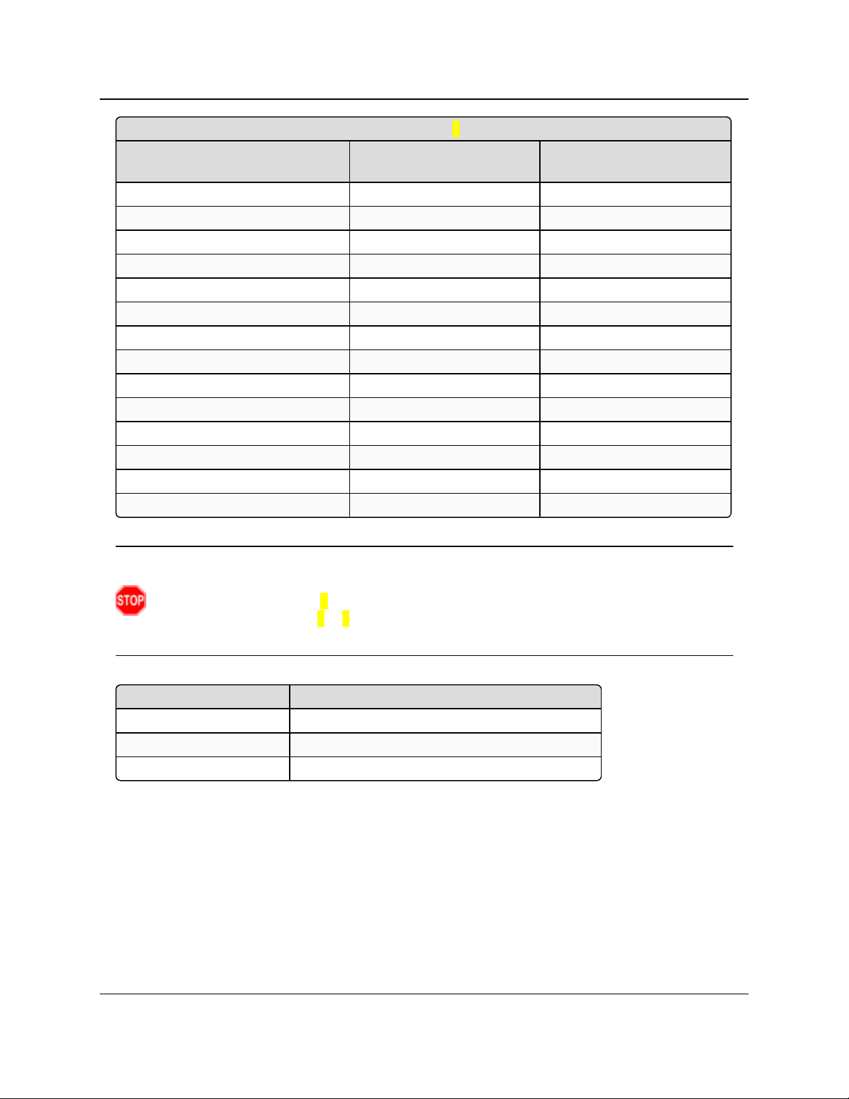
2.4GHz Frequency Zones (using Frequency Offset 0)
Binary Zone Number
(LSB First)
Beginning Freq.
(MHz)
Ending Freq.
(MHz)
0 2400.6528 2405.4912
1 2405.8368 2410.6752
2.4.2. 2.4GHz Frequency Zones
GX-C, GX-CE, GX-T
User & Reference Manual
2.4GHz Frequency Zones Table
This 2.4GHz Frequency Zone table shows the beginning frequency and ending frequency in
each of the 16 zones.
Note: The table reflects the usage of Frequency Offset 0.
Using Frequency Offset 1 or 2 shifts all frequencies by 115.2 or 230.4 kHz respectively.
LUM0034AA Rev May-2018 Page 43 of 126 Copyright © 2018FreeWave
This document is the property of FreeWave Technologies, Inc. and contains proprietary information owned by
FreeWave. This document cannot be reproduced in whole or in part by any means without written permission from
FreeWave Technologies, Inc.
Page 44
2. Basic Radio Programming and Setup
2.4GHz Frequency Zones (using Frequency Offset 0)
Binary Zone Number
(LSB First)
Beginning Freq.
(MHz)
Ending Freq.
(MHz)
2 2411.0208 2415.8592
3 2416.2048 2421.0432
4 2421.3888 2426.2272
5 2426.5728 2431.4112
6 2431.7568 2436.5952
7 2436.9408 2441.7792
8 2442.1248 2446.9632
9 2447.3088 2452.1472
10 2452.4928 2457.3312
11 2457.6768 2462.5152
12 2462.8608 2467.6992
13 2468.0448 2472.8832
14 2473.2288 2478.0672
15 2478.4128 2483.2512
Frequency Offset Frequency Zone Requirements
0 0xxxxxxxxxxxxxxx
1 xxxxxxxxxxxxxxx0
2 xxxxxxxxxxxxxxx0
GX-C, GX-CE, GX-T
User & Reference Manual
Warning! To adhere to the European Union specifications, it is necessary to use the proper
frequency zone combination based on the frequency offset.
Using a frequency offset of 0, the first zone (0) needs to be removed.
Using frequency offsets of 1 or 2 , the last zone (15) needs to be removed.
See ETSI TDMA Compliance (on page 112).
Enable Frequency Zones in Tool Suite
1. In the Tool Suite Configuration application, select the device to program.
2. Click the (3) Transmission Characteristics tab.
3. Click Frequency Zones to view the available frequency zones.
4. Select the Frequency Zones to enable.
LUM0034AA Rev May-2018 Page 44 of 126 Copyright © 2018FreeWave
This document is the property of FreeWave Technologies, Inc. and contains proprietary information owned by
FreeWave. This document cannot be reproduced in whole or in part by any means without written permission from
FreeWave Technologies, Inc.
Page 45

2. Basic Radio Programming and Setup
2.4GHz Government Rules
Setting Description
Default Setting The government rule is set at the factory to comply with the rules of the country
the radio is shipped to.
GX-C, GX-CE, GX-T
User & Reference Manual
Enable Frequency Zones using the Terminal Interface
1. On the main Setup menu, select 3 Edit Radio Transmission Characteristics.
2. Select option 0 FreqKey.
3. Select F for More.
4. Select option 3 Frequency Zone.
5. Enter:
1 to enable a frequency zone or
0 to disable a frequency zone.
Note: Frequency Zone entries begin with 0 (LSB) and continue through 15 (MSB).
Figure 12: HyperTerminal window with Frequency Zones
2.4.3. 2.4GHzGovernment Rules
LUM0034AA Rev May-2018 Page 45 of 126 Copyright © 2018FreeWave
This document is the property of FreeWave Technologies, Inc. and contains proprietary information owned by
FreeWave. This document cannot be reproduced in whole or in part by any means without written permission from
FreeWave Technologies, Inc.
Page 46

2. Basic Radio Programming and Setup
2.4GHz Government Rules
Setting Description
Options l (0) FCC rules - Power output can be set to a maximum of 27dBm (500mW)
l (1) ETSI 328 - Power output can be set to a maximum of 20dBm (100mW)
l See ETSI TDMA Compliance (on page 112) for additional information.
Terminal Menu (3) Edit Radio TransmissionCharacteristics > (0) FreqKey > F > (4) Government
Rules
Description: Sets the radio to comply with the government standards of the country the radio is
shipped to.
Note: The radio always uses the factory setting.
2.4GHz Hop Table Size
Setting Description
Default Setting 80
Options 75 to 80
Terminal Menu (3) Edit Radio TransmissionCharacteristics > (0) FreqKey > F > (1) Hop Table
Size
Description: Defines how many separate channels a given network uses.
FREEWAVE Recommends: Use the Frequency Zones instead of the
Hop Table Size setting.
2.4.4. High Noise
Note: This setting is not supported in the GX-C, GX-CE, GX-T radios.
GX-C, GX-CE, GX-T
User & Reference Manual
2.4.5. 2.4GHz Hop Frequency Offset
Important!: FreeWave internal use only.
2.4.6. 2.4GHz Hop Table Size
Note: All radios in a network must have identical Hop Table settings to function properly.
Warning! FCC regulations require a minimum of 75 separate frequency channels be used
within a hop pattern.
LUM0034AA Rev May-2018 Page 46 of 126 Copyright © 2018FreeWave
This document is the property of FreeWave Technologies, Inc. and contains proprietary information owned by
FreeWave. This document cannot be reproduced in whole or in part by any means without written permission from
FreeWave Technologies, Inc.
Page 47

2. Basic Radio Programming and Setup
2.4GHz Hop Table Version
Setting Description
Default Setting 2400 - 2483 MHz
Options l 2400 – 2483 MHz
l (2.4 - 2.4835 GHz)
Terminal Menu (3) Edit Radio TransmissionCharacteristics > (0) FreqKey > F > (0) Hop Table
Version
Description: Determines the section of the 2.4 GHz band the radio uses.
In the terminal interface, enter the number that corresponds to the frequency
band:
Number
to Enter
Frequency
Band
Description
0 2400 – 2483
MHz
(2.4 – 2.4835
GHz)
Entire band except for offset frequencies.
1 2400(46) – 2483
(54)MHz
Entire band except for offset frequencies.
2 2400(46) – 2427
(27)MHz
Lower 1/3 of the band.
3 2428(49) – 2455
(51)MHz
Middle of the band.
4 2456(51) – 2483
(54)MHz
Upper 1/3 of the band.
5 2428(49) – 2455
(51)MHz
2 outer 1/3 of band, avoids the middle
User & Reference Manual
2.4.7. 2.4GHz Hop Table Version
Note: All radios in a network must have identical Hop Table settings to function properly.
GX-C, GX-CE, GX-T
2.4.8. Max Packet Size and Min Packet Size (Golden Setting)
Note: In MultiPoint networks, the Max Packet Size and Min Packet Size must be set identically in
all radios.
In Point-to-Point networks the Master radio's settings take precedence over the Slave radio.
LUM0034AA Rev May-2018 Page 47 of 126 Copyright © 2018FreeWave
This document is the property of FreeWave Technologies, Inc. and contains proprietary information owned by
FreeWave. This document cannot be reproduced in whole or in part by any means without written permission from
FreeWave Technologies, Inc.
Page 48

2. Basic Radio Programming and Setup
Max Packet Size and Min Packet Size (Golden Setting)
Setting Description
Default Setting l Max Packet Size = 8
l Min Packet Size = 9
Options Any number between 0 and 9.
Terminal Menu (3) Edit TransmissionCharacteristics > (1) Max Packet Size and (2) Min
Packet Size
Description: The Max and Min Packet Size parameter settings and the RF Data Rate
parameter determine the number of bytes in the packets.
l Throughput can be enhanced when packet sizes are optimized.
l In Point-to-Point mode, the Max and Min Packet Size settings do not have
material impact on throughput unless 115.2 kbps is desired.
l However, this may have an impact on latency.
Example: If small amounts of data are sent and large packet sizes are
selected, a certain amount of time wasted between each packet would be
seen.
l In each over-the-air frame, both the Master and Slave are guaranteed the
number of bytes specified in the Minimum Packet Size parameter.
l In the Master, this is used for maintaining the RF link whether the Gateway
has data to transmit or not.
l The Maximum Packet Size parameter is used to allocate the maximum
number of bytes for each Master transmission.
l The Minimum Packet Size parameter is used to allocate the minimum
number of bytes for each Slave transmission.
l If the Master does not use all the bytes allocated in the Maximum Packet
Size setting minus the Minimum Packet Size setting, then the remaining
bytes are available for the Slave.
MCU Speed
Setting Description
Default Setting (0) Normal
GX-C, GX-CE, GX-T
User & Reference Manual
2.4.9. MCU Speed
LUM0034AA Rev May-2018 Page 48 of 126 Copyright © 2018FreeWave
This document is the property of FreeWave Technologies, Inc. and contains proprietary information owned by
FreeWave. This document cannot be reproduced in whole or in part by any means without written permission from
FreeWave Technologies, Inc.
Page 49

2. Basic Radio Programming and Setup
MCU Speed
Setting Description
Options l (0) Normal (low speed) - Reduces current consumption.
l (1) Fast (high speed) - Required for 230 KBaud and greater data port rate.
Note: If the radio is AES enabled and using the encryption functionality,
set this parameter to 3 using the terminal interface.
The value is accepted even though it is not viewable as an option and
applies only when using AES encryption.
For more information about setting up AES encryption, see Enable and Set
Up AES Encryption (on page 88).
Terminal Menu (3) Edit RadioTransmission Characteristics > (B) MCU Speed
Description: Controls the speed of the Micro Controller Unit (MCU) in the radio.
Remote LED
Setting Description
Default Setting (0) Local Only
Options l (0) Local Only - Only the LEDs on the board are enabled.
l (1) Remote and Local - LEDs on the board and remote LEDs through the
diagnostic port are enabled.
l (2) Remote Only - LEDs on the board are disabled. Remote LEDs through the
diagnostic port are enabled.
Terminal Menu (3) Edit Radio TransmissionCharacteristics > (C) Remote LED
Description:
Note: If using a GX radio with the optional 24-pin connector, use this option
to connect remote LEDs through the diagnostics port.
This feature may be used to save power in MultiPoint Repeaters.
l By turning off the on-board LEDs (setting = 2) the current consumption is
reduced.
l To reduce current consumption in Slave radios, use Low Power Mode
(setting = 1).
l Low Power Mode does NOT work with MultiPoint Repeaters because
Repeaters are constantly transmitting.
l Remote LED drives the Diagnostic port, which has a small amount of current
draw.
l When using remote LEDs, the center (TX) LED does NOT output a signal for a
green LED when in Setup mode.
l The Green TX LED has no remote pinout.
2.4.10. Remote LED
GX-C, GX-CE, GX-T
User & Reference Manual
LUM0034AA Rev May-2018 Page 49 of 126 Copyright © 2018FreeWave
This document is the property of FreeWave Technologies, Inc. and contains proprietary information owned by
FreeWave. This document cannot be reproduced in whole or in part by any means without written permission from
FreeWave Technologies, Inc.
Page 50

2. Basic Radio Programming and Setup
Retry Time Out
Setting Description
Default Setting 255
Options Any number between 0 and 255 in MultiPoint networks.
Note: The minimum in 900MHz radios is 8 seconds.
Any number between 151 and 255 in Point-to-Point networks.
Terminal Menu (3) Edit Transmission Characteristics > (8) RetryTime Out
Description: The Retry Time Out parameter in a Slave or Repeater sets the delay the unit
waits before dropping the connection to a Master or Repeater.
l The factory default is set at the maximum of 255.
l With a setting of 255, the Master allows a Slave or Repeater to stay
connected as long as 1 packet in 255 is successfully received at the
Master.
l The maximum setting means that if 1packet in 255is sent successfully from
the Master to the Slave or Repeater, the link is maintained.
l This allows a Slave or Repeater to drop a connection if less than 1 in 8
consecutive packets is successfully received from the Master.
The Retry Time Out parameter is useful when a MultiPoint network has a roving
Master or Slave. As the link gets weaker, a lower setting allows a poor link to
break in search of a stronger one.
FREEWAVE Recommends: Setting the Retry Time Out parameter to
20 in the MultiPoint Master is recommended in areas where several
FreeWave networks exist.
This recommended setting allows Slaves and Repeaters to drop the
connection if the link becomes too weak, while at the same time prevent
errant disconnects due to interference from neighboring networks.
Note: While intended primarily for MultiPoint networks, the Retry Time
Out parameter may be changed in Point-to-Point networks.
However, the value in Point-to-Point mode should NOT be set to less than
151.
2.4.11. Retry Time Out
GX-C, GX-CE, GX-T
User & Reference Manual
LUM0034AA Rev May-2018 Page 50 of 126 Copyright © 2018FreeWave
This document is the property of FreeWave Technologies, Inc. and contains proprietary information owned by
FreeWave. This document cannot be reproduced in whole or in part by any means without written permission from
FreeWave Technologies, Inc.
Page 51

2. Basic Radio Programming and Setup
RF Data Rate (Golden Setting)
Setting Description
Default Setting (3) Normal
Options l (2) High - 153.6 kbps
l (3) Normal - 115.2 kbps
Terminal Menu (3) Edit Transmission Characteristics > (4)RF Data Rate
Description:
Important!: Do NOT confuse the RF Data Rate with the serial port Baud
Rate.
FreeWave radios have these RF Data Rate settings:
l 2 (High).
l Use setting 2 (RF Speed of 153.6 kbps) when the radios are close together
and need to optimize data throughput.
l 3 (Normal).
l Use setting 3 (RF Speed of 115.2 kbps) when the radios are farther away
and a solid data link is preferred over data throughput.
Slave Security
Setting Description
Default Setting (0) On
Options (0) On
(1) Off
Terminal Menu (3) Edit TransmissionCharacteristics > (6) Slave Security
GX-C, GX-CE, GX-T
User & Reference Manual
2.4.12. RF Data Rate (Golden Setting)
Note: In MultiPoint networks, the RF Data Rate parameter must be set the same in all radios. Any
radio with an RF Data Rate setting different from the Master will not establish a link. In Point-toPoint networks the Master setting takes precedence over the Slave.
2.4.13. Slave Security
Note: The Slave Security parameter has no effect in Point-to-MultiPoint networks where the
Network ID is used.
LUM0034AA Rev May-2018 Page 51 of 126 Copyright © 2018FreeWave
This document is the property of FreeWave Technologies, Inc. and contains proprietary information owned by
FreeWave. This document cannot be reproduced in whole or in part by any means without written permission from
FreeWave Technologies, Inc.
Page 52

2. Basic Radio Programming and Setup
Slave Security
Setting Description
Description: l Slave Security allows Slave radios to accept transmissions from a Master not
included in the Call Book.
l The default setting of 0 (On) means only Masters in the Slave radio's Call
Book may link to that Slave.
l The Slave Security parameter may be disabled (setting of 1) allowing any
Master to call the Slave.
l The Slave Security parameter must be set to 1 when the unit is operating in
Mode 6, Slave/Master Switchable or a Point-to-Point network where the Slave
may need to accept calls from more than 10 different Masters.
l See Application Note #5476: Mode 6 for additional information.
l When the Slave Security parameter is set to 1, the radio accepts calls from
any other radio.
l Additional network security measures may be taken to prevent unauthorized
access (e.g., changing default settings for Frequency Key, Hop Table, or
Frequency Zones).
Transmit Power
Setting Description
Default Setting 20
Options Any number between 0 and 27
Terminal Menu (3)Edit Transmission Characteristics > (5) RFXmit Power
Description: Sets the output power of the radio in dBm.
Settings range from 0dBm (1mW) to 27dBm (500mW).
The maximum value may be capped at 20 dBm at the factory to comply with ETSI
regulations, or capped at other values to comply with country-specific
requirements.
Note: See ETSI TDMA Compliance (on page 112) for more information.
When testing radios, and they are in close proximity to one another,
set the Transmit Power parameter to a low number.
When deploying radios to the field, raise the Transmit Power
number accordingly.
GX-C, GX-CE, GX-T
User & Reference Manual
2.4.14. Transmit Power
FreeWave. This document cannot be reproduced in whole or in part by any means without written permission from
Important!: This table is for reference only. AllTransmit Power settings below 9 are approximate.
LUM0034AA Rev May-2018 Page 52 of 126 Copyright © 2018FreeWave
This document is the property of FreeWave Technologies, Inc. and contains proprietary information owned by
FreeWave Technologies, Inc.
Page 53

2. Basic Radio Programming and Setup
Transmit Rate
Setting Description
Default Setting (1) Normal
Options l 0 - Diagnostics
l 1 - Normal
Terminal Menu (3) Edit TransmissionCharacteristics > (3) Xmit Rate
Description: GX-C, GX-CE, GX-T radios have two available Transmit Rate settings.
l The setting for normal operation of the radio is 1.
l When set to 0, the radios transmit back and forth continuously regardless if
they have any actual data.
l 0 should be used only as a diagnostic tool and not for normal operation.
l The strength of the signal may be gauged by the Clear to Send (CTS) LED.
l A solid red ( ) CTS LED indicates a strong signal.
l A blinking ( ) CTS LED indicates a weaker signal.
0 is useful to qualitatively gauge signal strength in Point-to-Point mode.
2.4.15. Transmit Rate
GX-C, GX-CE, GX-T
User & Reference Manual
LUM0034AA Rev May-2018 Page 53 of 126 Copyright © 2018FreeWave
This document is the property of FreeWave Technologies, Inc. and contains proprietary information owned by
FreeWave. This document cannot be reproduced in whole or in part by any means without written permission from
FreeWave Technologies, Inc.
Page 54

GX-C, GX-CE, GX-T
User & Reference Manual
3. Configuring
Point-to-MultiPoint Networks
When installing MultiPoint networks it is important to do some up front planning around the
devices to implement and the route the data is going to take back to the Master. A MultiPoint
network can contain the following devices:
l Only one Master. All communications are from and to the Master.
l An unlimited number of Slave radios (remote sites).
l An unlimited number of Repeaters between any Slave and the Master.
l Serial Repeaters can be Slave radios and Repeaters at the same time.
This section provides details about the setup that applies specifically to a MultiPoint network:
l Point to MultiPoint network characteristics.
l Using the Network ID or the Call Book to establish which radios in the network can
communicate with each other.
l Using subnet IDs to route traffic through the network, back to the Master.
l Settings and recommendations for additional parameters that apply to a MultiPoint
network.
l Conserving power in devices within the network.
l Running network diagnostics.
Note: See Routing Communications through the Network (on page 98) and Assigning Subnet ID
Values (on page 98) for additional information.
LUM0034AA Rev May-2018 Page 54 of 126 Copyright © 2018FreeWave
This document is the property of FreeWave Technologies, Inc. and contains proprietary information owned by
FreeWave. This document cannot be reproduced in whole or in part by any means without written permission from
FreeWave Technologies, Inc.
Page 55

3. Configuring Point-to-MultiPoint Networks
GX-C, GX-CE, GX-T
User & Reference Manual
3.1. Point to MultiPoint Network Characteristics
A Point to MultiPoint network has these unique characteristics:
l Golden Settings (on page 55).
l Master to Slave Communications (on page 55).
l Slave to Master Communications (on page 55).
3.1.1. Golden Settings
A Point-to-MultiPoint network requires that the Golden Settings (described in Golden Settings (on
page 41)) are set the same on ALL radios in the network.
If several independent MultiPoint networks are located in close proximity, the planning becomes
more critical. It is very important to include as much frequency and time diversity as possible using
different Min and Max Packet Size. In some instances the use of the MultiMaster Sync option
may be required.
In almost all MultiPoint networks, the Frequency Key is the same for all radios. In other networks,
where parallel Repeaters are introduced, the Frequency Key value needs to change.
3.1.2. Master to Slave Communications
Master - to - Slave communications within a MultiPoint network have these characteristics:
l Data packets sent from the Master include a 32-bit CRC.
l The Master repeats its data broadcast between 0 to 9 times, depending on the Master
Packet Repeat setting. For more information, see Master Packet Repeat (on page 66).
l A Slave or Repeater does not send acknowledgments to the Master when it receives data.
l When any Slave in the network receives the data packet from the Master with the 32-bit
CRC, that Slave ignores any additional repeats of the data, and passes the data to its
data port.
l Repeaters in the network send data to Slave radios and other Repeaters.
3.1.3. Slave to Master Communications
Slave - to - Master communications within a MultiPoint network have these characteristics:
l Data packets sent from the Slave to the Master include a 32-bit CRC.
l When the Master successfully receives data, it sends an acknowledgment to the Slave and
passes the data out its data port.
LUM0034AA Rev May-2018 Page 55 of 126 Copyright © 2018FreeWave
This document is the property of FreeWave Technologies, Inc. and contains proprietary information owned by
FreeWave. This document cannot be reproduced in whole or in part by any means without written permission from
FreeWave Technologies, Inc.
Page 56

3. Configuring Point-to-MultiPoint Networks
GX-C, GX-CE, GX-T
User & Reference Manual
3.2. Point-to-MultiPoint Network Quick Start
This is a quick start procedure for setting up two radios in Point-to-MultiPoint mode. This mode
allows for a Master to communicate with several Repeaters and Slaves simultaneously.
3.2.1. Point-to-MultiPoint Network Quick Start (Tool Suite)
1. Connect the radio to the serial port of a computer using either a serial cable or the
diagnostics cable.
2. Connect the radio to a power source.
Important!: Power supply ranges and recommendations vary depending on model.
Verify the specifications for the model prior to connecting power.
3. Open a Tool Suite session.
4. Click the Configuration application.
5. Verify the correct port is selected in the Com Port field in the upper left of the
Configuration ribbon.
6. On the Configuration ribbon, in the Network section, click the network the radio resides in
or
Click Add Network to create a new network in Tool Suite.
7. Click Read Radio on the Configuration ribbon to read the radio's current settings.
l If using a diagnostics cable to connect to the radio, the radio automatically goes into
Setup mode.
l When in Setup mode, all three LEDs on the radio are solid green.
l If using a data cable to connect to the radio, follow the prompt to press the radio's
Setup button to put it in Setup mode.
8. Click the Operation Mode tab.
9. In the Modem Mode field:
Select 2 to set the radio as a Point-to-MultiPoint Master.
Select 3 to set the radio as a Point-to-MultiPoint Slave.
Note: A MultiPoint network can have only one Master, unless running in Multi-Master Sync
mode.
For more information, see Multi-Master Sync (on page 93).
10. Click the Baud Rate tab.
11. Change the Baud Rate, Data Parity, and Modbus RTU to match the device that the radio
is to be connected to.
12. Click the Transmission Characteristics tab.
13. Set these parameters so they are identical on all radios in the network:
l Frequency Key
l Max Packet Size
LUM0034AA Rev May-2018 Page 56 of 126 Copyright © 2018FreeWave
This document is the property of FreeWave Technologies, Inc. and contains proprietary information owned by
FreeWave. This document cannot be reproduced in whole or in part by any means without written permission from
FreeWave Technologies, Inc.
Page 57

3. Configuring Point-to-MultiPoint Networks
l Min Packet Size
l RF Data Rate
Note: If several independent MultiPoint networks are located in close proximity, it is very
important to include as much frequency and time diversity as possible through use of different
Frequency Key, Min and Max Packet Size, and Hop Table settings.
14. Click the MultiPoint Parameters tab.
15. In the Network ID field, set to any value between 1 and 4095.
FREEWAVE Recommends: Set the Network ID to the last three or four digits of the Master
radio's serial number if it is below 4095.
This value must be the same in all radios in the network.
Important!: A setting of 255 disables the Network ID feature and enables the Call Book.
16. Send the parameter settings by either:
l Sending all the settings for all parameters:
In the Configuration application, on the Network Title ribbon, click All.
l Sending only the changed parameters:
In the Configuration application, on the Network Title ribbon, click Quick.
GX-C, GX-CE, GX-T
User & Reference Manual
Note: This option is only available if Read Radio is clicked and parameter settings are
NOT sent from a template to the radio.
3.2.2. Point-to-MultiPoint Network Quick Start (Terminal Interface)
1. Connect the radio to the serial port of a computer using either a serial cable or the
diagnostics cable.
2. Connect the radio to a power source.
Important!: Power supply ranges and recommendations vary depending on model.
Verify the specifications for the model prior to connecting power.
3. Open a terminal emulator session.
Use the Tool Suite Setup Terminal application if a terminal emulator is not available.
4. Connect to COMx (where 'x' is the number of the COM connected port).
5. Set these options:
l Data Rate: 19,200
l Data Bits: 8
l Parity: None
LUM0034AA Rev May-2018 Page 57 of 126 Copyright © 2018FreeWave
This document is the property of FreeWave Technologies, Inc. and contains proprietary information owned by
FreeWave. This document cannot be reproduced in whole or in part by any means without written permission from
FreeWave Technologies, Inc.
Page 58

3. Configuring Point-to-MultiPoint Networks
l Stop Bits: 1
l Flow Control: None
GX-C, GX-CE, GX-T
User & Reference Manual
6. Press the Setup button on the radio.
If using the diagnostics cable, press <Shift+U>.
l The three LEDs on the radio should all turn green , indicating Setup mode.
l The Main menu appears on the screen.
7. Press <0> to access the Operation Mode menu.
8. Press <2> to set the radio as a Point-to-MultiPoint Master or
Press <3> to set the radio as a Point-to-MultiPoint Slave.
9. Press <Esc> to return to the Main menu.
Note: A MultiPoint network can have only one Master, unless running in Multi-Master Sync
mode.
For more information, see Multi-Master Sync (on page 93).
10. Press <1> on the Main menu.
11. Change the Baud Rate, Data Parity, and Modbus RTU to match the device that the
radio is to be attached to.
12. Press <Esc> to return to the Main menu.
13. Press <3> in the Main menu.
14. Set these parameters so they are the same on all radios in the network:
l FreqKey
l Max Packet Size
l Min Packet Size
l RF Data Rate
Note: The Frequency Key option is located in the F submenu after pressing 0 to access the
Frequency Key menu in Main menu 3.
15. Press <Esc> to return to the Main menu.
16. Press <5> on the Main menu.
17. In the Network ID field, set the value to any value between 1 and 4095.
Note: A 255 setting disables the Network ID feature and enables the Call Book.
FREEWAVE Recommends: Set the Network ID to the last three or four digits of the Master
radio's serial number if it is below 4095.
This value must be the same in all radios in the network.
18. Press <Esc> to exit the Setup menu and resume normal radio operation.
LUM0034AA Rev May-2018 Page 58 of 126 Copyright © 2018FreeWave
This document is the property of FreeWave Technologies, Inc. and contains proprietary information owned by
FreeWave. This document cannot be reproduced in whole or in part by any means without written permission from
FreeWave Technologies, Inc.
Page 59

Master Slave Repeater
Con dit ion
Carrier
Detect
(CD)
Transmit
(Tx)
Clear to
Send
(CTS)
Carrier
Detect
(CD)
Transmit
(Tx)
Clear to
Send
(CTS)
Carrier
Detect
(CD)
Transmit
(Tx)
Clear to
Send
(CTS)
Powered, not linked Solidred
bright
Solid red
dim
Off
Solid red
bright
Off
Blinking
red
Solid red
bright
Off
Blinking
red
Repeater and Slave linked to
Master.
No data.
Solid red
bright
Solid red
dim
Off
Solid
green
Off
Solid red
bright
Solid
green
Solid red
dim
Solid red
bright
Repeater and Slave linked to
Master.
Master sending data to
Slave.
Solid red
bright
Solid red
dim
Off
Solid
green
Off
Solid red
bright
Solid
green
Solid red
dim
Solid red
bright
Repeater and Slave linked to
Master.
Slave sending data to
Master.
Solid green RCV data
or Solid red
bright
Solid red
dim
Intermittent
flash red
Solid
green
Intermittent
flash red
Solid red
bright
Solid
green
Solid red
bright
Solid red
bright
Master with diagnostics
program running.
Solid red
bright
Solid red
dim
Intermittent
flash red
Solid
green
Intermittent
flash red
Solid red
bright
Solid
green
Solid red
bright
Solid red
bright
3. Configuring Point-to-MultiPoint Networks GX-C, GX-CE, GX-T User & Reference Manual
3.3. Point-to-MultiPoint Operation LEDs
Note: *In an idle condition, the CTS LED is solid red with a solid link, as the link weakens the CTS LED on the Repeater and Slave begins
to blink .
LUM0034AA Rev May-2018 Page 59 of 126 Copyright © 2018FreeWave
This document is the property of FreeWave Technologies, Inc. and contains proprietary information owned by FreeWave. This document cannot be reproduced
in whole or in part by any means without written permission from FreeWave Technologies, Inc.
Page 60

3. Configuring Point-to-MultiPoint Networks
GX-C, GX-CE, GX-T
User & Reference Manual
3.4. Overlapping MultiPoint Networks
Overlapping MultiPoint networks may be set up effectively when several key parameters are set
correctly. Overlapping MultiPoint networks are defined as networks using different Master radios,
which share or overlap in a specific geographic area. It may also include collocated radios
configured into different networks.
For more information, see Application Note #5412, Synchronizing Collocated Masters (Multi-
Master Sync Mode) (available from www.freewave.com).
Collocated MultiPoint networks require these parameters be unique for each network:
l Network ID (unless using the Call Book)
l Frequency Key (with Repeater Frequency)
l Max Packet Size
l Min Packet Size
Note: For more information about the installation of Point-to-MultiPoint networks, contact FreeWave
Technical Support.
See Contact FreeWave Technical Support on page 9
3.5. Establishing Communication with Other Radios in a MultiPoint Network
For the radios in the network to communicate successfully, the radio needs to know what other
devices are available for them to communicate with. Use the Network ID or the Call Book.
FREEWAVE Recommends: While the Call Book is an option in Point-to-MultiPoint networks,
FreeWave strongly recommends using the Network ID feature in most applications.
If a large MultiPoint network is implemented using the Call Book and a radio needs to be added to or
replaced in the network, each radio in the network must be physically reprogrammed and the new
serial number entered in the radio's Call Book.
This can be a time consuming process and can cause a delay in getting the network back up and
running.
Because the Network ID does not use serial numbers, MultiPoint Master radios and Repeaters may
be added or replaced without reprogramming each Slave radio in the network.
3.5.1. Using the Network ID in MultiPoint Networks
The Network ID parameter is located on the MultiPoint Parameters tab. In a single network,
assign each radio the same Network ID. Slave radios link with the first Master or Repeater it
hears that has a matching Network ID.
When setting the Network ID:
l The value can be any value between 1 and 4095, except 255.
l 255 enables the Call Book.
LUM0034AA Rev May-2018 Page 60 of 126 Copyright © 2018FreeWave
This document is the property of FreeWave Technologies, Inc. and contains proprietary information owned by
FreeWave. This document cannot be reproduced in whole or in part by any means without written permission from
FreeWave Technologies, Inc.
Page 61

3. Configuring Point-to-MultiPoint Networks
Entry Number Repeater 1 Repeater 2
(0) 000-0000
(1) 000-0000
l To help ensure the ID is unique to the network, avoid using numbers that coincide with
GX-C, GX-CE, GX-T
User & Reference Manual
nearby landmarks or highways.
Example: Use the last four digits of the Master serial number if it is below 4095.
This is ensured to be unique and does not overlap with other nearby FreeWave networks.
l Use the Network ID function in conjunction with the Subnet ID feature (if necessary) to
route data through the radio network.
3.5.2. Using the Call Book in MultiPoint Networks
Although NOT recommended, the Call Book is an option in MultiPoint networks. If the Network
ID feature is used in a MultiPoint network, no entries are needed in the Call Book of any of the
radios.
FREEWAVE Recommends: While the Call Book is an option in Point-to-MultiPoint networks,
FreeWave strongly recommends using the Network ID feature in most applications.
If a large MultiPoint network is implemented using the Call Book and a radio needs to be added to or
replaced in the network, each radio in the network must be physically reprogrammed and the new
serial number entered in the radio's Call Book.
This can be a time consuming process and can cause a delay in getting the network back up and
running.
Because the Network ID does not use serial numbers, MultiPoint Master radios and Repeaters may
be added or replaced without reprogramming each Slave radio in the network.
Important!: Using the Call Book in a MultiPoint network can cause delay in resuming
communications if a Master is damaged.
Note: For information about setting the Call Book, see Using the Call Book in Point-to-Point
Networks on page 80.
In a MultiPoint network, the Slave radios and Repeaters are not listed in the Master radio's Call
Book. Slave radios must have the Master and any Repeater it is going to use in its Call Book.
These examples show the Call Book of a MultiPoint network comprised of a Master, Repeater,
and Slave in which the Slave can communicate either through the Repeater or directly to the
Master.
MultiPoint Master Call Book (Unit Serial Number 900-0001)
Note: No serial number entries are necessary in the Master’s Call Book.
LUM0034AA Rev May-2018 Page 61 of 126 Copyright © 2018FreeWave
This document is the property of FreeWave Technologies, Inc. and contains proprietary information owned by
FreeWave. This document cannot be reproduced in whole or in part by any means without written permission from
FreeWave Technologies, Inc.
Page 62

3. Configuring Point-to-MultiPoint Networks
Entry Number Repeater 1 Repeater 2
(0) 900-0001
(1) 000-0000
Entry Number Repeater 1 Repeater 2
(0) 900-0001
(1) 900-0002
(2) 000-0000
MultiPoint Repeater Call Book (Unit Serial Number 900-0002)
MultiPoint Slave Call Book (Unit Serial Number 900-0003)
At times, the Slave radios need to be forced to go through a specific MultiPoint Repeater.
In this scenario, the Slave radio's Call Book should contain only the serial number for that
Repeater as the entry on line 0.
GX-C, GX-CE, GX-T
User & Reference Manual
3.5.3. Programming Point-to-MultiPoint Extended Call Book
In a MultiPoint network, Slave radios can be programmed to roam between Master radios and
Repeaters using the MultiPoint Extended Call Book function. Slave radios with Call Book, as
configured in this procedure, communicate with any radio whose serial number appears in any of
the three columns.
Procedure
1. Set the Network ID to 255.
2. In the Call Book, enter 999-9999 as the last entry in the first and second columns.
3. In the Call Book, set Entry to Call to All.
Figure 13: HyperTerminal PTMP Extended Call Book
LUM0034AA Rev May-2018 Page 62 of 126 Copyright © 2018FreeWave
This document is the property of FreeWave Technologies, Inc. and contains proprietary information owned by
FreeWave. This document cannot be reproduced in whole or in part by any means without written permission from
FreeWave Technologies, Inc.
Page 63

3. Configuring Point-to-MultiPoint Networks
1 PPS Enable Delay
Setting Description
Default Setting 255
Options l 255 to disable 1 PPS
l 0 to 254 to enter the delay
Terminal Menu (5) Edit MultiPoint Parameters > (9) 1 PPS Enable/Delay
Description: The 1 PPS Enable/Delay setting allows a 1PPS signal to propagate from the
Master to all Slave in a MultiPoint network.
When this parameter is enabled a properly generated pulse applied on the DTR
line of the Master provides a 1 PPS pulse on the CD line of any Slave in the
network.
GX-C, GX-CE, GX-T
User & Reference Manual
3.6. Setting Other MultiPoint Parameters
The other MultiPoint Parameters options allow you to modify several different parameters in the
radio that determine the characteristics of a MultiPoint network.
l In Tool Suite, set these parameters in the MultiPoint Parameters tab.
l These settings are available in the MultiPoint Parameters menu in the terminal interface.
Note: See the Parameter Preference (on page 10) for a description of the parameter table's content.
3.6.1. 1 PPS Enable Delay
Important!: When 1 PPS is enabled, the Master radio must have a 1 PPS pulse on its DTR pin,
otherwise the RF network does not function.
Setup 1PPS Enable/Delay
1. On the Master radio, set the 1 PPS Enable/Delay parameter to 0.
Note: The Master must have a 1 PPS pulse on the DTR pin, otherwise the RF network will
not function.
2. Enable the 1 PPS Enable/Delay parameter on the Slave radios.
Slave radios are calibrated at the factory.
LUM0034AA Rev May-2018 Page 63 of 126 Copyright © 2018FreeWave
This document is the property of FreeWave Technologies, Inc. and contains proprietary information owned by
FreeWave. This document cannot be reproduced in whole or in part by any means without written permission from
FreeWave Technologies, Inc.
Page 64

3. Configuring Point-to-MultiPoint Networks
Diagnostics
Setting Description
Default Setting 0 (Disabled)
Options Any number between 0 and 128
Terminal Menu (5) Edit MultiPoint Parameters > (B) Diagnostics
Description: Allows diagnostics data in the Network Diagnostics in Tool Suite to be viewed at
the Master radio in parallel with application data.
l The setting in this parameter determines how many slots out of 128 are
dedicated to diagnostics.
l Diagnostics is always secondary to actual transmitted data.
Example: If set to 10, 1 out of every 10 data slots is for diagnostics data.
If set to 100, 1 out of every 100 data slots is for diagnostics data.
Note: For more information, see Reading Diagnostics in Tool Suite on
page 73.
DTR Connect
Setting Description
Default Setting (0) Off
GX-C, GX-CE, GX-T
User & Reference Manual
Calibrate a Slave Radio in 1PPS Enable/Delay Mode
1. On the Master radio, trigger an oscilloscope on the 1 PPS pulse on the DTR line.
2. Monitor the CD line of the Slave radio.
3. If the timing on the Slave radio differs from the Master it may be adjusted via the value in the
Slave radio's 1 PPS Enable/Delay parameter.
The difference in time between each incremental integer value is 542.534 nanoseconds (ns).
Changing the parameter to higher values decreases the Slave radio time delay and changing the
parameter to lower values increases the time delay.
When properly calibrated, the CD line Slave radio outputs a pulse that goes high for about 2 ms in
sync with the 1 PPS pulse on the Master radio. The output on the Slave radio occurs within 20
microseconds of the input to the Master.
3.6.2. Diagnostics
3.6.3. DTR Connect
LUM0034AA Rev May-2018 Page 64 of 126 Copyright © 2018FreeWave
This document is the property of FreeWave Technologies, Inc. and contains proprietary information owned by
FreeWave. This document cannot be reproduced in whole or in part by any means without written permission from
FreeWave Technologies, Inc.
Page 65

3. Configuring Point-to-MultiPoint Networks
DTR Connect
Setting Description
Options l (0) Off - When set to off in the Slave radio, the radio transmits when the data is
received.
l (1) DTR Sensing - Forms a Point-to-Point link with the Master radio when the
DTR line is high to send data.
l (2) Burst Mode - The radio transmits data in bursts.
Terminal Menu (5) MultiPoint parameters > (4) DTR Connect
Description: Determines how the radio sends its data.
Note: This mode is valuable when a network has many low data rate
devices and to increase overall network capacity.
The radio has two separate transmit and receive user data buffers of 2kb each.
Caution: In case of a buffer overflow, the radio outputs unpredictable
data.
Local Mode
Setting Description
Default Setting (0) Disabled
Options (0) Disabled, (1) Enabled
Terminal Menu (5) Edit MultiPointParameters > (E) Local Access
Description: Enable Local Mode to access a Slave radio with a local Master radio.
Important!: This Master does NOT take the place of the network Master.
Note: For more information, see Application Note #5457, Local Mode
(available from www.freewave.com).
GX-C, GX-CE, GX-T
User & Reference Manual
3.6.4. Local Mode
LUM0034AA Rev May-2018 Page 65 of 126 Copyright © 2018FreeWave
This document is the property of FreeWave Technologies, Inc. and contains proprietary information owned by
FreeWave. This document cannot be reproduced in whole or in part by any means without written permission from
FreeWave Technologies, Inc.
Page 66

3. Configuring Point-to-MultiPoint Networks
Master Packet Repeat
Setting Description
Default Setting 3
Options Any number between 0 and 9.
Terminal Menu (5) Edit MultiPoint Parameters > (1) Master Packet Repeat
Description: In a Point-to-MultiPoint network, Slave radios do not acknowledge transmissions
from the Master.
l If Slave radios did acknowledge all data transmissions, in a large network, the
Master would soon become overwhelmed with acknowledgments from the
Slaves.
l Without acknowledgments, 100% confidence every Slave radio has received
every packet cannot be met.
l To address this issue, change the Master Packet Repeat parameter,
assigning a value between 0 (the packet is transmitted once) to 9 (the packet
is transmitted 10 times).
For networks with solid RF links, this parameter should be set to a low value (e.g.,
1 or 2).
l If a network has some weak or marginal links it should be set with higher
values.
l If a Slave radio receives a good packet from a Master more than once it
discards the repeated packets.
l Similarly, after a MultiPoint Repeater receives a good packet from the Master,
it discards any further repeated packets.
l In turn, the Repeater sends the packet out to the next Repeater or Slaves the
number of times corresponding to its own Master Packet Repeat setting.
Increasing the Master Packet Repeat setting increases the probability of a
packet getting through, but also increases latency in the network because each
packet from the Master or Repeater is being sent multiple times.
Note: Therefore, it is important to find the optimal mix between network
robustness, throughput, and latency.
In general, a setting of 2 to 3 works well for most well designed networks.
The Master Packet Repeat parameter may be set to 0 if the user software is
capable of, or requires acknowledgment.
In this case, if the Master sends a packet that the Slave radio does not receive,
the user software controls the retries as needed.
3.6.5. Master Packet Repeat
Note: When using the radio in Modbus RTU mode, the Master Packet Repeat setting must match
in every radio, regardless of whether the network is in Point-to-Point or MultiPoint mode.
GX-C, GX-CE, GX-T
User & Reference Manual
LUM0034AA Rev May-2018 Page 66 of 126 Copyright © 2018FreeWave
This document is the property of FreeWave Technologies, Inc. and contains proprietary information owned by
FreeWave. This document cannot be reproduced in whole or in part by any means without written permission from
FreeWave Technologies, Inc.
Page 67

3. Configuring Point-to-MultiPoint Networks
Max Slave Retry
Setting Description
Default Setting 9
Options Any number between 1 and 9.
Terminal Menu (5) Edit MultiPoint Parameters > (2) Max Slave Retry
Description: l Defines how many times the Slave radio attempts to retransmit a packet to the
Master before beginning to use a back-off algorithm as defined by the Retry
Odds on page 69 setting.
l The Slave radio retries stop when the Slave receives an acknowledgment from
the Master.
Radio ID
Setting Description
Default Setting Blank
Options Any 4 digit, user-defined number.
Terminal Menu (5) Edit MultiPoint Parameters > (D) Radio ID
Description: Use this option to designate a radio with an arbitrary, user-defined, 4-digit number
that identifies the radio in Diagnostics mode.
GX-C, GX-CE, GX-T
User & Reference Manual
3.6.6. Master Packet Repeat in MultiPoint Networks with Repeaters
The Master Packet Repeat parameter must be set in MultiPoint Repeaters because a Repeater
appears as a Master to a Slave radio.
Therefore, the Repeater sends the packet out the number of times corresponding to its own
Master Packet Repeat parameter setting. If this parameter is set improperly the reliability of the
overall network may be diminished.
Example: If a Master's Master Packet Repeat parameter setting is 3, the link between the Master
and Repeater should be robust.
If the Repeater's Master Packet Repeat parameter setting is 0, this could cause marginal links
between the Repeater and the Slaves.
The Slaves communicating through this Repeater only receive the initial packet from the Master with
no repeats.
Therefore, if the packet is not received on the first try, the Slave radio does not respond as expected.
Note: The Master Packet Repeat parameter setting in any MultiPoint Repeater must be less than
or equal to the Master's setting.
3.6.7. Max Slave Retry
3.6.8. Radio ID
LUM0034AA Rev May-2018 Page 67 of 126 Copyright © 2018FreeWave
This document is the property of FreeWave Technologies, Inc. and contains proprietary information owned by
FreeWave. This document cannot be reproduced in whole or in part by any means without written permission from
FreeWave Technologies, Inc.
Page 68

3. Configuring Point-to-MultiPoint Networks
Radio Name
Setting Description
Default Setting Blank
Options A maximum of 20 characters in any combination of letters or numbers.
Terminal Menu (5) Edit MultiPoint Parameters > (G) Radio Name
Description: Use this parameter to give a radio a name, such as its location.
Naming radios can be helpful to identify a radio when in
Diagnostics mode.
Repeater Frequency
Setting Description
Default Setting (0) Disabled
Options (0) Disabled
(1) Enabled
Terminal Menu (5) Edit MultiPoint Parameters > (5) Repeater Frequency
Description: Enable this parameter when a Frequency Key is needed other than that of the
Master.
l This condition occurs when parallel Repeaters in a network may have
overlapping areas of responsibility.
l The default setting of 0 (Disabled) causes the Repeater to use the key set in
the Frequency Key parameter on the Tool Suite Transmission
Characteristics tab.
Note: When the Repeater Frequency parameter is disabled and Subnets
are NOT configured, the Frequency Key parameter setting in eachSlave
radio MUST match the Master or Repeater acting as the Master for the
radio.
3.6.9. Radio Name
3.6.10. Repeater Frequency
GX-C, GX-CE, GX-T
User & Reference Manual
3.6.11. Repeaters
Note: This parameter needs to be set in the MultiPoint Master only.
The setting has no effect if set in a MultiPoint Slave.
LUM0034AA Rev May-2018 Page 68 of 126 Copyright © 2018FreeWave
This document is the property of FreeWave Technologies, Inc. and contains proprietary information owned by
FreeWave. This document cannot be reproduced in whole or in part by any means without written permission from
FreeWave Technologies, Inc.
Page 69

3. Configuring Point-to-MultiPoint Networks
Repeaters
Setting Description
Default Setting (1) Enabled
Options l 0 - Disabled
l 1 - Enabled
Terminal Menu (5) Edit MultiPoint Parameters > (0) Number Repeaters
Description: Indicates if any number of Repeaters exist in the network.
Retry Odds
Setting Description
Default Setting 0
Options Any number between 0 and 9.
Terminal Menu (5) Edit MultiPoint Parameters > (3) Retry Odds
3.6.12. Retry Odds
GX-C, GX-CE, GX-T
User & Reference Manual
LUM0034AA Rev May-2018 Page 69 of 126 Copyright © 2018FreeWave
This document is the property of FreeWave Technologies, Inc. and contains proprietary information owned by
FreeWave. This document cannot be reproduced in whole or in part by any means without written permission from
FreeWave Technologies, Inc.
Page 70

3. Configuring Point-to-MultiPoint Networks
Retry Odds
Setting Description
Description: While packets transmitted from the Master to the Slave radios in a MultiPoint
network are not acknowledged, packets transmitted from Slaves to the Master are
acknowledged.
It is possible that more than one Slave attempts to transmit to the Master at the
same time. Therefore, it is important that a protocol exists to resolve contention
for the Master between Slaves in the network.
This is addressed through the Max Slave Retry (on page 67) and Retry Odds
parameters.
l After the Slave has unsuccessfully attempted to transmit the packet the
number of times specified in the Max Slave Retry parameter, it attempts to
transmit to the Master on a random basis.
l The Retry Odds parameter determines the probability that the Slave attempts
to retransmit the packet to the Master; a low setting assigns low odds to the
Slave attempting to transmit.
l Conversely, a high setting assigns higher odds.
Example: Consider two different Slave radios in a MultiPoint network,
one with a strong RF link and the other with a weak RF link to the
Master.
If a Slave has a weak or poor link, set the Retry Odds parameter to 0
as it may become a chatty Slave and lockup the network, causing a
loss of communication.
l When the Retry Odds parameter is set to 0, after the Slave has exhausted the
number of retries set in the Max Slave Retry parameter and still not gained the
Master’s attention, the Slave’s data buffer is purged.
FREEWAVE Recommends: A Retry Odds parameter set to 0 is
recommended for most networks.
Slave / Repeater
Setting Description
Default Setting (0) Disabled
Options (0) Disabled
(1) Enabled
Terminal Menu (5) MultiPoint Parameters > (A) Slave/Repeater
GX-C, GX-CE, GX-T
User & Reference Manual
3.6.13. Slave / Repeater
LUM0034AA Rev May-2018 Page 70 of 126 Copyright © 2018FreeWave
This document is the property of FreeWave Technologies, Inc. and contains proprietary information owned by
FreeWave. This document cannot be reproduced in whole or in part by any means without written permission from
FreeWave Technologies, Inc.
Page 71

3. Configuring Point-to-MultiPoint Networks
Slave / Repeater
Setting Description
Description: The Slave/Repeater mode allows a radio in a MultiPoint network to switch
between Slave and Repeater functions.
l When in this mode, a radio repeats any packets sent across the network as
well as uses the data port.
l Thus, where one Repeater and one Slave may be required in another vendor’s
network, FreeWave networks require only one radio.
To operate a radio as a MultiPoint Slave/Repeater, these parameters must be set:
l The Modem Mode parameter in the Operation Mode tab must be set to
MultiPoint Repeater.
l The Slave/Repeater parameter in the MultiPoint Parameters tab must be
enabled.
GX-C, GX-CE, GX-T
User & Reference Manual
3.7. Conserving Power
Power consumption can be essential, especially for remote sites that are difficult to access. Use
these options on the Transmission Characteristics tab to conserve power.
These settings are available in the Radio Transmission Characteristics menu in the terminal
interface.
l Low Power Mode - Available in MultiPoint Slaves.
l Conserves power primarily by dimming the radio's LEDs.
Note: For more information, see Low Power Mode (on page 71).
l Remote LEDs - If the radio has the optional connector, use this option to connect remote
LEDs through the diagnostics port.
This feature may be used to save power in MultiPoint Repeaters where the other
options are not available.
Note: For more information, see Remote LED (on page 49).
3.7.1. Low Power Mode
Important!: This setting applies only to MultiPoint Slave radios.
Low Power Mode does not work with MultiPoint Repeaters because they are constantly
transmitting.
LUM0034AA Rev May-2018 Page 71 of 126 Copyright © 2018FreeWave
This document is the property of FreeWave Technologies, Inc. and contains proprietary information owned by
FreeWave. This document cannot be reproduced in whole or in part by any means without written permission from
FreeWave Technologies, Inc.
Page 72

3. Configuring Point-to-MultiPoint Networks
Low Power Mode
Setting Description
Default Setting 0
Options l Any number between 0 and 31.
l The higher the number, the greater the power consumption decrease.
Terminal Menu (3) Edit Radio TransmissionCharacteristics > (9) Low Power Mode
Description: Allows a MultiPoint Slave radio to consume less power, primarily by dimming the
radio's LEDs.
When set to 2 through 31, the radio sleeps between slots.
Example: Using a setting of 2 the radio sleeps 1 out of 2 slots.
Using a setting of 3 the radio sleeps 2 out of 3 slots, etc.
When the radio is asleep, it hears nothing from the Master.
This table shows the changes at different Low Power Mode settings.
l The actual current draw depends on many factors.
l The table gives only a qualitative indication of supply current savings.
l A low number reduces latency and a high number reduces current
consumption.
Setting Description
0 Low power, disabled.
1 l LEDs dimmed, radio remains awake.
l Radio is listening to the Master’s
transmissions on every slot.
l Radio’s data port is shut down if the
RTS line is de-asserted (low).
l In this case, the radio needs to be
awakened before it is able to send data
to the Master.
2 LEDs dimmed, radio sleeps every other
slot.
3 LEDs dimmed, radio sleeps 2 of 3 slots.
4-31 LEDs dimmed, radio sleeps the number of
slots corresponding to the setting.
Example: With a setting of 31 the
radio sleeps 30 of 31 slots.
User & Reference Manual
GX-C, GX-CE, GX-T
LUM0034AA Rev May-2018 Page 72 of 126 Copyright © 2018FreeWave
This document is the property of FreeWave Technologies, Inc. and contains proprietary information owned by
FreeWave. This document cannot be reproduced in whole or in part by any means without written permission from
FreeWave Technologies, Inc.
Page 73

3. Configuring Point-to-MultiPoint Networks
Low Power Mode
Setting Description
Notes
l Power savings occur only when the Slave radio is linked.
l No power savings occur when the Slave radio is transmitting data.
l Low Power Mode is of little value when a Slave has a constant, high
throughput.
l The MCU Speed parameter MUST be set to 0 and the RF Data Rate
parameter MUST be set to 3 for Low Power Mode to operate properly.
l To communicate to an RS-232 port of a radio that is in Low Power Mode, the
RTS line MUST be held high to wake it up.
l The radio wakes up within approximately 20 milliseconds of when RTS
goes high.
l If the Request to Send (RTS) line on the Slave radio is held high, the radio
remains in normal operation regardless of the Low Power Mode setting.
l After RTS is dropped the radio reverts to the Low Power Mode.
l If the radio has the DTR Connect (on page 64) parameter in the MultiPoint
Parameters tab set to 1 or 2 and if the Low Power Mode is enabled (set to 1
to 31), the RTS line on the radio MUST be asserted for the DTR Connect
feature to operate properly.
l The diagnostic pins MUST be disabled or terminated to a cable for the sleep
current in Lower Power Mode to match the specifications.
l To disable the diagnostic pins, set these options:
l In the Baud Rate tab, the Setup Port (on page 37) parameter is set to 1
(Main Only).
l In the MultiPoint Parameters tab, the Diagnostics (on page 64)
parameter is set to 0 (Off).
GX-C, GX-CE, GX-T
User & Reference Manual
3.8. Reading Diagnostics in Tool Suite
FreeWave. This document cannot be reproduced in whole or in part by any means without written permission from
The Network Diagnostics application provides a place to view diagnostic data for all the devices
connected to the Master in the network in real time.
Important!: The Network Diagnostics application is NOT meant to replicate the functionality of a
Network Management System.
It is a tool intended for occasional network monitoring or troubleshooting in the field, not for
continuous, long-term collection of diagnostic data.
This section provides basic steps for reading diagnostics using Tool Suite. Tool Suite stores the
diagnostic data in the database for import from or export to a diagnostic file.
For information regarding the data available, recommended best practices, and importing and
exporting files using the Network Diagnostics application, see the Tool Suite User Manual
available in the Tool Suite software.
LUM0034AA Rev May-2018 Page 73 of 126 Copyright © 2018FreeWave
This document is the property of FreeWave Technologies, Inc. and contains proprietary information owned by
FreeWave Technologies, Inc.
Page 74

3. Configuring Point-to-MultiPoint Networks
GX-C, GX-CE, GX-T
User & Reference Manual
To help identify the radios in the network when running Network Diagnostics, set the Radio
Name and Radio ID fields on the MultiPoint Parameters tab.
The diagnostic program must be run from the Master radio. Diagnostics require:
l A setting between 1 and 128 in the Diagnostics parameter available in the MultiPoint
Parameters menu on the Master.
l A second computer or serial connection to run the diagnostics software.
l A diagnostics cable. (Available from FreeWave.)
l Diagnostics software. (Available from www.freewave.com).
Note: For more information about diagnostics, contact FreeWave Technical Support.
Contact FreeWave Technical Support (on page 9) for assistance.
Procedure
1. Connect the Master to the computer running Tool Suite.
2. Open Tool Suite.
3. On the Applications tab, click Network Diagnostics.
4. In the Networks section of the ribbon, use the list box to select the serial network to run
diagnostics on.
If there is no network defined, click Add and follow the instructions in the wizard.
5. On the ribbon, click Start.
6. To stop running diagnostics, click Stop.
Note: The Network Diagnostics application continues to poll for diagnostic data until it is stopped.
Important!: Tool Suite is NOT optimized for the collection and management of large amounts of
diagnostic data from continuous polling.
Collection of excessive amounts of data results in overall performance degradation in Tool Suite and
network throughput degradation.
LUM0034AA Rev May-2018 Page 74 of 126 Copyright © 2018FreeWave
This document is the property of FreeWave Technologies, Inc. and contains proprietary information owned by
FreeWave. This document cannot be reproduced in whole or in part by any means without written permission from
FreeWave Technologies, Inc.
Page 75

GX-C, GX-CE, GX-T
User & Reference Manual
4. Configuring
Point-to-Point Networks
Point-to-Point networks are the most basic type of network and do not require much more than
the setup described in the basic programming and setup section.
This section provides:
l A brief quick start to setup a Point-to-Point network.
l An LED chart for LED function within a Point-to-Point network.
l Information about programming the Call Book.
4.1. Point-to-Point Network Quick Start
To establish a link between a pair of FreeWave radios just received from the factory, complete
these steps for each radio.
4.1.1. Point-to-Point Network Quick Start (Tool Suite)
1. Connect the radio to the serial port of a computer either through a serial cable or via the
diagnostics cable.
2. Connect the radio to a power source.
Note: Power supply ranges and recommendations vary depending on model.
Verify the specifications for the model you are using prior to connecting power.
3. Open a Tool Suite session.
4. Click the Configuration application.
5. Verify the correct port is selected in the Com Port field in the Configuration ribbon.
6. On the Configuration ribbon, in the Networks section, select the network the radio
resides in or click Add Network to create a new network in Tool Suite.
LUM0034AA Rev May-2018 Page 75 of 126 Copyright © 2018FreeWave
This document is the property of FreeWave Technologies, Inc. and contains proprietary information owned by
FreeWave. This document cannot be reproduced in whole or in part by any means without written permission from
FreeWave Technologies, Inc.
Page 76

4. Configuring Point-to-Point Networks
GX-C, GX-CE, GX-T
User & Reference Manual
7. Click Read Radio on the Configuration ribbon to read the radio's current settings.
l If using a diagnostics cable to connect to the radio, the radio automatically goes into
Setup mode.
l If using a data cable to connect to the radio, a prompt appears to press the radio's
Setup button to enter Setup mode.
l When in Setup mode, all three LEDs on the radio display solid green .
8. Click the Operation Mode tab.
9. In the Modem Mode field, select to set the radio to Point-to-Point mode.
Example: Set one radio as a Point-to-Point Master (Mode 0) and the other as a Point-to-Point
Slave (Mode 1).
Note: A Point-to-Point network can have only one Master.
For more information about modem modes, see Setting the Radio's Role in the Network and
the Network Type (on page 31).
10. Click the Baud Rate tab.
11. Change the Baud Rate, Data Parity, and Modbus RTU to match the device that the radio
is to be attached to.
12. Click the Transmission Characteristics tab.
13. Set these parameters so they are identical on all radios in the network:
l Frequency Key
l Max Packet Size
l Min Packet Size
l RF Data Rate
If several independent networks are located in close proximity, it becomes very
important to include as much frequency and time diversity as possible through use of
different Frequency Key, Min and Max Packet Size, and Hop Table parameter
settings.
14. Click the Call Book tab.
15. Enter the Slave serial number in the Master’s Call Book.
16. Enter the Master’s Serial number in the Slave’s Call Book, or disable the Slave Security
parameter in the Slave.
Note: For more information about setting up the Call Book see Using the Call Book in Point-
to-Point Networks (on page 80).
Shortly after both radios are plugged in, they should establish a link with each other and the
connection is complete.
17. Using the Point-to-Point Operation LEDs (on page 79), verify that the radios are operating
as expected.
18. On the Configuration application in the Network Title ribbon:
LUM0034AA Rev May-2018 Page 76 of 126 Copyright © 2018FreeWave
This document is the property of FreeWave Technologies, Inc. and contains proprietary information owned by
FreeWave. This document cannot be reproduced in whole or in part by any means without written permission from
FreeWave Technologies, Inc.
Page 77

4. Configuring Point-to-Point Networks
l Click All to send all the settings for all parameters.
l Click Quick to send only the changed parameters.
GX-C, GX-CE, GX-T
User & Reference Manual
Note: Quick is only available if Read Radio is selected and parameter settings are
NOT sent from a template to the radio.
4.1.2. Point-to-Point Network Quick Start (Terminal Interface)
1. Connect the radio to the serial port of a computer either through a serial cable or via the
diagnostics cable.
2. Connect the radio to a power source.
Note: Power supply ranges and recommendations vary depending on model.
Verify the specifications for the model you are using prior to connecting power.
3. Open a terminal emulator session.
Note: Use the Setup Terminal application in Tool Suite if a terminal emulator is unavailable.
4. Connect to COMx (where 'x' is the number of the COM port being connected).
5. Set these parameters to:
l Data Rate - 19,200
l Data Bits - 8
l Parity - none
l Stop bits - 1
l Flow Control - none
6. Press the Setup button on the radio.
If using the diagnostics cable, press <Shift+U>.
l When in Setup mode, all three LEDs on the radio display solid green .
l The Main Menu appears in the window.
7. Type 0 and press <Enter> to access the Operation Mode menu.
8. Type 0 and press <Enter> to set the radio as a Point-to-Point Masteror
Type 1 and press <Enter> to set the radio as Point-to-Point Slave.
Note: For more information about modem modes, see Setting the Radio's Role in the
Network and the Network Type (on page 31).
9. Press <Esc> to return to the Main menu.
10. On the Main Menu, type 1 and press <Enter>.
11. Change the Baud Rate, Data Parity, and Modbus RTU to match the device that the radio
is to be attached to.
12. Press <Esc> to return to the Main menu.
13. On the Main Menu, type 2 and press <Enter> to update the Call Book.
LUM0034AA Rev May-2018 Page 77 of 126 Copyright © 2018FreeWave
This document is the property of FreeWave Technologies, Inc. and contains proprietary information owned by
FreeWave. This document cannot be reproduced in whole or in part by any means without written permission from
FreeWave Technologies, Inc.
Page 78

4. Configuring Point-to-Point Networks
14. Enter the Slave serial number in the Master’s Call Book.
15. Enter the Master’s Serial number in the Slave’s Call Book or
disable the Slave Security (on page 51) parameter in the Slave.
Note: For more information about setting up the Call Book see Using the Call Book in Point-
to-Point Networks (on page 80).
16. On the Main Menu, type 3 and press <Enter>.
17.
18. Press <3> on the Main menu.
19. Set these parameters so they are identical on all radios in the network:
l Frequency Key
l Max Packet Size
l Min Packet Size
l RF Data Rate
Note: The Frequency Key option is located in the F submenu after you press <0> to access
the Frequency Key menu on Main menu <3>.
GX-C, GX-CE, GX-T
User & Reference Manual
20. Press <Esc> to return to the Main menu.
Shortly after both radios are plugged in, they should establish a link with each other and the
connection is complete.
21. Using the Point-to-Point Operation LEDs (on page 79), verify that the radios are operating
as expected.
22. Press <Esc> to exit the Setup menu and resume normal radio operation.
LUM0034AA Rev May-2018 Page 78 of 126 Copyright © 2018FreeWave
This document is the property of FreeWave Technologies, Inc. and contains proprietary information owned by
FreeWave. This document cannot be reproduced in whole or in part by any means without written permission from
FreeWave Technologies, Inc.
Page 79

Master Slave Repeater
Con dit ion
Carrier
Detect
(CD)
Transmit
(Tx)
Clear to
Send
(CTS)
Carrier
Detect
(CD)
Transmit
(Tx)
Clear to
Send
(CTS)
Carrier
Detect
(CD)
Transmit
(Tx)
Clear to
Send
(CTS)
Powered, no link Solid red
bright
Solid red
bright
Solid red
bright
Solid red
bright
Off
Blinking
red
Solid red
bright
Off
Blinking
red
Linked.
No Repeater
Sending sparse data
Solid
green
Intermittent flash red
Intermittent
flash red
Solid
green
Intermittent
flash red
Intermittent
flash red
N/A N/A N/A
Master calling
Slave through Repeater
Solid red
bright
Solid red
dim
Solid red
bright
Solid red
bright
Off
Blinking
red
Solid red
bright
Off
Blinking
red
Master linked to Repeater ,
not to Slave
Flashing orange Solid red
dim
Solid red
bright
Solid red
bright
Off
Blinking
red
Solid
Red
bright
Solid red
dim
Solid red
bright
Repeater linked to Slave Solid
green
Intermittent
flash red
Intermittent
flash red
Solid
green
Intermittent
flash red
Intermittent
flash red
Solid
green
Intermittent
flash red
Intermittent
flash red
Mode 6
Waiting for ATD command
Solid red
bright
Off
Blinking
red
Solid red
bright
Off
Blinking
red
N/A N/A N/A
Setup Mode Solid
green
Solid
green
Solid
green
Solid
green
Solid
green
Solid
green
Solid
green
Solid
green
Solid
green
4. Configuring Point-to-Point Networks GX-C, GX-CE, GX-T User & Reference Manual
4.2. Point-to-Point Operation LEDs
This document is the property of FreeWave Technologies, Inc. and contains proprietary information owned by FreeWave. This document cannot be reproduced
LUM0034AA Rev May-2018 Page 79 of 126 Copyright © 2018FreeWave
in whole or in part by any means without written permission from FreeWave Technologies, Inc.
Page 80

4. Configuring Point-to-Point Networks
GX-C, GX-CE, GX-T
User & Reference Manual
4.3. Using the Call Book in Point-to-Point Networks
Using the Call Book offers both security and flexibility in determining how FreeWave radios
communicate with each other.
Important!: The Call Book is required in Point-to-Point networks.
FREEWAVE Recommends: While the Call Book is an option in Point-to-MultiPoint networks,
FreeWave strongly recommends using the Network ID feature in most applications.
If a large MultiPoint network is implemented using the Call Book and a radio needs to be added to or
replaced in the network, each radio in the network must be physically reprogrammed and the new
serial number entered in the radio's Call Book.
This can be a time consuming process and can cause a delay in getting the network back up and
running.
Because the Network ID does not use serial numbers, MultiPoint Master radios and Repeaters may
be added or replaced without reprogramming each Slave radio in the network.
l The Call Book allows a maximum of 10 FreeWave radios.
l Designate 1 to 4 Repeaters to use with each radio.
l Designate which Slave the Master calls.
These settings are required for two FreeWave radios to communicate in Point-to-Point mode:
1. The Master radio serial number must be listed in the Slave radio's Call Book or Slave
Security is turned off in the Slave.
2. The Slave serial number must be listed in the Master Call Book .
3. The Master must be programmed to call the Slave (Entry to Call option).
a. Select the number in the Entry to Call field, select All to direct the Master to call all
Slave radios.
Note: To set the Entry to Call option in the terminal interface, press <C> at the Call Book
menu, followed by the menu number corresponding to that Slave.
To call any available Slave in the list, press <C> then press <A> to direct the Master to Call
All.
It is important that the Call Book slots (0-9) are filled sequentially starting with slot 0.
l When a Master is instructed to Call All, it calls all Slave radios listed until it reaches the first
serial number of 000-0000 (or a blank slot).
l If a serial number is entered after the all zero number or as a Repeater, the Master does not
recognize it as a valid number.
Note: When entering numbers into the Call Book, define only the Repeaters in the Master's Call
Book.
The Slave's Call Book only requires the Master serial number.
A Repeater need not have anything listed in its Call Book.
LUM0034AA Rev May-2018 Page 80 of 126 Copyright © 2018FreeWave
This document is the property of FreeWave Technologies, Inc. and contains proprietary information owned by
FreeWave. This document cannot be reproduced in whole or in part by any means without written permission from
FreeWave Technologies, Inc.
Page 81

4. Configuring Point-to-Point Networks
GX-C, GX-CE, GX-T
User & Reference Manual
4.3.1. Setting the Call Book in Tool Suite
1. In the Tool Suite Configuration application, select the device to program.
2. Click the (2) Call Book tab.
3. In the Number column in Row 0, enter the seven-digit serial number of the radio being
called.
4. In the Repeater 1 column, enter the first Repeater's seven-digit number.
If no Repeaters are being used, leave the column empty.
5. In the Repeater 2 column, enter the second Repeater’s 7-digit number.
If only one Repeater is being used, leave the column empty.
6. If Repeaters are being used, select the appropriate Entry to Call option in the Master Call
Book.
7. To apply the changes, click either the Quick or All icon.
Tool Suite applies the changes to the radio.
4.3.2. Setting the Call Book in the Terminal Interface
1. On the Setup menu, click C(2) Edit all Book.
The Modem Call Book window opens.
Figure 14: Modem Call Book window
2. Enter the number or letter associated with the option to select.
3. In the Enter New Number prompt, enter the seven-digit serial number of the radio being
called.
The system prompts for the first Repeater's serial number.
4. If no Repeaters are being used, press <Esc> and continue.
Otherwise, enter the 7-digit serial number of the Repeater.
The system prompts for the second Repeater's serial number.
LUM0034AA Rev May-2018 Page 81 of 126 Copyright © 2018FreeWave
This document is the property of FreeWave Technologies, Inc. and contains proprietary information owned by
FreeWave. This document cannot be reproduced in whole or in part by any means without written permission from
FreeWave Technologies, Inc.
Page 82

4. Configuring Point-to-Point Networks
5. Enter the 7-digit serial number of the second Repeater.
If only one Repeater is being used, press <Esc>.
The system refreshes the radio’s Call Book menu with the new changes.
6. Repeat steps 2 to 5 for additional radios in the network.
7. Press <Esc> to return to the Main menu.
GX-C, GX-CE, GX-T
User & Reference Manual
LUM0034AA Rev May-2018 Page 82 of 126 Copyright © 2018FreeWave
This document is the property of FreeWave Technologies, Inc. and contains proprietary information owned by
FreeWave. This document cannot be reproduced in whole or in part by any means without written permission from
FreeWave Technologies, Inc.
Page 83

4. Configuring Point-to-Point Networks
GX-C, GX-CE, GX-T
User & Reference Manual
4.3.3. Programming Point-To-Point Extended Call Book to Use Three or Four Repeaters
In a Point-to-Point configuration, FreeWave radios can use a maximum of four Repeaters.
1. To use three or four Repeaters, program the Call Book with the Slave serial number,
followed by the first two Repeaters.
2. On the next line enter 999-9999 as the radio to call.
3. When prompted for the Repeaters enter the third and fourth Repeaters in the link.
Figure 15 shows a Point-to-Point link where a Slave is called through four Repeaters. In this
example:
l the Master is calling the Slave, 571-3872, through Repeater 1, 901-1234,
l then Repeater 2,910-0234,
l then Repeater 3, 571-3456, and finally
l Repeater 4, 571-4567.
l Entering the serial number 999-9999 in line 1 instructs the Master to continue calling
through the Repeaters programmed on that line.
Figure 15: Point-to-Point link where a Slave is called through four Repeaters
l To call a Slave radio through one or more Repeaters, that Slave must be called individually.
l With Call All selected, the Master will not connect with any Slave radios through
Repeaters.
l The Master calls every Slave in the list and connects with the first Slave that responds.
l When calling through a Repeater, the Master must first call that Repeater and establish a
communications link with it prior to making contact with the Slave.
LUM0034AA Rev May-2018 Page 83 of 126 Copyright © 2018FreeWave
This document is the property of FreeWave Technologies, Inc. and contains proprietary information owned by
FreeWave. This document cannot be reproduced in whole or in part by any means without written permission from
FreeWave Technologies, Inc.
Page 84

GX-C, GX-CE, GX-T
User & Reference Manual
5. Advanced Programming
The settings and scenarios covered in this section are considered advanced programming.
l Working with Parallel Repeaters (on page 85)
l Setting and Changing Radio Passwords (on page 87)
l Enable and Set Up AES Encryption (on page 88)
l Encryption Channel Key (on page 91)
l Encryption Key (on page 90)
l Encryption (Strength) (on page 89)
l Troubleshooting AES Setup (on page 92)
l Low Baud Rates (on page 93)
l Multi-Master Sync (on page 93)
l Time Divisible Multiple Access (TDMA) (on page 93)
LUM0034AA Rev May-2018 Page 84 of 126 Copyright © 2018FreeWave
This document is the property of FreeWave Technologies, Inc. and contains proprietary information owned by
FreeWave. This document cannot be reproduced in whole or in part by any means without written permission from
FreeWave Technologies, Inc.
Page 85

5. Advanced Programming
Settings to Change on Repeaters in Conflict
Setting Description
Repeater
Frequency
l Set the Repeater Frequency parameter in the MultiPoint Parameters tab to
any number other than 0.
l If set to a number other than 0, the radio uses the frequency key set in the
Frequency Key parameter in the Transmission Characteristics tab, instead
of the frequency key assigned to the Master.
GX-C, GX-CE, GX-T
User & Reference Manual
5.1. Working with Parallel Repeaters
When Repeaters are added to a network, plan accordingly to avoid creating a parallel Repeater
scenario. A parallel Repeater is defined as two or more Repeaters linked to the same point in the
network.
l Repeaters Data Transmitted on the Same Frequency Key (on page 85)
l Adding a Repeater to the Network (on page 86)
5.1.1. Repeaters Data Transmitted on the Same Frequency Key
In this diagram, the Slave radio in the middle has overlapping coverage from both the Repeaters
(parallel Repeaters). Data from the Repeaters is transmitted on the same Frequency Key in the
same time slot, which creates message collisions.
Figure 16: Slave Radio with Overlapping Coverage
To resolve this scenario, change these settings on one or more of the Repeaters in conflict:
LUM0034AA Rev May-2018 Page 85 of 126 Copyright © 2018FreeWave
This document is the property of FreeWave Technologies, Inc. and contains proprietary information owned by
FreeWave. This document cannot be reproduced in whole or in part by any means without written permission from
FreeWave Technologies, Inc.
Page 86

5. Advanced Programming
Settings to Change on Repeaters in Conflict
Setting Description
Frequency Key Set the Frequency Key parameter in the TransmissionCharacteristics tab to a
key other than that of the conflicting Repeater.
5.1.2. Adding a Repeater to the Network
GX-C, GX-CE, GX-T
User & Reference Manual
Figure 17: Repeater Added to Network
If a Repeater needs to be added to the network, use these steps to ensure any parallel Repeater
issues are resolved before deploying the Repeater in the network.
1. In Tool Suite, run a network diagnostics file.
Gather the settings from all the Repeaters that are currently in the network.
2. Review the network diagnostics file.
Pay special attention to these settings on each Repeater and the Master:
l Frequency Key
l Repeater Frequency
l Rx and Tx Subnet IDs
3. On a piece of paper, draw the network.
4. Note the above settings for each Repeater.
Verify there are no duplicates.
5. If there are duplicates, change the Repeater Frequency and the Frequency Key
parameters described in the table.
LUM0034AA Rev May-2018 Page 86 of 126 Copyright © 2018FreeWave
This document is the property of FreeWave Technologies, Inc. and contains proprietary information owned by
FreeWave. This document cannot be reproduced in whole or in part by any means without written permission from
FreeWave Technologies, Inc.
Page 87

5. Advanced Programming
GX-C, GX-CE, GX-T
User & Reference Manual
6. If the Repeater being adding is the only Repeater in the network, set the:
a. Frequency Key parameter to match the Master.
b. Rx Subnet ID parameter to match the Master's Tx Subnet ID parameter setting
c. Tx Subnet ID parameter to 1.
d. In the Master, set the Repeaters parameter to Enabled.
5.2. Setting and Changing Radio Passwords
Use passwords to prevent access to or changing of any of the radio’s parameters. This option is
useful to prevent unauthorized personnel from gaining access to the radio settings.
Note: If the Setup Port option on the Baud Rate tab is set to (1) Main Only or (3) Both, the
password is only accepted if the option is accessed from the main data port.
To use the Password function using the diagnostics port, the Setup Port option must be set to (2)
Diagnostics Only.
Warning! If the password feature is enabled and the password is forgotten, the radio MUST be
returned to FreeWave to have the password disabled.
5.2.1. Setting the Password
1. On the Setup menu in the terminal interface, select (8) Chg Password.
New PW? (<esc> to exit) appears.
Note: Press <Esc> to cancel the process at any time.
2. Enter exactly four characters.
Passwords are case sensitive.
<Enter> to accept, <esc> to quit appears.
3. Press <Enter> to accept the password and enable the feature.
Press <Esc> to quit the process and not enable the password.
Important!: Press <Enter> and the password appears on the line above.
The password is case sensitive and every keystroke is a character.
5.2.2. Changing a Password
After the password feature has been enabled, it is possible to change to a new password.
1. On the Setup menu in the terminal interface, select (8) Chg Password.
The Enter Security Code prompt appears.
2. Enter the current four character, case-sensitive password.
The prompt to enter the new password appears.
3. Re-enter the new four character, case-sensitive password.
LUM0034AA Rev May-2018 Page 87 of 126 Copyright © 2018FreeWave
This document is the property of FreeWave Technologies, Inc. and contains proprietary information owned by
FreeWave. This document cannot be reproduced in whole or in part by any means without written permission from
FreeWave Technologies, Inc.
Page 88

5. Advanced Programming
Note: Press <Esc> to cancel the process at any time.
GX-C, GX-CE, GX-T
User & Reference Manual
4. Press <Enter> to accept the password and enable the feature.
Press <Esc> to quit the process and not enable the password.
Important!: Press <Enter> and the password appears on the line above.
The password is case sensitive and every keystroke is a character.
5.2.3. Disable a Password
After the password features has been enabled, it is possible to disable the password if the
current password is known.
Important!: The password can only be disabled using the prompt when reading the radio in Tool
Suite or through a terminal emulator.
The password CANNOT be disabled using Setup Terminal application in Tool Suite.
1. On the Setup menu in the terminal interface, select (8) Chg Password.
2. Hold down the <Alt> key and type 0255 using the number pad on the keyboard.
3. Release the <Alt> key.
4. Repeat this step three more times (hold <Alt> and type 0255 a total of 4 times).
Important!: Type the 0255 using the NUM Pad on the keyboard, NOT the top row of
numerals.
5. After the fourth entry, the password is disabled.
5.3. Enable and Set Up AES Encryption
Protecting the confidentiality, integrity, and authenticity of data communications is essential to
maintaining a robust, reliable, and secure wireless infrastructure. FreeWave has incorporated a
number of mechanisms to achieve these critical security objectives, including the use of AES
encryption. When available and enabled, AES encryption adds a layer of 128-bit, 192-bit, or 256bit encryption strength to the data before it is sent over the RF link.
Note: AES encryption is available as an option set at the FreeWave factory.
If AES encryption is running, Tool Suite cannot be used to upgrade or downgrade the radio.
When using AES encryption, these settings are required:
l Encryption Channel Key (on page 91).
l Encryption Key (on page 90).
l Encryption (Strength) (on page 89).
LUM0034AA Rev May-2018 Page 88 of 126 Copyright © 2018FreeWave
This document is the property of FreeWave Technologies, Inc. and contains proprietary information owned by
FreeWave. This document cannot be reproduced in whole or in part by any means without written permission from
FreeWave Technologies, Inc.
Page 89

5. Advanced Programming
Encryption (Strength)
Setting Description
Default Setting (0) Off
Options l (0) Off - Turns off AES encryption.
l (2) AES 128 - Enables AES encryption, 128-bit strength.
l (3) AES 192 - Enables AES encryption, 192-bit strength.
l (4) AES 256 - Enables AES encryption, 256-bit strength.
The options available for selection are based on the encryption strength set at the
factory, or within the upgrade to use AES completed with FreeWave technical
support's assistance.
Example: If the radio is factory set to include AES 256, then each strength
option is available.
However, if the radio is factory set to include AES 192, then only Off, AES
128, and AES 192 areavailable.
Note: Selecting any option other than (0) Off enables AES encryption.
The encryption key and the channel key are required for successful
communication.
Terminal Menu (3) Edit Radio Transmission Characteristics > (E) Encryption
GX-C, GX-CE, GX-T
User & Reference Manual
Important!: These settings are ONLY available in the (3) Edit Radio Transmission
Characteristics > (E) Encryption menu in the terminal interface.
These settings are NOT available in Tool Suite.
Note: For information about accessing the Setup menu using the terminal interface, see Access the
Setup Menu Using a Terminal Emulator (on page 22).
Important!: When AES is enabled, every radio in the network must have matching encryption
strengths, encryption keys, and encryption channel keys, and the MCU Speed parameter set to 3 for
successful communication and data transmission.
5.3.1. Encryption (Strength)
Note: AES encryption settings are available only through the Setup menu in the terminal interface. If
the radio does not have Encryption enabled, menu option E in the (3) Edit Radio
TransmissionCharacteristics menu is blank and has no function.
Important!: This setting MUST match across all radios in the network.
LUM0034AA Rev May-2018 Page 89 of 126 Copyright © 2018FreeWave
This document is the property of FreeWave Technologies, Inc. and contains proprietary information owned by
FreeWave. This document cannot be reproduced in whole or in part by any means without written permission from
FreeWave Technologies, Inc.
Page 90

5. Advanced Programming
Encryption (Strength)
Setting Description
Description: AES encryption is available in various strengths.
l The network and the data being sent determine the encryption strength used.
l The higher the encryption strength, the stronger the encryption although it can
also take longer for the encryption and un-encryption to take place.
Encryption Key
Setting Description
Default Setting Blank
Options Any set of hexadecimal pairs identified in Description.
Terminal Menu (3) Edit Radio Transmission Characteristics > (E) Encryption >
(5) Enter Key
GX-C, GX-CE, GX-T
User & Reference Manual
5.3.2. Encryption Key
Note: AES encryption settings are available only through the Setup menu in the terminal interface.
If the radio does not have Encryption enabled, menu option E in the (3) Edit Radio
TransmissionCharacteristics menu is blank and has no function.
Important!: This setting MUST match across all radios in the network.
LUM0034AA Rev May-2018 Page 90 of 126 Copyright © 2018FreeWave
This document is the property of FreeWave Technologies, Inc. and contains proprietary information owned by
FreeWave. This document cannot be reproduced in whole or in part by any means without written permission from
FreeWave Technologies, Inc.
Page 91

5. Advanced Programming
Encryption Key
Setting Description
Description: The encryption key is the piece of information used to encrypt and un-encrypt the
data sent through the network. Even with encryption, the data is only as secure as
the strength of the encryption key used.
Keys should be random and entered as hexadecimal values (i.e., 0 to F in twocharacter pairs). Any combination of characters can be used for the key.
Example: A combination of numbers, or a sentence or phrase converted
into hexadecimal format.
Various string-to-hexadecimal converters are available on the Internet.
Enter the encryption key in 2-character hexadecimal combinations in the lines
provided:
The Enter Key option always asks for all 32 lines of the encryption key. However,
the encryption strength you select determines how many of the lines are required:
l 128-bit encryption - Enter key information in rows 00 to 0F.
l The last 16 lines (10 to 1F) are ignored.
l 192-bit encryption - Enter key information in rows 00 to 17.
l The last 8 entries (18 to 1F) are ignored.
l 256-bit encryption - Enter key information in rows 00 to 1F.
l All lines areused.
User & Reference Manual
GX-C, GX-CE, GX-T
5.3.3. Encryption Channel Key
Note: AES encryption settings are available only through the Setup menu in the terminal interface. If
the radio does not have Encryption enabled, menu option E in the (3) Edit Radio Transmission
Characteristics menu is blank and has no function.
LUM0034AA Rev May-2018 Page 91 of 126 Copyright © 2018FreeWave
This document is the property of FreeWave Technologies, Inc. and contains proprietary information owned by
FreeWave. This document cannot be reproduced in whole or in part by any means without written permission from
FreeWave Technologies, Inc.
Page 92

5. Advanced Programming
Encryption Channel Key
Setting Description
Default Setting Blank
Options Any set of hexadecimal pairs identified in Description.
Terminal Menu (3) Edit Radio Transmission Characteristics > (E) Encryption >
(6) Channel Key
Description: The channel key is required when AES encryption is enabled for radios in the
network to link when AES encryption is enabled.
This setting is different from the Encryption Key parameter because it does not
encrypt the actual data but is required with the other Golden Settings, described in
a network, for the communication to take place.
Channel keys should be random and entered as hexadecimal values (e.g., 0 to F
in two-character pairs). Any combination of characters can be used for the key.
Example: A combination of numbers, or a sentence or phrase converted
into hexadecimal format.
Various string-to-hexadecimal converters are available on the Internet.
Enter the encryption key in 2-character hexadecimal combinations in lines 00 to
07 in the lines provided.
Important!: This setting MUST match across all radios in the network.
GX-C, GX-CE, GX-T
User & Reference Manual
5.3.4. Troubleshooting AES Setup
The radios link, transmit data, and then unlink.
l Verify that the MCU Speed parameter is set to 3 in the terminal interface.
The radios link, transmit data, but the data is in unrecognizable characters.
l Verify that the Encryption Key on each radio is set exactly the same. If the keys do not
match, the radios can still transmit data, but cannot decrypt the data.
The radios do not link and the golden settings are all set the same.
l Verify that the Channel Key in the Encryption menu is set the same across the radios in the
network. If the keys do not match, the radios will not link when AES is enabled, even if the
golden settings match.
LUM0034AA Rev May-2018 Page 92 of 126 Copyright © 2018FreeWave
This document is the property of FreeWave Technologies, Inc. and contains proprietary information owned by
FreeWave. This document cannot be reproduced in whole or in part by any means without written permission from
FreeWave Technologies, Inc.
Page 93

5. Advanced Programming
GX-C, GX-CE, GX-T
User & Reference Manual
5.4. Low Baud Rates
The radio's Baud Rate may be set to 300, 600, or 900.
Note: For more information about using a low baud rate, Contact FreeWave Technical Support (on
page 9).
5.5. Multi-Master Sync
The Multi-Master Sync setting is reserved for applications in both Point-to-Point and MultiPoint
modes with concentrations of Master units where it is necessary to reduce interference between
the Master radios.
l For more information about using Multi-Master Sync in non-TDMA mode, see
Application Note #5412, Synchronizing Collocated Masters.
Note: For more information about using Multi-Master Sync while in TDMA mode, contact FreeWave
Technical Support.
See Contact FreeWave Technical Support (on page 9).
5.6. Time Divisible Multiple Access (TDMA)
l Available as an optional, add-on feature, the FreeWave Time Division Multiple Access
(TDMA) protocol is an enhanced and sophisticated version of Point-to-MultiPoint
communications.
l The TDMA protocol provides timing and other parameters, which in turn allow large radio
networks to work in a non-polled environment.
Important!: This option is only used for peer-to-peer communications or when applications are very
time specific. If you purchase TDMA as an option, additional information is provided to you about
implementing and using the feature.
Note: For additional information about TDMA, contact FreeWave Technical Support.
See Contact FreeWave Technical Support (on page 9).
LUM0034AA Rev May-2018 Page 93 of 126 Copyright © 2018FreeWave
This document is the property of FreeWave Technologies, Inc. and contains proprietary information owned by
FreeWave. This document cannot be reproduced in whole or in part by any means without written permission from
FreeWave Technologies, Inc.
Page 94

GX-C, GX-CE, GX-T
User & Reference Manual
6. Viewing Radio Statistics
When reading a radio, the system shows data transmission statistics the radio has gathered
during the most recent session. This information is valuable to know the signal strength and noise
levels of the link. Statistics are gathered during each time the Master and Slave link and are reset
when the next link begins.
More data transmission characteristics are available, including averages gathered over time, in
the Network Diagnostics application.
Note: For information about running network diagnostics see the Tool Suite User Manual.
l Antenna Reflected Power (on page 94)
l Noise Level (on page 95)
l Number of Disconnects (on page 95)
l Radio Temperature (on page 96)
l Rate % (Receive Percentage Rate) (on page 96)
l Signal Level (on page 96)
l Transmit Current (on page 97)
6.1. Antenna Reflected Power
This is a measurement of the transmitted power that is reflected back into the radio from
mismatched antennas or cables, or loose connections between the radio and antenna.
A reading of:
l 0 to 5 is good.
l 5 to 20 is marginal.
LUM0034AA Rev May-2018 Page 94 of 126 Copyright © 2018FreeWave
This document is the property of FreeWave Technologies, Inc. and contains proprietary information owned by
FreeWave. This document cannot be reproduced in whole or in part by any means without written permission from
FreeWave Technologies, Inc.
Page 95

6. Viewing Radio Statistics
l 20 or higher indicates that the connections should be inspected for loose connections and
GX-C, GX-CE, GX-T
User & Reference Manual
cable quality.
l 30 or higher indicates a definite problem in the system.
The most likely reason for a higher Antenna Reflected Power reading is a cable issue between
the radio and the antenna: loose connections, cable kinks, breaks in cable shielding, moisture in
the fittings or connections, etc.
Less commonly, a high Antenna Reflected Power reading can indicate a hardware problem
with the radio itself, such as a damaged RF connector. Lastly, a high reading may indicate a
problem with the antenna itself, although antenna problems are the least likely indicator.
6.2. Master-Slave Distance
The physical distance between the Slave radio and the Master radio in the network.
Note: This distance is most accurate at a distance greater than 2.5 miles (4.0234 km).
6.3. Noise Level
The Noise Level indicates the level of background noise and interference at this radio and at
each of the Repeaters in the link. The number is an average of the noise levels measured at each
frequency in the radio’s frequency hop table.
The individual measurement values at each frequency hop channel are shown in the
Frequency Zones Table or the 2.4GHz Frequency Zones Table (on page 43).
If viewing statistics in the terminal interface, press <Enter> when the Radio Statistics menu
appears.
l Ideally, the difference between the average signal level and average noise level should be
15 or more.
l Margins that are significantly higher than this are an indication of a high level of interference
that may degrade the performance of the link.
6.4. Number of Disconnects
The value in this statistic indicates the total number of times the link between the Master and the
Slave has been lost and the radios lose Carrier Detect from the time the radio is powered on until
the radio is put into Setup mode.
l Under ideal operating conditions, the number of disconnects should be 0.
l One or more disconnects may indicate a weak link, the presence of severe interference
problems, or loss of power to any of the radios in the link.
Note: In Tool Suite, the disconnect information is available in the Summary View under Network
Diagnostics.
LUM0034AA Rev May-2018 Page 95 of 126 Copyright © 2018FreeWave
This document is the property of FreeWave Technologies, Inc. and contains proprietary information owned by
FreeWave. This document cannot be reproduced in whole or in part by any means without written permission from
FreeWave Technologies, Inc.
Page 96

6. Viewing Radio Statistics
GX-C, GX-CE, GX-T
User & Reference Manual
6.5. Radio Temperature
The Radio Temperature value is the current operating temperature of the radio in degrees
Celsius.
FREEWAVE Recommends: For proper operation, a FreeWave radio must be in the temperature
range of -40° to +85 °C.
6.6. Rate % (Receive Percentage Rate)
The Rate % measures the percentage of data packets that were successfully transmitted from the
Master and received by the upstream radio on the first attempt. The rate percentage represents
only what the upstream radio received.
l A number of 75 or higher indicates a robust link that provides very good performance even
at high data transmission rates.
l A number of 15 or lower indicates a weak or marginal link that provides lower data
throughput.
l Throughput is reduced by 50 percent if the network contains a Repeater.
Note: Many settings can impact actual throughput, including Master Packet Repeat and Max Slave
Retry.
If the link is asymmetrical, the percentage reported in this statistic can be very high, and the uplink
can still be poor.
6.7. Signal Level
The Signal Level indicates the level of received signal at the radio and at each of the Repeaters
in the link.
l The source of the signal is the radio that transmits to the radio reading this statistic.
l The number is an average of the received signal levels measured at each frequency in the
radio's frequency hop table.
l For a reliable link, the margin should be at least 15 dB.
l Low average signal levels can often be corrected with higher gain antennas, better antenna
placement and/or additional Repeaters.
The individual measurement values at each frequency hop channel are shown in the
Frequency Zones Table or the 2.4GHz Frequency Zones Table (on page 43).
If viewing statistics in the terminal interface, press <Enter> when the Radio Statistics menu
appears.
LUM0034AA Rev May-2018 Page 96 of 126 Copyright © 2018FreeWave
This document is the property of FreeWave Technologies, Inc. and contains proprietary information owned by
FreeWave. This document cannot be reproduced in whole or in part by any means without written permission from
FreeWave Technologies, Inc.
Page 97

6. Viewing Radio Statistics
GX-C, GX-CE, GX-T
User & Reference Manual
6.8. Transmit Current
The Transmit Current measures the current draw of the transmitter in milliamps (mA). See the
radio specifications for typical values.
LUM0034AA Rev May-2018 Page 97 of 126 Copyright © 2018FreeWave
This document is the property of FreeWave Technologies, Inc. and contains proprietary information owned by
FreeWave. This document cannot be reproduced in whole or in part by any means without written permission from
FreeWave Technologies, Inc.
Page 98

GX-C, GX-CE, GX-T
User & Reference Manual
7. Routing Communications through the Network
When using the Network ID, a Repeater or Slave links to the first Repeater or Master it hears
with the same ID.
l Use Subnet IDs to determine the path a Repeater or Slave uses to communicate back to
the Master.
l Subnet IDs are particularly helpful to force:
l Two Repeaters in the same network to operate in series rather than in parallel.
l Slave radios to communicate to a specific Repeater for load balancing purposes.
Note: Forcing the communications path optimizes the performance of the network by ensuring the
Repeater or Slave links to a Repeater or Master with robust RF communications. Subnet IDs can
help to minimize latency.
7.1. Assigning Subnet ID Values
Subnet IDs consist of two parts, both available on the MultiPoint Parameters tab:
l Rx - This setting identifies which radio a Repeater or Slave listens to.
l In the terminal interface, this is the Rcv Subnet ID.
l Tx - This setting identifies the ID this device transmits on and which devices listen to it.
l The Tx Subnet ID parameter is relevant for MultiPoint Master radios and Repeaters
only.
l In the terminal interface, this is the Xmt Subnet ID.
l The default (disable) setting for both Rx and Tx is F, F.
l This is a visual way to indicate that the device is the final in the line of communication and
does not use a subnet ID.
LUM0034AA Rev May-2018 Page 98 of 126 Copyright © 2018FreeWave
This document is the property of FreeWave Technologies, Inc. and contains proprietary information owned by
FreeWave. This document cannot be reproduced in whole or in part by any means without written permission from
FreeWave Technologies, Inc.
Page 99

7. Routing Communications through the Network
Subnet and Specific Path Communication
Radio Rx Tx Additional Information
Master 0 0 The default settings (F, F) actually use 0, 0.
The Rx Subnet on the Master has no effect on the
network.
Repeater 1 0 1 Rx Subnet = 0 forces the radio to link only to the Master.
Repeater 2 1 2 Rx Subnet = 1 forces communication through Repeater 1.
Repeater 1 transmits on subnet 2.
Slave 2 F Rx Subnet = 2 forces communication through Repeater 2.
The Slave is the end of the network, so its Tx Subnet is F.
l A MultiPoint Slave with a Subnet ID of F, F does not roam from one Repeater or network
GX-C, GX-CE, GX-T
User & Reference Manual
to the next.
l It only links to a Master or Repeater that has either a Transmit Subnet setting of 0 or an
F, F Subnet ID.
l Setting both Rx and Tx Subnet ID to 0 allows a mobile Slave to roam from subnet to
subnet, and possibly from network to network, provided the Network ID, Max and Min
Packet Size, and RF Data Rates are the same between networks.
The examples in this section show the subnet definitions from the Master radio through the
network to the Slave radios. When the subnet path is defined, the Slave radios can follow the
route back to the Master.
7.1.1. Example 1: Subnet and Specific Path Communication
This example shows a network in which subnet IDs are used to force communications along a
specific path.
Figure 18: Subnet and Specific Path Communication
LUM0034AA Rev May-2018 Page 99 of 126 Copyright © 2018FreeWave
This document is the property of FreeWave Technologies, Inc. and contains proprietary information owned by
FreeWave. This document cannot be reproduced in whole or in part by any means without written permission from
FreeWave Technologies, Inc.
Page 100

7. Routing Communications through the Network
Subnet and Communication Required through Repeaters
Radio Rx Tx Additional Information
Master 0 0 The default settings (F, F) actually use 0, 0.
The Rx Subnet on the Master has no effect on the network.
Slave 1 0 F Rx Subnet = 0 forces the radio to link only to the Master.
The Slave does not transmit to any device except the Master,
so its Tx Subnet is F.
Repeater 1 0 1 Rx Subnet = 0 forces the radio to link only to the Master.
Transmits on subnet 1.
Slave 2 0 F Rx Subnet = 0 forces the radio to link only to the Master.
Slave/Repeater 2 1 2 Rx Subnet = 1 forces the radio to link only to Repeater 1.
It transmits on Tx Subnet 2 to Slave 4 and 5.
Slave 3 1 F Rx Subnet = 1 forces the radio to link only to Repeater 1.
The Slave does not transmit to any device except Repeater
1, so its Tx Subnet is F.
Slave 4 2 F Rx Subnet = 2 forces the radio to link with Slave/Repeater 2.
Slave 5 2 F Rx Subnet = 2 forces the radio to link with Slave/Repeater 2.
GX-C, GX-CE, GX-T
User & Reference Manual
7.1.2. Example 2: Subnet and Communication Required through Repeaters
This example shows:
l Repeater 2 must communicate through Repeater 1.
l The Slave connected to Repeater 1 must route through Repeater 1.
l The other two Slave radios must route through Slave/Repeater 2.
Figure 19: Subnet and Communication Required through Repeaters
LUM0034AA Rev May-2018 Page 100 of 126 Copyright © 2018FreeWave
This document is the property of FreeWave Technologies, Inc. and contains proprietary information owned by
FreeWave. This document cannot be reproduced in whole or in part by any means without written permission from
FreeWave Technologies, Inc.
 Loading...