

Page 1
FGR2-P PLUS Radios
FGR2-P
FGR2-PE
FGR2-PE-U
Covering Software v3.14
User & Reference Manual
Part Number: LUM0024AB
Revision: May-2018
Page 2

FGR2-P, -PE, & -PE-U
User & Reference Manual
Safety Information
The products described in this manual can fail in a variety of modes due to misuse, age, or malfunction and is not
designed or intended for used in systems requiring fail-safe performance, including life safety systems. Systems
with the products must be designed to prevent personal injury and property damage during product operation
and in the event of product failure.
Warning! Do not remove or insert the Ethernet or diagnostics cable while circuit is live unless the
area is known to be free of ignition concentrations of flammable gasses or vapors.
Warranty
FreeWave Technologies, Inc. warrants the FreeWave® FGR2-P, -PE, & -PE-U PLUS Radios (Product) that you
have purchased against defects in materials and manufacturing for a period of three years from the date of
shipment, depending on model number. In the event of a Product failure due to materials or workmanship,
FreeWave will, at its discretion, repair or replace the Product. For evaluation of Warranty coverage, return the
Product to FreeWave upon receiving a Return Material Authorization (RMA). The replacement product will
remain under warranty for 90 days or the remainder of the original product warranty period, whichever is longer.
IN NO EVENT WILL FREEWAVE TECHNOLOGIES, INC., ITS SUPPLIERS, OR I TS LICENSORS BE LIABLE FOR ANY DAMAGES ARISING
FROM THE USE OF OR INABILITY TO USE THIS PRODUCT. THIS INCLUDES BUSINESS INTERRUPTION, LOSS OF BUSINESS
INFORMATION, INABILITY TO ACCESS OR SEND COMMUNICATION OR DATA, PERSONAL INJURY OR DAMAGE, OR OTHER LOSS
WHICH MAY ARISE FROM THE USE OF THIS PRODUCT. THE WARRANTY IS EXCLUSIVE AND ALL OTHER WARRANTIES EXPRESS
OR IMPLIED, INCLUDING BUT NOT LIMI TED TO ANY WARRANTIES OF MERCHANTABILITY OR FITNESS FOR A PARTICULAR USE
ARE EXPRESSLY DISCLAIMED.
FreeWave’s Warranty does not apply in the following circumstances:
1. If Product repair, adjustments, or parts replacements are required due to accident, neglect, or undue
physical, electrical, or electromagnetic stress.
2. If Product is used outside of FreeWave specifications as stated in the Product's data sheet.
3. If Product has been modified, repaired, or altered by Customer unless FreeWave specifically authorized
such alterations in each instance in writing.
FreeWave Technologies, Inc.
5395 Pearl Parkway, Suite 100
Boulder, CO 80301
303.381.9200
Toll Free: 1.866.923.6168
Fax: 303.786.9948
Copyright © 2018 by FreeWave Technologies, Inc.
All rights reserved.
www.freewave.com
LUM0024AB Rev May-2018 Page 2 of 211 Copyright © 2018FreeWave
This document is the property of FreeWave Technologies, Inc. and contains proprietary information owned by
FreeWave. This document cannot be reproduced in whole or in part by any means without written permission from
FreeWave Technologies, Inc.
Page 3

FGR2-P, -PE, & -PE-U
User & Reference Manual
Table Of Contents
Preface 11
1. Introduction 14
1.1. Components of the FGR2-P, -PE, & -PE-U PLUS Radios 15
1.2. LED Designations 16
1.2.1. Authentication LEDs 16
1.2.2. Boot-Up LED Sequence 17
1.2.3. COM Port LED Conditions 17
1.2.4. Error LED Conditions 17
1.2.5. Ethernet Port LED Conditions 17
1.3. Choose a Radio Location 18
1.4. Choose Point-to-Point (PTP) or Point-to-MultiPoint (PTMP) Operation 18
PTP Network 18
PTMP Network 18
1.4.1. Differences between PTP and PTMP Networks 19
PTP Network 19
PTMP Network 19
1.5. Point-to-Point (PTP) Operation LEDs 20
1.6. Point-to-MultiPoint (PTMP) Operation LEDs 20
2. Set Up and Program Radios 22
2.1. Basic Steps to Programming the FGR2-P, -PE, & -PE-U PLUS Radios 23
2.1.1. PTMP Network Considerations 24
2.2. Powering the FGR2-P, -PE, & -PE-U PLUS Radio 24
2.3. Identify and Change the FGR2-P, -PE, & -PE-U PLUS Radio's IP Address 24
2.4. Configuration Tool Options 25
2.5. Accessing the Configuration Windows 27
Administrator Login and Password 27
Guest Login and Password 27
2.6. Navigating the Configuration Windows 29
2.6.1. Menu bar 29
2.6.2. Save and Apply 30
2.6.3. Reboot 31
2.7. Providing Site Information 32
2.8. Use the MultiPoint Gateway to Change All Connected Radios 33
2.9. Creating User Logins 36
2.9.1. Defining User Groups 36
2.9.2. Editing User Group Rights 37
LUM0024AB Rev May-2018 Page 3 of 211 Copyright © 2018FreeWave
This document is the property of FreeWave Technologies, Inc. and contains proprietary information owned by
FreeWave. This document cannot be reproduced in whole or in part by any means without written permission from
FreeWave Technologies, Inc.
Page 4

FGR2-P, -PE, & -PE-U
User & Reference Manual
2.9.3. Add and Delete Users 38
Adding a User 38
Deleting a User 39
2.9.4. Changing User Passwords 40
2.10. Upgrading the FGR2-P, -PE, & -PE-U PLUS Radio Software Using a TFTP Server 41
2.10.1. Downgrading Software 41
2.10.2. Configuring the TFTP Server 42
Before Upgrading Software Using the TFTP Server 42
2.10.3. Upgrading Software Using the Configuration Windows 43
2.10.4. Upgrade FGR2-P, -PE, & -PE-U PLUS Software Globally 46
2.10.5. Verifying Software Upgrades 48
2.10.6. Common Software Upgrade Issues and Solutions 49
"File Not Found" in either the Configuration Windows or the FreeWave TFTP Server 49
Software Upgrade Times Out 49
Software Upgrading is Taking a Long Time to Complete 49
2.11. Resetting Radios to the Factory Default Settings 49
3. IP and Network Communication Settings 51
3.1. IP Setup Parameter Reference 52
3.1.1. Default Gateway 52
3.1.2. IP Address 53
3.1.3. MTU 54
3.1.4. NTP Client Enable 55
3.1.5. NTP IP Address 55
3.1.6. Push to (Syslog) Server 56
3.1.7. Spanning Tree 56
3.1.8. Subnet Mask 57
3.1.9. Syslog Server 1 58
3.1.10. Syslog Server 2 58
3.1.11. Data VLAN ID 59
3.1.12. VLAN Default Gateway 59
3.1.13. VLAN IP Address 60
3.1.14. Management VLAN ID 60
3.1.15. VLAN Mode 61
3.1.16. VLAN Subnet Mask 61
3.1.17. VLAN Trunk ID 1 to VLAN Trunk ID 5 62
3.1.18. Web Page Port (http) 62
4. Serial Port Settings 64
4.1. Set the Serial Port Mode 64
LUM0024AB Rev May-2018 Page 4 of 211 Copyright © 2018FreeWave
This document is the property of FreeWave Technologies, Inc. and contains proprietary information owned by
FreeWave. This document cannot be reproduced in whole or in part by any means without written permission from
FreeWave Technologies, Inc.
Page 5

FGR2-P, -PE, & -PE-U
User & Reference Manual
4.2. Disabling Serial Ports 66
4.3. Viewing the Serial Port Status 67
4.3.1. Ethernet (Rx and Tx) 68
4.3.2. Serial (Rx and Tx) 68
4.3.3. Status 68
4.4. Serial Port Parameter Reference 69
4.4.1. Multicast Enable 69
4.4.2. Multicast IP Address 69
4.4.3. Multicast Port 70
4.4.4. Pre-Packet and Post-Packet Timeouts 70
4.4.5. Runtime Serial Setup "U" 72
4.4.6. Baud Rate 72
4.4.7. CD Mode 73
4.4.8. Data Bits 74
4.4.9. Flow Control 74
4.4.10. Interface 74
4.4.11. Modbus RTU 75
4.4.12. Parity 76
4.4.13. Stop Bits 76
4.4.14. TCP Client Enable 76
4.4.15. TCP Client IP Address 77
4.4.16. TCP Client Port 77
4.4.17. TCP Server Enable 78
4.4.18. TCP Server Inactivity Timeout 79
4.4.19. TCP Server Keep Alive 79
4.4.20. TCP Server Port 80
4.4.21. UDP Enable 80
4.4.22. UDP IP Address 80
4.4.23. UDP IP Port 81
5. Radio Settings 82
5.1. Radio Setup Parameter Reference 83
5.1.1. Addressed Repeat 83
5.1.2. Broadcast Repeat 84
5.1.3. Broadcast Repeat in MultiPoint Networks with Repeaters 85
5.1.4. Frequency Key 85
5.1.5. Frequency Zones 86
5.1.6. Master Tx Beacon 87
5.1.7. Max Packet Size and Min Packet Size 88
LUM0024AB Rev May-2018 Page 5 of 211 Copyright © 2018FreeWave
This document is the property of FreeWave Technologies, Inc. and contains proprietary information owned by
FreeWave. This document cannot be reproduced in whole or in part by any means without written permission from
FreeWave Technologies, Inc.
Page 6

FGR2-P, -PE, & -PE-U
User & Reference Manual
5.1.8. Modem Mode 90
Modem Mode Options 91
5.1.9. Network ID 93
5.1.10. Network Type 94
5.1.11. Repeaters 94
5.1.12. Retry Timeout 95
5.1.13. RF Data Rate 96
5.1.14. Slave Attempts 97
5.1.15. Slave Connect Odds 98
5.1.16. Subnet ID 99
5.1.17. Transmit Power 100
5.1.18. Transmit Rate 101
6. Security Settings 102
6.1. Viewing the System Log 103
6.2. Specify a Reboot Interval Schedule 105
6.3. Security Parameter Reference 109
6.3.1. AES Encryption Key 109
6.3.2. AES Version 110
6.3.3. Detach Local Ethernet 110
6.3.4. Force SSL (https) 111
6.3.5. MAC Filter 111
6.3.6. Peer To Peer 112
6.3.7. RADIUS Enable 113
6.3.8. RADIUS IP Address 114
6.3.9. RADIUS Port 115
6.3.10. Reboot Interval 115
6.3.11. Shared Secret 115
6.3.12. User Password 116
7. SNMP Settings 117
7.1. SNMP Parameter Reference 118
7.1.1. Authentication Method 118
7.1.2. Authentication Password (v3) 118
7.1.3. Min Fault Time 119
7.1.4. Privacy Method 119
7.1.5. Privacy Password (v3) 119
7.1.6. Read Community 120
7.1.7. SNMP Version 120
7.1.8. Trap Community 121
LUM0024AB Rev May-2018 Page 6 of 211 Copyright © 2018FreeWave
This document is the property of FreeWave Technologies, Inc. and contains proprietary information owned by
FreeWave. This document cannot be reproduced in whole or in part by any means without written permission from
FreeWave Technologies, Inc.
Page 7

FGR2-P, -PE, & -PE-U
User & Reference Manual
7.1.9. Trap Manager IP 121
7.1.10. Trap Version 122
7.1.11. Write Community 122
7.2. SNMP Trap Limits Parameter Reference 123
7.2.1. Delta Alarm Enable 123
7.2.2. Delta Alarm Below 123
7.2.3. Noise Alarm Above 124
7.2.4. Noise Alarm Enable 124
7.2.5. Reflected Alarm Above 124
7.2.6. Reflected Alarm Enable 125
7.2.7. Rx Rate Alarm Below 125
7.2.8. Rx Rate Alarm Enable 126
7.2.9. Signal Alarm Below 126
7.2.10. Signal Alarm Enable 126
7.2.11. Tx Rate Alarm Below 127
7.2.12. Tx Rate Alarm Enable 127
7.2.13. Voltage Alarm Above 128
7.2.14. Voltage Alarm Below 128
7.2.15. Voltage Alarm Enable 128
8. Viewing Radio Status and Statistics 129
8.1. Refreshing and Resetting Statistics 130
8.2. Available Statistics 130
8.2.1. admin From 130
8.2.2. Bad Packets 130
8.2.3. Broadcast Packets 130
8.2.4. Connected To 130
8.2.5. Disconnect Count 131
8.2.6. Distance 131
8.2.7. Firmware Version 131
8.2.8. Hardware Version 131
8.2.9. Noise 131
8.2.10. Notes 131
8.2.11. Packets Dropped 132
8.2.12. Packets Sent 132
8.2.13. Peer to Peer Packets 132
8.2.14. Radio Addressed Packets 132
8.2.15. Radio Parse Error 132
8.2.16. Received 132
LUM0024AB Rev May-2018 Page 7 of 211 Copyright © 2018FreeWave
This document is the property of FreeWave Technologies, Inc. and contains proprietary information owned by
FreeWave. This document cannot be reproduced in whole or in part by any means without written permission from
FreeWave Technologies, Inc.
Page 8

FGR2-P, -PE, & -PE-U
User & Reference Manual
8.2.17. Reflected Power 132
8.2.18. RX Success Rate 133
8.2.19. RX Throughput 133
8.2.20. Signal 133
8.2.21. Site Contact 133
8.2.22. Site Name 133
8.2.23. Software Boot Version 133
8.2.24. System Name 133
8.2.25. Temperature 134
8.2.26. TX Success Rate 134
8.2.27. TX Throughput 134
8.2.28. Un-Acked Packets 134
8.2.29. Upstream Noise 134
8.2.30. Upstream Signal 135
8.2.31. Uptime 135
8.2.32. Voltage 135
8.2.33. Wireless Version 135
9. Data Communication Link Examples 136
9.1. Example 1: Gateway to Endpoint 137
9.2. Example 2: Gateway, Repeater, and Endpoint 137
9.3. Example 3: Gateway, Two Repeaters, and Endpoint 138
9.4. Example 4: Gateway, Repeater, and Multiple Endpoints 139
9.5. Example 5: Standard Point-to-MultiPoint Network 140
9.6. Example 6: Point-to-MultiPoint Network with an Endpoint/Repeater Site 141
9.7. Assigning Subnet Values 142
9.7.1. Subnet Example 1 142
9.7.2. Subnet Example 2 143
9.7.3. Subnet Example 3 144
10. Additional Radio Information 145
10.1. Operational RS422 and RS485 Information 145
10.1.1. RS422 145
10.1.2. RS485 145
10.2. RS422 and RS485 Full Duplex Pinouts 146
10.3. RS485 Half Duplex Pinouts 146
10.4. RJ45 to DB9 Cable 147
10.4.1. RS232 - COM1 and COM2 RJ45 Pin Assignments 147
10.4.2. RS232 - DB9 Connector Pin Assignments 148
11. Approved Antennas 149
LUM0024AB Rev May-2018 Page 8 of 211 Copyright © 2018FreeWave
This document is the property of FreeWave Technologies, Inc. and contains proprietary information owned by
FreeWave. This document cannot be reproduced in whole or in part by any means without written permission from
FreeWave Technologies, Inc.
Page 9

FGR2-P, -PE, & -PE-U
User & Reference Manual
11.1. 900MHz Directional Antennas 149
11.2. 900MHz Omni-directional Antennas 149
12. Configuration Windows 151
12.1. Diagnostics window 152
12.2. IP Setup window 153
12.3. Radio Setup window 156
12.4. Call Book window 158
12.4.1. Programming Point-To-Point Extended Call Book to Use Three or Four Repeaters 160
12.4.2. Programming Point-to-MultiPoint Call Book 161
12.4.3. MultiPoint Master Call Book (Unit Serial Number 884-1111) 161
12.4.4. MultiPoint Repeater Call Book (Unit Serial Number 884-2222) 161
12.4.5. MultiPoint Slave Call Book (Unit Serial Number 884-3333) 162
12.4.6. Programming Point-to-MultiPoint Extended Call Book 162
12.5. Security window 163
12.5.1. Memory Information window 166
12.5.2. View Log window 167
12.6. Serial Setup window 168
12.6.1. Serial Port Status window 171
12.7. SNMP window 173
12.8. Status window 175
12.9. Tools window 178
12.10. Users window 180
12.10.1. Add User window 181
12.10.2. Change Password window 182
13. Release Notes: FGR2-P, -PE, & -PE-U PLUS Radios 183
13.1. Version 3.14 183
13.2. Version 3.13 183
13.3. Version 3.11 184
13.4. Version 3.06 184
13.5. Version 3.01 185
13.5.1. Warning: Extreme Set-Up Parameters 186
IP Setup 186
Serial Setup 186
Security Setup 186
SNMP Setup 187
13.5.2. ERRATA Information 187
13.5.3. Specific Upgrade Notes for the Serial Setup window 187
Upgrading from v2.22 to v3.01 187
LUM0024AB Rev May-2018 Page 9 of 211 Copyright © 2018FreeWave
This document is the property of FreeWave Technologies, Inc. and contains proprietary information owned by
FreeWave. This document cannot be reproduced in whole or in part by any means without written permission from
FreeWave Technologies, Inc.
Page 10

FGR2-P, -PE, & -PE-U
User & Reference Manual
Upgrading from v2.34 to v3.01 188
13.6. Version 2.34 188
13.7. Version 2.22 190
Appendix A: Factory Default Settings 191
Appendix B: FGR2-P, -PE, & -PE-U Technical Specifications 196
Appendix C: FGR2-P Mechanical Drawing 199
Appendix D: FGR2-PE and PE-U Mechanical Drawing 200
Appendix E: Object List for FREEWAVE-TECHNOLOGIES-MIB 201
Appendix F: FreeWave Legal Information 209
LUM0024AB Rev May-2018 Page 10 of 211 Copyright © 2018FreeWave
This document is the property of FreeWave Technologies, Inc. and contains proprietary information owned by
FreeWave. This document cannot be reproduced in whole or in part by any means without written permission from
FreeWave Technologies, Inc.
Page 11

FGR2-P, -PE, & -PE-U
User & Reference Manual
Preface
This document includes this information about the FreeWave FGR2-P, -PE, & -PE-U Radios:
l An introduction to the radio, its ports and LEDs, and how to determine the mode to run it in.
l Basic programming information including the interfaces used to program the radio,
determining a radio's IP address, setting permissions to access the radio setup information,
and how to perform software upgrades.
l Descriptions of each parameter available when defining IP information, serial port setup,
general radio setup, SNMP information, and security.
l Descriptions of each statistic that is available about the radio's state and performance.
l Examples of how FreeWave radios can exist in a network with other radios.
l Pinouts, specifications, and other mechanical information.
l Information about additional tools when working with the FGR2-P, -PE, & -PE-U Radios.
Additional Information
For more information about creating Ethernet networks, see:
l Application Note #5474: Connecting a Plus Radio to a Data Radio T-96SR
l Application Note #5495: Not All Wireless Ethernet/IP Applications are Created Equal
l Application Note #5500: Design Considerations for Plus IP/Ethernet Radios
For information about installing PLUS Radios, see:
l Enterprise Gateway Installation Guide
LUM0024AB Rev May-2018 Page 11 of 211 Copyright © 2018FreeWave
This document is the property of FreeWave Technologies, Inc. and contains proprietary information owned by
FreeWave. This document cannot be reproduced in whole or in part by any means without written permission from
FreeWave Technologies, Inc.
Page 12
Preface
FGR2-P, -PE, & -PE-U
User & Reference Manual
Contact FreeWave Technical Support
For up-to-date troubleshooting information, check the Support page at www.freewave.com.
FreeWave provides technical support Monday through Friday, 8:00 AM to 5:00 PM Mountain
Time (GMT -7).
l Call toll-free at 1.866.923.6168.
l In Colorado, call 303.381.9200.
l Contact us through e-mail at moreinfo@freewave.com.
Document Styles
This document uses these styles:
l FreeWave applications appear as: FreeWave.
l Parameter setting text appears as: [Page=radioSettings]
l File names appear as: configuration.cfg.
l File paths appear as: C:\Program Files (x86)\FreeWave Technologies.
l User-entered text appears as: xxxxxxxxx.
Caution: Indicates a situation that may cause damage to personnel, the radio, data, or
network.
Example: Provides example information of the related text.
FREEWAVE Recommends: Identifies FreeWave recommendation information.
Important!: Provides semi-cautionary information relevant to the text or procedure.
Note: Emphasis of specific information relevant to the text or procedure.
Provides time saving or informative suggestions about using the product.
Warning! Indicates a situation that will cause damage to personnel, the radio, data, or
network.
LUM0024AB Rev May-2018 Page 12 of 211 Copyright © 2018FreeWave
This document is the property of FreeWave Technologies, Inc. and contains proprietary information owned by
FreeWave. This document cannot be reproduced in whole or in part by any means without written permission from
FreeWave Technologies, Inc.
Page 13

Preface
<Parameter Name>
Setting Description
Web Parameter: The name of the field as it appears in the Configuration Windows.
Terminal Menu: The menu path and field name to access the parameter using the terminal menus
available through the serial port.
Network Type: Point-to-Point, Point-to-MultiPoint, or Both
Default Setting: The factory default setting for the parameter.
Options: The options the parameter can be set to.
Description: A description of what the parameter is and how it applies to the radio in the
network.
FGR2-P, -PE, & -PE-U
User & Reference Manual
Parameter Preference
The Parameter Preference tables describe the available parameters / controls using the:
l Configuration Windows (on page 151).
l Terminal Interface.
The Parameter Preference tables have this layout:
LUM0024AB Rev May-2018 Page 13 of 211 Copyright © 2018FreeWave
This document is the property of FreeWave Technologies, Inc. and contains proprietary information owned by
FreeWave. This document cannot be reproduced in whole or in part by any means without written permission from
FreeWave Technologies, Inc.
Page 14
FGR2-P, -PE, & -PE-U
User & Reference Manual
1. Introduction
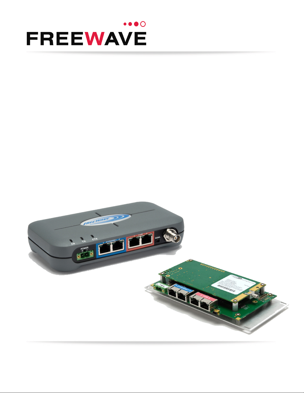
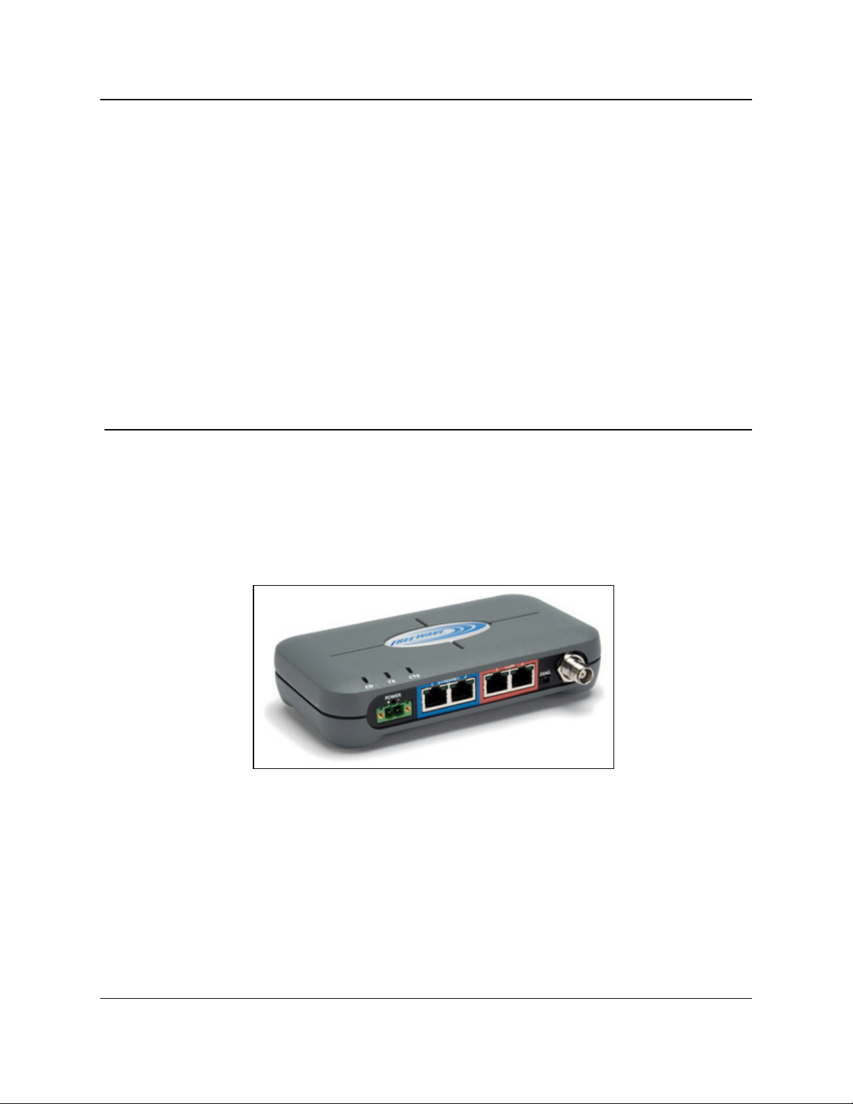
Thank you for purchasing the FreeWave Technologies, Inc. FGR2-P, -PE, & -PE-U device.
The FGR2-P, -PE, & -PE-U offer industrial serial and Ethernet wireless connectivity using the
license-free spread spectrum for data communication over long distances. The Radios are
compatible with other FreeWave FGR plus family Radios and have two Ethernet ports and two
serial ports, providing the ability to transition from serial to Ethernet data communications without
having to replace your wireless communications infrastructure.
Figure 1: FGR2-P, -PE, & -PE-U Product Image
LUM0024AB Rev May-2018 Page 14 of 211 Copyright © 2018FreeWave
This document is the property of FreeWave Technologies, Inc. and contains proprietary information owned by
FreeWave. This document cannot be reproduced in whole or in part by any means without written permission from
FreeWave Technologies, Inc.
Page 15
1. Introduction
FGR2-P, -PE, & -PE-U
User & Reference Manual
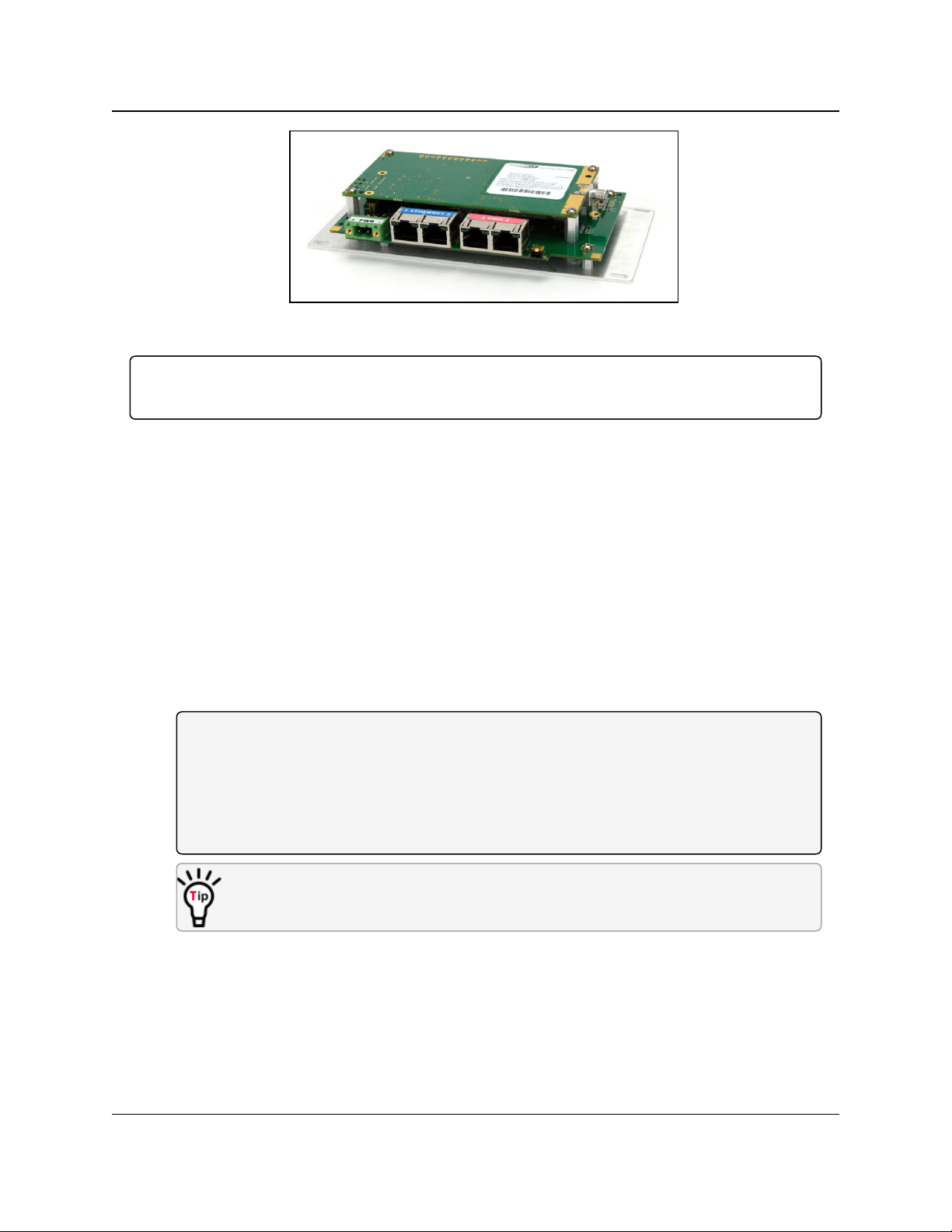
Figure 2: FGR2-P, -PE, & -PE-U Board
Important!: The FGR2-P, -PE, & -PE-U are compatible over the air with the FGRplusRE and the
MM2-P-T Radios. They are NOT compatible over the air with any other FreeWave products.
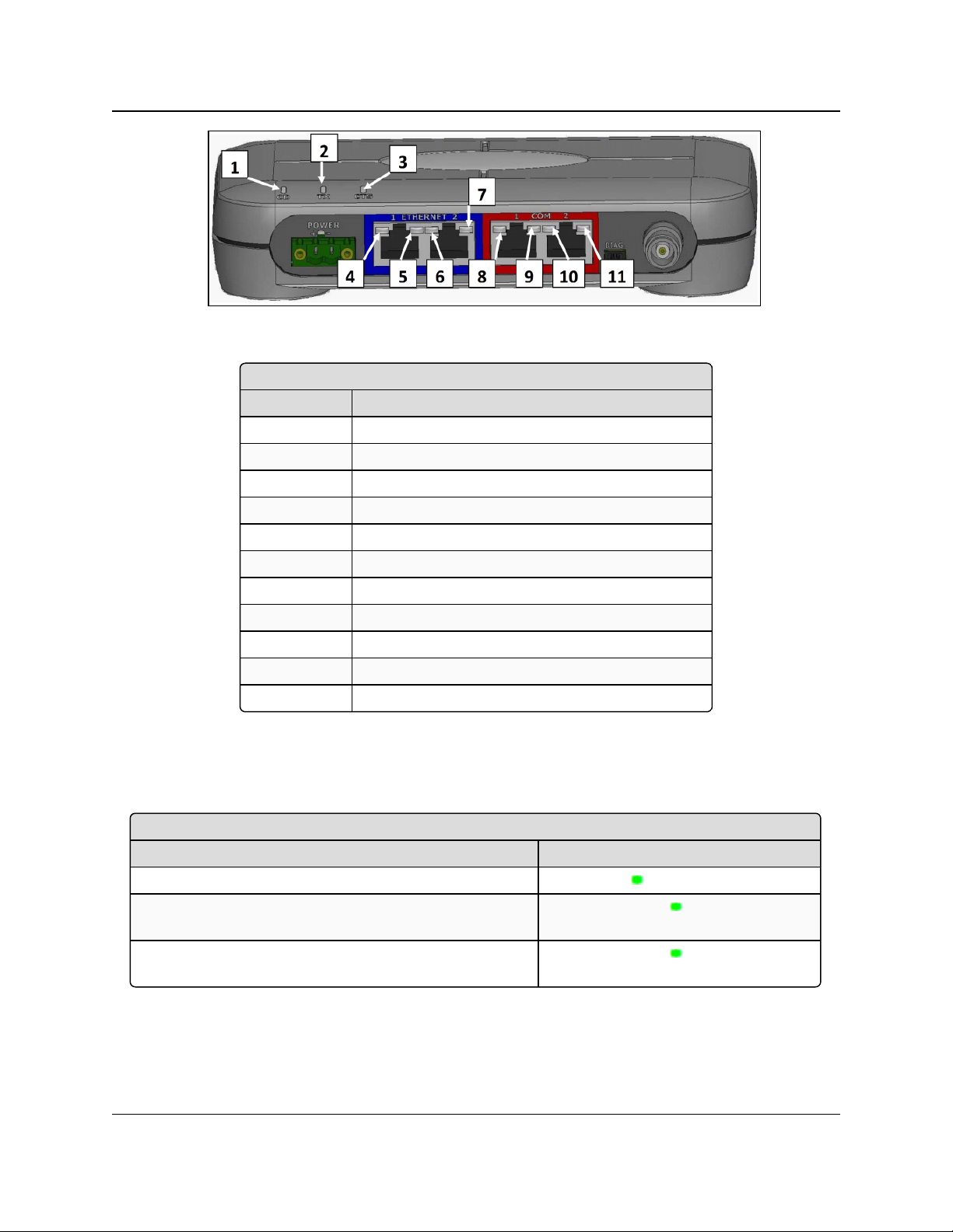
1.1. Components of the FGR2-P, -PE, & -PE-U PLUS Radios
The FGR2-P, -PE, & -PE-U PLUS Radios have these components:
l A power connector.
l LEDs to help determine when data is being received or sent from the radio and to provide
additional information about the radio's state.
l Two Ethernet ports (items 4 to 7, outlined in blue on the radio).
l Two COM ports (items 8 to 11, outlined in red on the radio).
l An antenna port.
l A diagnostic port (may be present on some units).
l The FGR2-P Radio has the same configuration as the FGR2-PE-U, without the enclosure.
Note: As of May-2018, the diagnostic port is active under certain configurations:
The diagnostic port does NOT function using MultiPoint Gateways and Point to Point
Repeaters.
The diagnostic port does function using MultiPoint Repeaters and Endpoints.
The diagnostic port functions with restrictions using Point to Point Gateways and Point to
Point Endpoints.
Radios running software v2.26 or later can be configured using a terminal emulator
connected to COM1.
LUM0024AB Rev May-2018 Page 15 of 211 Copyright © 2018FreeWave
This document is the property of FreeWave Technologies, Inc. and contains proprietary information owned by
FreeWave. This document cannot be reproduced in whole or in part by any means without written permission from
FreeWave Technologies, Inc.
Page 16
1. Introduction
Components of the FGR2-P, -PE, & -PE-U PLUS Radios
Label # Description
1 CD
2 TX
3 CTS
4 Ethernet 1 10 BaseT Link/Activity
5 Ethernet 1 100 BaseT Link
6 Ethernet 2 10 BaseT Link/Activity
7 Ethernet 2 100 BaseT Link
8 COM 1 Data (C1)
9 Error 1 (E1)
10 COM 2 Data (C2)
11 Error 2 (E2)
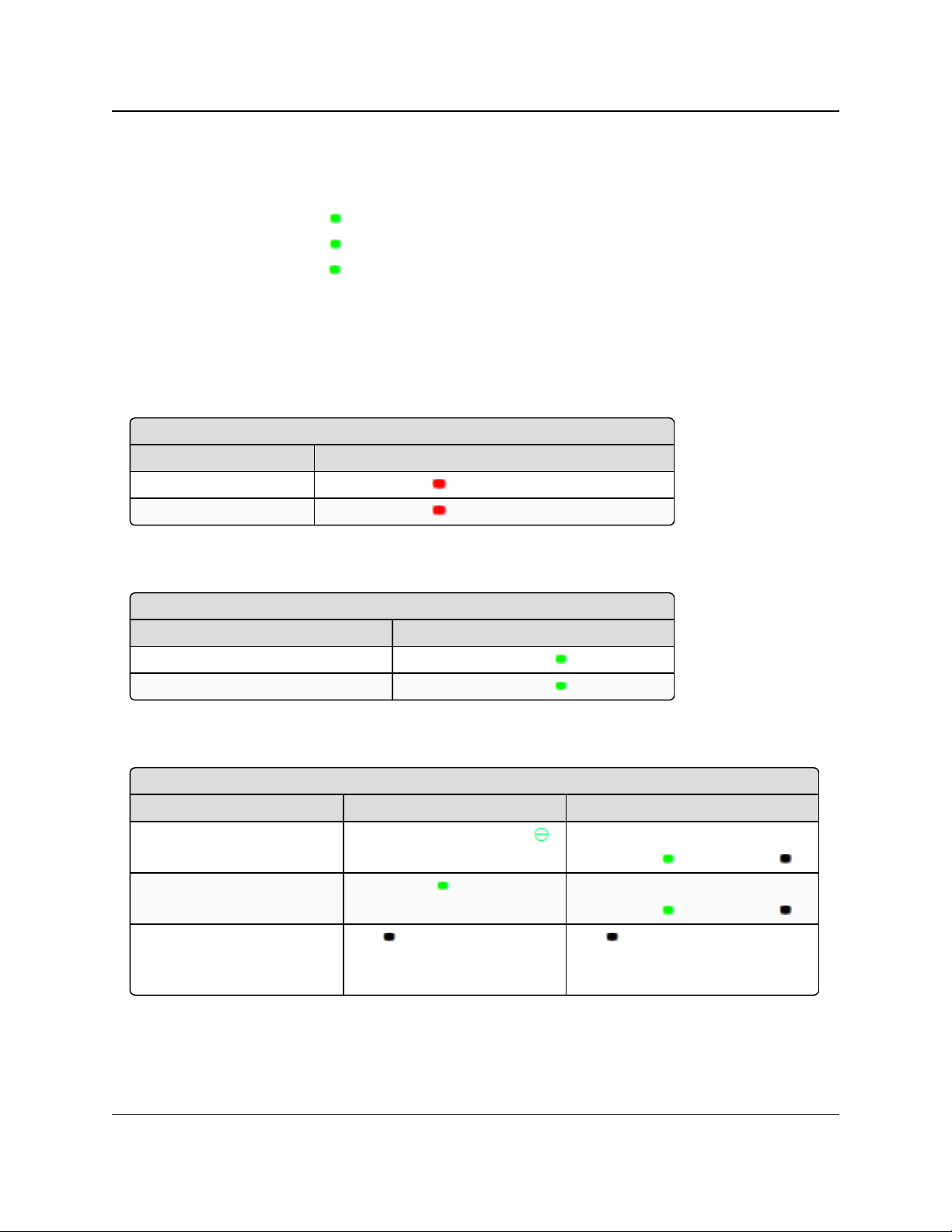
Authentication LEDs
Condition LED Pattern
Endpoint cannot contact RADIUS server Solid green E1 LED
Endpoint was denied authentication from the RADIUS
server
Alternating green E1 and E2 LED
Endpoint AES encryption key does not matchGateway
encryption key
Alternating green E1 and E2 LED
Figure 3: Components of the FGR2-P, -PE, & -PE-U PLUS Radios
FGR2-P, -PE, & -PE-U
User & Reference Manual
1.2. LED Designations
1.2.1. Authentication LEDs
LUM0024AB Rev May-2018 Page 16 of 211 Copyright © 2018FreeWave
This document is the property of FreeWave Technologies, Inc. and contains proprietary information owned by
FreeWave. This document cannot be reproduced in whole or in part by any means without written permission from
FreeWave Technologies, Inc.
Page 17
1. Introduction
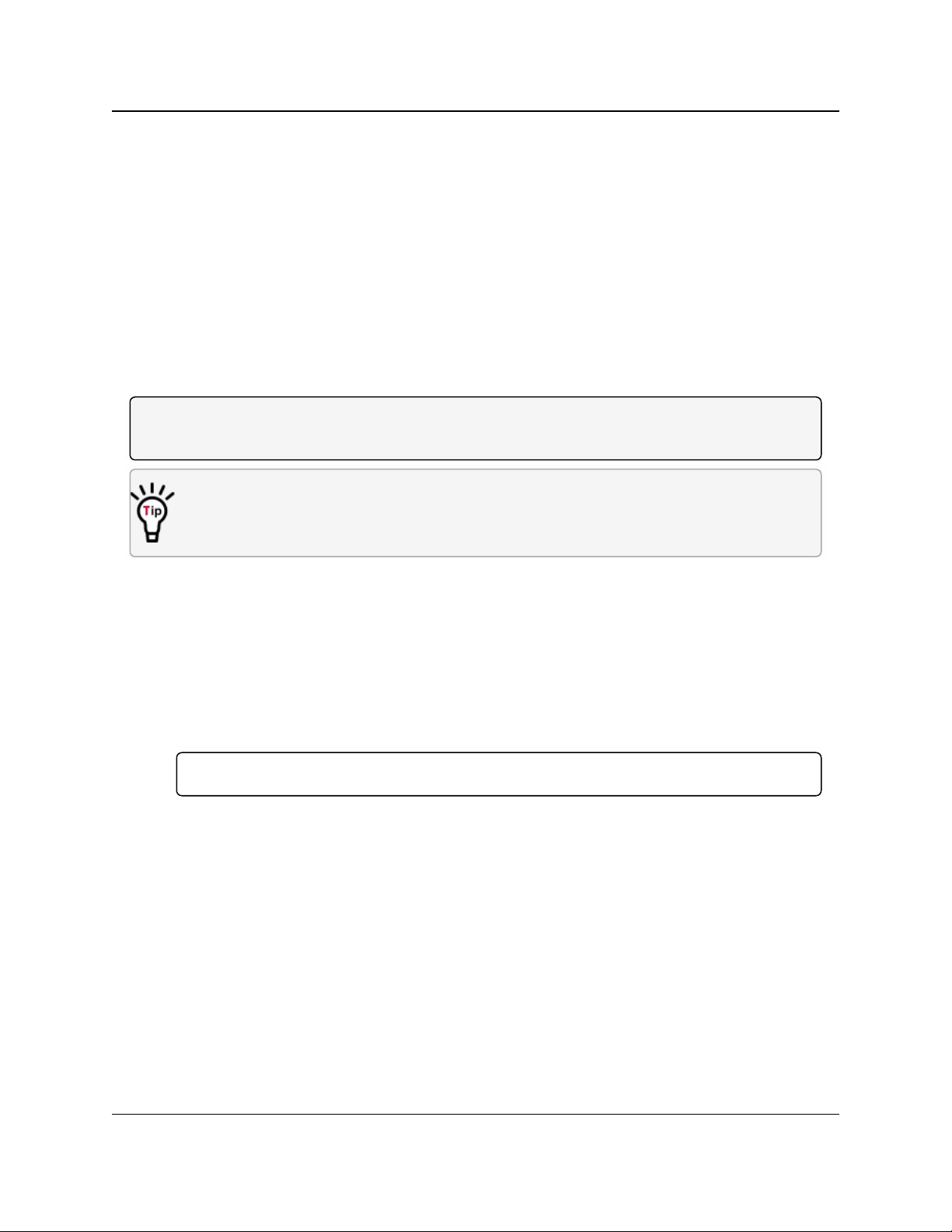
COM Port LED Conditions
Condition Communications Port 1 (C1) or 2 (C2)
Data streaming into RX Solid red bright
Data streaming out TX Solid red bright
Error LED Conditions
Condition Error Light (E1/E2)
Buffer overflow locally E1 LED is solid green
Buffer overflow in network E2 LED is solid green
Ethernet Port LED Conditions
Status 10 Base T Link / Activity 100 Base T Link LED
Linked, data activity
Blinking / Flickering green
Solid green
(100 BaseT /Off (10 BaseT )
Linked, no data activity Solid green Solid green
(100 BaseT /Off (10 BaseT )
Not linked.
Verify cable is in good
condition and plugged in.
Off Off
FGR2-P, -PE, & -PE-U
User & Reference Manual
1.2.2. Boot-Up LED Sequence
The LEDs on the FGR2-P, -PE, & -PE-U PLUS Radio follows this sequence when the radio
powers up:
1. C1 lights solid green .
2. C2 lights solid green , C1 remains lit.
3. E2 lights solid green , C1 and C2 remain lit.
4. C1 turns off.
5. C2 turns off.
6. E2 turns off.
1.2.3. COM Port LED Conditions
1.2.4. Error LED Conditions
1.2.5. Ethernet Port LED Conditions
LUM0024AB Rev May-2018 Page 17 of 211 Copyright © 2018FreeWave
This document is the property of FreeWave Technologies, Inc. and contains proprietary information owned by
FreeWave. This document cannot be reproduced in whole or in part by any means without written permission from
FreeWave Technologies, Inc.
Page 18
1. Introduction
FGR2-P, -PE, & -PE-U
User & Reference Manual
1.3. Choose a Radio Location
Placement of the FreeWave radio may have a significant impact on its performance. The key to
the overall robustness of the radio link is the height of the antenna.
When using an external antenna, placement of that antenna is critical to a solid data link. Other
antennas in close proximity are a potential source of interference.
Use the Radio Statistics on the Status window (on page 175) to help identify potential problems.
In general, FreeWave units with a higher antenna placement will have a better communication
link.
In practice, the radio should be placed away from computers, telephones, answering machines,
and other similar devices. The cable included with the radio provides ample distance for
placement away from other equipment.
Note: FreeWave offers directional and Omni-directional antennas with cable lengths ranging from 3
to 200 feet.
An adjustment as little as 2 feet in antenna placement may resolve noise issues.
In extreme cases, (e.g., Cellular Telephone tower interference) the band pass filters that
FreeWave offers may reduce this out-of-bandnoise.
1.4. Choose Point-to-Point (PTP) or Point-to-MultiPoint (PTMP) Operation
PTP Network
l A PTP network functions best when the network consists of one Gateway and one
Endpoint radio.
l A maximum of four Repeaters can be added to extend the reach of the network.
Important!: Adding a Repeater to a network cuts the network throughput by 50%.
In a Point-to-Point network, the Gateway determines all settings in an Endpoint or Repeater,
except for the Transmit Power and Retry Timeout. All other settings in a Point-to-Point network
are determined by the Gateway's settings.
PTMP Network
In a PTMP network, the Gateway radio is able to simultaneously communicate with numerous
Endpoint radios.
l In its simplest form, a PTMP network functions with the Gateway broadcasting its
messages to all Endpoint radios.
l If requested by the Gateway, the Endpoint radios respond to the Gateway when given data
by the device connected to the data port.
l This response depends on the setup.
LUM0024AB Rev May-2018 Page 18 of 211 Copyright © 2018FreeWave
This document is the property of FreeWave Technologies, Inc. and contains proprietary information owned by
FreeWave. This document cannot be reproduced in whole or in part by any means without written permission from
FreeWave Technologies, Inc.
Page 19

1. Introduction
l The network can be extended with as many Repeaters as is required.
FGR2-P, -PE, & -PE-U
User & Reference Manual
Important!: Adding a Repeater to a network cuts the network throughput by 50%.
1.4.1. Differences between PTP and PTMP Networks
PTP Network
In a PTP network all packets are acknowledged, whether sent from the Gateway to the Endpoint
or from the Endpoint to the Gateway.
PTMP Network
In a PTMP network, the user determines the number of times outbound packets from the
Gateway or Repeater to the Endpoint or other Repeaters are sent.
l The receiving radio, Endpoint or Repeater, accepts the first packet received that passes the
32 bit CRC.
l However, the packet is not acknowledged.
l On the return to the Gateway, all packets sent are acknowledged or retransmitted until they
are acknowledged.
l Therefore, the return link in a PTMP network is generally very robust.
Traditionally, a PTMP network is used in applications where data is collected from many
instruments and reported back to one central site. The architecture of such a network is different
from PTP applications. These parameters influence the number of radios that can exist in a PTMP
network:
l Baud Rate. The data rate between the radio and the device it is connected to could limit the
amount of data and the number of radios that can exist in a network.
l Contention: The amount of contention between Endpoint radios. Polled Endpoint radios
versus vs. timed Endpoint radios.
l Data Block Size. The longer the data blocks, the fewer number of deployed Endpoint
radios can exist in the network.
l Repeater Use. Using the Repeater setting in a PTP or PTMP network decreases the
overall network capacity by at least 50%.
Example: If the network polls once a day to retrieve sparse data, several hundred Endpoint
radios could be configured to a single Gateway.
However, if each Endpoint transmits larger amounts of data or data more frequently, fewer
Endpoint radios can link to the Gateway while receiving the same network performance.
When larger amounts of data are sent more frequently, the overall network bandwidth is
closer to capacity with fewer Endpoint radios.
LUM0024AB Rev May-2018 Page 19 of 211 Copyright © 2018FreeWave
This document is the property of FreeWave Technologies, Inc. and contains proprietary information owned by
FreeWave. This document cannot be reproduced in whole or in part by any means without written permission from
FreeWave Technologies, Inc.
Page 20
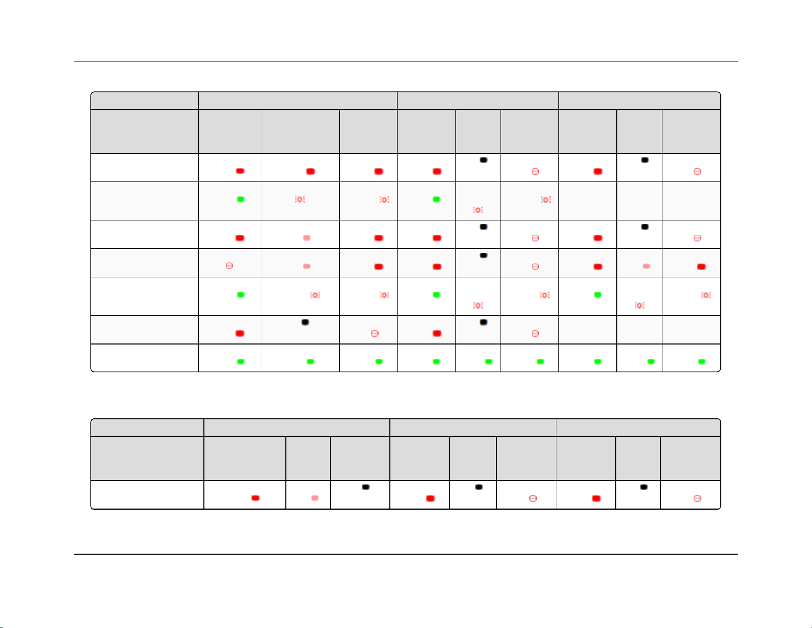
Gateway Endpoint Repeater
Condition
Carrier
Detect
(CD)
Transmit
(Tx)
Clear to
Send
(CTS)
Carrier
Detect
(CD)
Transmit
(Tx)
Clear to
Send
(CTS)
Carrier
Detect
(CD)
Transmit
(Tx)
Clear to
Send
(CTS)
Powered, no link Solid r ed
bright
Solid red
bright
Solid red
bright
Solid red
bright
Off
Blinking
red
Solid red
bright
Off
Blinking
red
Linked, no Repeater,
sending sparse data
Solid
green
Intermittent flash red Intermittent
flash red
Solid
green
Intermittent
flash red
Intermittent
flash red
n/a n/a n/a
Gateway calling Endpoint
through Repeater
Solid red
bright
Solid red
dim
Solid red
bright
Solid red
bright
Off
Blinking
red
Solid red
bright
Off
Blinking
red
Gateway linked to Repeater,
not to Endpoint
Flashing or ange Solid red
dim
Solid red
bright
Solid red
bright
Off
Blinking
red
Solid Red
bright
Solid red
dim
Solid red
bright
Repeater linked to Endpoint Solid
green
Intermittent
flash red
Intermittent
flash red
Solid
green
Intermittent
flash red
Intermittent
flash red
Solid
green
Intermittent
flash red
Intermittent
flash red
Mode 6 - waiting for ATD
command
Solid red
bright
Off
Blinking
red
Solid red
bright
Off
Blinking
red
n/a n/a n/a
Setup Mode Solid
green
Solid
green
Solid
green
Solid
green
Solid
green
Solid
green
Solid
green
Solid
green
Solid
green
Gateway Endpoint Repeater
Condition
Carrier
Detect
(CD)
Transmit
(Tx)
Clear to
Send
(CTS)
Carrier
Detect
(CD)
Transmit
(Tx)
Clear to
Send
(CTS)
Carrier
Detect
(CD)
Transmit
(Tx)
Clear to
Send
(CTS)
Powered, not linked Solid red
bright
Solid red
dim
Off
Solid red
bright
Off
Blinking
red
Solid red
bright
Off
Blinking
red
1. Introduction FGR2-P, -PE, & -PE-U User & Reference Manual
1.5. Point-to-Point (PTP) Operation LEDs
1.6. Point-to-MultiPoint (PTMP) Operation LEDs
LUM0024AB Rev May-2018 Page 20 of 211 Copyright © 2018FreeWave
This document is the property of FreeWave Technologies, Inc. and contains proprietary information owned by FreeWave. This document cannot be reproduced
in whole or in part by any means without written permission from FreeWave Technologies, Inc.
Page 21
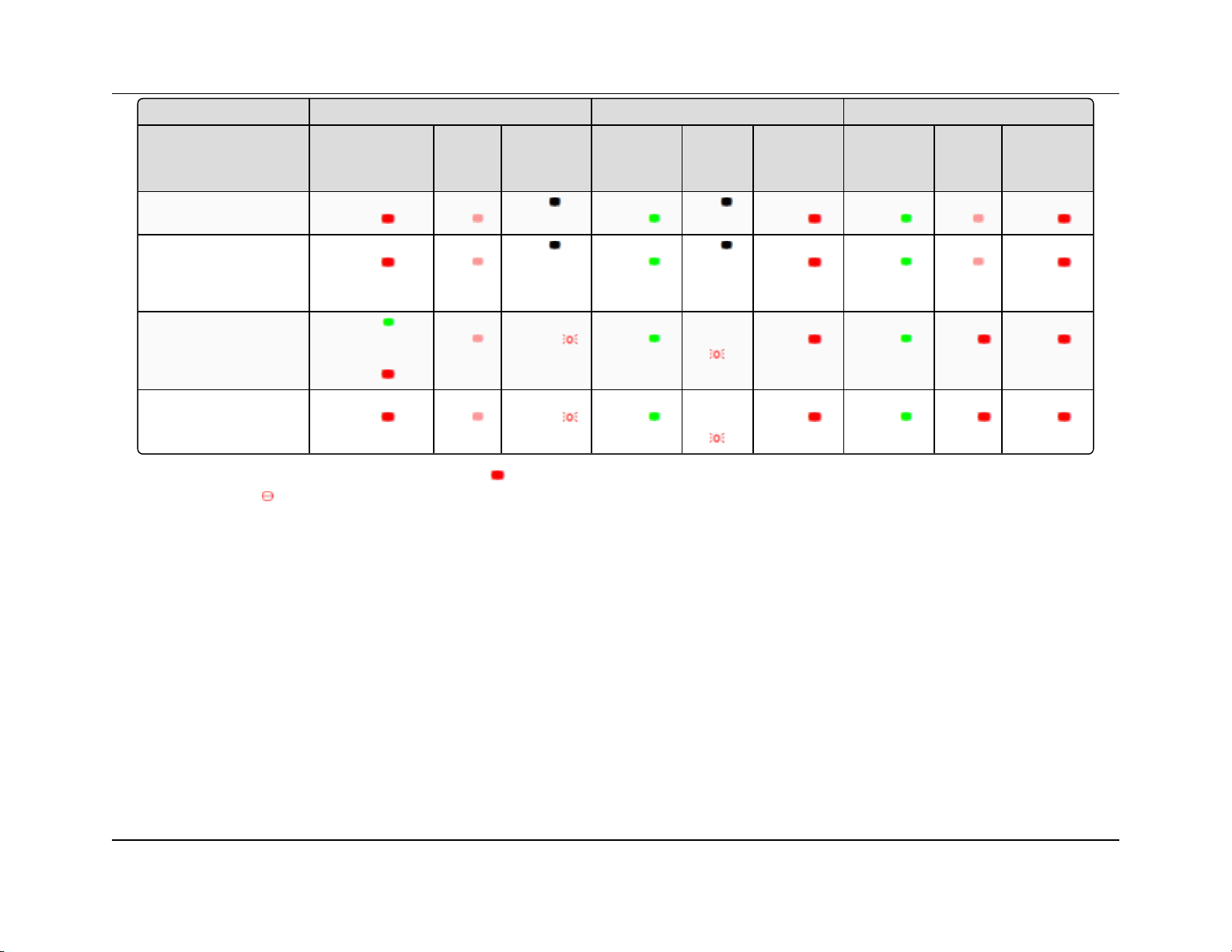
Gateway Endpoint Repeater
Condition
Carrier
Detect
(CD)
Transmit
(Tx)
Clear to
Send
(CTS)
Carrier
Detect
(CD)
Transmit
(Tx)
Clear to
Send
(CTS)
Carrier
Detect
(CD)
Transmit
(Tx)
Clear to
Send
(CTS)
Repeater and Endpoint linked
to Gateway, no data
Solid red
bright
Solid red
dim
Off
Solid
green
Off
Solid red
bright
Solid
green
Solid red
dim
Solid red
bright
Repeater and Endpoint linked
to Gateway,
Gateway sending data to
Endpoint
Solid red
bright
Solid red
dim
Off
Solid
green
Off
Solid red
bright
Solid
green
Solid red
dim
Solid red
bright
Repeater and Endpoint linked
to Gateway,
Endpoint sending data to
Gateway
Solid green RCV
data
or Solid red
bright
Solid red
dim
Intermittent
flash red
Solid
green
Intermittent
flash red
Solid red
bright
Solid
green
Solid red
bright
Solid red
bright
Gateway with diagnostics
program running
Solid red
bright
Solid red
dim
Intermittent
flash red
Solid
green
Intermittent
flash red
Solid red
bright
Solid
green
Solid red
bright
Solid red
bright
1. Introduction FGR2-P, -PE, & -PE-U User & Reference Manual
* in an idle condition, the CTS LED is solid red with a solid link, as the link weakens the CTS LED on the Repeater and Endpoint
begins to blink
LUM0024AB Rev May-2018 Page 21 of 211 Copyright © 2018FreeWave
This document is the property of FreeWave Technologies, Inc. and contains proprietary information owned by FreeWave. This document cannot be reproduced
in whole or in part by any means without written permission from FreeWave Technologies, Inc.
Page 22

FGR2-P, -PE, & -PE-U
User & Reference Manual
2. Set Up and Program Radios
This section provides details about setup, programming, and defining who has access to the
FGR2-P, -PE, & -PE-U PLUS Radios using the available setup tools. This information is included:
l Basic Steps to Programming the FGR2-P, -PE, & -PE-U PLUS Radios (on page 23)
l Powering the FGR2-P, -PE, & -PE-U PLUS Radio (on page 24)
l Identify and Change the FGR2-P, -PE, & -PE-U PLUS Radio's IP Address (on page 24)
l Configuration Tool Options (on page 25)
l Accessing the Configuration Windows (on page 27)
l Navigating the Configuration Windows (on page 29)
l Providing Site Information (on page 32)
l Use the MultiPoint Gateway to Change All Connected Radios (on page 33)
l Creating User Logins (on page 36)
l Upgrading the FGR2-P, -PE, & -PE-U PLUS Radio Software Using a TFTP Server (on
page 41)
l Resetting Radios to the Factory Default Settings (on page 49)
LUM0024AB Rev May-2018 Page 22 of 211 Copyright © 2018FreeWave
This document is the property of FreeWave Technologies, Inc. and contains proprietary information owned by
FreeWave. This document cannot be reproduced in whole or in part by any means without written permission from
FreeWave Technologies, Inc.
Page 23
2. Set Up and Program Radios
FGR2-P, -PE, & -PE-U
User & Reference Manual
2.1. Basic Steps to Programming the FGR2-P, -PE, & -PE-U PLUS Radios
This basic procedure programs any FreeWave PLUS Radio.
1. Determine or set the radio's IP address.
Note: The PLUS radio can be programmed using the terminal menu available through the
radio's serial port without having to know the radio's IP address.
2. Be familiar with the network and know if it is a Point-to-Point (PTP) or Point-to-MultiPoint
(PTMP) configuration.
Note: Most FreeWave networks are PTMP.
3. Open the radio's Configuration Windows.
4. Set the radio's operation mode (e.g., Gateway, Repeater, or Endpoint).
5. Set the radio's network type (PTP or PTMP).
6. Program the radio, verifying all devices in a PTMP network have the same settings for
these parameters:
l Frequency Key
l Max Packet Size
l Min Packet Size
l Network ID
l RF Data Rate
7. Setup the Call Book if the radio is in a network NOT using Network IDs.
See the Call Book window (on page 158).
FREEWAVE Recommends: While the Call Book is an option in Point-to-MultiPoint networks,
FreeWave strongly recommends using the Network ID feature in most applications.
If a large MultiPoint network is implemented using the Call Book and a radio needs to be added or
replaced in the network, each radio MUST be physically reprogrammed in the network and the new
serial number entered in the radio's Call Book.
This can be a time consuming process and can cause a delay in getting the network back up and
running.
Note: If using a Network ID, see the Network ID and Subnet ID parameters described in the Radio
Settings (on page 82).
LUM0024AB Rev May-2018 Page 23 of 211 Copyright © 2018FreeWave
This document is the property of FreeWave Technologies, Inc. and contains proprietary information owned by
FreeWave. This document cannot be reproduced in whole or in part by any means without written permission from
FreeWave Technologies, Inc.
Page 24
2. Set Up and Program Radios
FGR2-P, -PE, & -PE-U
User & Reference Manual
2.1.1. PTMP Network Considerations
Planning is important when installing PTMP networks. A PTMP network requires that several
parameters are set consistently on ALL radios in the network. This includes:
l Frequency Key.
l Min and Max Packet Size.
l Network ID.
l RF Data Rate.
Important!: If several independent, PTMP networks are located in close proximity, it is very
important to include as much frequency and time diversity as possible using different Frequency
Key and Min and Max Packet Sizes.
2.2. Powering the FGR2-P, -PE, & -PE-U PLUS Radio
Connect the FGR2-P, -PE, & -PE-U PLUS Radio to a positive DC power supply with +6.0 to
+30.0 VDC (typically, +12 VDC).
The power supply used MUST provide more current than the amount of current drain listed on the
FGR2-P, -PE, & -PE-U Technical Specifications (on page 196) for the voltage used.
Example: When using +12 VDC, the power supply must provide current capability greater than the
drain that is required for transmit or greater than 550 mA.
Note: For any application where the radio is used in a UL-controlled environment, the power supply
MUST be a Class 2 power source. Using a dedicated power supply line is preferred.
Warning! If the power supply is above approximately +18 to +20 VDC, use a 1 ohm resistor in
line with B+ input to the radio.
Warning! If the power supply line runs outside the enclosure, use electrostatic discharge
(ESD) protectors to protect the radio from electric shock and transient voltage suppressors
(TVS) to protect from an over-voltage situation.
Using both helps to ensure long-term, reliable operation.
2.3. Identify and Change the FGR2-P, -PE, & -PE-U PLUS Radio's IP Address
Note: In software versions 2.26 and later, the FGR2-P, -PE, & -PE-U PLUS radio can be
programmed through the radio's COM1 port without having to know the radio's IP address.
LUM0024AB Rev May-2018 Page 24 of 211 Copyright © 2018FreeWave
This document is the property of FreeWave Technologies, Inc. and contains proprietary information owned by
FreeWave. This document cannot be reproduced in whole or in part by any means without written permission from
FreeWave Technologies, Inc.
Page 25
2. Set Up and Program Radios
Window Used To
Status window View all device status information.
Note: See Viewing Radio Status and Statistics on page 129.
IP Setup window Use to identify and configure the IP address, Subnet Mask, and Default
Gateway.
Important!: Consult with the Network Administrator before changing
these settings.
Note: See IP and Network Communication Settings on page 51.
FGR2-P, -PE, & -PE-U
User & Reference Manual
It is good practice to identify the IP addresses of all the devices in the network and verify each
is unique.
l The FGR2-P, -PE, & -PE-U PLUS Radio's default IP address is 192.168.111.100.
l The default user name is admin.
l The default password is admin.
Caution: Each radio in the network MUST have its own unique IP address.
Putting multiple devices with the same IP address on the same network can cause network
problems.
2.4. Configuration Tool Options
After the Ethernet address is identified and changed on the FGR2-P, -PE, & -PE-U PLUS radio,
use the Configuration Windows setup tools to configure the radio.
A Web browser must be installed on the computer to access the Configuration Windows.
Note: See Accessing the Configuration Windows on page 27.
Example: To setup a serial port, access all the parameters for the first serial port in the Serial Setup
1 window.
LUM0024AB Rev May-2018 Page 25 of 211 Copyright © 2018FreeWave
This document is the property of FreeWave Technologies, Inc. and contains proprietary information owned by
FreeWave. This document cannot be reproduced in whole or in part by any means without written permission from
FreeWave Technologies, Inc.
Page 26

2. Set Up and Program Radios
Window Used To
Serial Setup window
(Serial Setup 2)
Use to identify and configure the port numbers and data settings for each
serial port.
Important!: These settings MUST match the device to which each
port is connected.
Note: See Serial Port Settings on page 64.
Radio Setup window Use to identify and configure the radio’s:
l Operation Mode.
l Transmission Characteristics.
l MultiPoint Parameters.
l Call Book.
Note: See Radio Settings on page 82.
Security window Use to identify and configure the:
l RADIUS server authentication.
l MAC filtering.
l AES Encryption information.
Note: See Security Settings on page 102.
SNMP window Use to identify and configure the SNMP management features of the radio.
l The radio supports SNMP versions 1, 2, and 3.
l All of the SNMP-manageable objects for FreeWave's radios are
contained in a single MIB file.
l See Object List for FREEWAVE-TECHNOLOGIES-MIB on page
201.
Note: This file is available from FreeWave upon request.
See SNMP Settings on page 117.
Diagnostics window Use to view this information:
l Signal level
l Noise level
l Signal-to-noise delta
l Receive rate for each frequency available to the radio.
Note: See Viewing Radio Status and Statistics on page 129.
FGR2-P, -PE, & -PE-U
User & Reference Manual
LUM0024AB Rev May-2018 Page 26 of 211 Copyright © 2018FreeWave
This document is the property of FreeWave Technologies, Inc. and contains proprietary information owned by
FreeWave. This document cannot be reproduced in whole or in part by any means without written permission from
FreeWave Technologies, Inc.
Page 27
2. Set Up and Program Radios
Window Used To
Users window Use to add or change logins for the radio.
l A maximum of nine (9) custom users can be created for each radio.
l The admin user is the permanent 10th user.
Note: See Creating User Logins on page 36.
Tools window Use to edit the site information and upgrade the radio’s Software.
Note: In a MultiPoint Gateway, use to enable the Global Change
functionality.
FGR2-P, -PE, & -PE-U
User & Reference Manual
2.5. Accessing the Configuration Windows
Each FGR2-P, -PE, & -PE-U PLUS Radio includes Configuration Windows to identify, change,
and program its settings.
Note: See Configuration Windows for detailed information.
l A Web browser must be installed on the computer to access the Configuration Windows.
l The router / switch and/or the computer accessing the radio must be on the same subnet.
If the Subnet Mask for the network is 255.255.255.0, the first three octets, or sections, of the IP
address on the radio and the IP address on the computer MUST match. The last octet is unique.
Example: If the subnet mask is 255.255.255.0 and the radio's IP address is 198.168.111.100, then
the computer must have an IP address that begins with 198.168.111.
The last section of the IP address is unique to identify the device.
Administrator Login and Password
l The default User Name for the administrator login is admin.
l The default Password is admin.
Note: The administrator login has full permission to change all settings on the radio, including
upgrading software.
Guest Login and Password
l The default User Name for the guest login is guest.
l The default Password is guest.
l The guest login can view the settings but CANNOT:
l save any changes.
l view the Security window (on page 163).
LUM0024AB Rev May-2018 Page 27 of 211 Copyright © 2018FreeWave
This document is the property of FreeWave Technologies, Inc. and contains proprietary information owned by
FreeWave. This document cannot be reproduced in whole or in part by any means without written permission from
FreeWave Technologies, Inc.
Page 28
2. Set Up and Program Radios
l view the Tools window (on page 178).
l reboot the radio.
Note: The button is not available to Guest users.
FGR2-P, -PE, & -PE-U
User & Reference Manual
Procedure
1. Connect the FGR2-P, -PE, & -PE-U radio’s Ethernet port to either a computer or a router /
switch.
2. Apply power to the radio.
3. Open a web browser.
4. Enter the IP address of the radio into the address bar.
Note: The default IP address is 192.168.111.100.
Example: Enter 192.168.111.100 in the address bar of the web browser to access a radio
with that IP address.
5. Refresh the browser window.
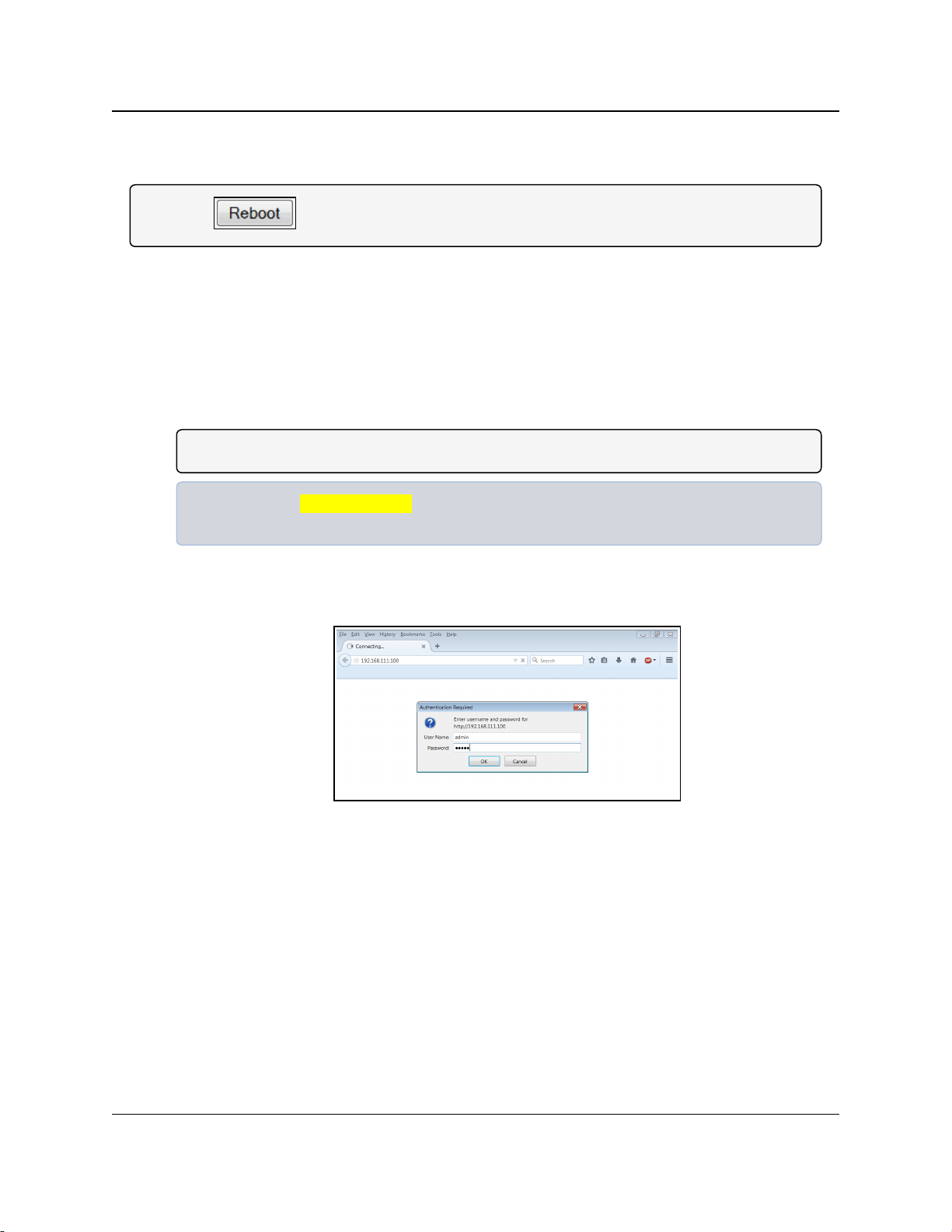
The Authentication Required dialog box opens.
6. Enter the User Name and Password to access the radio.
Figure 4: Authentication Required dialog box
7. Click OK.
The Status window opens.
LUM0024AB Rev May-2018 Page 28 of 211 Copyright © 2018FreeWave
This document is the property of FreeWave Technologies, Inc. and contains proprietary information owned by
FreeWave. This document cannot be reproduced in whole or in part by any means without written permission from
FreeWave Technologies, Inc.
Page 29
2. Set Up and Program Radios
FGR2-P, -PE, & -PE-U
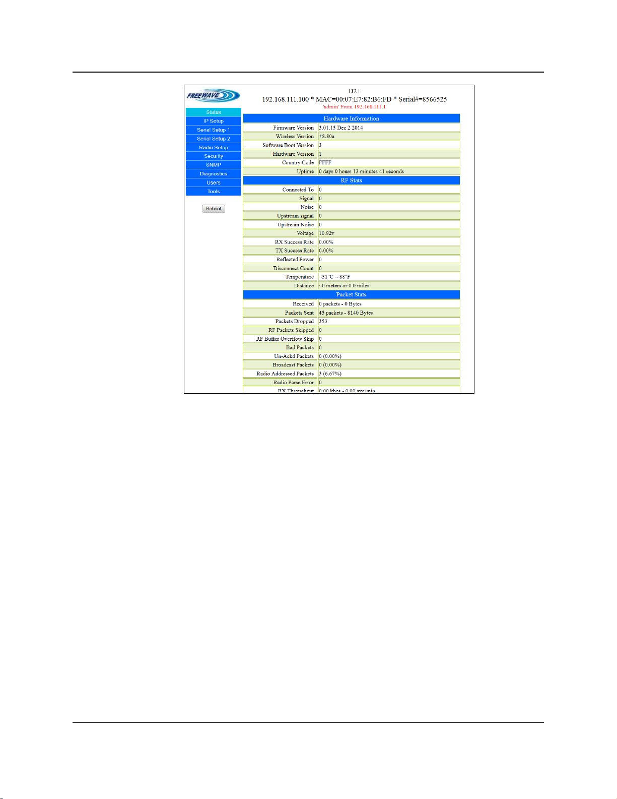
User & Reference Manual
Figure 5: FGR2-P, -PE, & -PE-U Status window
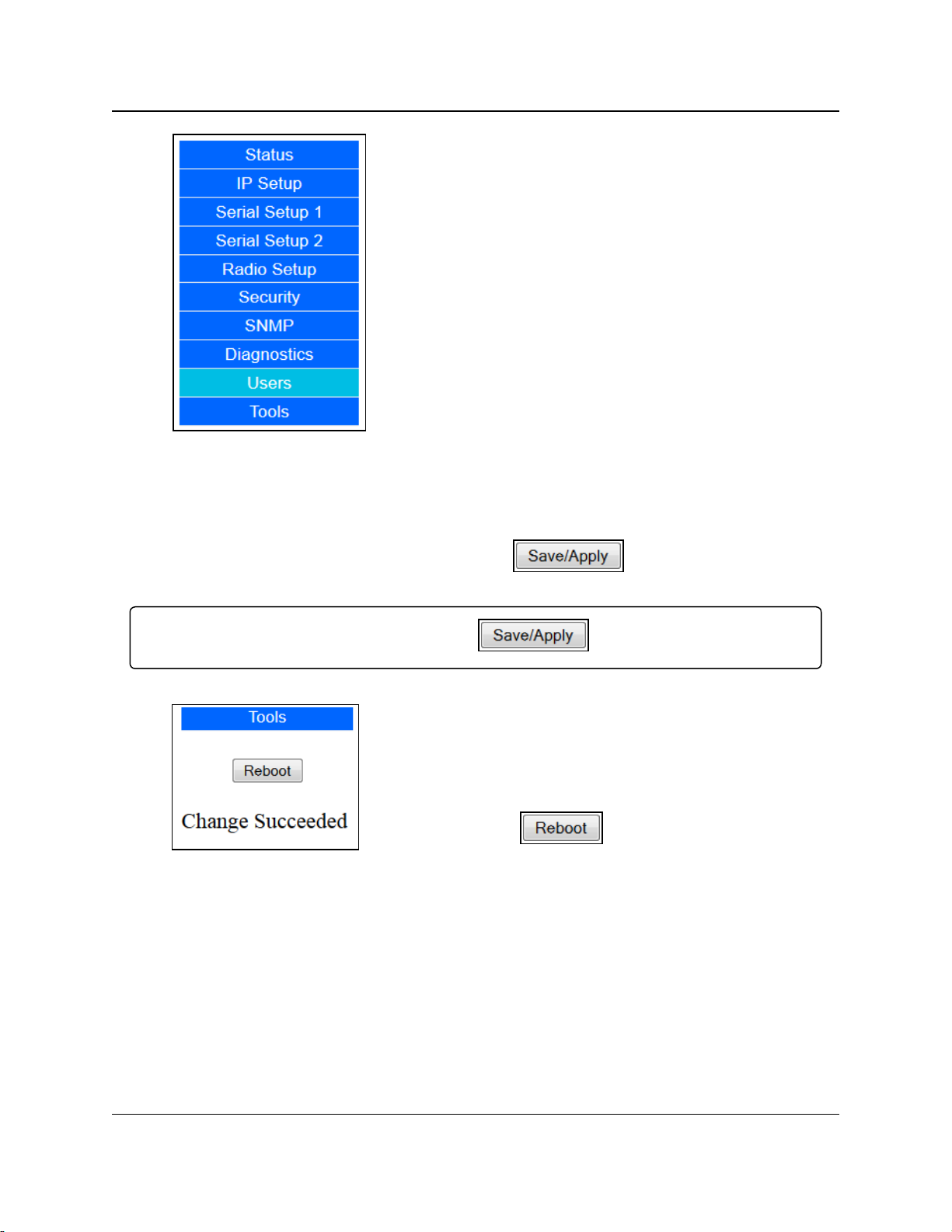
2.6. Navigating the Configuration Windows
2.6.1. Menu bar
The Configuration Windows group the parameters into the Menu bar on the left side of all
windows.
LUM0024AB Rev May-2018 Page 29 of 211 Copyright © 2018FreeWave
This document is the property of FreeWave Technologies, Inc. and contains proprietary information owned by
FreeWave. This document cannot be reproduced in whole or in part by any means without written permission from
FreeWave Technologies, Inc.
Page 30
2. Set Up and Program Radios
Figure 6: Menu bar
2.6.2. Save and Apply
FGR2-P, -PE, & -PE-U
User & Reference Manual
l Click any item in the Menu bar to open that
Configuration window.
l The currently selected window is highlighted in the
Menu bar.
When making changes to the radio settings, click the button before navigating
away from a window or rebooting the radio to save the changes.
Important!: No changes take effect until you click .
l When the changes have been successfully saved and
applied, the Change Succeeded message appears
under the button.
Figure 7: Change
Succeeded message
LUM0024AB Rev May-2018 Page 30 of 211 Copyright © 2018FreeWave
This document is the property of FreeWave Technologies, Inc. and contains proprietary information owned by
FreeWave. This document cannot be reproduced in whole or in part by any means without written permission from
FreeWave Technologies, Inc.
Page 31

2. Set Up and Program Radios
Figure 8: Changed Baud
Rate before
is clicked.
2.6.3. Reboot
FGR2-P, -PE, & -PE-U
User & Reference Manual
l Any change made in the Configuration Windows that
is not yet saved is highlighted in yellow.
l This highlight indicates that you need to click
before navigating away from the
page, or the changes will be lost.
l Some setting changes (e.g., changes to the IP
Setup) require a reboot to complete the changes.
l When such a change is made, the Change
Succeeded message below the button
changes to include a link labeled Reboot Required.
Note: The button is not available to
Guest users.
Figure 9: Reboot
Required message
l
Below the Menu bar is the button.
Click this button to force the radio to reboot.
l Click either the Reboot Required link or the
button to reboot the radio and apply the
requested changes.
Important!: The requested changes are NOT
made until the radio is rebooted.
Note: A Reboot Required link appears at the
top of every page until the radio is rebooted.
LUM0024AB Rev May-2018 Page 31 of 211 Copyright © 2018FreeWave
This document is the property of FreeWave Technologies, Inc. and contains proprietary information owned by
FreeWave. This document cannot be reproduced in whole or in part by any means without written permission from
FreeWave Technologies, Inc.
Page 32

2. Set Up and Program Radios
FGR2-P, -PE, & -PE-U
User & Reference Manual
2.7. Providing Site Information
For each radio in the network, information to help identify that FGR2-P, -PE, & -PE-U PLUS radio
(i.e., name and contact information) can be provided. The site information appears on the Status
window on page 175.
Procedure
1. Follow the procedure for Accessing the Configuration Windows (on page 27).
The Status window opens.
2. On the Menu bar, click Tools.
The Tools window opens.
Figure 10: FGR2-P, -PE, & -PE-U Tools window
Important!: On the FGR2-P, -PE, & -PE-U radios, the Modem Mode list box on the Radio
Setup window on page 156 must be set to Gateway for the
button to be visible.
3. In the Change Site Information area:
Important!: Free form text fields CANNOT use any of these characters: %&+=<>
a. In the Site Name text box, enter a maximum of 25 characters to help identify the
radio.
b. In the Site Contact text box, enter a maximum of 25 characters about who to contact
about the site's status.
c. In the System Name text box, enter a maximum of 32 characters to identify the
system the radio operates in.
d. In the Notes text box, enter a maximum of 50 characters to describe the radio or the
LUM0024AB Rev May-2018 Page 32 of 211 Copyright © 2018FreeWave
This document is the property of FreeWave Technologies, Inc. and contains proprietary information owned by
FreeWave. This document cannot be reproduced in whole or in part by any means without written permission from
FreeWave Technologies, Inc.
Page 33

2. Set Up and Program Radios
FGR2-P, -PE, & -PE-U
User & Reference Manual
site.
4.
Click to save the changes.
2.8. Use the MultiPoint Gateway to Change All Connected Radios
Important!: The Global Change function can ONLY be enabled or disabled using the Configuration
Windows.
Often, the settings on radios in the network should be the same as the settings in the MultiPoint
Gateway. Instead of changing each radio individually, use the Global Change function to push
the IP Setup, Radio Setup, Security, SNMP, and User settings to all connected radios in the
network.
Important!: The Global Change can only be successfully performed if the Endpoint or Repeater
radio is linked wirelessly to the Gateway.
1. Follow the procedure for Accessing the Configuration Windows (on page 27).
The Status window opens.
2. On the Menu bar, click Tools.
The Tools window opens.
Figure 11: FGR2-P, -PE, & -PE-U Tools window
Important!: On the FGR2-P, -PE, & -PE-U radios, the Modem Mode list box on the Radio
Setup window on page 156 must be set to Gateway for the
button to be visible.
LUM0024AB Rev May-2018 Page 33 of 211 Copyright © 2018FreeWave
This document is the property of FreeWave Technologies, Inc. and contains proprietary information owned by
FreeWave. This document cannot be reproduced in whole or in part by any means without written permission from
FreeWave Technologies, Inc.
Page 34

2. Set Up and Program Radios
Global Functionality Changes
Window Description
IP Setup window l The IP Address text box is hidden.
l It cannot be part of a global change.
Radio Setup window l The Network Type and Modem Mode list boxes are hidden.
l They do NOT change as part of a global change.
Important!: Changes made to the settings on the Radio Setup
window can cause the radios to lose communication with the
Gateway and/or MultiPoint Repeaters.
Use caution when making global changes.
3.
Click .
The button changes to .
Note: Click that button to turn off global changing.
When enabled, the All Changes to All Radios message appears.
Figure 12: All Changes to All Radios message
l On the Gateway, the Push Globally button replaces the Save/Apply button on the
windows that allow global changes.
l Click Push Globally to send any changes made to the parameters on that window
are sent to all the connected radios.
l Every connected radio that receives the changes reboots after the changes are
applied.
l The Configuration Windows on the remote radios are not accessible until the reboot
completes.
FGR2-P, -PE, & -PE-U
User & Reference Manual
Note: The settings on the MultiPoint Gateway are NOT changed during a global change.
When the Global Change functionality is enabled, these changes occur in these windows:
LUM0024AB Rev May-2018 Page 34 of 211 Copyright © 2018FreeWave
This document is the property of FreeWave Technologies, Inc. and contains proprietary information owned by
FreeWave. This document cannot be reproduced in whole or in part by any means without written permission from
FreeWave Technologies, Inc.
Page 35

2. Set Up and Program Radios
Global Functionality Changes
Window Description
Security window l All settings on the Security window can be part of a global change.
Caution: When changing the AES Encryption Key
globally, make the first change on the MultiPoint Gateway.
After the Gateway has been changed, push the new key to
the other radios in the network.
If this is not done in this order, changing the encryption key
can cause radios to lose connectivity with the Gateway for
an extended period of time.
SNMP window l All settings on the SNMP window can be part of a global change.
Users window l The Edit Group Level Rights area and the User Accounts Level
can be adjusted using global changes.
Important!: User accounts and User passwords CANNOT be
created or deleted using global changes.
FGR2-P, -PE, & -PE-U
User & Reference Manual
LUM0024AB Rev May-2018 Page 35 of 211 Copyright © 2018FreeWave
This document is the property of FreeWave Technologies, Inc. and contains proprietary information owned by
FreeWave. This document cannot be reproduced in whole or in part by any means without written permission from
FreeWave Technologies, Inc.
Page 36

2. Set Up and Program Radios
FGR2-P, -PE, & -PE-U
User & Reference Manual
2.9. Creating User Logins
To limit who can access the FGR2-P, -PE, & -PE-U PLUS Radios in the network and edit
configuration settings, a maximum of nine (9) custom users with login access can be created.
Note: The permanent admin login is the 10th login.
Procedure
1. Defining User Groups on page 36.
2. Editing User Group Rights on page 37.
3. Add and Delete Users on page 38.
4. Changing User Passwords on page 40.
2.9.1. Defining User Groups
User groups set the access rights for the Configuration Windows for a radio. Users are assigned
to one of three Groups and inherit the access rights that are set for that Group.
There are three pre-defined Groups (Groups 1, 2, and 3).
Note: Additional Groups cannot be added.
In each group, assign one access level to each page or tab:
l No Access - Users cannot see the settings in the tab or page.
l Any attempt to navigate to the tab or page shows an Access Denied message.
l Read Only - Users can see the settings in the tab or page, but cannot save or apply any
changes.
l Full Access - Users are able to see the settings in the tab or page and can save and apply
changes.
When a user is created it is assigned to a group. The group number corresponds to the user group
and the user inherits the permissions assigned to that group.
Example: If Group 1 has Read Only access to the IP Setup parameters and No Access to the
Security parameters, any user assigned to Group 1 can view IP Setup parameters but not make
changes, and receives an Access Denied message if they try to access the Security window on
page 163.
Note: The group assigned to the admin user cannot be changed.
The admin user always has Full Access to all pages.
LUM0024AB Rev May-2018 Page 36 of 211 Copyright © 2018FreeWave
This document is the property of FreeWave Technologies, Inc. and contains proprietary information owned by
FreeWave. This document cannot be reproduced in whole or in part by any means without written permission from
FreeWave Technologies, Inc.
Page 37

2. Set Up and Program Radios
User & Reference Manual
2.9.2. Editing User Group Rights
1. Follow the procedure for Accessing the Configuration Windows (on page 27).
The Status window opens.
2. On the Menu bar, click Users.
The Users window opens.
FGR2-P, -PE, & -PE-U
Figure 13: FGR2-P, -PE, & -PE-U Users window
3. In the Edit Group Level Rights area, click the list box arrow for each group and select the
access rights for each window.
4.
Click to save the changes and apply them to the radio.
LUM0024AB Rev May-2018 Page 37 of 211 Copyright © 2018FreeWave
This document is the property of FreeWave Technologies, Inc. and contains proprietary information owned by
FreeWave. This document cannot be reproduced in whole or in part by any means without written permission from
FreeWave Technologies, Inc.
Page 38

2. Set Up and Program Radios
FGR2-P, -PE, & -PE-U
User & Reference Manual
2.9.3. Add and Delete Users
A maximum of nine (9) custom users with login access can be created to limit who can access the
FGR2-P, -PE, & -PE-U PLUS Radios in the network and edit configuration settings.
Important!: Users can only be created and edited using the Configuration Windows.
Note: The permanent admin login is the 10th login.
Adding a User
1. Follow the procedure for Accessing the Configuration Windows (on page 27).
The Status window opens.
2. On the Menu bar, click Users.
The Users window opens.
Figure 14: FGR2-P, -PE, & -PE-U Users window
3.
In the User Accounts area, click the Add User link or click the green plus button.
The Add User window opens.
LUM0024AB Rev May-2018 Page 38 of 211 Copyright © 2018FreeWave
This document is the property of FreeWave Technologies, Inc. and contains proprietary information owned by
FreeWave. This document cannot be reproduced in whole or in part by any means without written permission from
FreeWave Technologies, Inc.
Page 39

2. Set Up and Program Radios
Figure 15: Add User window
4. In the User Name text box, enter a name that identifies the user.
Example: Enter guest or a user's first initial and last name.
FGR2-P, -PE, & -PE-U
User & Reference Manual
5. Click the User Level list box arrow and select 1, 2, or 3 to assign the user to a group.
Note: See Defining User Groups (on page 36) for more information.
6. In the Password and Confirm Password text boxes, enter the user password to enter
when accessing restricted windows.
7. Click Add User to close the Add User window and immediately create the new user.
Deleting a User
1. Follow the procedure for Accessing the Configuration Windows (on page 27).
The Status window opens.
2. On the Menu bar, click Users.
The Users window opens.
3.
In the User Accounts area, click the red button next to the user to delete.
Caution: There is no confirmation message to delete the User.
The selected User is deleted immediately.
LUM0024AB Rev May-2018 Page 39 of 211 Copyright © 2018FreeWave
This document is the property of FreeWave Technologies, Inc. and contains proprietary information owned by
FreeWave. This document cannot be reproduced in whole or in part by any means without written permission from
FreeWave Technologies, Inc.
Page 40

2. Set Up and Program Radios
FGR2-P, -PE, & -PE-U
User & Reference Manual
2.9.4. Changing User Passwords
Important!: User Passwords can ONLY be changed in the Configuration Windows.
When a user is created, they are assigned a password. This password can be changed at any
time.
1. Follow the procedure for Accessing the Configuration Windows (on page 27).
The Status window opens.
2. On the Menu bar, click Users.
The Users window opens.
Figure 16: FGR2-P, -PE, & -PE-U Users window
2.
Click the key button next to the user to change the password.
The Change Password window opens.
Figure 17: Change Password window
3. In the first Confirm Password text box, enter the new password.
4. Re-type the password in the second Confirm Password text box.
5.
Click .
The Change Password window closes and the new password is saved.
LUM0024AB Rev May-2018 Page 40 of 211 Copyright © 2018FreeWave
This document is the property of FreeWave Technologies, Inc. and contains proprietary information owned by
FreeWave. This document cannot be reproduced in whole or in part by any means without written permission from
FreeWave Technologies, Inc.
Page 41

2. Set Up and Program Radios
FGR2-P, -PE, & -PE-U
User & Reference Manual
2.10. Upgrading the FGR2-P, -PE, & -PE-U PLUS Radio Software Using a TFTP Server
The PLUS Radios share a common software upgrade platform and process using the FreeWave
TFTP Server and a FreeWave-supplied software upgrade file. This section details the step-bystep process of upgrading software either locally (directly connected to the radio via an Ethernet
cable) or over-the-air (OTA).
Upgrading software:
l does NOT change any radio settings.
l locally is much faster than if done OTA.
Caution: Only attempt an OTA software upgrade if the link is stable and of good quality.
If the link is unstable or poor, the software upgrade is likely to fail.
Assumption
These instructions assume the IP address is known for the radio to upgrade and the radio's
Configuration Windows are accessible. If needed, contact FreeWave Technical Support for
assistance.
Note: See Contact FreeWave Technical Support on page 12 for contact information.
Complete these steps to upgrade a FGR2-P, -PE, & -PE-U PLUS radio:
1. Confirm access with a TFTP server with the Network Administrator.
2. Configuring the TFTP Server on page 42.
3. Upgrading Software Using the Configuration Windows on page 43.
4. Verifying Software Upgrades on page 48.
2.10.1. Downgrading Software
Warning! Downgrading a FGR2-P, -PE, & -PE-U PLUS Radio from the current software
version to a previous software version may result in the radio settings becoming invalid.
FREEWAVE Recommends: FreeWave recommends resetting any downgraded radio to the factory
defaults using the steps provided in Resetting Radios to the Factory Default Settings on page 49
BEFORE attempting to use or configure the radio.
If downgrading the software version, contact FreeWave Technical Support for information.
See Contact FreeWave Technical Support on page 12.
LUM0024AB Rev May-2018 Page 41 of 211 Copyright © 2018FreeWave
This document is the property of FreeWave Technologies, Inc. and contains proprietary information owned by
FreeWave. This document cannot be reproduced in whole or in part by any means without written permission from
FreeWave Technologies, Inc.
Page 42

2. Set Up and Program Radios
FGR2-P, -PE, & -PE-U
User & Reference Manual
2.10.2. Configuring the TFTP Server
Before Upgrading Software Using the TFTP Server
Important!: Before upgrading a FGR2-P, -PE, & -PE-U PLUS Radio's software, download the
specific software file and install the FreeWave TFTP Server from www.freewave.com.
Contact FreeWave Technical Support for assistance.
See Contact FreeWave Technical Support (on page 12) for contact information.
FREEWAVE Recommends: Create a folder on the computer desktop called Root and save the
software file in that folder.
The FreeWave TFTP Server enables the transfer of the software file from the computer to the
radio. After the FreeWave TFTP Server program is downloaded, run the installer to access the
executable program, fwTFTP.exe.
When installation is completed, the TFTP Server can be configured.
Procedure
1. On the Windows® Start menu, click All Programs > FreeWave Technologies
>fwTFTP > fwTFTP.exe.
Note: If the TFTP server is installed in another location, follow that directory path and open
the fwTFTP.exe file.
2. When the application appears, click Configure.
The Server Configuration dialog box opens.
3.
In the Root Folder field, click next to the text box.
Figure 18: Server Configuration dialog box
LUM0024AB Rev May-2018 Page 42 of 211 Copyright © 2018FreeWave
This document is the property of FreeWave Technologies, Inc. and contains proprietary information owned by
FreeWave. This document cannot be reproduced in whole or in part by any means without written permission from
FreeWave Technologies, Inc.
Page 43

2. Set Up and Program Radios
FGR2-P, -PE, & -PE-U
User & Reference Manual
The Browse for Folder dialog box opens.
4. Search for and locate the folder the software upgrade file was saved in.
5. Click OK and verify that the folder is listed in the Root Folder text box.
6. Click OK to return to the main TFTP Server window.
7.
Click .
Note: If the button and text are gray, the server is started.
8. Minimize (do not close) the FreeWave TFTP Server window and continue with
Upgrading Software Using the Configuration Windows on page 43.
2.10.3. Upgrading Software Using the Configuration Windows
After the FreeWave TFTP Server is configured, complete the software upgrade using the radio's
Configuration Windows.
Important!: This procedure requires Windows® Explorer file extension to be visible.
See the Microsoft® topic Show or Hide File Name Extensions to view the extensions.
Procedure
1. Follow the procedure for Accessing the Configuration Windows (on page 27).
The Status window opens.
2. On the Menu bar, click Tools.
The Tools window opens.
Figure 19: FGR2-P, -PE, & -PE-U Tools window
LUM0024AB Rev May-2018 Page 43 of 211 Copyright © 2018FreeWave
This document is the property of FreeWave Technologies, Inc. and contains proprietary information owned by
FreeWave. This document cannot be reproduced in whole or in part by any means without written permission from
FreeWave Technologies, Inc.
Page 44

2. Set Up and Program Radios
FGR2-P, -PE, & -PE-U
User & Reference Manual
3. In the TFTP Software Upgrade area of the window, in the Address of TFTP Server text
box, enter the IP address of the computer the TFTP Server is installed on.
Important!: Do NOT enter the radio's IP address.
4. In the File Name text box, enter the exact name of the software upgrade file saved in the
Root directory on the computer in Configuring the TFTP Server on page 42.
Example: http3_01
5.
Click .
The radio retrieves the software file from the TFTP Server.
Figure 20: Downloading the upgrade
The upgrade message identifies the FLASH device when it is programming.
Figure 21: Programming FLASH Device
The Reboot message appears.
6.
Click to manually reboot the FGR2-P, -PE, & -PE-U PLUS Radios.
Important!: Wait for the reboot to complete.
LUM0024AB Rev May-2018 Page 44 of 211 Copyright © 2018FreeWave
This document is the property of FreeWave Technologies, Inc. and contains proprietary information owned by
FreeWave. This document cannot be reproduced in whole or in part by any means without written permission from
FreeWave Technologies, Inc.
Page 45

2. Set Up and Program Radios
After the radio has the software upgrade and is rebooted to its previously programmed
state, verify the software upgrade was successful.
7. Refresh the radio's browser window.
If applicable, re-enter the IP address of the radio into the address bar.
The Authentication Required dialog box opens.
FGR2-P, -PE, & -PE-U
User & Reference Manual
Figure 22: Reboot message
If there are problems viewing the Web pages, it may be necessary to clear the Web
browser cache and cookies.
This process varies depending on the Web browser.
Note: By default, this window should load when logged in.
Figure 23: Authentication Required dialog box
8. Enter the User Name and Password.
9. Click OK.
The Status window opens.
The Firmware Version text box in the Hardware Information area of the window shows
the current software version installed.
Verify this matches the upgrade software version.
LUM0024AB Rev May-2018 Page 45 of 211 Copyright © 2018FreeWave
This document is the property of FreeWave Technologies, Inc. and contains proprietary information owned by
FreeWave. This document cannot be reproduced in whole or in part by any means without written permission from
FreeWave Technologies, Inc.
Page 46

2. Set Up and Program Radios
Figure 24: FGR2-P, -PE, & -PE-U Status window with software upgrade
Verify the Radio Connection
10. Open a CLI window.
11. Type Ping and the IP address of the radio.
12. Press <Enter>.
When successful, the radio ping responds similar to:
FGR2-P, -PE, & -PE-U
User & Reference Manual
Figure 25: Ping CLI window
2.10.4. Upgrade FGR2-P, -PE, & -PE-U PLUS Software Globally
Important!: If a beta version of the v2.23 software is running, you must use the TFTP upgrade
process for any Slave in the network to upgrade it to the v2.23 general release.
Do NOT use the Global Software Update functionality.
Using the Global Update can pin the software version to the radio, requiring an RMA for the affected
device.
After the radio has been updated to the general release using the TFTP upgrade method, it is safe to
use the Global Update functionality for future upgrades.
Upgrade the software to all connected FGR2-P, -PE, & -PE-U PLUS Radios of the same type
using the GLOBAL Software Upgrade option. The Gateway sends a copy of the software
update in 1 KB sections to all connected Endpoints and MultiPoint Repeaters.
LUM0024AB Rev May-2018 Page 46 of 211 Copyright © 2018FreeWave
This document is the property of FreeWave Technologies, Inc. and contains proprietary information owned by
FreeWave. This document cannot be reproduced in whole or in part by any means without written permission from
FreeWave Technologies, Inc.
Page 47

2. Set Up and Program Radios
l Each radio must successfully receive every section, or it will not upgrade its software.
l Increasing the Broadcast Repeat setting increases the probability of success, but slows
FGR2-P, -PE, & -PE-U
User & Reference Manual
down the overall process.
l The Gateway itself is NOT upgraded during a Global Upgrade.
Note: If the GLOBAL Software Upgrade button is selected on an Endpoint or a MultiPoint
Repeater, that individual radio is NOT upgraded.
It sends the upgrade file to its Gateway, which will be upgraded.
No other radios will receive the file.
Important!: This procedure requires Windows® Explorer file extension to be visible.
See the Microsoft® topic Show or Hide File Name Extensions to view the extensions.
Procedure
1. Follow the procedure for Accessing the Configuration Windows (on page 27).
The Status window opens.
2. On the Menu bar, click Tools.
The Tools window opens.
Figure 26: FGR2-P, -PE, & -PE-U Tools window
3. In the TFTP Software Upgrade area of the window, in the Address of TFTP Server text
box, enter the IP address of the computer the TFTP Server is installed on.
Important!: Do not enter the radio's IP address.
4. In the File Name text box, enter the exact name of the software upgrade file saved in the
Root directory on the computer in Configuring the TFTP Server (on page 42).
Example: http3_01
LUM0024AB Rev May-2018 Page 47 of 211 Copyright © 2018FreeWave
This document is the property of FreeWave Technologies, Inc. and contains proprietary information owned by
FreeWave. This document cannot be reproduced in whole or in part by any means without written permission from
FreeWave Technologies, Inc.
Page 48

2. Set Up and Program Radios
5.
Click .
l Radios that successfully receive the software upgrade load the file to memory, and
FGR2-P, -PE, & -PE-U
User & Reference Manual
then reboot.
l The reboot times are randomized within a short window, to keep every radio from
restarting at the same time.
Note: If a remote radio's configuration page is accessed while it is rebooting, an error
appears.
6. See Verifying Software Upgrades (on page 48).
2.10.5. Verifying Software Upgrades
After the radio has taken a software upgrade and rebooted to its previously programmed state,
verify the software upgrade was successful.
1. Refresh the radio's browser window or opening a new session.
If there are problems viewing the Web pages, it may be necessary to clear the Web
browser cache and cookies.
This process varies depending on the Web browser.
2. On the Menu bar, click Status.
The Status window opens.
Figure 27: FGR2-P, -PE, & -PE-U Status window with software upgrade
The Firmware Version text box in the Hardware Information area of the window shows the
current software version installed.
Verify this matches the upgrade software version.
Note: By default, this window should load when logged in.
LUM0024AB Rev May-2018 Page 48 of 211 Copyright © 2018FreeWave
This document is the property of FreeWave Technologies, Inc. and contains proprietary information owned by
FreeWave. This document cannot be reproduced in whole or in part by any means without written permission from
FreeWave Technologies, Inc.
Page 49

2. Set Up and Program Radios
FGR2-P, -PE, & -PE-U
User & Reference Manual
2.10.6. Common Software Upgrade Issues and Solutions
"File Not Found" in either the Configuration Windows or the FreeWave TFTP
Server
l Verify the file name of the software upgrade file is exactly as the file is named.
l If still unsuccessful, check the extension of the file.
Note: If the computer does not show file name extensions, see the Microsoft® topic Show or Hide
File Name Extensions to view the extensions.
Software Upgrade Times Out
l Verify:
l the connection is to the proper IP address.
l the radio is powered on.
l If you are able to access the Configuration Windows, but the software upgrade times out,
verify the FreeWave TFTP Server is configured properly and is started.
Software Upgrading is Taking a Long Time to Complete
l If the software upgrade is being done over-the-air, it can take a significant amount of time to
complete the file transfer.
l This time can be extended if the quality of the link is poor.
FREEWAVE Recommends: Only attempt an over-the-air software upgrade with links that are
stable and of high quality.
2.11. Resetting Radios to the Factory Default Settings
Note: For a list of factory defaults, see Factory Default Settings (on page 191).
1. Access the terminal menu.
Note: For more information, see Identify and Change the FGR2-P, -PE, & -PE-U PLUS
Radio's IP Address (on page 24).
2. With the terminal session open, connect power to the radio.
3. Type Y to access the IP setup of the radio.
After entering a Y, the radio's serial number, software and wireless versions, and login
prompt appear.
LUM0024AB Rev May-2018 Page 49 of 211 Copyright © 2018FreeWave
This document is the property of FreeWave Technologies, Inc. and contains proprietary information owned by
FreeWave. This document cannot be reproduced in whole or in part by any means without written permission from
FreeWave Technologies, Inc.
Page 50
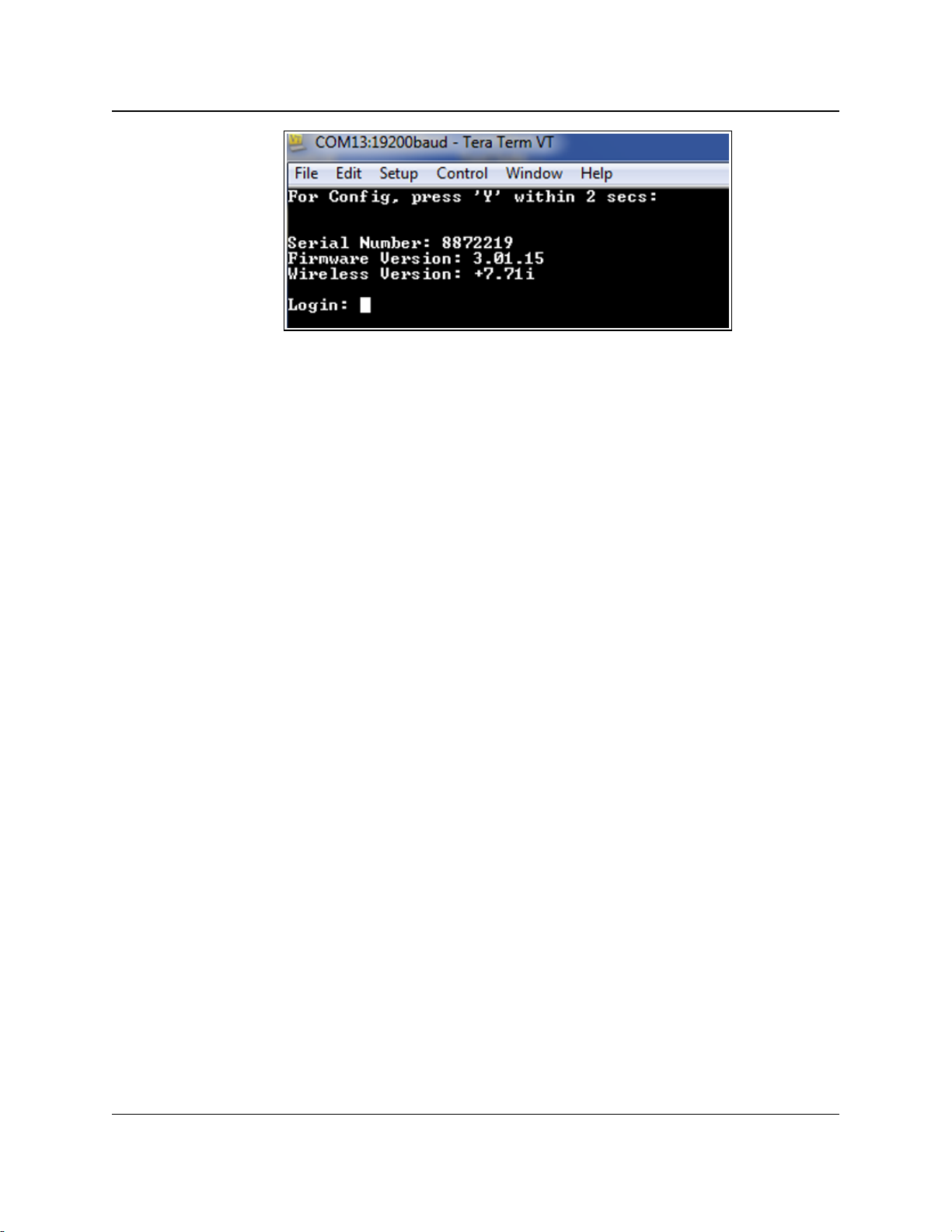
2. Set Up and Program Radios
Figure 28: Example: Tera Term VT window
4. Enter default at the prompt and press <Enter>.
The radio reboots, and all of the radio settings are reset to the factory defaults.
FGR2-P, -PE, & -PE-U
User & Reference Manual
LUM0024AB Rev May-2018 Page 50 of 211 Copyright © 2018FreeWave
This document is the property of FreeWave Technologies, Inc. and contains proprietary information owned by
FreeWave. This document cannot be reproduced in whole or in part by any means without written permission from
FreeWave Technologies, Inc.
Page 51

FGR2-P, -PE, & -PE-U
User & Reference Manual
3. IP and Network
Communication Settings
The parameters on the IP Setup tab or the IP Setup window are typically changed by a Network
Administrator. These are the parameters that set the Ethernet address and other communications
for the radio.
Note: Use the IP Address (on page 53) to change the IP and network communication settings using
the Terminal Menu.
In the IP Setup window, these are the available parameters:
l LAN Network Interface Configuration (Management) - The local area network (LAN)
settings.
l VLAN Configuration (Data) - The virtual local area network (VLAN) settings.
l A VLAN is a group of devices with a common set of requirements that communicate as if
they were attached to the same domain, regardless of their network location.
Note: Not every network needs or uses VLAN IDs.
The VLAN Mode setting is typically set to Disabled.
Changes to VLAN settings should be approved by a network administrator.
l NTP Client - The Network Time Protocol (NTP) settings.
l The device with the IP address entered here is the device that the radios in the network
use to synchronize their internal clocks.
l Syslog Server - The system logging settings.
l Enabling and setting IP addresses in the system server settings instructs the radio to
send all its log entries to a system server.
LUM0024AB Rev May-2018 Page 51 of 211 Copyright © 2018FreeWave
This document is the property of FreeWave Technologies, Inc. and contains proprietary information owned by
FreeWave. This document cannot be reproduced in whole or in part by any means without written permission from
FreeWave Technologies, Inc.
Page 52

3. IP and Network Communication Settings
Default Gateway
Setting Description
Web Parameter: Default Gateway text box in the LAN Network Interface Configuration
(Management) area of the IP Setup window (on page 153).
Terminal Menu: (1) IP Setup > (2) Default Gateway
Network Type: Both
Default Setting: 192.168.111.1
Options: Any valid IPaddress.
Description: The IP address for the appropriate default Gateway.
A network administrator typically sets this parameter.
Note: Putting multiple devices on the network with the same IP address
can cause network problems.
Note: For more information, see Viewing the System Log (on page 103).
FGR2-P, -PE, & -PE-U
User & Reference Manual
3.1. IP Setup Parameter Reference
This section contains the IP setup parameters.
Note: See the Parameter Preference (on page 13) for the parameter table descriptions of the
parameters and controls.
3.1.1. Default Gateway
LUM0024AB Rev May-2018 Page 52 of 211 Copyright © 2018FreeWave
This document is the property of FreeWave Technologies, Inc. and contains proprietary information owned by
FreeWave. This document cannot be reproduced in whole or in part by any means without written permission from
FreeWave Technologies, Inc.
Page 53
IP Address
Setting Description
Web Parameter: IP Address text box in the LAN Network Interface Configuration
(Management) area of the IP Setup window (on page 153).
Terminal Menu: (1) IP Setup > (0) IP Address
Network Type: Both
Default Setting: 192.168.111.100
Options: Any valid IP address.
Description: This is the IPaddress assigned to the radio.
l Each radio in the network is assigned a unique IP address.
l The IP address for each radio must in the proper subnet.
Note: It is possible to have a transparent bridge with an IP address of
255.255.255.255, but serial port functionality, the Security features, and
access to the configuration Web pages is lost.
Caution: Putting multiple devices with the same IP address on the
same network can cause network problems.
l When the VLAN Mode (on page 61) parameter is set to Tagged or Untagged,
this IP information is assigned to the Management portion of the radio (Setup
pages, SNMP, and Discovery Server).
l Any communication with the radio's Web pages, SNMP, or changes made
using the Discovery Server need to be:
l addressed to this IP address and
l tagged with the address in the Management VLAN ID (on page 60)
parameter.
Note: This parameter is hidden in the Configuration Windows when
Global Changes are enabled.
For more information about making global changes, see Use the MultiPoint
Gateway to Change All Connected Radios (on page 33).
3. IP and Network Communication Settings
FGR2-P, -PE, & -PE-U
User & Reference Manual
3.1.2. IP Address
Important!: If using the configurationWeb pages, the system does not validate that the entered IP
address is in the correct 0.0.0.0 format.
Verify the entered IPaddress before sending the setting to the radio.
LUM0024AB Rev May-2018 Page 53 of 211 Copyright © 2018FreeWave
This document is the property of FreeWave Technologies, Inc. and contains proprietary information owned by
FreeWave. This document cannot be reproduced in whole or in part by any means without written permission from
FreeWave Technologies, Inc.
Page 54

3. IP and Network Communication Settings
MTU
Setting Description
Web Parameter: MTU text box in the LAN Network Interface Configuration (Management) area
of the IP Setup window (on page 153)..
Terminal Menu: (1) IPSetup > (5) MTU
Network Type: Both
Default Setting: 1500 bytes
Options: 0 to 1500 bytes
Description: The Maximum Transmission Unit (MTU) is the largest data unit that the radio can
pass via the Ethernet port.
l For TCP, the MTU is the size at which the radio fragments the request into
multiple TCP packets which must be assembled on the remote side for
receipt.
l TCP guarantees complete in-order delivery of traffic where possible.
l The radio attempts to retry sending the packet, with a timeout for each try.
l The radio tries to send portions of the packet or the whole packet if the
packet's size is within the MTU size for each packet sent.
l If pings go through the network but data traffic does not reliably go through,
verify this setting is one to three times the size of what the Maximum
Packet Size parameter setting is for the radio.
FREEWAVE Recommends: With VLANs and some other specific
configurations, TCP/IP traffic can periodically time out over links unless
the MTU parameter is adjusted to be lower than the 1500 byte default
value, with the networks also adjusted accordingly.
FreeWave recommends starting with 1400 bytes in this scenario.
Important!: If the MTU setting is changed, the setting must be changed to
match on all devices within the network.
Caution: Changing this parameter may lead to network instability.
Contact FreeWave Technical Support for guidance about changing
this parameter from the default 1500 bytes.
See Contact FreeWave Technical Support on page 12.
FGR2-P, -PE, & -PE-U
User & Reference Manual
3.1.3. MTU
FREEWAVE Recommends: Leave this setting at its default of 1500 bytes unless networks are run
back-to-back using VLAN tagging (802.1Q trunking, specifically).
LUM0024AB Rev May-2018 Page 54 of 211 Copyright © 2018FreeWave
This document is the property of FreeWave Technologies, Inc. and contains proprietary information owned by
FreeWave. This document cannot be reproduced in whole or in part by any means without written permission from
FreeWave Technologies, Inc.
Page 55

3. IP and Network Communication Settings
NTP Client Enable
Setting Description
Web Parameter: Enable check box in the NTP Client area of the IP Setup window (on page 153).
Terminal Menu: (1) IPSetup > (D) NTP Client
Network Type: Both
Default Setting: Disabled
Options: Disabled, Enabled
Description: Enables the Network Time Protocol (NTP) client on the radio.
l The radio checks with the NTP Server specified in the NTP IP Address (on
page 55) parameter and sets its internal clock to the time and date specified by
the NTP server.
l The radio checks with the NTP server on its initial startup, and then
periodically checks the server to ensure its internal clock is still in sync.
FREEWAVE Recommends: Test the connectivity to the NTP server and
its response to NTP requests. If the radio is unsuccessful connecting to
the NTP server upon booting, it makes a new request to the server before
every log file entry, which can cause unnecessary network traffic.
NTP IP Address
Setting Description
Web Parameter: IP Address text box in the NTP Client area of the IP Setup window (on page
153).
Terminal Menu: (1) IP Setup > (E) NTP IP Address
Network Type: Both
Default Setting: 0.0.0.0
Options: Any valid IP address.
Description: This is the IP address of the NTP server.
Note: If the NTP Client parameter is enabled, the radio checks with this
IP address upon startup to set its internal clock.
3.1.4. NTP Client Enable
FGR2-P, -PE, & -PE-U
User & Reference Manual
3.1.5. NTP IP Address
FreeWave. This document cannot be reproduced in whole or in part by any means without written permission from
LUM0024AB Rev May-2018 Page 55 of 211 Copyright © 2018FreeWave
This document is the property of FreeWave Technologies, Inc. and contains proprietary information owned by
FreeWave Technologies, Inc.
Page 56

3. IP and Network Communication Settings
Push to (Syslog) Server
Setting Description
Web Parameter: Push to Server check box in the Syslog Server area of the IP Setup window (on
page 153).
Terminal Menu: (1) IP Setup > (F) Syslog Server
Network Type: Both
Default Setting: Disabled
Options: l Disabled
l Enabled
Description: Enabling this option instructs the radio to send its log entries to the system logging
server identified in the Syslog Server 1 (on page 58) and Syslog Server 2 (on page
58) text boxes.
Spanning Tree
Setting Description
Web Parameter: Spanning Tree Enable check box in the LAN Network Interface
Configuration (Management) area of the IP Setup window (on page 153).
Terminal Menu: (1) IPSetup > (4) Spanning Tree
Network Type: Both
Default Setting: Disabled
Options: l Disabled
l Enabled
FGR2-P, -PE, & -PE-U
User & Reference Manual
3.1.6. Push to (Syslog) Server
FREEWAVE Recommends: This setting is best setup using the Configuration Windows (on page
151).
3.1.7. Spanning Tree
LUM0024AB Rev May-2018 Page 56 of 211 Copyright © 2018FreeWave
This document is the property of FreeWave Technologies, Inc. and contains proprietary information owned by
FreeWave. This document cannot be reproduced in whole or in part by any means without written permission from
FreeWave Technologies, Inc.
Page 57

3. IP and Network Communication Settings
Spanning Tree
Setting Description
Description: Enabling this parameter causes a Gateway to use the Spanning Tree Protocol
(IEEE 802.1D).
l This protocol eliminates the possibility of the radios creating a network loop,
which can cause network-wide problems.
l Spanning Tree Protocol uses radio bandwidth, as any Spanning Tree radios
are constantly communicating their network location.
Note: Some network devices (e.g., switches and routers), disable a
connection to a device that uses the Spanning Tree Protocol. Prior to
enabling this setting, verify that all network devices work with the
Spanning Tree Protocol.
FREEWAVE Recommends: Leave Spanning Tree disabled, unless the
Spanning Tree Protocol is required.
Subnet Mask
Setting Description
Web Parameter: Subnet Mask text box in the LAN Network Interface Configuration
(Management) area of the IP Setup window (on page 153).
Terminal Menu: (1) IPSetup > (1) Subnet Mask
Network Type: Both
Default Setting: 255.255.255.0
Options: Any valid net mask address in the network.
Description: Used to route data in a sub-network.
l Devices in the same sub network must have addresses in the same subnet to
successfully communicate.
l A Network Administrator typically sets this parameter.
Note: If the default Subnet setting of 255.255.255.0 is used, all devices
within the network MUST have addresses where the first three sections of
the address match, but the last section is unique.
Example: Addresses 10.0.1.201 and 10.0.1.202 are in the same subnet,
but 10.0.2.201 is not included in the subnet. If the subnet mask is set to
255.255.0.0, then only the first two sections must be unique.
FGR2-P, -PE, & -PE-U
User & Reference Manual
3.1.8. Subnet Mask
LUM0024AB Rev May-2018 Page 57 of 211 Copyright © 2018FreeWave
This document is the property of FreeWave Technologies, Inc. and contains proprietary information owned by
FreeWave. This document cannot be reproduced in whole or in part by any means without written permission from
FreeWave Technologies, Inc.
Page 58

3. IP and Network Communication Settings
Syslog Server 1
Setting Description
Web Parameter: Syslog Server 1 text box in the Syslog Server area of the IP Setup window on
page 153.
Terminal Menu: (1) IP Setup > (G) Syslog Server 1 IP
Network Type: Both
Default Setting: 0.0.0.0
Options: Any valid IPaddress.
Description: This is the primary IP address of the system log server.
l If system logging is enabled, the radio sends all log entries to the IP address
entered in this text box.
l The radio sends logs to both server entries, Syslog Server 1 and Syslog
Server 2, concurrently.
Syslog Server 2
Setting Description
Web Parameter: Syslog Sever 2 text box in the Syslog Server area of the IP Setup window on
page 153.
Terminal Menu: (1) IP Setup > (H)Syslog Server 2 IP
Network Type: Both
Default Setting: 0.0.0.0
Options: Any valid IPaddress.
Description: This is the IP address of a second system log server.
l If system logging is enabled, the radio sends all log entries to the IP address
entered in this text box.
l The radio sends logs to both server entries, Syslog Server 1 and Syslog
Server 2, concurrently.
Important!: If a second server does not exist, enter 0.0.0.0.
3.1.9. Syslog Server 1
FGR2-P, -PE, & -PE-U
User & Reference Manual
3.1.10. Syslog Server 2
LUM0024AB Rev May-2018 Page 58 of 211 Copyright © 2018FreeWave
This document is the property of FreeWave Technologies, Inc. and contains proprietary information owned by
FreeWave. This document cannot be reproduced in whole or in part by any means without written permission from
FreeWave Technologies, Inc.
Page 59

3. IP and Network Communication Settings
Data VLAN ID
Setting Description
Web Parameter: Data VLAN ID text box in the VLAN Configuration (Data) area of the IP Setup
window (on page 153).
Terminal Menu: (1)IP Setup > (B) Data VLAN ID
Network Type: Both
Default Setting: 0
Options: Any valid VLAN ID between 1 and 4095.
Description: l Data using this VLAN ID is allowed to:
l come into or be sent out of the radio’s local Ethernet port.
l access the serial ports via the terminal server.
VLAN Default Gateway
Setting Description
Web Parameter: Default Gateway text box in the VLAN Configuration (Data) area of the IP
Setup window (on page 153).
Terminal Menu: (1) IP Setup > (9) Data Default Gateway
Network Type: Both
Default Setting: 192.168.111.1
Options: Any valid IP address.
Description: The IP address for the appropriate default Gateway for the Data VLAN
IPaddress.
A network administrator typically sets this parameter.
3.1.11. Data VLAN ID
Warning! If this parameter needs to be set, contact FreeWave Technical Support for guidance.
Incorrect settings can cause devices in the network to lose communication.
See Contact FreeWave Technical Support (on page 12).
FGR2-P, -PE, & -PE-U
User & Reference Manual
3.1.12. VLAN Default Gateway
Warning! If this parameter needs to be set, contact FreeWave Technical Support for guidance.
Incorrect settings can cause devices in the network to lose communication.
See Contact FreeWave Technical Support (on page 12).
LUM0024AB Rev May-2018 Page 59 of 211 Copyright © 2018FreeWave
This document is the property of FreeWave Technologies, Inc. and contains proprietary information owned by
FreeWave. This document cannot be reproduced in whole or in part by any means without written permission from
FreeWave Technologies, Inc.
Page 60

3. IP and Network Communication Settings
VLAN IP Address
Setting Description
Web Parameter: IP Address text box in the VLAN Configuration (Data) area of the IP Setup
window (on page 153).
Terminal Menu: (1) IP Setup > (7) Data IP Address
Network Type: Both
Default Setting: 192.168.111.100
Options: Any valid IP Address.
Description: When the VLAN Mode is set to Tagged or Untagged, the IP address entered in
this text box is assigned to the Data portion of the radio (Ethernet port traffic and
terminal server communication).
Any data destined for one of the radio's serial ports or its Ethernet port needs to be
addressed to this IP address and tagged with the Data VLAN ID.
Management VLAN ID
Setting Description
Web Parameter: Management VLAN ID text box in the VLAN Configuration (Data) area of the
IP Setup window (on page 153).
Terminal Menu: (1)IP Setup > (A) Management VLAN ID
Network Type: Both
Default Setting: 0
Options: Any valid VLAN ID between 1 and 4095.
Description: Computers and devices using the VLAN ID entered here are able to:
l access the radio’s Setup pages,
l receive SNMP information,
l send SNMP commands, and
l view the radio in the FreeWave Discovery Server.
3.1.13. VLAN IP Address
Warning! If this parameter needs to be set, contact FreeWave Technical Support for guidance.
Incorrect settings can cause devices in the network to lose communication.
See Contact FreeWave Technical Support (on page 12).
FGR2-P, -PE, & -PE-U
User & Reference Manual
3.1.14. Management VLAN ID
Warning! If this parameter needs to be set, contact FreeWave Technical Support for guidance.
Incorrect settings can cause devices in the network to lose communication.
See Contact FreeWave Technical Support (on page 12).
LUM0024AB Rev May-2018 Page 60 of 211 Copyright © 2018FreeWave
This document is the property of FreeWave Technologies, Inc. and contains proprietary information owned by
FreeWave. This document cannot be reproduced in whole or in part by any means without written permission from
FreeWave Technologies, Inc.
Page 61

3. IP and Network Communication Settings
VLAN Mode
Setting Description
Web Parameter: Mode list box in the VLAN Configuration (Data) area of the IP Setup window (on
page 153).
Terminal Menu: (1)IP Setup > (6) VLAN
Network Type: Both
Default Setting: Disabled
Options: Select the applicable option:
l Disabled - VLAN is not used.
l Tagged - If the data coming into the radio’s local Ethernet port is tagged with a
VLAN ID.
l The radio bridges the data, leaving the VLAN ID as-is.
l Untagged - If the data coming into the radio's local Ethernet port is NOT
tagged with a VLAN ID.
l The radio accepts the data, tags it with the VLAN ID entered in the Data
VLAN ID text box, and sends it across the radio link.
Note: Data arriving at this radio and being sent out of the local Ethernet
port has any VLAN tag removed before being sent out of the port.
Description: Determines whether VLAN is active and in which mode it is used.
VLAN Subnet Mask
Setting Description
Web Parameter: Subnet Mask text box in the VLAN Configuration (Data) area of the IP Setup
window (on page 153).
3.1.15. VLAN Mode
Warning! Not every network needs or uses VLAN IDs.
The Mode parameter is typically set to Disabled.
The Network Administrator should approve any changes.
Configuring the VLAN information incorrectly can cause loss of communication between
devices in the network.
FGR2-P, -PE, & -PE-U
User & Reference Manual
3.1.16. VLAN Subnet Mask
Warning! If this parameter needs to be set, contact FreeWave Technical Support for guidance.
Incorrect settings can cause devices in the network to lose communication.
See Contact FreeWave Technical Support (on page 12).
LUM0024AB Rev May-2018 Page 61 of 211 Copyright © 2018FreeWave
This document is the property of FreeWave Technologies, Inc. and contains proprietary information owned by
FreeWave. This document cannot be reproduced in whole or in part by any means without written permission from
FreeWave Technologies, Inc.
Page 62

3. IP and Network Communication Settings
VLAN Subnet Mask
Setting Description
Terminal Menu: (1) IP Setup > (8) Data Subnet Mask
Network Type: Both
Default Setting: 255.255.255.0
Options: Any IPV4 net mask address.
Description: This is the Subnet mask for the Data VLAN IP address.
Example: 255.255.255.0.
VLAN Trunk ID 1 to VLAN Trunk ID 5
Setting Description
Web Parameter: VLAN Trunk ID 1 to VLAN Trunk ID 5 text boxes in the VLAN Configuration
(Data) area of the IP Setup window (on page 153).
Terminal Menu: (1)IP Setup > (C) VLAN Trunk
Network Type: Both
Default Setting: 0
Options: Any number between 1 and 4095.
Description: Use VLANTrunk IDs to propagate the definition of VLANs on the whole local area
network. On each device, enter the VLAN IDs of the devices that radios will be a
participant.
Note: Most networks do not use VLAN trunk IDs.
Web Page Port (http)
Setting Description
Web Parameter: Web Page Port (http) text box in the LAN Network Interface Configuration
(Management) area of the IP Setup window (on page 153).
Terminal Menu: (1)IP Setup > (3) Web Page Port (http)
3.1.17. VLAN Trunk ID 1 to VLAN Trunk ID 5
Warning! If this parameter needs to be set, contact FreeWave Technical Support for guidance.
Incorrect settings can cause devices in the network to lose communication.
See Contact FreeWave Technical Support (on page 12).
FGR2-P, -PE, & -PE-U
User & Reference Manual
3.1.18. Web Page Port (http)
LUM0024AB Rev May-2018 Page 62 of 211 Copyright © 2018FreeWave
This document is the property of FreeWave Technologies, Inc. and contains proprietary information owned by
FreeWave. This document cannot be reproduced in whole or in part by any means without written permission from
FreeWave Technologies, Inc.
Page 63

3. IP and Network Communication Settings
Web Page Port (http)
Setting Description
Network Type: Both
Default Setting: 80
Options: Any valid TCP port from 1 to 65535.
Description: Use this to change the assigned port for the configuration Web pages.
The default setting is port 80, the standard Web page port.
Note: If this setting is changed from port 80, the proper port number MUST
be included when accessing the Setup pages.
Example: http://<IP address>:<Port>, where:
<IP address> is the IP address of the radio and
<Port> is the port number assigned in thisparameter.
If an invalid TCP port is entered, the radio defaults the Web Page Port setting to
80.
FGR2-P, -PE, & -PE-U
User & Reference Manual
LUM0024AB Rev May-2018 Page 63 of 211 Copyright © 2018FreeWave
This document is the property of FreeWave Technologies, Inc. and contains proprietary information owned by
FreeWave. This document cannot be reproduced in whole or in part by any means without written permission from
FreeWave Technologies, Inc.
Page 64

FGR2-P, -PE, & -PE-U
User & Reference Manual
4. Serial Port Settings
Use the settings on the Serial Setup tab or the Serial Setup window to set the serial ports on the
radio. The ports are labeled 1 and 2 on the physical radio. See the radio illustration in Components
of the FGR2-P, -PE, & -PE-U PLUS Radios on page 15.
These parameters are available in Serial Setup:
l Serial Port Mode - This setting defines whether the port acts as a TCP terminal server,
TCP client, UDP client, or Multicast.
l Serial Settings - This setting defines data transmission settings (e.g., Baud Rate and
Flow Control).
l Set these parameters to match the device the port is connected to.
Each serial port is setup independently and configured on its own tab or Configuration Windows.
The ports can have different baud rates, parity, protocol, and so on, but must match the device to
which it is connected. To access either port, a client needs to call the IP address of the radio plus
its assigned port number.
Note: See Viewing the Serial Port Status on page 67 to view the status of each serial port.
4.1. Set the Serial Port Mode
The first parameter is to define the serial port using the:
l MULTICAST Settings.
l TCP Client Settings.
l TCP Server Settings.
l UDP Settings.
LUM0024AB Rev May-2018 Page 64 of 211 Copyright © 2018FreeWave
This document is the property of FreeWave Technologies, Inc. and contains proprietary information owned by
FreeWave. This document cannot be reproduced in whole or in part by any means without written permission from
FreeWave Technologies, Inc.
Page 65

4. Serial Port Settings
FGR2-P, -PE, & -PE-U
User & Reference Manual
Procedure
1. Follow the procedure for Accessing the Configuration Windows (on page 27).
The Status window opens.
2. On the Menu bar, click the serial port to configure (i.e., Serial Port 1 or Serial Port 2).
The applicable Serial Setup window opens.
Figure 29: FGR2-P, -PE, & -PE-U Serial Setup window
3. In one of these areas, click the Enable check box to designate the port as that type:
l TCP Server Settings - Designate the port as a TCP terminal server.
l TCP Client Settings - Designate the port as a TCP client to the IP address and port
entered in the TCP Client IP Address and TCP Client Port text boxes.
l UDP Settings - Designate the radio as a UDP terminal server to the IP address and
port entered in the UDP IP Address and UDP IP Port text boxes.
l MULTICAST Settings - Designate a one-to-many connection from the MultiPoint
Gateway’s serial port to the MultiPoint Repeater’s and/or Endpoint’s serial ports using
the IP address and port entered in the Multicast IP Address and Multicast Port text
boxes.
4.
Click to save the changes.
LUM0024AB Rev May-2018 Page 65 of 211 Copyright © 2018FreeWave
This document is the property of FreeWave Technologies, Inc. and contains proprietary information owned by
FreeWave. This document cannot be reproduced in whole or in part by any means without written permission from
FreeWave Technologies, Inc.
Page 66

4. Serial Port Settings
FGR2-P, -PE, & -PE-U
User & Reference Manual
4.2. Disabling Serial Ports
If a serial port on the radio is not used, it can be disabled.
Note: If both ports are disabled, the Basic IP Setup for the radio still works through Port 1.
Procedure
1. Follow the procedure for Accessing the Configuration Windows (on page 27).
The Status window opens.
2. On the Menu bar, click the serial port to configure (i.e., Serial Port 1 or Serial Port 2).
The applicable Serial Setup window opens.
Figure 30: FGR2-P, -PE, & -PE-U Serial Setup window
3. Clear all the Enable check boxes in the window.
4.
Click to save the changes.
LUM0024AB Rev May-2018 Page 66 of 211 Copyright © 2018FreeWave
This document is the property of FreeWave Technologies, Inc. and contains proprietary information owned by
FreeWave. This document cannot be reproduced in whole or in part by any means without written permission from
FreeWave Technologies, Inc.
Page 67

4. Serial Port Settings
FGR2-P, -PE, & -PE-U
User & Reference Manual
4.3. Viewing the Serial Port Status
Note: The serial port's status is ONLY visible through the Configuration Windows.
This status information is available for each serial port:
l Ethernet (Rx and Tx) (on page 68)
l Serial (Rx and Tx) (on page 68)
l Status (on page 68)
Procedure
1. Follow the procedure for Accessing the Configuration Windows (on page 27).
The Status window opens.
2. On the Menu bar, click the serial port to configure (i.e., Serial Port 1 or Serial Port 2).
The applicable Serial Setup window opens.
Figure 31: FGR2-P, -PE, & -PE-U Serial Setup window
3. Click the Serial Port Status link.
The Serial Port Status window opens.
Note: This window is read-only and cannot be changed.
LUM0024AB Rev May-2018 Page 67 of 211 Copyright © 2018FreeWave
This document is the property of FreeWave Technologies, Inc. and contains proprietary information owned by
FreeWave. This document cannot be reproduced in whole or in part by any means without written permission from
FreeWave Technologies, Inc.
Page 68

4. Serial Port Settings
FGR2-P, -PE, & -PE-U
User & Reference Manual
Figure 32: FGR2-P, -PE, & -PE-U Serial Port Status window
By default, this window updates every 5 seconds.
4. Click the Refresh link to manually refresh the page.
4.3.1. Ethernet (Rx and Tx)
This is the amount of data received (Rx) and transmitted (Tx) from the terminal server to the port.
l Received data indicates data received on the radio via the Ethernet port.
l Transmitted data indicates data sent from the radio out the port.
l The amount is listed in bytes.
4.3.2. Serial (Rx and Tx)
This is the amount of data received (Rx) and transmitted (Tx) from the serial port.
l Received data indicates data coming from the connected device into the serial port.
l Transmitted data indicates data sent out the serial port to the connected device.
l This amount is listed in bytes.
4.3.3. Status
This is the current status of the Terminal Server.
Example: Waiting or Connected.
LUM0024AB Rev May-2018 Page 68 of 211 Copyright © 2018FreeWave
This document is the property of FreeWave Technologies, Inc. and contains proprietary information owned by
FreeWave. This document cannot be reproduced in whole or in part by any means without written permission from
FreeWave Technologies, Inc.
Page 69

4. Serial Port Settings
Multicast Enable
Setting Description
Web Parameter: Enable check box in the MULTICAST Settings area of the Serial Setup window
(on page 168).
Terminal Menu: (2) Serial Setup 1 or (3) Serial Setup 2 > (C) Multicast
Network Type: Both
Default Setting: Disabled
Options: Disabled, Enabled
Description: This setting enables the radio to use Multicast mode when enabled.
l A Multicast is a one-to-many connection from the MultiPoint Gateway’s serial
port to the interested MultiPoint Repeaters and/or Endpoints serial ports.
l In a MultiPoint Gateway, selecting Multicast causes the radio to act as an IP
Multicast Sender on the Multicast address and port.
Multicast IP Address
Setting Description
Web Parameter: Multicast IP text box in the MULTICAST Settings area of the Serial Setup
window (on page 168).
FGR2-P, -PE, & -PE-U
User & Reference Manual
4.4. Serial Port Parameter Reference
This section contains the serial port parameters.
Note: See the Parameter Preference (on page 13) for the parameter table descriptions of the
parameters and controls.
4.4.1. Multicast Enable
4.4.2. Multicast IP Address
LUM0024AB Rev May-2018 Page 69 of 211 Copyright © 2018FreeWave
This document is the property of FreeWave Technologies, Inc. and contains proprietary information owned by
FreeWave. This document cannot be reproduced in whole or in part by any means without written permission from
FreeWave Technologies, Inc.
Page 70

4. Serial Port Settings
Multicast IP Address
Setting Description
Terminal Menu: (2) Serial Setup 1 or (3) Serial Setup 2 > (D) Multicast IP
Network Type: Both
Default Setting: 225.0.0.38
Options: Any valid multicast address from 224.0.0.0 to 239.255.255.255.
Description: This is the IP address used for Multicast if the serial port is set to Multicast mode.
l In a MultiPoint Gateway, this is the sending address.
l In MultiPoint Endpoints and MultiPoint Repeaters, this is the address they
register interest in.
In the Configuration Web pages:
l Enter the IP address in the field to the left of the colon.
l Enter the port number in the field to the right of the colon.
Multicast Port
Setting Description
Web Parameter: The Multicast Port text box in the MULTICAST Settings area of the Serial Setup
window (on page 168).
Terminal Menu: (2) Serial Setup 1 or (3) Serial Setup 2 > (E) Multicast Port
Network Type: Both
Default Setting: Setup 1: 11111
Setup 2: 22222
Options: Any valid port number between 0 and 65535.
Description: The port used if the serial port is set to Multicast mode.
In the Serial Setup window (on page 168), in the MULTICAST Settings area:
l In the Multicast IP text box on the left of the colon, enter the IP address.
l In the Port text box on the right of the colon, enter the port number.
Pre-Packet and Post-Packet Timeouts
Setting Description
Web Parameter: Pre-Packet Timeout (ms) and Post-Packet Timeout (ms) in the RTU Mode
Timing Settings area of the Serial Setup window (on page 168).
4.4.3. Multicast Port
FGR2-P, -PE, & -PE-U
User & Reference Manual
4.4.4. Pre-Packet and Post-Packet Timeouts
LUM0024AB Rev May-2018 Page 70 of 211 Copyright © 2018FreeWave
This document is the property of FreeWave Technologies, Inc. and contains proprietary information owned by
FreeWave. This document cannot be reproduced in whole or in part by any means without written permission from
FreeWave Technologies, Inc.
Page 71

4. Serial Port Settings
Pre-Packet and Post-Packet Timeouts
Setting Description
Terminal Menu: (2) Serial Setup 1 or (3) Serial Setup 2 > (F) Pre Packet Timeout
(2) Serial Setup 1 or (3) Serial Setup 2 > (G) Post Packet Timeout
Network Type: Both
Default Setting: Defaults are based on the data rate selected in the Serial Baud Rate field:
Serial Baud Rate
(bps)
Timeout
(ms)
300 133
600 67
1200 34
2400 17
4800 10
9600 6
19200 4
38400 2
57600 2
115200 1
Options: Any number of milliseconds.
FREEWAVE Recommends: Accept the defaults based on the selected
Serial Baud Rate.
Description: The timeout values are pre-populated when the Modbus RTU parameter is
enabled and are based on the Modbus RTU specification.
Modify the timeout values to account for higher performing Modbus RTU devices.
l If using a non-Modbus device, clear the Modbus RTU Enable check box.
l Both Timeout parameters set to 0, regardless of the selected Baud Rate
(on page 72).
l Set the timeout settings to what the non-Modbus device requires.
Note: As of May-2018, FreeWave only supports Modbus RTU/ASCII.
If a silence-delimited RTU protocol (e.g., the DNP3 protocol) is not used, set both
the Timeout parameters to 0. Any other setting adds additional latencies during
polling.
FGR2-P, -PE, & -PE-U
User & Reference Manual
LUM0024AB Rev May-2018 Page 71 of 211 Copyright © 2018FreeWave
This document is the property of FreeWave Technologies, Inc. and contains proprietary information owned by
FreeWave. This document cannot be reproduced in whole or in part by any means without written permission from
FreeWave Technologies, Inc.
Page 72

4. Serial Port Settings
Runtime Serial Setup "U"
Setting Description
Web Parameter: Runtime Serial Setup "U" check box in the Serial Settings area of the Serial
Setup window (on page 168).
Terminal Menu: (2) Serial Setup 1 or (3) Serial Setup 2 > (O) Runtime Serial Setup
Network Type: Both
Default Setting: Disabled
Options: l Disabled
l Enabled
Description:
If Runtime Serial Setup "U" check box is selected, AND the
computer is connected to the radio using the serial port, press
<Shift+U> to access the Setup Mode without having the radio
reboot.
Baud Rate
Setting Description
Web Parameter: Baud Rate list box in the Serial Settings area of the Serial Setup window (on
page 168).
Terminal Menu: (2) Serial Setup 1 or (3) Serial Setup 2 > (H)Baud Rate
Network Type: Both
Default Setting: 19200
Options: 300, 600, 1200, 2400, 4800, 9600, 19200, 38400, 57600, 115200
4.4.5. Runtime Serial Setup "U"
FGR2-P, -PE, & -PE-U
User & Reference Manual
4.4.6. Baud Rate
LUM0024AB Rev May-2018 Page 72 of 211 Copyright © 2018FreeWave
This document is the property of FreeWave Technologies, Inc. and contains proprietary information owned by
FreeWave. This document cannot be reproduced in whole or in part by any means without written permission from
FreeWave Technologies, Inc.
Page 73

4. Serial Port Settings
Baud Rate
Setting Description
Description: This is the actual baud rate for the radio’s data port.
This setting is the communication rate between the radio and the instrument to
which it is connected, and is independent of the baud rate for the other radios in
the network. It is also independent of the other serial port on the radio.
Set the baud rate to the highest level supported by the device to
which it is connected.
With a poor radio link, however, this may actually result in slower
data communications.
Example: A pair of radios may be used in an application to send data from
remote process instrumentation to the engineer's computer. In this
application, the baud rate for the radio on the instrumentation might be set
to 9600, and the radio on the engineer's computer might be set to 57,600.
Note: The serial ports do not support RFC 2217 level flow control. To
avoid congestion-related data loss, use a link data rate that is at least 2
times higher than the actual data flow rate.
CD Mode
Setting Description
Web Parameter: CD Mode list box in the Serial Settings area of the Serial Setup window (on page
168).
Terminal Menu: (2) Serial Setup 1 or (3) Serial Setup 2 > (M) CDMode
Network Type: Both
Default Setting: Normal
Options: l Normal - CD is asserted when a TCP connection to the associated port is
made, and de-asserted when the TCP connection is closed. Most serial
devices use this option.
l Keyed - CD asserts 500 µs before transmit, and de-asserts 1 ms after the
transmission of the first bit of the last byte of data. This option should be used
with serial devices that require the CD line to be asserted prior to the
transmission of data.
Description: Controls the function of the CD line on the serial port.
FGR2-P, -PE, & -PE-U
User & Reference Manual
4.4.7. CD Mode
LUM0024AB Rev May-2018 Page 73 of 211 Copyright © 2018FreeWave
This document is the property of FreeWave Technologies, Inc. and contains proprietary information owned by
FreeWave. This document cannot be reproduced in whole or in part by any means without written permission from
FreeWave Technologies, Inc.
Page 74

4. Serial Port Settings
Data Bits
Setting Description
Web Parameter: Data Bits list box in the Serial Settings area of the Serial Setup window (on page
168).
Terminal Menu: (2) Serial Setup 1 or (3) Serial Setup 2 > (I)Data Bits
Network Type: Both
Default Setting: 8
Options: 5, 6, 7, 8
Description: The number of data bits the serial port sends.
Note: The setting in this parameter should match the number of data bits
the connected device requires or is setto.
Flow Control
Setting Description
Web Parameter: Flow Control list box in the Serial Settings area of the Serial Setup window (on
page 168).
Terminal Menu: (2) Serial Setup 1 or (3) Serial Setup 2 > (L) Flow Control
Network Type: Both
Default Setting: None
Options: l None - Uses software flow control (XON / XOFF).
l Hardware - Uses hardware flow control (RTS / CTS).
Description: Indicates whether hardware flow control is used on the serial port.
FREEWAVE Recommends: Use Flow Control if using a Baud Rate (on
page 72) higher than 19200.
Interface
Setting Description
Web Parameter: Interface list box in the Serial Settings area of the Serial Setup window (on page
168).
Terminal Menu: (2) Serial Setup 1 or (3) Serial Setup 2 > (N) Interface
4.4.8. Data Bits
4.4.9. Flow Control
FGR2-P, -PE, & -PE-U
User & Reference Manual
4.4.10. Interface
LUM0024AB Rev May-2018 Page 74 of 211 Copyright © 2018FreeWave
This document is the property of FreeWave Technologies, Inc. and contains proprietary information owned by
FreeWave. This document cannot be reproduced in whole or in part by any means without written permission from
FreeWave Technologies, Inc.
Page 75
4. Serial Port Settings
Interface
Setting Description
Network Type: Both
Default Setting: RS232
Options: l RS232
l RS485
l RS422
Description: This is the serial protocol the serial port uses.
This protocol should match the protocol the connected device requires.
Note: For pinout information, see RS422 and RS485 Full Duplex Pinouts
(on page 146).
Modbus RTU
Setting Description
Web Parameter: Modbus RTU Enable check box in the RTU Mode Timing Settings area of the
Serial Setup window (on page 168).
Terminal Menu: Not available
Network Type: Both
Default Setting: Disabled
Options: l Disabled
l Enabled
Description: When enabled, the radio gathers data on the serial port until there is a break (3.5
characters) in the data due to Modbus RTU timing.
l The data is sent as one TCP packet.
l Based on the data rate selected in the Baud Rate (on page 72) parameter, the
system populates the Pre-Packet and Post-Packet Timeouts (on page 70)
parameters with the default number of milliseconds (ms) according to the
Modbus RTU specifications.
Important!: If a silence-delimited RTU protocol (e.g., the DNP3 protocol)
is NOTused, set both the timeout fields to 0.
Any other setting adds additional latencies during polling.
4.4.11. Modbus RTU
FGR2-P, -PE, & -PE-U
User & Reference Manual
LUM0024AB Rev May-2018 Page 75 of 211 Copyright © 2018FreeWave
This document is the property of FreeWave Technologies, Inc. and contains proprietary information owned by
FreeWave. This document cannot be reproduced in whole or in part by any means without written permission from
FreeWave Technologies, Inc.
Page 76

4. Serial Port Settings
Parity
Setting Description
Web Parameter: Parity list box in the Serial Settings area of the Serial Setup window (on page
168).
Terminal Menu: (2) Serial Setup 1 or (3) Serial Setup 2 > (J) Parity
Network Type: Both
Default Setting: None
Options: l Even
l None
l Odd
Description: This is the parity type the serial port uses.
Note: This type should match the parity the connected device requires.
Stop Bits
Setting Description
Web Parameter: Stop Bits list box in the Serial Settings area of the Serial Setup window (on
page 168).
Terminal Menu: (2) Serial Setup 1 or (3) Serial Setup 2 > (K) Stop Bits
Network Type: Both
Default Setting: 1
Options: 1, 2
Description: This is the number of stop bits the serial port sends.
This number should match the number of stop bits the connected device requires.
TCP Client Enable
Setting Description
Web Parameter: Enable check box in the TCP Client Settings area of the Serial Setup window
(on page 168).
Terminal Menu: (2) Serial Setup 1 or (3) Serial Setup 2 > (0) TCP Client
Network Type: Both
4.4.12. Parity
FGR2-P, -PE, & -PE-U
User & Reference Manual
4.4.13. Stop Bits
4.4.14. TCP Client Enable
LUM0024AB Rev May-2018 Page 76 of 211 Copyright © 2018FreeWave
This document is the property of FreeWave Technologies, Inc. and contains proprietary information owned by
FreeWave. This document cannot be reproduced in whole or in part by any means without written permission from
FreeWave Technologies, Inc.
Page 77

4. Serial Port Settings
TCP Client Enable
Setting Description
Default Setting: Disabled
Options: Disabled, Enabled
Description: Enabling this parameter sets the operating mode of the radio's terminal server to
TCP Client.
Your selection determines which other parameters are available for the serial port.
After booting up, the radio creates a persistent outgoing TCP connection to the
TCP Client IP Address on page 77 and TCP Client Port on page 77.
Any data sent to the associated serial port on the radio is automatically directed to
the entered IP address and port number.
TCP Client IP Address
Setting Description
Web Parameter: IP Address text box in the TCP Client Settings area of the Serial Setup window
(on page 168).
Terminal Menu: (2) Serial Setup 1 or (3) Serial Setup 2 > (4) Client IP
Network Type: Both
Default Setting: 0.0.0.0
Options: Any valid IP address.
Description: This is the IP address the radio creates a connection to on boot-up, when the radio
is set to TCP Client mode.
In the Configuration Web page:
l Enter the IP address to the left of the colon.
l Enter the TCP port number in the box to the right of the colon.
TCP Client Port
Setting Description
Web Parameter: Port text box in the TCP Client Settings area of the Serial Setup window (on
page 168).
Terminal Menu: (2) Serial Setup 1 or (3) Serial Setup 2 > (5) Client Port
Network Type: Both
Default Setting: Setup 1: 9000
Setup 2: 9001
4.4.15. TCP Client IP Address
FGR2-P, -PE, & -PE-U
User & Reference Manual
4.4.16. TCP Client Port
LUM0024AB Rev May-2018 Page 77 of 211 Copyright © 2018FreeWave
This document is the property of FreeWave Technologies, Inc. and contains proprietary information owned by
FreeWave. This document cannot be reproduced in whole or in part by any means without written permission from
FreeWave Technologies, Inc.
Page 78

4. Serial Port Settings
TCP Client Port
Setting Description
Options: Any valid port number between 0 and 65335.
Description: This is the port number the radio creates a connection to on boot-up, when the
radio is set to TCP Client mode.
In the Configuration Web page:
l Enter the IP address to the left of the colon.
l Enter the TCP port number in the box to the right of the colon.
TCP Server Enable
Setting Description
Web Parameter: Enable check box in the TCP Server Settings area of the Serial Setup window
(on page 168).
Terminal Menu: (2) Serial Setup 1 or (3) Serial Setup 2 > (0) TCP Server
Network Type: Both
Default Setting: Enabled
Options: l Disabled
l Enabled
Description: Enabling this parameter sets the operating mode of the radio's terminal server to
TCP Server.
l The selection determines which other parameters are available for the serial
port.
l TCP establishes a connection at both ends of the communication between
two machines before any data can be transmitted.
l The TCP Server waits for calls from a TCP client.
l If there are multiple TCP Clients set up to communicate with the TCP Server,
after a request comes into the TCP Server port, the radio sends any incoming
serial data to the IP address of the requesting device.
l The radio continues doing so until a new device makes a request on that port.
l The radio always sends the serial data to the address of the last successful
requesting device.
4.4.17. TCP Server Enable
FGR2-P, -PE, & -PE-U
User & Reference Manual
FreeWave. This document cannot be reproduced in whole or in part by any means without written permission from
LUM0024AB Rev May-2018 Page 78 of 211 Copyright © 2018FreeWave
This document is the property of FreeWave Technologies, Inc. and contains proprietary information owned by
FreeWave Technologies, Inc.
Page 79

4. Serial Port Settings
TCP Server Inactivity Timeout
Setting Description
Web Parameter: Inactivity Timeout (Seconds) text box in the TCP Server Settings area of the
Serial Setup window (on page 168).
Terminal Menu: (2) Serial Setup 1 or (3) Serial Setup 2 > (2) Inactivity Timeout
Network Type: Both
Default Setting: 0
Options: Any number of seconds.
Description: This setting controls how long, in seconds, an incoming TCP connection must be
idle (that is, no data being transferred) before the radio drops the connection.
A setting of 0 means that the radio never disconnects an idle connection—all
disconnects need to come from the client.
FREEWAVE Recommends: In some RTUs, after the RTU is connected
to the radio as a client, the RTU does not properly disconnect the TCP
session. To help overcome this potential behavior of some RTUs,
FreeWave recommends setting the Inactivity Timeout parameter to 10.
TCP Server Keep Alive
Setting Description
Web Parameter: TCP Server Keep Alive check box in the TCP Server Settings area of the Serial
Setup window (on page 168).
Terminal Menu: Not available
Network Type: Both
Default Setting: Disabled
Options: Disabled, Enabled
Description: If enabled, the radio sends a packet at a regular interval to ensure the route used
for an Ethernet session is kept for the entire session.
If there is no data or keep alive packets, routers can lose their current session and
the packets can travel a different route through the TCP network.
4.4.18. TCP Server Inactivity Timeout
FGR2-P, -PE, & -PE-U
User & Reference Manual
4.4.19. TCP Server Keep Alive
LUM0024AB Rev May-2018 Page 79 of 211 Copyright © 2018FreeWave
This document is the property of FreeWave Technologies, Inc. and contains proprietary information owned by
FreeWave. This document cannot be reproduced in whole or in part by any means without written permission from
FreeWave Technologies, Inc.
Page 80

4. Serial Port Settings
TCP Server Port
Setting Description
Web Parameter: Port text box in the TCP Server Settings area of the Serial Setup window (on
page 168).
Terminal Menu: (2) Serial Setup 1 or (3) Serial Setup 2 > (1) TCP Server Port
Network Type: Both
Default Setting: Setup 1: 7000
Setup 2: 7001
Options: Any valid TCP port between 0 and 65535.
Description: The TCP port the radio listens to for incoming TCP connections.
UDP Enable
Setting Description
Web Parameter: Enable check box in the UDP Settings area of the Serial Setup window (on page
168).
Terminal Menu: (2) Serial Setup 1 or (3) Serial Setup 2 > (9) UDP
Network Type: Both
Default Setting: Disabled
Options: Disabled, Enabled
Description: This setting enables the radio as a UDP terminal server using the port number
entered in the destination port.
If using as a UDP terminal server, the port number entered in the destination port
is the UDP port that the radio listens to for requests.
UDP IP Address
Setting Description
Web Parameter: IP Address text box in the UDP Settings area of the Serial Setup window (on
page 168).
Terminal Menu: (2) Serial Setup 1 or (3) Serial Setup 2 > (A) UDP IP
Network Type: Both
Default Setting: 0.0.0.0
Options: Any valid Multicast address from 224.0.0.0 to 239.255.255.255.
4.4.20. TCP Server Port
4.4.21. UDP Enable
FGR2-P, -PE, & -PE-U
User & Reference Manual
4.4.22. UDP IP Address
LUM0024AB Rev May-2018 Page 80 of 211 Copyright © 2018FreeWave
This document is the property of FreeWave Technologies, Inc. and contains proprietary information owned by
FreeWave. This document cannot be reproduced in whole or in part by any means without written permission from
FreeWave Technologies, Inc.
Page 81

4. Serial Port Settings
UDP IP Address
Setting Description
Description: When the serial port is set to UDP mode, enter the IPaddress where the radio
sends any serial data coming into its serial port.
1. Enter the IP address to the left of the colon.
2. Enter the port number in the box to the right of the colon.
UDP IP Port
Setting Description
Web Parameter: Port text box in the UDP Settings area of the Serial Setup window (on page
168).
Terminal Menu: (2) Serial Setup 1 or (3) Serial Setup 2 > (B) UDP Port
Network Type: Both
Default Setting: Setup 1: 6000
Setup 2: 6001
Options: Any valid IP port number between 0 and 65535.
Description: This is the destination port that the radio listens to for requests.
4.4.23. UDP IP Port
FGR2-P, -PE, & -PE-U
User & Reference Manual
LUM0024AB Rev May-2018 Page 81 of 211 Copyright © 2018FreeWave
This document is the property of FreeWave Technologies, Inc. and contains proprietary information owned by
FreeWave. This document cannot be reproduced in whole or in part by any means without written permission from
FreeWave Technologies, Inc.
Page 82

FGR2-P, -PE, & -PE-U
User & Reference Manual
5. Radio Settings
Use the settings on the Radio Setup window (on page 156) to set the general functioning of the
radio.
The available parameters are:
l Operation Mode - Designates the mode the radio uses to communicate and the
networktype.
l Transmission Characteristics - Transmission characteristics (e.g., Frequency Key and
the packet size parameters) are for advanced users only.
Important!: It is critical to understand the principles of RF data transmission to change these
parameters.
l Point-to-Point - The Transmit Rate and the Call Book are mainly for use in a Point-to-
Point network.
Note: See the Call Book window on page 158.
l Multipoint Parameters - A Point-to-MultiPoint network requires that several parameters
are set consistently on all radios in the network. This includes RF Data Rate, Min and Max
Packet Size, and Frequency Key.
Important!: If several independent, PTMP networks are located in close proximity, it is very
important to include as much frequency and time diversity as possible using different
Frequency Key and Min and Max Packet Sizes.
In a Point-to-Point network, the Gateway determines all settings in an Endpoint or Repeater,
except for the Transmit Power and Retry Timeout. All other settings in a Point-to-Point network
are determined by the Gateway's settings.
LUM0024AB Rev May-2018 Page 82 of 211 Copyright © 2018FreeWave
This document is the property of FreeWave Technologies, Inc. and contains proprietary information owned by
FreeWave. This document cannot be reproduced in whole or in part by any means without written permission from
FreeWave Technologies, Inc.
Page 83

5. Radio Settings
Addressed Repeat
Setting Description
Web Parameter: Addressed Repeat list box in the MultiPoint Parameters area of the Radio
Setup window (on page 156).
Terminal Menu: (4) Radio Setup > (A) Addressed Repeat
Network Type: MultiPoint
Default Setting: 3
Options: Any number between 0 and 9.
Description: In a MultiPoint network where the Repeaters parameter is set to Disabled, most
packets from the Gateway are addressed to a specific MAC address. This
addressing allows the destination device to send an acknowledgment back to the
Gateway that the packet was received successfully.
The Addressed Repeat parameter determines the maximum number of times the
Gateway repeats its data packet if it does not receive an acknowledgment from
the destination device.
l This repeat is a smart repeat - the Gateway only repeats its data if it does
not receive an acknowledgment.
l Changing this setting to a higher number can increase the reliability of
weaker radio links while keeping the maximum possible throughput for that
link.
In Endpoints, this setting determines how many times the Endpoint retries a
packet of addressed data before taking the action set in the Slave Connect Odds
parameter.
Caution: Changes made to the radio settings can cause the radios to lose communication with
the Gateway and Multipoint Repeaters.
Use caution when making global changes using the Global Change function.
For more information about making global changes, see Use the MultiPoint Gateway to Change
All Connected Radios (on page 33).
FGR2-P, -PE, & -PE-U
User & Reference Manual
5.1. Radio Setup Parameter Reference
This section contains the radio setup parameters.
Note: See the Parameter Preference (on page 13) for the parameter table descriptions of the
parameters and controls.
5.1.1. Addressed Repeat
Note: This setting MUST match between the Gateway and all Repeaters.
LUM0024AB Rev May-2018 Page 83 of 211 Copyright © 2018FreeWave
This document is the property of FreeWave Technologies, Inc. and contains proprietary information owned by
FreeWave. This document cannot be reproduced in whole or in part by any means without written permission from
FreeWave Technologies, Inc.
Page 84

5. Radio Settings
Broadcast Repeat
Setting Description
Web Parameter: Broadcast Repeat list box in the MultiPoint Parameters area of the Radio Setup
window (on page 156).
Terminal Menu: (4)Radio Setup > (B) Broadcast Repeat
Network Type: MultiPoint
Default Setting: 3
Options: Any number between 0 and 9.
Description: In Endpoints, this setting determines how many times the Endpoint retries a
packet of broadcast data before taking the action set in the Slave Connect Odds
(on page 98) parameter.
The Broadcast Repeat parameter may be set to 0 in the Gateway if the software
is capable of or requires acknowledgment. In this case, if the Gateway sends a
packet that the Endpoint does not receive, the software controls the retries, as
needed.
l For networks with solid RF links, this parameter should be set to a low
value such as 1 or 2.
l If a network has some weak or marginal links, this parameter should be set
to higher values.
l If an Endpoint receives a good packet from a Gateway more than once, it
discards the repeated packets.
l Similarly, after a MultiPoint Repeater receives a good packet from the
Gateway more than once, it discards any further repeated packets.
l In turn, the Repeater sends the packet out to the next Repeater or Endpoint
(s) the number of times corresponding to its own Broadcast Repeat
parameter setting.
In a network that contains radios set as a Repeater, all packets from the Gateway
are considered broadcast MAC address packets.
Increasing the Broadcast Repeat parameter setting in this type of
network increases the probability of a packet getting through.
It also increases latency and decreases Gateway-to-Repeater and
Gateway-to-Endpoint throughput in the network because each
packet from the Gateway or Repeater is being sent multiple times.
Important!: Find the optimal mix between network robustness,
throughput, and latency.
In general, a setting of 2 to 3 works well for most well designed networks.
FGR2-P, -PE, & -PE-U
User & Reference Manual
5.1.2. Broadcast Repeat
Note: This setting MUST match between the Gateway and all Repeaters.
LUM0024AB Rev May-2018 Page 84 of 211 Copyright © 2018FreeWave
This document is the property of FreeWave Technologies, Inc. and contains proprietary information owned by
FreeWave. This document cannot be reproduced in whole or in part by any means without written permission from
FreeWave Technologies, Inc.
Page 85

5. Radio Settings
Frequency Key
Setting Description
Web Parameter: Frequency Key list box in the Transmission Characteristics area of the Radio
Setup window (on page 156).
Terminal Menu: (4) Radio Setup > (2) Frequency Key
Network Type: Both
Default Setting: 5
Options: Any number between 0 to 9, or any letter between A to E.
FGR2-P, -PE, & -PE-U
User & Reference Manual
5.1.3. Broadcast Repeat in MultiPoint Networks with Repeaters
The Broadcast Repeat parameter must also be set in MultiPoint Repeaters because a Repeater
appears as a Gateway to an Endpoint.
Therefore, the Repeater sends the packet out the number of times corresponding to its own
Broadcast Repeat parameter setting. If this parameter is set improperly, the reliability of the
overall network may be diminished.
Example: If a Gateway's Broadcast Repeat parameter is set to 3, the link between the Gateway
and Repeater should be robust.
If the Repeater's Broadcast Repeat parameter is set to 0, this could cause marginal communication
between the Repeater and the Endpoints.
The Endpoints communicating through this Repeater only receives the initial packet from the
Gateway with no repeats.
Therefore, if the packet is not received on the first try, the Endpoint does not respond as expected.
Important!: This parameter should NEVER be set higher on a Repeater than on its Gateway.
5.1.4. Frequency Key
Note: If subnet IDs are not used to route network traffic, the Frequency Key must match on all
radios in the network.
LUM0024AB Rev May-2018 Page 85 of 211 Copyright © 2018FreeWave
This document is the property of FreeWave Technologies, Inc. and contains proprietary information owned by
FreeWave. This document cannot be reproduced in whole or in part by any means without written permission from
FreeWave Technologies, Inc.
Page 86

5. Radio Settings
Frequency Key
Setting Description
Description: This setting changes the hopping patterns of the radio.
l There are 15 choices available for the Frequency Key parameter
representing 15 different pseudo-random hop patterns.
l These hopping patterns minimize the interference with other FreeWave
radios operating in the area.
Example: If there were 10 pairs of FreeWave radios operating on different
networks in close proximity, setting a different Frequency Key value for
each pair reduces the chance that radios hop to the same frequency at the
same time.
If two networks were to hop to the same frequency by chance, the next
hop would be to a different frequency for both networks.
To use a different Frequency Key, subnet IDs MUST be used.
Note: See Subnet ID on page 99.
Additional network separation can be gained by adjusting the Max
and Min Packet Size settings.
Frequency Zones
Setting Description
Web Parameter: Zones check boxes in the Transmission Characteristics area of the Radio
Setup window (on page 156).
Terminal Menu: (4)Radio Setup > (3) Zones
Network Type: Both
Default Setting: All selected
Note: HTP-900RE-SR004 and HTP-900SEO-SR004 models are
configured to limit frequencies to 915 MHz to 927 MHz.
FGR2-P, -PE, & -PE-U
User & Reference Manual
5.1.5. Frequency Zones
Important!: When trying to inter-operate and there are radios with different Country Codes on the
Status window (on page 175), contact FreeWave Customer Support for assistance.
See Contact FreeWave Technical Support on page 12.
Note: In MultiPoint networks, this setting only needs to be set on the Gateway. In a Point-to-Point
network, the Gateway and the Endpoint must have matching Frequency Zone settings.
FreeWave. This document cannot be reproduced in whole or in part by any means without written permission from
LUM0024AB Rev May-2018 Page 86 of 211 Copyright © 2018FreeWave
This document is the property of FreeWave Technologies, Inc. and contains proprietary information owned by
FreeWave Technologies, Inc.
Page 87

5. Radio Settings
Frequency Zones
Setting Description
Options: See Description.
Description: In the Radio Setup window, the zones are listed as check boxes in the Zones box
in the Transmission Characteristics area.
Select the check box next to the zone to enable it.
Important!: A cleared check box indicates the radio does NOT use that
frequency.
This setting divides the available band into smaller bands (i.e., 16 smaller bands
each consisting of 2 or 3 frequency channels):
l 902 MHz to 928 MHz
l The zones listed are in MHz.
l The radio requires at least one zone active to operate.
Master Tx Beacon
Setting Description
Web Parameter: Master Tx Beacon list box in the MultiPoint Parameters area of the Radio Setup
window (on page 156).
Terminal Menu: (4)Radio Setup > (E) Master Tx Beacon
Network Type: MultiPoint
Default Setting: 1
Options: Any number between 1 and 9.
Description: This setting controls the Gateway's duty-cycle during idle times.
l By default, the Gateway transmits every frame, whether there is payload
data or not.
l Selecting a number larger than 1 in this parameter causes the Gateway to
skip that number of transmit frames when it has no other data to send.
l This skip can reduce the power usage from the Gateway during idle
times.
l If data does come into the Gateway, the Gateway transmits that data
regardless of this setting.
Note: In a network that has the Repeaters parameter set to Enabled, this
parameter must be set to 1.
5.1.6. Master Tx Beacon
FGR2-P, -PE, & -PE-U
User & Reference Manual
Note: This setting MUST to be the same in every Gateway, Repeater, and Endpoint.
LUM0024AB Rev May-2018 Page 87 of 211 Copyright © 2018FreeWave
This document is the property of FreeWave Technologies, Inc. and contains proprietary information owned by
FreeWave. This document cannot be reproduced in whole or in part by any means without written permission from
FreeWave Technologies, Inc.
Page 88

5. Radio Settings
Max Packet Size and Min Packet Size
Setting Description
Web Parameter: Max Packet Size and Min Packet Size list boxes in the Transmission
Characteristics area of the Radio Setup window (on page 156).
Terminal Menu: (4) Radio Setup > (4) Max Packet Size
(4) Radio Setup > (5) Min Packet Size
Network Type: Both
Default Setting: l Max Packet Size = 9
l Min Packet Size = 1
Use these settings for the overall best throughput.
Options: Any number between 0 and 9.
Description: The Max and Min Packet Size settings and the RF Data Rate determine the
number of bytes in the packets.
l Throughput can be enhanced when packet sizes are optimized.
l In Point-to-Point mode, the Max and Min Packet Size parameter settings
do not have material impact on throughput unless a data rate of 92 kbps is
applicable.
This may have an impact on latency.
Example: If small amounts of data are sent and large packet sizes are
selected, there would be a certain amount of time “wasted” between each
packet.
Minimum Packet Size Definition
Minimum Setting
Min Packet Size (bytes)
RF Data rate = 154 kbps
Min Packet Size (bytes)
RF Data Rate = 115 kbps
0 15 8
FGR2-P, -PE, & -PE-U
User & Reference Manual
5.1.7. Max Packet Size and Min Packet Size
Note: In MultiPoint networks, the Max Packet Size and Min Packet Size must be identical in all
radios.
In Point-to-Point networks the Gateway’s settings take precedence over the Endpoint.
This table defines the minimum packet size (in bytes) of the Min Packet Size setting versus the
RF Data Rate setting.
Note: Using the default settings, the actual minimum packet size for the radios, in bytes, is 21.
LUM0024AB Rev May-2018 Page 88 of 211 Copyright © 2018FreeWave
This document is the property of FreeWave Technologies, Inc. and contains proprietary information owned by
FreeWave. This document cannot be reproduced in whole or in part by any means without written permission from
FreeWave Technologies, Inc.
Page 89

5. Radio Settings
Minimum Packet Size Definition
Minimum Setting
Min Packet Size (bytes)
RF Data rate = 154 kbps
Min Packet Size (bytes)
RF Data Rate = 115 kbps
1 21 12
2 26 16
3 31 20
4 37 24
5 42 28
6 47 32
7 53 36
8 58 40
9 63 44
Maximum Packet Size Definition with RF Data Rate of 154 kbps (in bytes)
Max Setting (blank area = not recommended)
Minimum
Setting
0 1 2 3 4 5 6 7 8 9
0 165 186 207
1 170 191 213
2 154 175 197 218
3 159 181 202 223
4 165 186 207 229
5 170 191 213 234
6 154 175 197 218 239
7 159 181 202 223 245
8 165 186 207 229 250
9 170 191 213 234 255
FGR2-P, -PE, & -PE-U
User & Reference Manual
This table defines the maximum packet size (in bytes) of the Min Packet Size setting versus the
Max Packet Size setting where the RF Data Rate is set to 154 kbps.
Note: Using the default settings, the actual maximum packet size, in bytes, is 213.
Referencing the default settings, the Gateway transmits a maximum of 213 bytes on every hop. If
fewer than 213 bytes are transmitted by the Gateway, the balance is allocated to the Endpoint's
transmission, plus the quantity in the Min Packet Size setting.
LUM0024AB Rev May-2018 Page 89 of 211 Copyright © 2018FreeWave
This document is the property of FreeWave Technologies, Inc. and contains proprietary information owned by
FreeWave. This document cannot be reproduced in whole or in part by any means without written permission from
FreeWave Technologies, Inc.
Page 90

5. Radio Settings
Maximum Packet Size Definition with RF Data Rate of 115 kbps (in bytes)
Max Setting (blank area = not recommended)
Minimum
Setting
0 1 2 3 4 5 6 7 8 9
0
88 104 120 136
152
1
92 108 124 140
156
2
80 96 112 128 144
160
3
84 100 116 132 148
164
4
88 104 120 136 152
168
5
92 108 124 140 156
172
6
80 96 112 128 144 160
176
7
84 100 116 132 148 164
180
8
88 104 120 136 152 168
184
9
92 108 124 140 156 172
188
Modem Mode
Setting Description
Web Parameter: Modem Mode list box in the Operation Mode are of the Radio Setup window (on
page 156).
Terminal Menu: (4) Radio Setup > (1) Modem Mode
Network Type: Both
Default Setting: Gateway in software earlier than 2.30
MultiPoint Endpoint in software 2.30 and later
Options: See Modem Mode Options (on page 91).
Example: If a Gateway transmits 100 bytes, the Endpoint then has a total of 134 bytes available
[113 (leftover bytes) + 21 (Min Packet Size)].
FGR2-P, -PE, & -PE-U
User & Reference Manual
This table defines the maximum packet size (in bytes) of the Min Packet Size setting versus the
Max Packet Size setting where the RF Data Rate is set to 115 kbps .
5.1.8. Modem Mode
LUM0024AB Rev May-2018 Page 90 of 211 Copyright © 2018FreeWave
This document is the property of FreeWave Technologies, Inc. and contains proprietary information owned by
FreeWave. This document cannot be reproduced in whole or in part by any means without written permission from
FreeWave Technologies, Inc.
Page 91

5. Radio Settings
Modem Mode
Setting Description
Description: The Network Type and Modem Mode options designate the method FreeWave
radios use to communicate with each other. FreeWave Ethernet radios operate in
a Gateway-to-Endpoint configuration. Before the radios can operate together, they
must be set up to properly communicate.
l In a standard configuration, the Gateway mode should be used on the end
which will be connected to the LAN.
l When setting up the radio, remember that a number of parameters are
controlled by the settings in the Gateway.
l Therefore, deploying the Gateway on the communications end where it is
easier to access is strongly advised.
Note: This parameter is hidden in the Configuration Windows when
Global Changes are enabled.
For more information about making global changes, see Use the MultiPoint
Gateway to Change All Connected Radios (on page 33).
Modem Mode Options
Operation Mode Description
Point-to-Point
Gateway
Designates the radio as the Gateway in Point-to-Point mode.
l The Gateway may call any or all Endpoints designated in its Call Book.
l A quick method of identifying a Gateway is to power the radio.
Note: Prior to establishing a communication link with an Endpoint or
Repeater, all three of the Gateway’s lower LEDs (CD, TX, CTS) are solid
red ( ).
Point-to-Point
Endpoint
Designates the radio as an Endpoint in Point-to-Point mode.
The Endpoint communicates with any Gateway in its Call Book, either directly or
through up to four Repeaters.
Note: When functioning as an Endpoint, the Entry to Call feature in the
radio’s Call Book is not operational.
FGR2-P, -PE, & -PE-U
User & Reference Manual
Modem Mode Options
Repeaters are commonly used in serial networks to connect long distances, but not in Ethernet
networks. If the network topology requires a Repeater to connect radios over greater distances,
use a back-to-back Repeater where data is repeated over a wire instead of over the air. This
preserves throughput.
LUM0024AB Rev May-2018 Page 91 of 211 Copyright © 2018FreeWave
This document is the property of FreeWave Technologies, Inc. and contains proprietary information owned by
FreeWave. This document cannot be reproduced in whole or in part by any means without written permission from
FreeWave Technologies, Inc.
Page 92

5. Radio Settings
Modem Mode Options
Operation Mode Description
MultiPoint
Gateway
Designates the radio as a Gateway in MultiPoint mode.
l This mode allows one Gateway radio to simultaneously be in
communication with numerous Endpoints and Repeaters.
l A MultiPoint Gateway communicates only with other radios designated as
MultiPoint Endpoints or MultiPoint Repeaters.
MultiPoint
Endpoint
Designates the radio as an Endpoint in MultiPoint mode.
l This mode allows the Endpoint to communicate with a MultiPoint Gateway.
l The Endpoint may communicate with its Gateway through one or more
Repeaters.
Point-to-Point
Repeater
(Single Radio
Repeater)
FreeWave allows the use of a maximum four (4) Repeaters in a Point-to-Point
communications link, significantly extending the operating range.
l When designated as a Point-to-Point Repeater, a radio behaves as a pass-
through link.
l All settings for the baud rates and RF transmission characteristics are
disabled.
l A Repeater connects with any Gateway that calls it.
l The Repeater must be set up properly in the Gateway's Call Book.
l In Point-to-Point mode, the Repeater is NOT an Endpoint/Repeater.
l The Call Book MUST be set in Point-to-Point mode.
Note: This operation mode should be used when operating the radio as a
terminal server only (no RF connectivity).
Important!: Adding a Repeater to a network cuts the network throughput
by 50%.
Note: For more information, see the Call Book window (on page 158).
MultiPoint
Repeater
(Single Radio
Repeater)
Allows the radio to operate as an Endpoint/Repeater in a MultiPoint network.
Important!: Some advanced features of the radio do NOT operate in
networks containing Repeaters. FreeWave does not recommend the use
of single-radio Repeaters.
Important!: Adding a Repeater to a network cuts the network throughput
by 50%.
Any Repeater in a Point-to-MultiPoint network is an Endpoint/Repeater.
FGR2-P, -PE, & -PE-U
User & Reference Manual
LUM0024AB Rev May-2018 Page 92 of 211 Copyright © 2018FreeWave
This document is the property of FreeWave Technologies, Inc. and contains proprietary information owned by
FreeWave. This document cannot be reproduced in whole or in part by any means without written permission from
FreeWave Technologies, Inc.
Page 93

5. Radio Settings
Network ID
Setting Description
Web Parameter: Network ID text box in the MultiPoint Parameters area of the Radio Setup
window (on page 156).
Terminal Menu: (4)Radio Setup > (F)Network ID
Network Type: MultiPoint
Default Setting: l 255 in software earlier than 2.30.
l 1 in software 2.30 and later.
Options: Any number between 0 and 4095.
Description: Use the Network ID to establish MultiPoint networks without using the Call Book.
l To enable the Network ID, the value must be set between 0 and 4095
(excluding 255, which disables the Network ID and enables the Call Book).
l Because the Network ID does not use serial numbers, MultiPoint Gateways
and Repeaters may be replaced without reconfiguring all of the Endpoints in
the network.
l An Endpoint links with the first Gateway or Repeater that it hears that has a
matching Network ID.
l The Network ID should be used in conjunction with the Subnet ID feature (if
necessary) to route data through the radio network.
l Without having the serial numbers in the Call Book, Endpoints may establish
communications with different Masters, though not at the same time.
l This is very useful in mobile MultiPoint applications.
FREEWAVE Recommends: A Network ID of four characters.
Example: The last four digits of the Gateway's serial number.
Using the last four digits of the Gateway's serial number, if it is
below 4095, helps to ensure the Network ID is unique and does not
overlap with other nearby FreeWave networks.
Caution: Avoid using numbers that coincide with nearby landmarks
or highways.
5.1.9. Network ID
FGR2-P, -PE, & -PE-U
User & Reference Manual
LUM0024AB Rev May-2018 Page 93 of 211 Copyright © 2018FreeWave
This document is the property of FreeWave Technologies, Inc. and contains proprietary information owned by
FreeWave. This document cannot be reproduced in whole or in part by any means without written permission from
FreeWave Technologies, Inc.
Page 94

5. Radio Settings
Network Type
Setting Description
Web Parameter: Network Type list box in the Operation Mode are of the Radio Setup window (on
page 156).
Terminal Menu: (4) Radio Setup > (0) Network Type
Network Type: Both
Default Setting: l Point-to-Point in software earlier than 2.30.
l Point-to-MultiPoint in software 2.30 and later.
Options: MultiPoint, Point-to-Point
Description: This setting indicates the type of network the radio resides in. This selection and
the selection in the Modem Mode parameter determine the operation mode of the
radio (e.g., a Point-to-Point Gateway).
Note: For descriptions of each network type and modem mode
combination, see Modem Mode on page 90.
Important!: The network type MUST match for all radios in a network.
Example: If configuring a Point-to-MultiPoint network, verify the Network
Type selection for each radio in the network is MultiPoint.
Note: This parameter is hidden in the Configuration Windows when
Global Changes are enabled.
For more information about making global changes, see Use the MultiPoint
Gateway to Change All Connected Radios (on page 33).
Repeaters
Setting Description
Web Parameter: Repeaters list box in the MultiPoint Parameters area of the Radio Setup window
(on page 156).
Terminal Menu: (4) Radio Setup > (G) Repeaters
Network Type: MultiPoint
Default Setting: Disabled
Options: l Disabled
l Enabled
5.1.10. Network Type
FGR2-P, -PE, & -PE-U
User & Reference Manual
5.1.11. Repeaters
LUM0024AB Rev May-2018 Page 94 of 211 Copyright © 2018FreeWave
This document is the property of FreeWave Technologies, Inc. and contains proprietary information owned by
FreeWave. This document cannot be reproduced in whole or in part by any means without written permission from
FreeWave Technologies, Inc.
Page 95

5. Radio Settings
Repeaters
Setting Description
Description:
Important!: In a MultiPoint network, it is critical to transmission timing to
configure this parameter correctly.
l Set to Disabled if there are no Repeaters in the network.
l Set to Enabled if any number of Repeaters exist in the network.
Important!: Many advanced features of the FGR2-P, -PE, & -PE-U PLUS
Radio are restricted in networks where the Repeaters parameter is set to
Enabled.
Note: For best operation, FreeWave does NOT recommend the use of
single-radio Repeaters.
Retry Timeout
Setting Description
Web Parameter: Retry Timeout list box in the Transmission Characteristics area of the Radio
Setup window (on page 156).
Terminal Menu: (4) Radio Setup > (7) Retry Timeout
Network Type: Both
Default Setting: 255
Options: Any number between 8 and 255 in MultiPoint networks.
Any number between 151 and 255 in Point-to-Point networks.
5.1.12. Retry Timeout
FGR2-P, -PE, & -PE-U
User & Reference Manual
Important!: While intended primarily for MultiPoint networks, the Retry Time Out parameter may
also be modified in Point-to-Point networks. However, the value in Point-to-Point mode should not be
set to less than 151.
FreeWave. This document cannot be reproduced in whole or in part by any means without written permission from
LUM0024AB Rev May-2018 Page 95 of 211 Copyright © 2018FreeWave
This document is the property of FreeWave Technologies, Inc. and contains proprietary information owned by
FreeWave Technologies, Inc.
Page 96

5. Radio Settings
Retry Timeout
Setting Description
Description: The Retry Time Out parameter in an Endpoint or Repeater sets the delay the unit
waits before dropping the connection to a Gateway or Repeater in MultiPoint
mode.
l The maximum setting means that if 1 packet in 255 is received successfully,
the link is maintained.
l The minimum setting is 8.
l This allows an Endpoint or Repeater to drop a connection if less than 1 in 8
consecutive packets is successfully received from the Gateway.
l With a setting of 255, the Gateway allows an Endpoint or Repeater to stay
connected as long as 1 packet in 255 is successfully received at the Gateway.
The Retry Time Out parameter is useful when a MultiPoint network
has a roving Gateway or Endpoint(s). As the link gets weaker, a
lower setting allows a poor link to break in search of a different link.
FREEWAVE Recommends: Setting the Retry Time Out parameter to
20 in areas where several FreeWave networks exist.
This setting allows Endpoints and Repeaters to drop the connection if the
link becomes too weak, while preventing errant disconnects due to
interference from neighboring networks.
RF Data Rate
Setting Description
Web Parameter: RF Data Rate list box in the Transmission Characteristics area of the Radio
Setup window (on page 156).
Terminal Menu: (4) Radio Setup > (8) RF Data Rate
Network Type: Both
Default Setting: 154 kbps
Options: l 115 kbps
l 154 kbps
FGR2-P, -PE, & -PE-U
User & Reference Manual
5.1.13. RF Data Rate
Important!: In MultiPoint networks, the RF Data Rate MUST be set identically in all radios.
l Any radio with an RF Data Rate different from the Gateway will not establish a link.
l In Point-to-Point networks, the Gateway’s settings take precedence over the Endpoint.
LUM0024AB Rev May-2018 Page 96 of 211 Copyright © 2018FreeWave
This document is the property of FreeWave Technologies, Inc. and contains proprietary information owned by
FreeWave. This document cannot be reproduced in whole or in part by any means without written permission from
FreeWave Technologies, Inc.
Page 97

5. Radio Settings
RF Data Rate
Setting Description
Description:
Important!: Do NOT confuse the RF Data Rate with the serial port Baud
Rate.
l Use a setting of 154 kbps when:
l the radios are close together.
l data throughput needs to be optimized.
l A setting of 154 kbps MUST also be used when:
l the full throughput of 92 kbps is necessary.
l A setting of 115 kbps115 kbps should be used when:
l the radios are farther away.
l a solid data link is preferred over data throughput.
The maximum available throughput is:
l ≈ 70 kbps at an RF Data Rate of 115 kbps.
l ≈ 92 kbps at an RF Data Rate of 154 kbps.
Slave Attempts
Setting Description
Web Parameter: Slave Connect Odds list box in the MultiPoint Parameters area of the Radio
Setup window (on page 156).
Terminal Menu: (4) Radio Setup > (C) Slave Connect Odds
Network Type: MultiPoint
Default Setting: 9
Options: Any number between 1 and 15.
FGR2-P, -PE, & -PE-U
User & Reference Manual
5.1.14. Slave Attempts
FreeWave. This document cannot be reproduced in whole or in part by any means without written permission from
LUM0024AB Rev May-2018 Page 97 of 211 Copyright © 2018FreeWave
This document is the property of FreeWave Technologies, Inc. and contains proprietary information owned by
FreeWave Technologies, Inc.
Page 98

5. Radio Settings
Slave Attempts
Setting Description
Description: This setting, in conjunction with the Slave Connect Odds (on page 98) parameter,
controls how the Endpoint retries sending its data when it fails to receive a
connection acknowledgment from the Gateway.
At each slot the Gateway is available, the Endpoint retries connecting with the
Gateway. If the radio retries and still cannot connect with the Gateway, the cycle
starts again.
l The odds determination can happen an unlimited number of times.
l It is important in larger networks to help manage contention over connecting to
the Gateway.
l The higher the Slave Connect Odds parameter setting, the more persistent
that Endpoint is in attempting to acquire the Gateway’s connection.
l This setting is a chance out of a total of 15.
Example: A setting of 1 means the radio has a 1 in 15 chance
(6.66%) and a setting of 9 means a 9 in 15 chance (60%).
l The maximum number of connection retries are determined by the Endpoint’s
Addressed Repeat (on page 83) and Broadcast Repeat (on page 84) parameter
settings.
l After the Endpoint has tried reconnecting with the Gateway for the number of
Broadcast Repeats or Addressed Repeats (depending on the specific
packet type), the Endpoint then takes the action listed in the Slave Connect
Odds parameter.
Slave Connect Odds
Setting Description
Web Parameter: Slave Connect Odds AND THEN list box in the MultiPoint Parameters area of
the Radio Setup window (on page 156).
Terminal Menu: (4) Radio Setup > (D) And Then
Network Type: MultiPoint
Default Setting: Drop Data
FGR2-P, -PE, & -PE-U
User & Reference Manual
5.1.15. Slave Connect Odds
LUM0024AB Rev May-2018 Page 98 of 211 Copyright © 2018FreeWave
This document is the property of FreeWave Technologies, Inc. and contains proprietary information owned by
FreeWave. This document cannot be reproduced in whole or in part by any means without written permission from
FreeWave Technologies, Inc.
Page 99

5. Radio Settings
Slave Connect Odds
Setting Description
Options: l Drop Data - The Endpoint throws away the current data it failed to send.
l The pattern begins again upon receipt of new data.
l Drop Link - The Endpoint drops its link with the Gateway or Repeater for a
brief amount of time and then re-links.
l Try Forever - The Endpoint waits a brief amount of time before starting again
with the data retries.
l It keeps retrying the same packet of data until it succeeds.
Description: This controls how the Endpoint retries sending its data when it fails to receive a
connection acknowledgment from the Gateway.
This can happen when multiple Endpoints are in contention for the Gateway’s
connection at the sametime.
l In the Radio Setup window, the number in the first drop-down box in the Slave
Connect Odds parameter indicates the odds that an Endpoint retries the
connection on the Gateway’s next available slot.
l Contact FreeWave Technical Support to change this parameter. See
Contact FreeWave Technical Support (on page 12).
Subnet ID
Setting Description
Web Parameter: Subnet ID (RX) and Subnet ID (TX) list boxes in the MultiPoint Parameters
area of the Radio Setup window (on page 156).
Terminal Menu: (4) Radio Setup > (H) Subnet ID (RX)
(4) Radio Setup > (I) Subnet ID (TX)
Network Type: MultiPoint using the Network ID option
Default Setting: F, F in software earlier than 2.30
RX=0, TX=F in software 2.30 and later
Options: l Any number between 0 and 9.
l Any letter between A and F.
FGR2-P, -PE, & -PE-U
User & Reference Manual
5.1.16. Subnet ID
Note: See Data Communication Link Examples (on page 136) for additional subnet information and
examples.
FreeWave. This document cannot be reproduced in whole or in part by any means without written permission from
LUM0024AB Rev May-2018 Page 99 of 211 Copyright © 2018FreeWave
This document is the property of FreeWave Technologies, Inc. and contains proprietary information owned by
FreeWave Technologies, Inc.
Page 100

5. Radio Settings
Subnet ID
Setting Description
Description: In a MultiPoint network with a Subnet ID (RX) of F and a Subnet ID (TX) of F, an
Endpoint or Repeater connects with the first Repeater or Gateway that it hears
with the same Network ID (on page 93).
There are scenarios, however, where communication needs to be forced to follow
a specific path.
Using Subnet IDs is particularly helpful to force two Repeaters in the
same network to operate in series rather than in parallel or to force
Endpoints to communicate to a specific Repeater for load balancing
purposes.
Transmit Power
Setting Description
Web Parameter: Transmit Power list box in the Transmission Characteristics area of the Radio
Setup window (on page 156).
Terminal Menu: (4) Radio Setup > (6) Transmit Power
Network Type: Both
Default Setting: 10
Options: Any number between 0 and 10.
Description: Sets the output power of the radio.
The maximum value may be capped at the factory to comply with regulations or
capped at other values to comply with country-specific requirements.
When testing radios and they are in close proximity to one another,
set the Transmit Power parameter to a low number.
When radios are deployed into the field, raise the Transmit Power
number accordingly.
5.1.17. Transmit Power
FGR2-P, -PE, & -PE-U
User & Reference Manual
LUM0024AB Rev May-2018 Page 100 of 211 Copyright © 2018FreeWave
This document is the property of FreeWave Technologies, Inc. and contains proprietary information owned by
FreeWave. This document cannot be reproduced in whole or in part by any means without written permission from
FreeWave Technologies, Inc.
 Loading...