

Page 1
Part No. 03-0023X-00
Page 2
Copyright Notice
0
Copyright
The information contained in this user’s manual and all accompanying documentation is copyrighted and all rights reserved. This
publication may not, in whole or in part, be reproduced, transcribed,
or computer language or transmitted in any form whatsoever
without the
for copies retained
purposes.
The
manufacturer
and
all
content
the
revision
1992
stored
in a retrieval system, translated into any language
prior written consent from
by
the purchasers for their personal
the
manufacturer, except
reserves the right to revise this user’s
accompanying documentation and to make
without obligation
or
change.
to notify
any
person or organization of
archival
manual
changes in the
IN NO EVENT
INDIRECT,
DAMAGES
WILL
THE VENDOR BE
SPECIAL
INCIDENTAL., OR CONSEQUENTIAl.
ARISING OUT OF
THE
LIABLE FOR DIRECT
USE OR
INABILITY
THIS PRODUCT OR DOCUMENTATION, EVEN
OF
THE POSSIBILITY
TH E
VENDOR
SHALL
OF SUCH DAMAGES. IN PARTICULAR,
NOT
HAVE
LIABILITY FOR ANY
HARDWARE, SOFTWARE, OR DATA STORED OR
TH
E
PRODUCT, INCLUDJNG
REPLACING, OR RECOVERING
SOFTWARE,
IBM
is a
AMI
is a registered
Intel
is a
80486 is a
VESA VL-Bus is a registered
OR
DATA.
registered trademark
trademark
registered trademark
registered reademark
trademark of Video
THE
COSTS OF
SUCH
HARDWARE,
of International Business
of American
Megatrends
of Intel Corporation
of
Intel
Corporation
Electronics Standard
Association.
TO USE
IF
ADVISED
USED WITH
REPAIRING,
Machines
Inc.
Page 3
m
Table Of Contents
Chapter 1
Introduction
What is
Advantages
80486VESA Motherboard Overview
80486VESA Features
Performance Report
Chapter 2
Configuration
Connector and Jumper Settings
CPU Selection
Cache Memory
VESA
Motherboard
Chapter 3
Installation and Operation
Before
Installing
Memory Configuration
System Speed Change
Memory Caching
VESA VL-Bus?
of
VESA VL.-Bus
and
Layout
Configuration
VL-Bus Identifier
Diagram
You
begin
The
SIMM Modules
5
5
9
IO
10
11
12
12
13
14
15
15
16
16
16
20
24
25
Page 4
1 Introduction
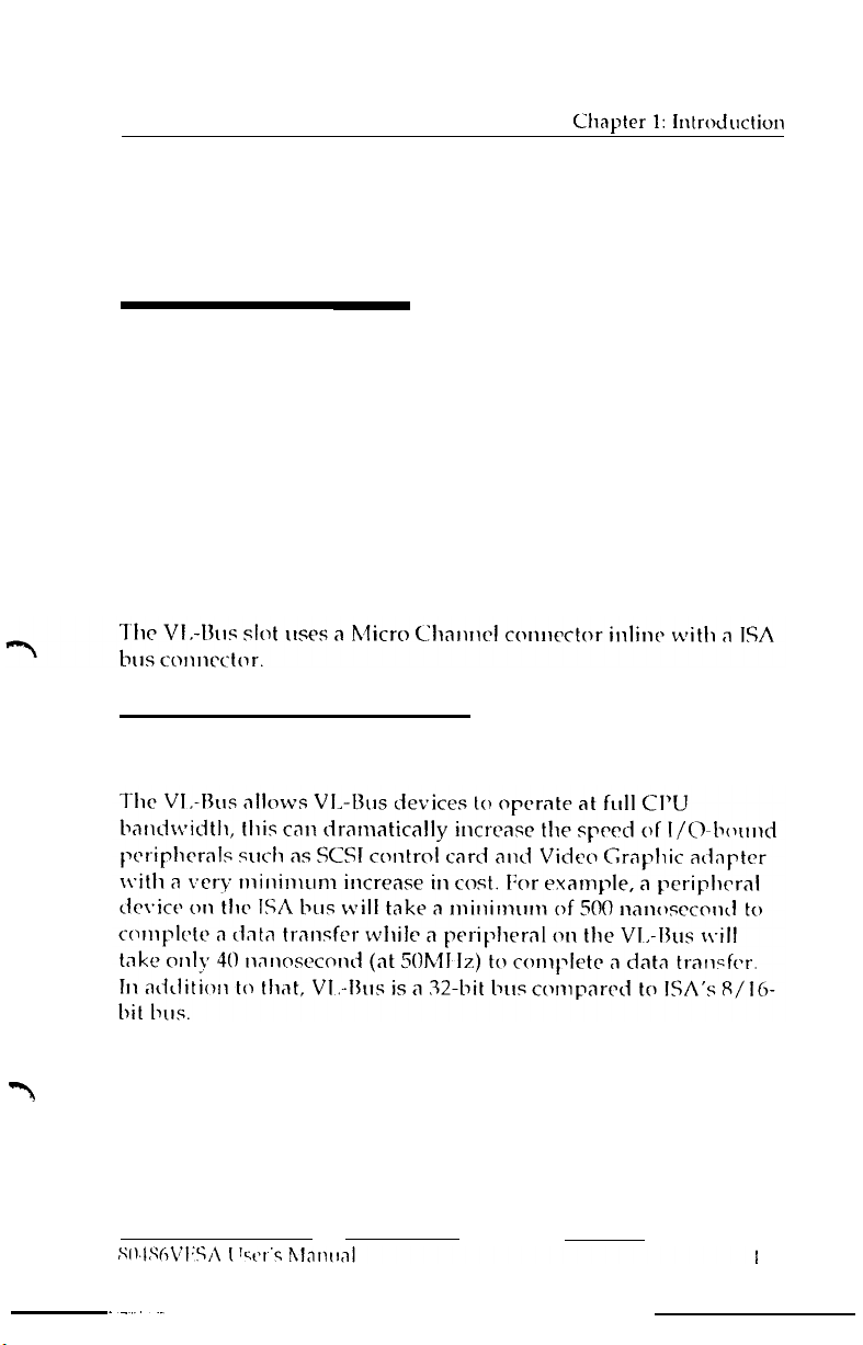
What is VESA VL-Bus?
The VESA
Standard Association committee. The
generally follows the 486 CPU local bus. Additional hardware
functions
intrractinn
capabilities of the
100Mb/sec (at 50
compatibility with
VL-Bus is a proposal from
are added to accommodate VL-Bus master devices
with
the system I/O bus. The
16-bit
ISA bus to
MHz data transfer rate, while maintaining
ISA
add-on
boards.
the
Video
architecture
VL-bus
32-bus
architecture and up to
Electronics
of the
extends
VL-Bus
the
Advantage of VESA VL-Bus
and
Page 5

Chapter 1: Introduction
80486VESA Motherboard Overview
The 80486VESA system board is a high performance, function
enchanced computer system board that combines the power of
Intel’s new 80486 CPU and the VESA VL-bus. The
includes a variety of high-powered features. Its high performance
capability can provide an ideal system board solution for a wide
range of demanding applications like CAD/CAM/CAE, database
management, image processing, artificial intelligence, desktop
publishing, and the environments of network and multiuser
systems. The 80486VESA system board fully utilizes the 32-bit
CPU power.
The 80486VESA system board also incorporates an Intel 80486
microprocessor which has an 8 KByte static RAM cache.
is a four-way set associative cache controller implemented on the
80486 chip
and
an internal enhanced numeric coprocessor unit.
The system also has an option to accommodate
256KB of external cache.
board
design
Included
64KB, 128KB,
and
Because of its unique memory subsystem design, the 80486VESA
allows for 1 Megabyte to 32 Megabytes of 32-bit high speed
memory by using
80486VESA
User’s Manual
256KB, 1MB,
and/or 4MB SIMM
modules.
3
Page 6

Chapter
1:
Introduction
80486VESA Features
l Intel 80486 microprocessor
-
8
KBytes static
-
Internal enhanced numeric coprocessor unit (486DX, 486DX2,
487SX,
l Optional 64/128/256KBytes external cache
l SIMM module memory on system board expandable from 1
Megabyte to 32 Megabytes
l Dual system speed via hardware or software selection
l System and video BIOS relocateable to RAM area for enhanced
performance
l Two 32-bit VL-Bus, two
slots
l Fast A20 implementation to speed-up multitasking operating
system
l Hidden DRAM refresh to boost system performance
l SiS-460 Single Chip
RAM with four-way set associative internal cache
486SX2)
8-bit
ISA bus and four 16-bit ISA
bus
Performance Report
80486VESA-20 MHz:
l Landmark Speed Rating
l Power Meter MIPS
80486VESA-25 MHz:
l Landmark Speed Rating
l Power Meter MIPS
80486VESA-33 MI-Iz:
l Landmark Speed Rating
l Power Meter MIPS
80486VESA-50 MHz:
l Landmark Speed Rating
l Power Meter MIPS
4
: 91.2 MHz (Ver. 1.14)
: 8.898 MIPS (Ver. 1.3)
: 114.1
:
11.136 MIPS (Ver. 1.3)
: 151.9
:
14.819 MIPS (Ver. 1.3)
: 200 +
MHz
MHz
MHz
: 22.271 MIPS (Ver. 1.3)
80486VESA User’s Manual
(Ver. 1.14)
(Ver. 1.14)
(Ver. 1.14)
Page 7

Chapter 2: Configuration a Layout
2
Configuration and layout
Connector and Jumper Settings
Before installing the 80486VESA system board, make sure the
connectors and jumper settings are set for your configuration.
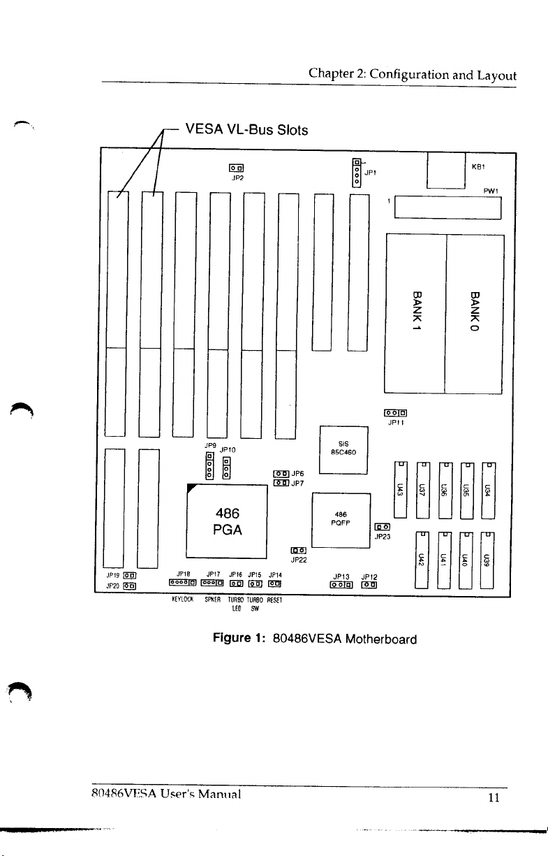
The 80486VESA system board has two jumpers (JP9,
CPU Type selection, and two jumpers (JP12, JP13) for the Cache
Size selection. Connectors are also provided for the front panel
interface between the system board and the computer chassis.
The functions and settings of each connector and jumper setting
are explained as follows (see Figure 1, page 11 for locations).
Front Panel Reset Connector
The reset button connector is a 2-pin single in-line BERG strip. It
is used to reboot the system and will allow safe re-initialization of
the system at any time. The connector should always be set in the
OFF position, otherwise the system will continually reset itself.
The pin assignments are:
JP14 Pin#
1
2
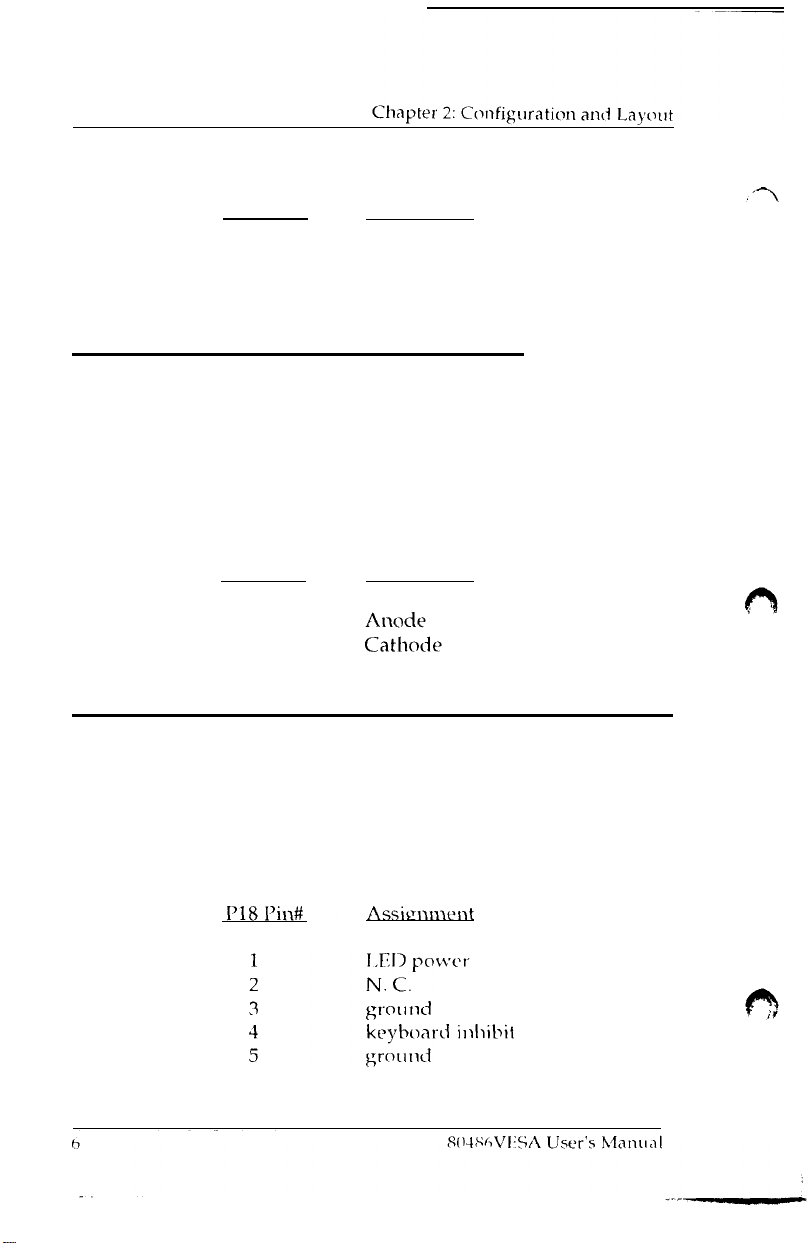
Front Panel Turbo Connector
Connector
connector for the “Turbo” processor speed which can allow you
switch between system speeds. (Please refer to Chapter 3
“Installation
switching procedures). The pin assignments are:
JP15
is a 2-pin single in-line BERG strip. It is the
&
Operation” for a detailed description on speed
(JP14)
Assignment
Ground
Reset Strobe
(JP15)
JP1O)
for the
to
80486VESA
User’s
Manual
5
Page 8
JPl5 Pin#
Assignment
1
2
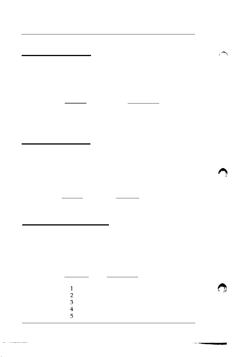
Front Panel Turbo LED Connector
Connector JP16 is a
connected to an LED display indicating the CPU speed.
display lights up when the CPU is running at full speed (Please
refer to Chapter 3 “Installation
about speed change). The pin assignments arc:
2-pin
JP16
Pin#
1
2
single in-line
Front Panel Keylock and Power LED Connector
Connector
for the front panel keylock and power LED connection
connected to a lock on your system
the keyboard by switching
JP18
is a 5-pin single in-line
Ground
Turbo Control
&
Operation”
Assignment
the key.
The pin
(JP16)
BERG
strip. It
for more information
BERG
strip which
case you can
assignments are:
can be
The
When
enable or
(JP18)
provides
disable
it
is
Page 9

Chapter 2: Configuration and Layout
Front Panel Speaker Connector (JP17)
Connector
for the front panel speaker connection. The pin assignments are:
Power Supply Connector
There is a power supply connectors on-board. The pin assignments are:
JP17
is a 4-pin single in-line BERG strip which provides
JP17
Pin#
1
2
3
4
PWl
Pin#
1
2
3
4
5
6
7
8
9
10
11
12
Assienment
power good
+5
VDC
+12
VDC
-12 VDC
ground
ground
ground
ground
-5VDC
+5VDC
+5VDC
+5VDC
(PW1)
Assignment
speaker data
N. C.
ground
+5
v
Page 10
Chapter 2: Configuration and
Layout
External Battery
The 80486VESA motherboard provides one
supply connector. The pin assignments are:
Monitor Type
Jumper JP2 is used to set the display type. The motherboard is
designed to work with both monochrome and color display
monitors. The pin assignments are:
(JPl)
external
JP1 Pin#
1
2
3
4
Assignment
Battery Positive
No Connection
Ground
Ground
(JP2)
JP2
Pin#
1&2
(Closed)
l&2
(Open)
Function
Monochrome Monitor
Color Monitor
battery
Keyboard Connector
The keyboard connector is a 5-pin DIN connector. This connector
consist of a 90-degree printed circuit board PCB mounting. The
pin assignments are:
KBl Pin#
8
(KBl)
Assignment
keyboardclock
keyboarddata
spare
ground
+5
v
80486VESA User’s Manual
Page 11
Chapter 2: Configuration and Layout
CPU Type Selection
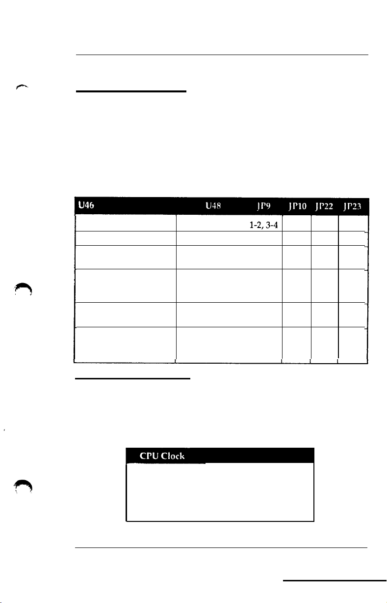
The 80486VESA motherboard can accomodate either the Intel
486DX, 486DX2,486SX, 487SX, 486 Over Drive, 486SX/DX PQFP
or
P24T.
There are two jumpers to be set for the microprocessor
Selection. Configuration of the correct CPU setting will allow
compatibility with various low end and high end applications.
The jumper settings are:
-
486SX
486DX/486DX2
486 Over Drive 168-pin
487SX/487SX2
486 Over Drive 169-pin
P24T
486DX/486DX2 486SX/DX-PQFP l-2,3-4 l-2 Open Close
486 Over Drive 168-pin
487SX/487SX2
486 Over Drive 169-pin
P24T
486SX/DX-PQFP
-
-
-
486SX/DX-PQFP l-2,3-4
1-2,3-4
2-3
l-2,3-4 1-2 Open Close
l-2,3-4 2-3 Open Close
l-2 Close Open
Open Open Close
2-3 Open Close
CPU Clock Selection
The 80486 VESA motherboard uses a CPU frequency generator to
generate the clock instead of oscillator. There are three jumpers to be set
for the CPU clock selection. The jumper settings are:
MHz Open
50
MHz
40
33 MHz Close
25 MHz Open
MI
20
Close
Close
Close
Close
Open
Close
Close
2-3
2-3
l-2
l-2
1-2
80486VESA
User’s Manual
9
Page 12
Cache Memory Configuration
There are two jumpers to be set for the cache memory selection
The jumper selections are as follows:
Note:
64K
128K
256K 2-3
Table 3: Cache Memory Configurations
For 64K
U36, U37, U39,
For 128K
SRAM in locations U34, U35, U36,
For 256K
U35, U36, U37, U39,
cadre,
install 8Kx8 SRAM in locations
U40,
cache,
install 8Kx8
cache install
Open
1-2
U41,
and
U42.
SRAM
32Kx8 SRAM in
U40, U41,
and U42.
in
and
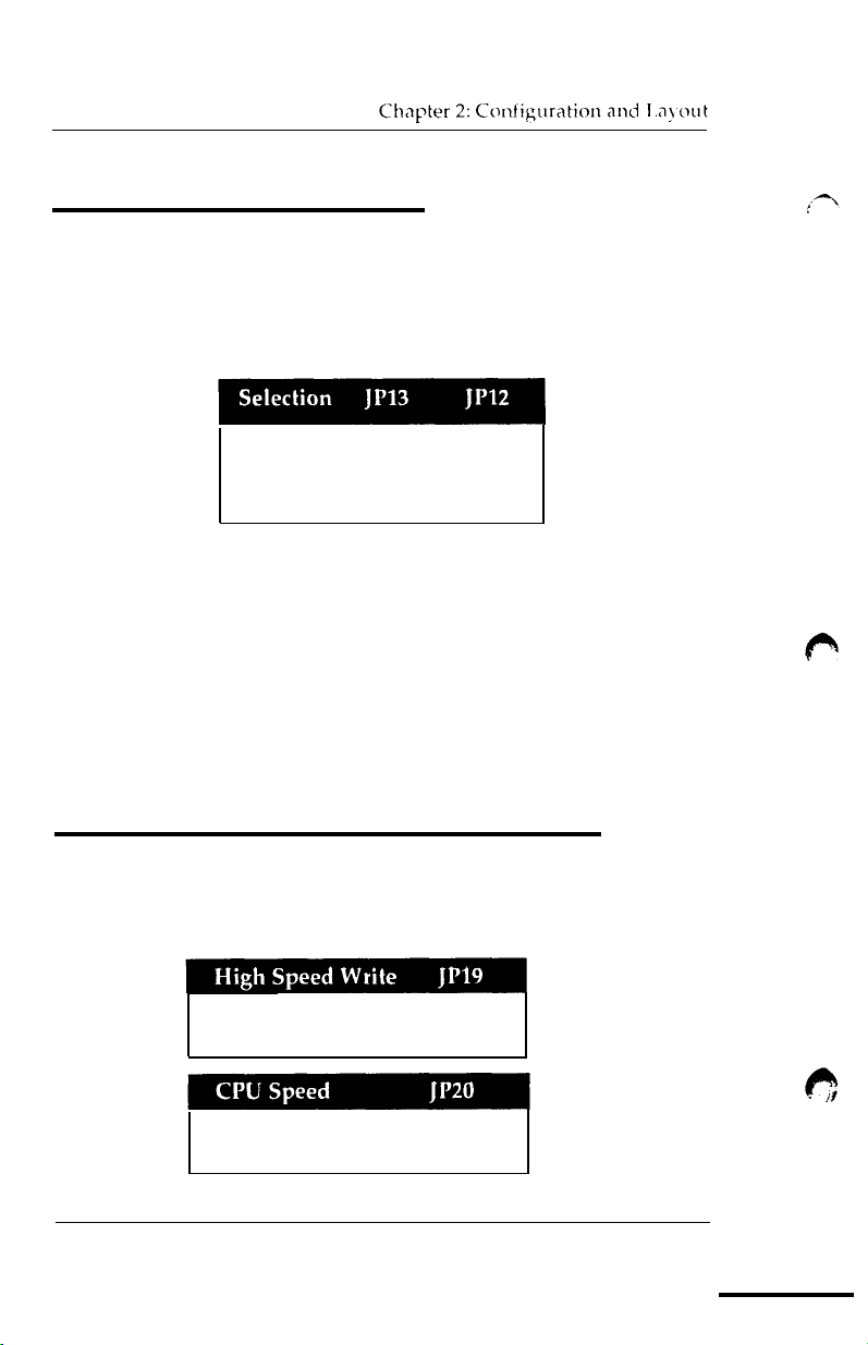
VESA VL-Bus Identifier Jumpers
The identifier jumpers (JP19,
the speed of the host CPU.
0 wait write min.
1 wait write min.
JP20)
allow VL-Bus slave to identify
Open
Close
Open
Close
Close
locations
U37.
locations
(JP19,
1143,
1143,
U43,
JP20)
U34,
1135,
and 32Kx8
U34,
<=33MHz
>
33MHz
10
Open
Close
80486VESA Users Manual
Page 13
Page 14
Chapter 3: Installation and Operation
3
Installation and Operation
Before You Begin
Before removing the motherboard from its anti-static bag, you
need to eliminate any static electricity that may be accumulated on
your body. The charge that can build up in your body may be
more than enough to damage integrated circuits on the system
board. Therefore, it is important to observe basic precautions
whenever you will handle or use computer components.
Although areas with humid climate are much less prone to static
build-up, it is best to always safeguard against accidental damage
that may lead to costly repairs. The following measures
sufficient to protect your equipment from static discharge:
l After removing the system cover, discharge any static
electricity that might have accumulated in your body by
touching a grounded or anti-static surface
pads). If nothing is available, touch the power supply
ing. This assumes the system unit is plugged in
ing
the case. De certain to do this
components from their anti-static
before removing
coverings
(e.g.
anti-static
should
hous
and ground
be
*When handling separate cards, boards or modules, be cau-
tious to avoid contacting with the components on them, and
also with the “gold edge” connectors that plug
sion bus. It is best to handle them either
mounting brackets that attach to the slot opening in the
system cases.
intended to advise reasonable care to
charge problems.
l Make certain that everything that
including the power supply,
stallation work.
I
Iowever, the above recommendations arc just
is
unplugged
by
avoid
connects to
into the expan-
their edges or by
the static dis-
the system case,
before doing the in-
Page 15
Chapter 3: Installation and Operation
Installing The SIMM Modules
The 80486VESA system board can accommodate up to a
maximum of 32 megabytes of memory on board using 8 sockets
for the standard
SIMM modules are available for use with 256KB x
4MB x 9
-
80 nanosecond, fast page mode SIMM memory modules. Each bank contains four SIMM memory sockets. When
installing or removing the SIMM memory modules, extreme care
must be taken to avoid damage to the SIMM sockets. The
80486VESA system board can be configured for various memory
configurations from
the memory configurations available).
To install a SIMM memory module, carefully follow the steps
below:
Step 1 Insert the SIMM module’s “gold edge” connectors into the
socket at a 70-degree angle and guide the component side
of the SIMM module to face the edge of the board. The
module can only fit into the socket one way.
30-pin
SIMM memory modules. Two banks of
1MB
to 32MB. (Refer to Table 4, page 13, for
9, lMB
x 9 or
Step 2Gently press the SIMM module toward the edge of the
board until it snaps into the socket in a vertical position.
The module should clip into the locking tabs at each end
of the socket. If the pegs do not fit into the holes, the
SIMM is probably not inserted fully into the socket.
To remove a SIMM memory module, carefully follow the steps
below:
Step
1 Gently push the edge of the sockets to release the module.
Remove one side of the SIMM module first then the other
side, to prevent from breaking the socket. The module
should fall back at an angle; then it can be removed from
the
socket.
Page 16
Memory Configuration
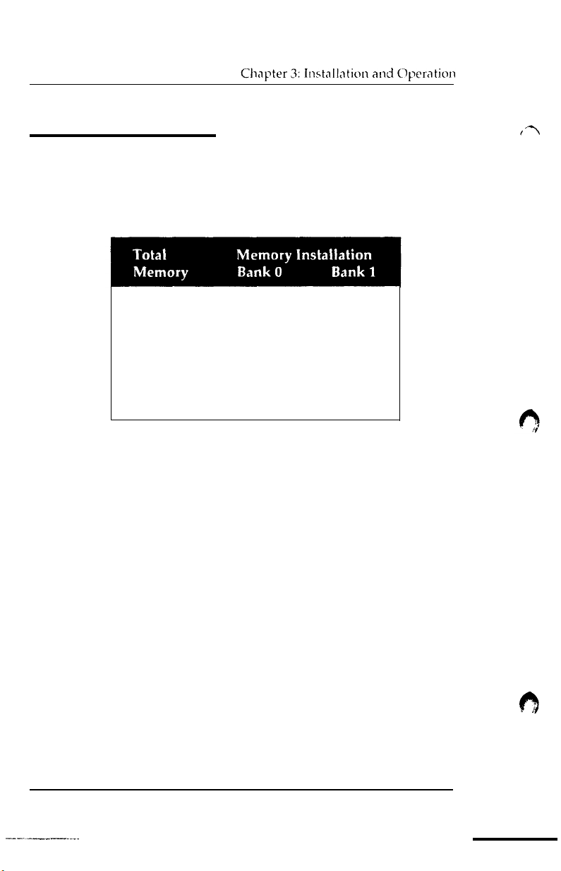
Memory can be installed using
256KB, 1MB
or 4MB SIMM mod-
ules. The following are all the available memory configurations:
1MB 256Kx9
2MB
4MB
8MB
16MB
20MB
32MB
Table
4: Memory Configurations
256Kx9 256Kx9
lMBx9
lMBx9
4MBx9
lMBx9 4MBx9
4MBx9
----
---lMBx9
----
4MBx9
14
80486VESA User’s Manual
Page 17
System Speed Change
The
80486VESA
speeds to accomodate most DOS applications. On power up, the
system will be operating in full speed (factory setting).
You can switch between full and low speeds by toggling the turbo
switch or pressing the keyboard keys.
l Toggling the Turbo Switch
1)
Set the turbo switch to the on position to slow down the
system speed
2)
Set the turbo switch to the off position to speed up the
system speed.
9
Pressing the Keyboard Keys
system board can be configured for full or low
Note: Before
the
turbo switch
1)
2)
using
the keyboard
has
to be set to the off position.
keys
to
control
the system speed,
Press the < CTRL > < ALT > keys while simultaneously
pressing the
Press the
pressing the
< - >
key to slow down the system speed.
<
CTRL > < ALT > keys while simultaneously
<
+ > key to speed up the system speed.
Memory Caching
The
80486VESA
external cache memory. The internal and external cache enable/
disable selections in the BIOS Advanced CMOS Setup program,
will turn ON or OFF, either the
external memory cache.
80486VESA User’s Manual
system board provides an optional 64/128/256KB
80486VESA’s
8K internal cache or
15
Page 18
4
BIOS Setup and Diagnostics
Software Setup
After hardware configuration of the 80486VESA system board is
completed, and system hardware has been assembled, the completed system may be powered-up. At this point, software setup
should be run to ensure that the system information is correct.
The System Setup is sometimes called CMOS Setup or Standard
Setup. Normally, system setup is needed when the system
hardware is not identical with the information contained in the
CMOS RAM, or whenever the CMOS RAM has lost power.
Running AM1 BIOS
When the system is powered on, the BIOS will enter the Power-On
Self Test (POST) routines. These routines are divided into two
phases:
System Test and Initialization (test and initialize system
boards for normal operations)
System Configuration Verification (compare defined
configuration with hardware actually installed)
The
AMI
BIOS performs the various diagnostic checks at the time
the system is powered up; if an error is encountered, the error will
be reported in one of two different ways. If the error occurs before
the display device is initialized, a series of beeps will be
transmitted (See Appendix C).
16
80486 VESA User’s Manual
Page 19
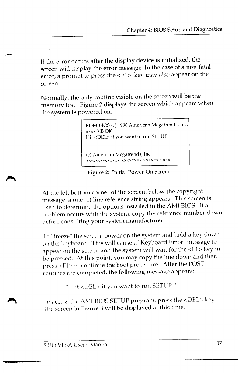
Page 20
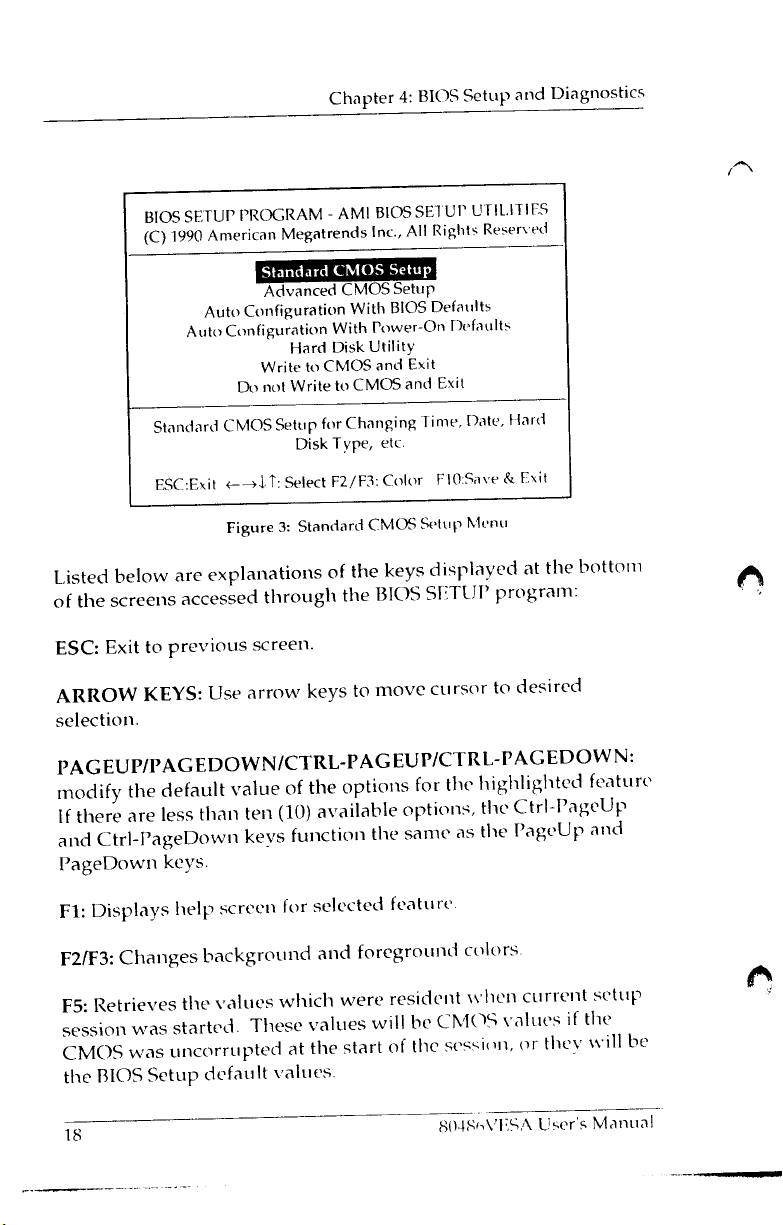
Page 21
Chapter 4: BIOS Setup and Diagnostics
F6: Loads all features in the Advanced CMOS Setup with the BIOS
Setup defaults.
F7:
Loads all features in the Advanced CMOS Setup with the
Power-On defaults.
F10:
Saves all changes made to Setup and exits program
80486VESA User's
--
Manual
19
Page 22
Standard CMOS Setup
Standard CMOS Setup is the first option on the main setup menu
Press <ENTER> at the highlighted selection to access this option.
The screen in Figure 4 will appear.
BIOS Setup Program -Standard
(C) 1991 American
Date
(mm/date/year):
Time
(hour/min/sec): 09:39:06
Daylight Saving: Disabled
Hard disk
Hard
Floppy drive A:
Floppy drive B:
Primary display
Keyboard
Month: Jan,Feb ,......... Dec
Date: 01,02,03 . . 31
Year:
C:type:47
disk
D:type :Not
1901,1902.....2099
Esc = Exit,
Tue
= USER TYPE
Installed
:1.2MB,5.1/4”
:Not
Installed
:Monochrome
:Installed
t+d,?
Megatrends
Jan
01
= Select,
1991
F2/F3:
CMOS SET
Inc., All
Cyln
642
8 0
Color,
Rights Reserved
Base memory:
Ext. memory: OKB
Head
WPCom LZone Sect
PgUp/PgDn =
UP
640KB
0
Modify
I
Figure 4: The Standard CMOS Setup Screen
The standard CMOS Setup utility is used to configure the
following features:
17
Size
43MB
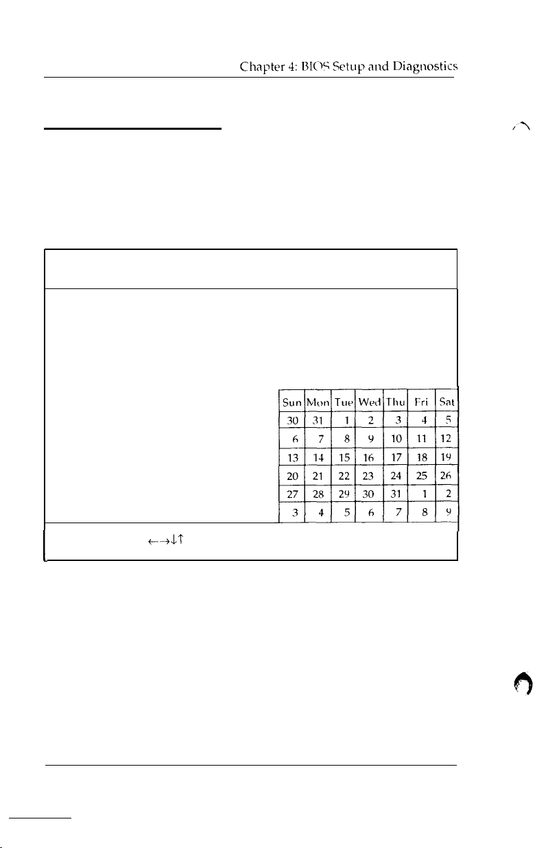
l Set Date: Month, Date, Year. Ranges for each value
are listed below in prompt box in the lower left corner of
the CMOS Setup Screen.
20
__
80486VESA User’s Manual
Page 23
Chapter 4: BIOS Setup and Diagnostics
Set Time: Hour, Minute, and Second. Uses 24 hour clock
format (for PM numbers add 12 to the hour; you would enter
4:30 p.m
as
16:30:00).
Daylight Savings: Disabled or Enabled.
Hard Disk C: and Hard Disk D: Hard disk types from 1 to 46
are standard ones; type 47 is user definable. You must enter
the hard disk parameters for each drive.
Floppy Drive A and Floppy Drive B: The options are 360KB
5 l/4”,
1.2MB
5 l/4”, 720KB 3 l/2”,
1.44MB
3 l/2”, and Not
Installed. Not Installed could be used as an option for
diskless workstations.
Primary Display: Options are Monochrome, Color 40x25,
VGA/PGA/EGA. Color 80x25, and Not Installed. The Not
Installed option could be used for network file servers.
Keyboard: Options are Installed or Not Installed.
“Not Installed” is available for use as an option. This option could
be used for diskless workstations and SCSI hard disks. Type 47
may be used for both disks C: and D:. The parameters for type 47
under Hard Disk C: and Hard Disk D: may be different, which
effectively allows 2 different user definable hard disk types.
80486VESA User’s Manual
---
21
Page 24
l Type: This is the number designation for a
identification parameters.
drive
with certain
l Cyl: This is number of cylinders found in
the specified
drive
ty pe
l Heads: This is the number of heads found in
the
specified
drive type.
l WPcom: WPcom is the read delay circuitry which
takes
into
account the timing differences between the inner and outer
edges of the surface of the disk platter. The number
designates the starting cylinder of the signal.
l L-Zone: LZone is the landing zones of
the
heads. This
number determines the cylinder location where the heads will
normally park when the system is shut down.
l Capacity: This is the formatted capacity of the drive based on
the following formula:
(# of heads) x (# of cylinders) x (# of sectors) x (512 bytes/sec)
22
80486VESA
User’s Manual
Page 25
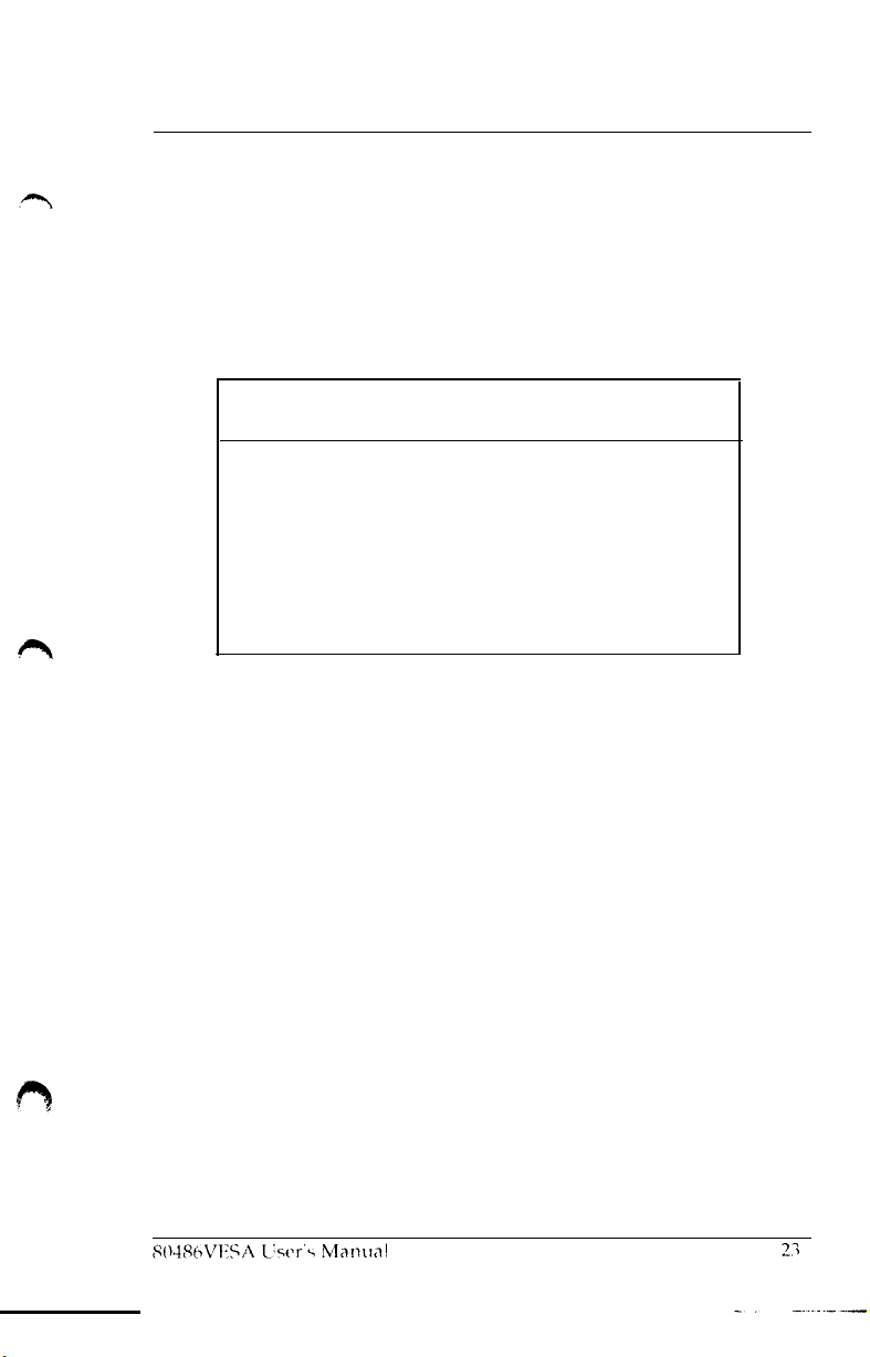
Chapter 4: BIOS Setup and Diagnostics
The following warning message, shown in Figure 5, is displayed
each time when either the Standard CMOS Setup or Advanced
CMOS Setup is selected, before any changes are allowed to any of
the setup parameters.
Improper Use of Setup may Cause
System
If
Hangs,
(ii) Load BIOS Setup Defaults
(iii) Load Power-On Defaults
H
lit <ESC> to Stop now, Any other Key to Continue
. . . . . .
..Enter
Setup by pressing the <DEL> key
Do any of the following After Entering Setup
(i) Alter Options to make System Work
Figure 5: BIOS Setup Warning
Problems
message
!!
Page 26
Advanced CMOS Setup
Chapter 4: BIOS
Setup
and Diagnostics
The Advanced CMOS Setup contains the setup of
features and the
SiS-460
chipset’s configuration registers, to
the
system
help
you achieve an optimum operational environment.
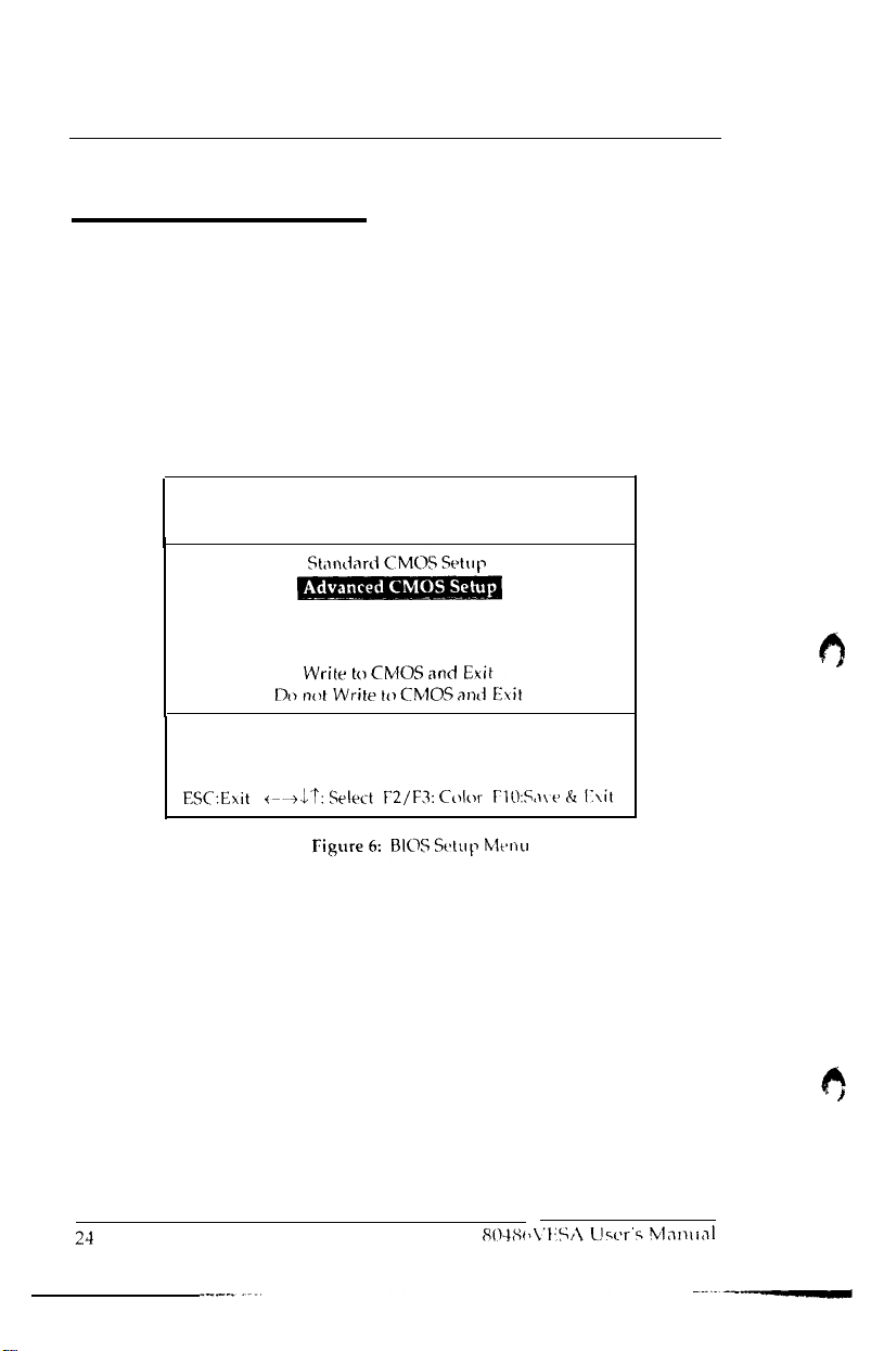
From the following menu, highlight the Advanced CMOS Setup
option and press <ENTER>:
BIOS SETUP
(C) 1990 American
Auto, Configuration With
Standard
PROGRAM AMI
Megatrends
Auto Configuration With BIOS
Hard Disk
CMOS
Setup for Changing
Disk Type, etc.
BIOS
Inc., All
Power-On Defaults
Utility
SETUP UTILI T
Rights Reserved
Defaults
Time,
Date,
IES
Hard
Page 27
Chapter 4: BIOS Setup and Diagnostics
Advanced CMOS Features
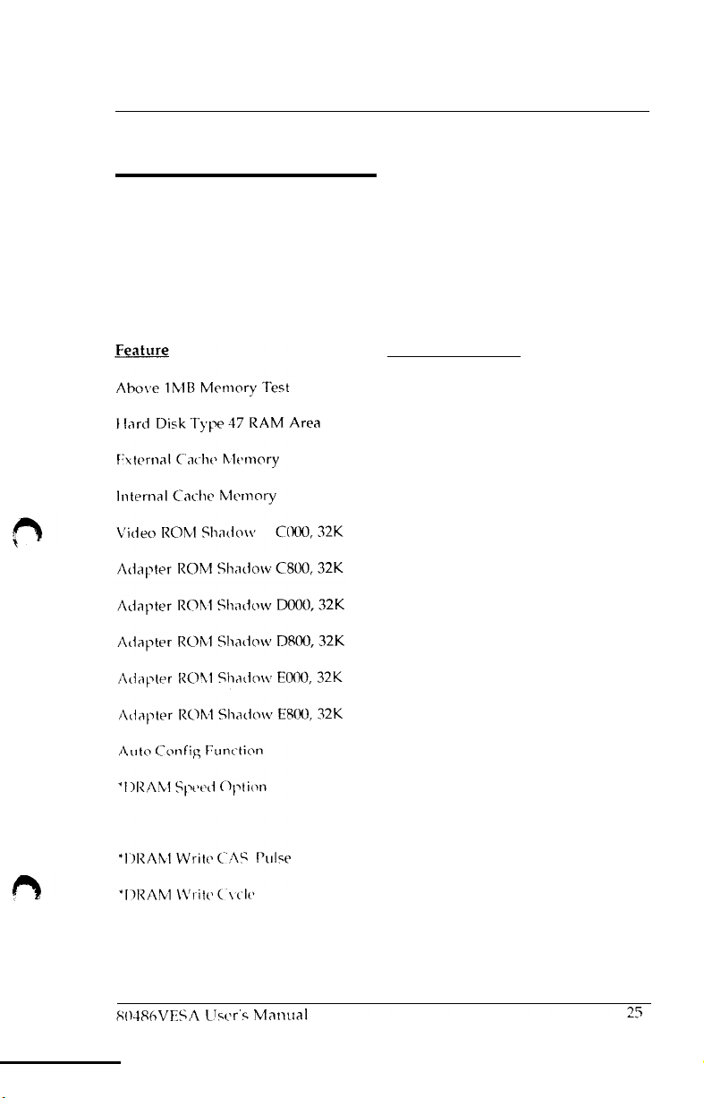
The Advanced CMOS Setup program has several help screens,
accessed by the
for a particular feature and special help for some of the options. The
following table lists the features and toptions available for each.
<Fl>
key, which will display the options available
Available
Options
Disabled (default)
Enabled
0300 (default)
DOS 1 KB
Enabled (default)
Disabled
W/S
(default)
MH z
(40
M
Hz
MHz
MHz)
(25/20
MI z
(50/40/33 MH
Enabled
Disabled
Enabled (default)
Disabled
Disabled (default)
Enabled
Disabled (default)
Enabled
Disabled (default)
Enabled
Disabled (default)
Enabled
Disabled (default)
Enabled
Enabled (default)
Disabled
Slowest (50
Slower
Faster (33 MH z
Fastest (25/2O
lT(25/20
2T (50/40/33 MH z
0 w/s
1
z
Page 28
‘Cache Write
‘Cache Read
‘Bus Clock
Video Cacheable Option:
Bios
Cacheable
Slow CPU
Cycle Option
Cycle Option
Frequency, Select
Option
Below
[25MHz]
2T(25/20 MHz)
3T(50/10/33
1T(25/20 MHz,
256KB
2T(50/40
Cache)
7.15 Ml
I /4 CLK (33 MH
1/5
1/6
Enabled (default)
Disabled
Enabled
Disabled
Disabled (25/33/40/50
Enabled
Note:
Features marked with * are set by BIOS
Config Function” is enabled.
MHz
Cache)
MHZ, 33
z
z
CLK
(20/40
CLK (25/50
(default)
(20
MH z)
automatically
33
MHz w/64KB or
MHz
w/128KB
MH
z
MHz)
MHz)
if “Auto
When Auto Config Function is enabled, the
detect CPU type, CPU frequency
up the optimal parameters to help your system achieve an optimum
and
and reliable operation environment. To set the parameter
to meet your requirement, the Auto
Config
BIOS
will automatically
number of cache banks to set
you
want
Function has to be
disabled.
“Hard Disk Type 47 RAM Area”
-
If the BIOS Shadow RAM is
disabled, the Hard Disk Type 47 parameter table will use regular
RAM. There are two options,
1KB (the top 1KB of the
“Adapter ROM Shadow”
you have expansion cards with ROMs on them, you will need to
0:300
(lower system RAM) and DOS
640K
base memory).
is for shadowing other adapter ROMs. If
know
the ROM addresses.
After
you have made your selection within the advanced CMOS Setup.
press <ESC> to return to the main menu.
26
80486VESA User’s Manual
Page 29
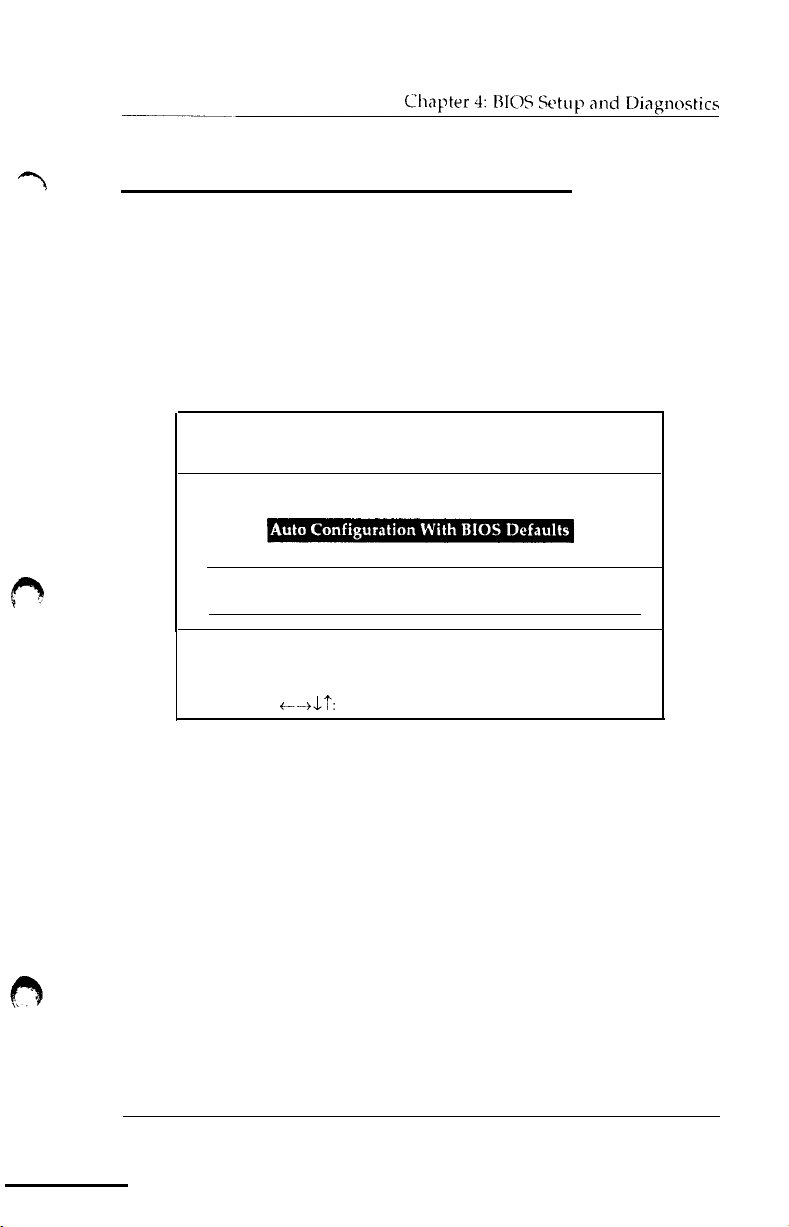
Auto Configuration with BIOS Defaults
The “Auto Configuration with BIOS Defaults” loads the default
system
values
directly from ROM.
From the following
menu
and press <ENTER>
BIOS
setup
(C)
1990 American Megatrends
Auto Configuration With rower-011
Load
BIOS Setup Defaults Values from ROM
Load
BIOS
Setup
ESC:Exit t-+L?:
Figure 8: Auto Configuration
menu
highlight the feature from the main
PROGRAM
Standard CMOS Setup
Advanced CMOS
Default Values for Advanced CMOS and
Select
AMI
Inc., All
F2/F9:
w/
BIOS SE7 UP
Setup
Color
BIOS Defaults Menu
UTILITIES
Rights Reserved
Defaults
Table
F10:Save &
(Y/N)?
Chipset
Exit
80486VESA User’s Manual
__
27
Page 30
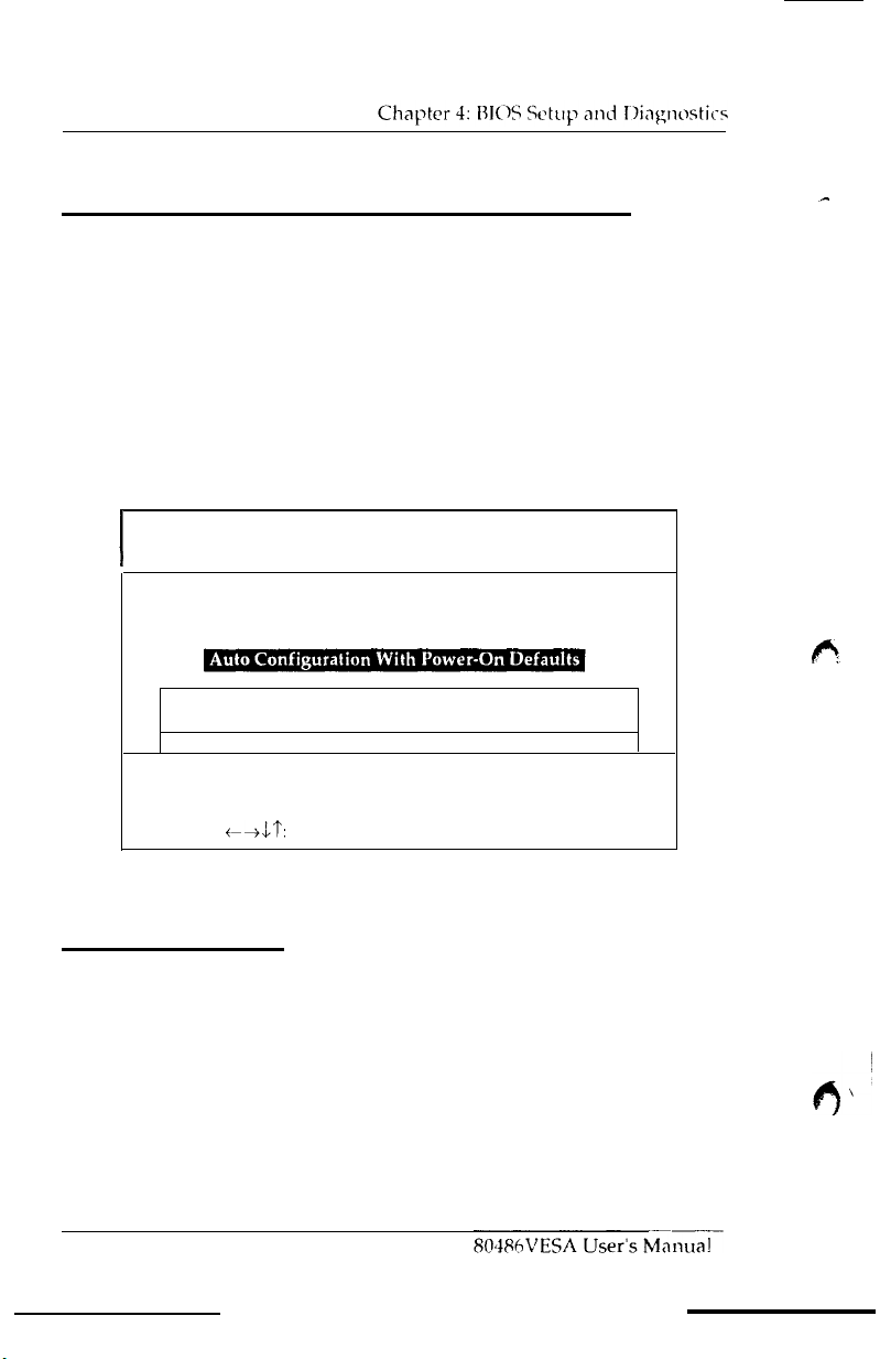
Auto Configuration with Power-On Defaults
The “Auto Configuration with Power-On Defaults” loads
the
settings detected when you turn on the computer. If your svstem
behaves erractically, you can use this feature to check for
incorrect
settings.
From the following menu, highlight the feature from
the
main
menu and press <ENTER>.
BIOS
SETUP
I
Load Power-On Default Values for Advanced CMOS and Chipset
(C)
Load Power-011 Default Values from ROM
ESC:Exit
Figure 9: Auto Configuration
PROGRAM
1990 American
Standard CMOS Setup
Auto Configuration With BIOS Defaults
c++lt:
Advanced CMOS Setup
Select
AMI
BIOS SETUP
Megatrends Inc.,
F2/F9:
Color
F10:Save &
w/ Power-On
UTILITIES
All Rights Reserved
Table
(Y/N)?
Exit
Defaults
Hard Disk Utility
The “Hard Disk Utility” is basic drive setup software. All of the
options are destructive to data existing on a disk drive. The
options are used for low-level formatting before using the DOS
“FDISK”
28
and “FORMAT”, or similiar utilities.
Page 31

Chapter 4: BIOS Setup and Diagnostics
Write to CMOS and Exit/Do not Exit
After completion of all selections, move the cursor down to either
“Write to CMOS and Exit” or “Do not Write to CMOS and Exit” to
save the data/values changed, or to abandon all the changes and
continue with the booting process.
From the following menu, highlight the option and press
<ENTER>.
BIOS SETUP PROGRAM - AMI BIOS SETUP UTILITIES
(C) 1990 American Megatrends Inc., All Rights Reserved
Standard CMOS Setup
Auto Configuration With BIOS Defaults
Auto
Advanced CMOS Setup
Configuration With Power-On Defaults
I
ESC:Exit td7‘:
10:
Figure
Write to CMOS and Exit (Y/N)?
Select F2/F9: Color F10:Save & Exit
Write to CMOS/Do not Write to CMOS
Menu
Page 32
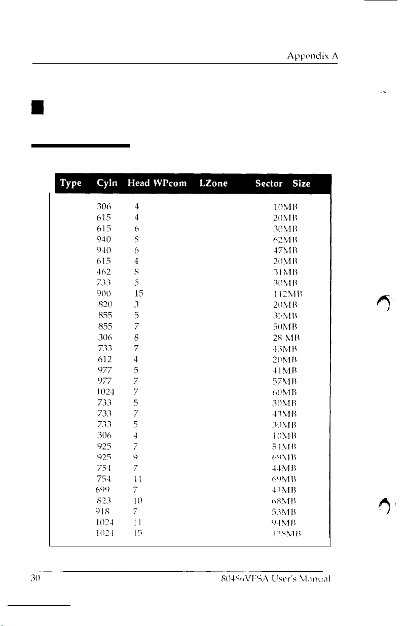
4
Appendix A
Disk Drive Types
1
2
3
4
5
6
7
8
9
10
11
12
13
14
16
17
18
19
20
21
22
23
24
25
26
27
28
29
30
31
32
125
300 615
300
512
512 940
65535 6 15
256
65535 733
65535
65535 828
65535
65535 855
128
65535
0
300 977
65535
512
300 732
300
300 733
0
0
65535
754
65535
256
65535
918
6 5 5
3
65535
305
6
1 5
940
511
981
855
319
733
663
977
1024
732
336
925
925
754
754
699
823
918
5
1024
1024
I7
17
17
17
17
17
17
I7
17
I7
17
17
17
17
17
17
I7
17
17
17
I7
I7
I7
17
17
17
17
I7
17
17
I7
Page 33
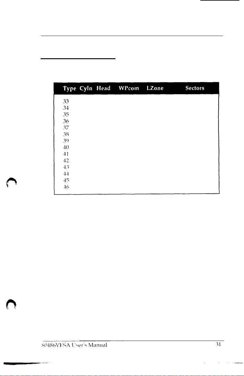
Disk Drive Types (Cont.)
Appendix A
1024
612
1024
1024
615
987
987
820
977
981
830
830
9
I 7
1224
5
2
9
8
8
3
7
6
5
5
7
IO
15
15
1024
128
65535
512
128
987
987
820
977
981
512
65535
65535
65535
1024
612
1024
1024
615
987
987
820
977
981
830
830
918
1223
17
17
17
17
17
17
17
17
17
17
17
17
17
17
43MB
10MB
77MB
68MR
41MB
25MB
57MB
41MB
41MB
41MB
48M
II
69MB
114MB
152MB
Page 34
I
Appendix
B
Specifications
Memory:
Up to 32MB of 32 bit RAM
Expansion Slots:
Two 32-bit VL-Bus, two S-bit ISA bus and four
slots.
Keyboard Support:
Enhanced AT keyboard
Size:
8.6 inches by 10 inches
Processor:
/
Intel 80486DX 33/50 MHz
Intel 80486SX
Intel 80486 Over Drive
20/25
MHz / Intel 80487SX
Intel 80486DX2
/ P24T /
486SX-PQFP / 486DX-PQFP
50/66
20/25
16-bit
MHz
MHz
Appendix
ISA bus
B
Co-Processor:
Internal enhanced numeric coprocessor
486 Over Drive,
Cache Controller:
Internal 8K byte of cache memory (Four-way set associative)
Support for 64/128/256Kbyte external cache memory
(Direct mapped, Write-back)
BIOS:
AMI (American Megatrends, Inc.)
Environment:
Operating Temperature: 10 degrees C to 40 degrees C.
Required Airflow: 50 linear feet per min. across 80486
Humidity: 0 to 90% noncondensing
Altitude: 0 to 10,000 feet above sea level
32
P24T)
(486DX,
80486VESA User’s Manual
486DX2,487SX,
Page 35
System Requirements
Power Supplies for 486 Computers
A clean steady power source is necessary to get reliable performance from the system. With the high clock speeds of the CPU
(running at
becomes
meet the standards required by the CPU, however some have been found
to be out of specification.
by your system, be sure your power supply provicies a voltage
range of 5.25 volts maximum to 4.95 volts minimum.
20MH z
even
or above) the quality of the power
more important. Most
To be certain of the highest performance
power
supplies on the market
supply
In areas
line noise filter between the power and the computer.
with
noisy power transmission, we suggest the use of a
80486VESA User’s Manual 33
Page 36
H
Appendix C
Troubleshooting
The POST (power-on self test) performs
the time the system is powered ON. Whenever an error is
countered during these tests, either you hear a
see an error displayed on the screen.
Non-fatal errors are those which, in most cases,
to continue the boot
appear
Fatal
the boot up procedure. If
with
These fatal errors are usually communicated through a series
audible beeps. The numbers on
correspond to the number of beeps for the corresponding error.
The following error messages are conveyed through a number of
short beeps; you can always identify the error by counting the
number of short beeps.
on
the screen.
errors are those which will not allow
your system manufacturer for possible repairs.
#
OF BEEPS
up
process. The error messages normallv
a
fatal error occurs,
the
MEANING OF ERROR
Refresh Failure
refresh circuitry of
is faulty.
Parity Error - A parity error was
detected in the base mrmnry (the
first block of 64
various
fatal error list below
-
KB)
diagnostic
few
short
allow
the system
the
svstcm to continue
you
should consult
The memory
the
motherboard
of the system.
tests at
en-
beeps
or
of
34
80486VESA
User’s Manual
Page 37
Appendix C
Base 64KB Memory Failure - A memory
failure occurred within the first 64 KB of memory.
Timer Not Operational
-
Timer #l on the
motherboard has failed to function properly.
Processor Error
-
The CPU on the motherboard
has generated an error.
-
8042-Gate A20 Failure
The keyboard controller
(8042) contains the Gate A20 switch which allows
the CPU to operate in virtual mode. This error
message means that the BIOS is not ahle to switch
the
CPU into protected mode.
Processor Exception Interrupt Error
on
the motherboard has generated an exception
-
The CPU
interrupt.
Display Memory Read/Write Error - The system
video adapter is either missing or its memory is
faulty.
ROM Checksum Error -
value
CMOS Shutdown Register Read/Write Error
The
Note: This
is
not
a fatal error.
The
ROM checksum
does not match the value encoded in the BIOS.
-
shutdown register for the CMOS memory has
failed.
Page 38
Appendix C
Non-Fatal BIOS Error Messages
If a non-fatal error occurs during the POST routines performed
each time the system is powered on, the error message
on the screen in the following format:
will appear
ERROR Message
Line
1
ERROR Message Line 2
press
<Fl>
to RESUME
Write down the error message and press the <Fl> key to continue
with the boot-up procedure.
For
most of the error messages, you will not
Message Line 2.”
“ERROR Message Line
UTILITY”. Pressing the
Generally,
2”,
the message will be “RUN SETUP
<Fl>
for those messages containing an
key will invoke
Program. The following are descriptions of
l 8042 Gate A20 Error
-
The gate-A20 portion of the keyboard
controller (8042) has failed to operate correctly. The
see
an
"ERROR
the BIOS Setup
the
error
messages.
8042
chip
should be replaced.
l Address Line Short
-
An error has occurred in the address
decoding circuitry of the motherboard
l Cache Memory Bad, Do Not Enable Cache
found the cache memory of the motherboard to be
Consult your system manufacturer to
l CH-2 Timer Error
two timers. An error with tinier #l is a fatal
on page 34.
message
If an error occurs with tinier
appears.
-
Most AT standard
repair
! -
The BIOS
has
defective.
the problem.
motherboards include
error, explained
#2,
this
error
Page 39
Appendix C
l C: Drive Error
-
The BIOS is not receiving any response from
hard disk C:. It may be necessary to run the Hard Disk Utility
to correct this problem. Also, check the type of hard disk
selected in the Standard CMOS Setup of the BIOS Setup
Program to see if the correct hard disk drive has been selected.
l C: Drive Failure
-
The BIOS can not get any response
from the hard disk drive C:. It may be necessary to replace the
hard disk.
l CMOS Battery State Low
-
There is a battery in your system
which is used for storing the CMOS values. This battery
appears to be low in power and needs to be replaced.
l CMOS Checksum Failure
-
After the CMOS values are saved,
a checksum value is generated to provide for error checking. If
the previous value is different from the value currently read,
this error message appears. To correct this error, you should
run
BIOS
Setup Program.
l CMOS Display Type Mismatch - The type of
video
stored in
CMOS does not match the type detected by the BIOS. Run the
BIOS Setup Program to correct this error.
l CMOS Memory Size Mismatch
amount of memory on your motherboard to be different
-
If the BIOS finds the
from
the amount stored in CMOS, this error message is generated.
Run the
BIOS
Setup Program to correct this error.
. CMOS System Options Not Set
-
The values stored in the
CMOS arc either corrupt or nonexistent. Run
Program
l CMOS Time
Setup
to
correct this error.
&
Date Not Set - Run the
of
the
BIOS SETUP
Standard
Program to set the
the CMOS
the
BIOS Setup
CMOS
date
and
time of
Page 40
D:
Drive Error - The BIOS is not receiving any response from
hard disk D:. It may be necessary to run the I
to
correct this problem. Also, check the type of hard disk
Hard
Disk Utility
selected in the Standard CMOS Setup of the BIOS Setup
Program to see if the correct hard disk
drive
has been selected.
D: Drive Failure
-
The BIOS can not get
any
response
from the hard disk drive D:. It may be necessary to replace the
hard disk.
Diskette Boot Failure
-
The diskette used to boot-up in
floppy
drive A: is corrupt, which means you can not use it to boot-up
the system. Use another boot diskette and follow the
instructions on the screen.
Display Switch Not Proper
-
Some systems require that a
video switch on the motherboard be set to either color or
monochrome, depending upon the type of video you are
using. To correct this situation, set the switch properly.
(Remember
to
shut down the system first).
DMA #1 Error - An error has occurred with the first DMA
channel on the motherboard.
DMA
#2
Error - An error has occurred with the second
DMA channel on the motherboard.
DMA Error
-
An error has occurred with the DMA controller
on the motherboard.
FDD Controller Failure
-
The BIOS is not able to
comnuni-
cate with the floppy disk drive controller. Check all appropriate connections after the system is powered off.
HDD Controller Failure
-
The BIOS is not able to communicate with the hard disk drive controller.
connections after the system is powered off.
38
80586VESA User’s Manual
Check
all appropriate
Page 41
Appendix C
l C: Drive Failure
-
The BIOS can not get any response
from the hard disk drive C:. It may be necessary to replace the
hard disk.
l D: Drive Failure
-
The BIOS can not get any response
from the hard disk drive D:. It may be necessary to replace the
hard disk.
l CMOS Time
&
Date Not Set - Run the Standard CMOS
Setup of the BIOS SETUP Program to set the date and time of
the CMOS.
l Cache Memory Bad, Do Not Enable Cache
! -
The BIOS has
found the cache memory of the motherboard to be defective.
Consult your system manufacturer to repair the problem.
l INTR #l Error
-
The interrupt channel #l has failed the
POST routine.
l INTR
#2
Error - The interrupt channel #2 has failed the POST
routine.
l Invalid Boot Diskette
-
The BIOS can read the diskette in
floppy drive A:, but it can not boot-up the system with it. Use
another boot diskette and follow the instructions on the
screen.
l KB/Interface Error
-
The BIOS has found an error with the
keyboard connector on the motherboard.
l Keyboard Error
with the keyboard. Make sure you have an
-
The BIOS has encountered a timing problem
AMI
Keyboard
BIOS installed in your system. You may also set the
“Keyboard” option in the Standard CMOS Setup to “Not
Installed”, which will cause the BIOS to skip the keyboard
POST routines.
80486VESA User’s Manual 39
Page 42
l Keyboard is Locked...Unlock It
-
The
keyboard lock on the
system is engaged. The system must be unlocked to continue
the boot up procedure.
l No ROM BASIC
-
This error occurs when a proper bootable
sector cannot be found on either the floppy diskette drive A:
or the hard disk drive C:. The BIOS will trv at this point
to
ROM Basic, and the error message will be generated when
BIOS does not find it.
l Off Board Parity Error
-
The BIOS has encountered a parity
error with some memory installed in an I/O bus expansion
slot. The message will appear as follows:
OFF BOARD PARITY ERROR
ADDR (HEX) = (XXXX)
where XXXX is the address (in hexadecimal) at which
has occurred. “Off Board” means that it is part of the
the error
memory
installed on an expansion card in an I/O bus expansion slot, as
opposed to memory attached directly to the motherboard.
l On Board Parity Error -The
error with some memory installed on
BIOS
has encountered a
the
motherboard.
parity
The
message will appear as follows:
ON BOARD PARITY ERROR
ADDR (I
EX
= (XXXX)
run
the
where XXXX is the address (in hexadecimal) at which
has occurred.
“On
Board” means that it is part of the memory
the error
attached directly to the motherboard, as opposed to memory
installed on an expansion card in an I/O
l Parity Error ????
-
The BIOS has
encountered
error with some memory in the system, but it is not
bus
expansion slot.
a paritv
able
determine the address of the error.
to
Page 43
Appendix
I
Appendix D
Warranty Information
Your 80486VESA system board comes with a limited one-year
warranty. The manufacturer warrants this product against defects
in material and workmanship for one (1) year from date of purchase. Defective parts will be exchanged or repaired at the
manufacturer’s option, for one (1) year after date of original
purchase.
Service can be obtained by calling the manufacturer for a Return
Merchandise Authorization (RMA) number. A receipt or copy of
invoice with date of purchase is also required before any warranty
service will be rendered. Write the RMA number legibly on the
outside of the shipping carton and mail prepaid or hand carry to
the manufacturer. Shipping and handling charges will be applied
for all orders that have to be mailed when service is complete.
D
This warranty covers normal consumer use and does not cover
damages incurred in shipping or failure due to abuse, misuse, or
misapplication, nor as a result of service or modification other
than by the manufacturer.
80486VESA
User’s Manual
41
 Loading...