

Freespirit 800, 831.300290 User Manual

Model No. 831.300290
Serial No.
Serial
Number
Decal
If you are MISSING PARTS or
require INFORMATION on how
to operate this product, call
1-888-936-ICON
(1-888-936-4266).
To schedule REPAIR SERVICE
or to purchase parts,
call SEARS toll-free at:
1-800-4-MY-HOME
(1-800-469-4663)
24 hours a day, 7 days week.
USER’S MANUAL
®
CAUTION
Read all precautions and instructions in this manual before using
this equipment. Keep this manu
al for future reference.
-

TABLE OF CONTENTS
IMPORTANT PRECAUTIONS . . . . . . . . . . . . . . . . . . . . . . . . . . . . . . . . . . . . . . . . . . . . . . . . . . . . . . . . . . . . . . . .3
BEFORE YOU BEGIN . . . . . . . . . . . . . . . . . . . . . . . . . . . . . . . . . . . . . . . . . . . . . . . . . . . . . . . . . . . . . . . . . . . . . .4
ASSEMBLY . . . . . . . . . . . . . . . . . . . . . . . . . . . . . . . . . . . . . . . . . . . . . . . . . . . . . . . . . . . . . . . . . . . . . . . . . . . . . . .5
HOW TO USE THE ELLIPTICAL CROSSTRAINER . . . . . . . . . . . . . . . . . . . . . . . . . . . . . . . . . . . . . . . . . . . . . . .9
MAINTENANCE AND TROUBLESHOOTING . . . . . . . . . . . . . . . . . . . . . . . . . . . . . . . . . . . . . . . . . . . . . . . . . . .19
CONDITIONING GUIDELINES . . . . . . . . . . . . . . . . . . . . . . . . . . . . . . . . . . . . . . . . . . . . . . . . . . . . . . . . . . . . . . .20
PART LIST . . . . . . . . . . . . . . . . . . . . . . . . . . . . . . . . . . . . . . . . . . . . . . . . . . . . . . . . . . . . . . . . . . . . . . . . . . . . . .22
EXPLODED DRAWING . . . . . . . . . . . . . . . . . . . . . . . . . . . . . . . . . . . . . . . . . . . . . . . . . . . . . . . . . . . . . . . . . . . .23
HOW TO ORDER REPLACEMENT PARTS . . . . . . . . . . . . . . . . . . . . . . . . . . . . . . . . . . . . . . . . . . . . .Back Cover
LIMITED WARRANTY . . . . . . . . . . . . . . . . . . . . . . . . . . . . . . . . . . . . . . . . . . . . . . . . . . . . . . . . . . . . . .Back Cover
2
IMPORTANT PRECAUTIONS
WARNING: To reduce the risk of serious injury, read the following important precau-
tions before using the elliptical crosstrainer.
Read all instructions in this manual before
1.
using the elliptical crosstrainer.
2. It is the responsibility of the owner to ensure
that all users of the elliptical crosstrainer
are adequately informed of all precautions.
heart rate readings. The pulse sensor is
intended only as an exercise aid in determining heart rate trends in general.
11. Keep your back straight when using the elliptical crosstrainer; do not arch your back.
3. The elliptical crosstrainer is intended for
home use only. Do not use the elliptical
crosstrainer in a commercial, rental, or institutional setting.
Place the elliptical crosstrainer on a level
4.
surface, with a mat beneath it to protect the
floor or carpet. Keep the elliptical crosstrainer indoors, away from moisture and dust.
5. Inspect and properly tighten all parts regularly. Replace any worn parts immediately.
6. Keep children under 12 and pets away from
the elliptical crosstrainer at all times.
7. The elliptical crosstrainer should not be used
by persons weighing more than 115 kg (250
lbs.).
8. Wear appropriate exercise clothes when using
the elliptical crosstrainer
shoes for foot protection while exercising.
9. Hold the handgrip pulse sensor or the handlebars when mounting, dismounting, or
using the elliptical
. Always wear athletic
crosstrainer
.
12. If you feel pain or dizziness while exercising,
stop immediately and begin cooling down.
13. When you stop exercising, allow the pedals
to slowly come to a stop.
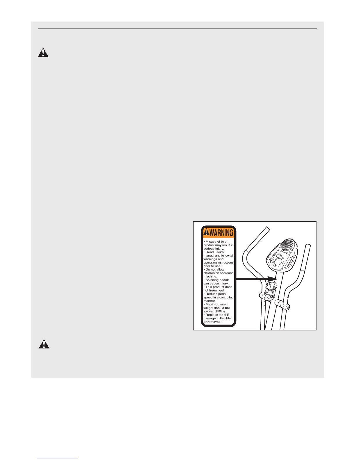
14. The decal shown below has been placed on
the elliptical crosstrainer. If the decal is
missing, or if it is not legible, please call our
manufacture’s Customer Service Department
toll-free at 1-888-936-4266 to order a free
replacement decal. Apply the decal in the
location shown.
10. The pulse sensor is not a medical device.
Various factors may affect the accuracy of
WARNING: Before beginning this or any exercise program, consult your physician.
This is especially important for persons over the age of 35 or persons with pre-existing health problems. Read all instructions before using. SEARS assumes no responsibility for personal injury or
property damage sustained by or through the use of this product.
3
BEFORE YOU BEGIN
Congratulations for selecting the new FreeSpirit®800
CARDIO CROSSTRAINER
incredibly smooth exerciser that moves your feet in a
natural elliptical path, minimizing the impact on your
knees and ankles. And the unique FreeSpirit®800 features adjustable resistance and a state-of-the-art console to help you get the most from your exercise.
Welcome to a whole new world of natural, ellipticalmotion exercise from FreeSpirit.
For your benefit, read this manual carefully before
you use the elliptical crosstrainer. If you have ques-
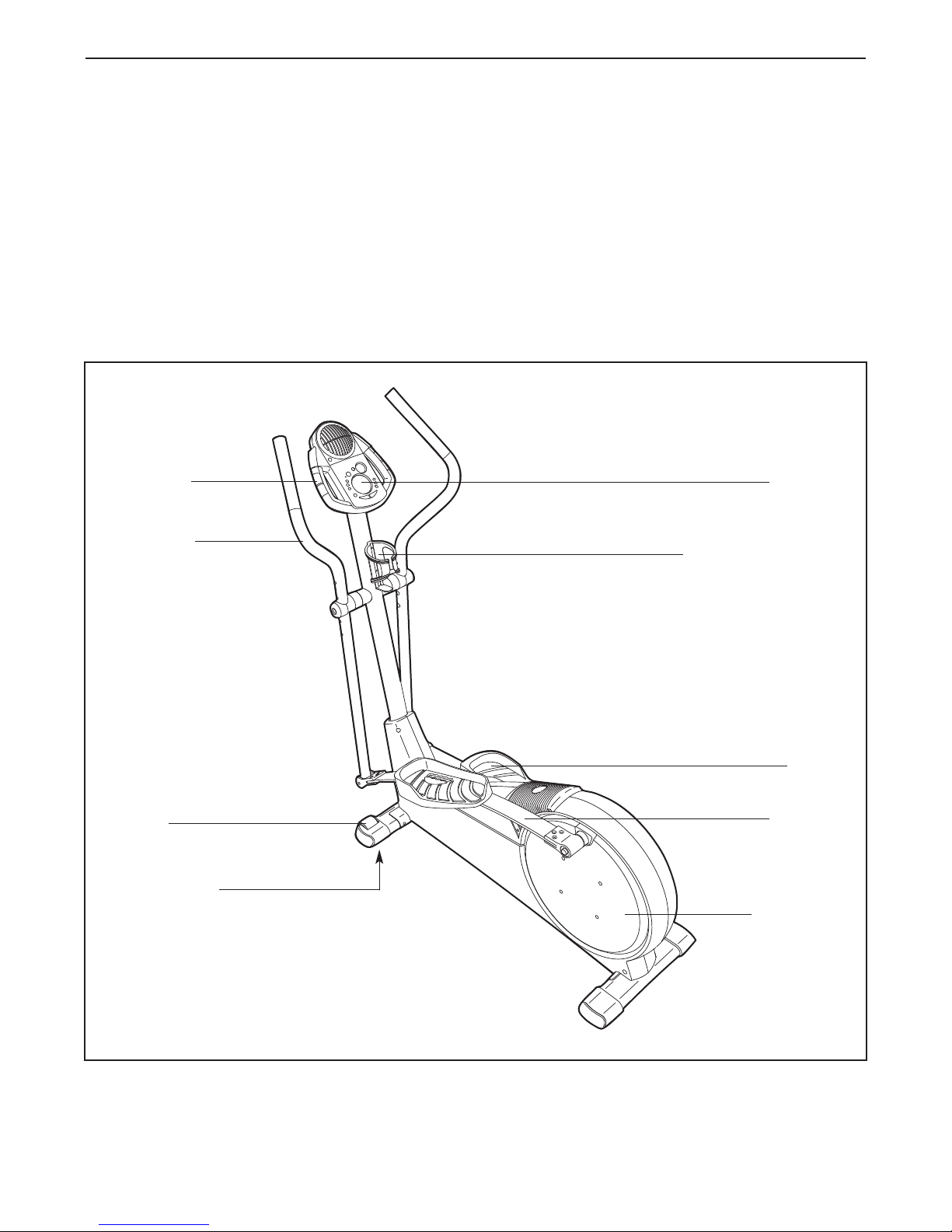
Handgrip
Pulse Sensor
Handlebar
. The FreeSpirit
®
800 is an
tions after reading this manual, please call our manufacture’
1-888-936-4266, Monday through Friday 8h00 until
18h30 eastern time (excluding holidays). To help us
assist you, please note the product model number and
serial number before calling. The model number is
831.300290. The serial number can be found on a
decal attached to the elliptical crosstrainer (see the
front cover of this manual for the location of the decal).
Before reading further, please familiarize yourself with
the parts that are labeled in the drawing below.
s Customer Service Department toll-free at
Console
Water Bottle Holder*
FRONT
Wheel
Leveling Foot
LEFT SIDE
*No water bottle is included
Pedal
Flex Bar
Pedal Disk
BACK
4
ASSEMBLY
M10 x 112mm Carriage Bolt (34)–4
M10 x 88mm Button Screw (63)–1
M10 x 78mm Button Bolt (27)–2
M4 x 16mm
Screw (66)–4
M10 Nylon
Locknut (29)–6
M8 Nylon
Locknut (46)–4
M10 Split
Washer (70)–1
Frame Spacer (83)–1
M8 x 19mm Shoulder
Screw (22)–2
M8 x 45mm Button Bolt (50)–4
M10 x 33mm Carriage
Bolt (20)–2
M4 x 22mm
Screw (93)–2
M10.3 Black
Washer (53)–2
M10
Washer (38)–6
Assembly requires two persons. Place all parts of the elliptical crosstrainer in a cleared area and remove the
packing materials. Do not dispose of the packing materials until assembly is completed. In addition to the
included allen wrenches, assembly requires a phillips screwdriver
wrench , and a rubber mallet .
As you assemble the elliptical crosstrainer, use the drawings below to identify the small parts used in assembly.
The number in parenthesis below each drawing refers to the key number of the part, from the PART LIST on
page 22. The second number refers to the quantity needed for assembly.
been pre-assembled. If a part is not in the parts bag, check to see if it has been pre-assembled.
Note: Some small parts may have
, an adjustable
5
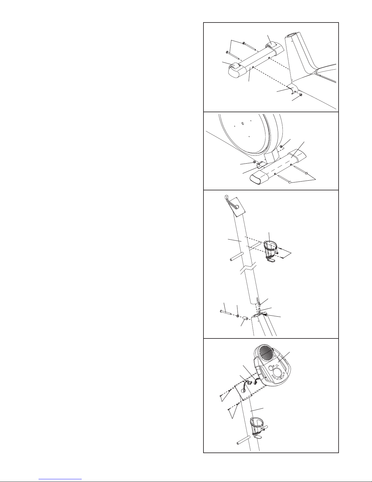
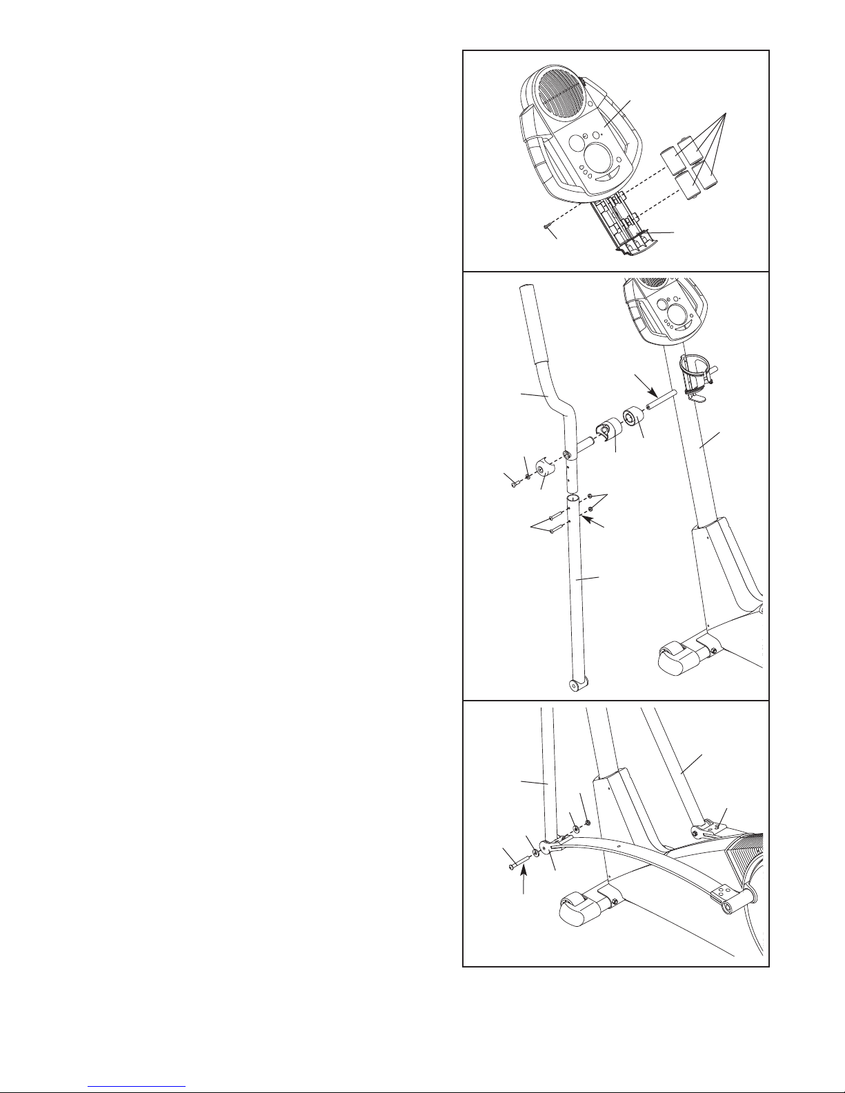
1. Identify the Front Stabilizer (3). While another person
lifts the front of the Frame (1), attach the Front
Stabilizer to the Frame with two M10 x 1
Carriage Bolts (34) and two M10 Nylon Locknuts (29).
Make sure that the Front Stabilizer is turned so the
Wheels (32) are not touching the floor.
12mm
1
34
32
32
3
1
29
2. While another person lifts the back of the Frame (1),
attach the Rear Stabilizer (4) to the Frame with two
M10 x 112mm Carriage Bolts (34) and two M10 Nylon
Locknuts (29).
3. While another person holds the Upright (2) in the position shown, connect the Upper Wire Harness (86) to
the Lower Wire Harness (87). Carefully pull the
upper end of the Upper Wire Harness to remove
any slack. While holding the upper end of the
Upper Wire Harness, insert the Upright into the
Frame (1). Do not pinch the Wire Harnesses.
Slide an M10 Split Washer (70) and a Frame Spacer
(83) onto an M10 x 88mm Button Bolt (63). Insert the
Button Bolt into the Frame (1) and the Upright (2).
Make sure that the concave end of the Frame
Spacer is turned toward the Frame. Do not tighten
the Button Bolt yet.
Attach the W
(2) with two M4 x 22mm Screws (93).
ater Bottle Holder (91) to the Upright
2
29
4
29
1
3
91
2
63
70
Make sure the
wire harnesses
do not get
pinched and
damaged during
this step.
93
86
87
1
34
4. While another person holds the Console (5) in the
position shown, connect the wire harness on the
Console to the Upper Wire Harness (86). Insert the
excess wire harness into the Upright (2). Next, attach
the Console to the Upright with four M4 x 16mm
Screws (66).
harnesses.
Be careful to avoid pinching the wire
83
4
Wire
Harness
86
66
66
2
5
Make sure the
wire harnesses
do not get
pinched and
damaged during
this step.
6
5. The Console (5) requires four “D” batteries (not included); alkaline batteries are recommended. Remove the
indicated screw from the battery drawer
battery drawer open. Insert four batteries into the battery drawer;
ed as shown by the markings inside the battery
drawer.
screw. Note: When the batteries are installed correctly,
the fan will turn on for a moment.
make sure that the batteries are orient
Close the battery drawer and reattach the
, and pull the
5
5
-
Screw
Batteries
Battery
Drawer
6. Identify the Left Handlebar (9), which is marked with a
sticker. Insert the Left Handlebar into one of the
Handlebar Legs (79); make sure that the Handlebar
Leg is turned so the hexagonal holes are on the
indicated side. Attach the Left Handlebar to the
Handlebar Leg with two M8 x 45mm Button Bolts (50)
and two M8 Nylon Locknuts (46). Make sure that the
Nylon Locknuts are inside of the hexagonal holes.
Do not fully tighten the Button Bolts yet.
Apply a small amount of the included grease to the left
and right axles on the Upright (2).
Carefully slide an Upright Spacer (26), a Handlebar
Spacer (25), the Left Handlebar (9), and a Handlebar
Cap (23) onto the left axle on the Upright (2) as shown.
Slide an M10.3 Black Washer (53) onto an M8 x 19mm
Shoulder Screw (22), and tighten the Shoulder Screw
into the axle.
Attach the Right Handlebar and the other Handlebar Leg
(not shown) in the same way.
6
Grease
9
2
53
22
23
50
26
25
46
Hexagonal
Holes
79
Hold the lower end of the left Handlebar Leg (79) inside
7.
of the left Front Flex Bracket (17). Apply a small
amount of grease to an M10 x 78mm Button Bolt (27).
Attach the left Handlebar Leg to the left Front Flex
Bracket with the Button Bolt, two M10 Washers (38),
and an M10 Nylon Locknut (29). Do not overtighten
the Nylon Locknut; the left Handlebar Leg must be
able to pivot freely.
Attach the right Handlebar Leg (79) to the right Front
Flex Bracket (17) in the same way.
Refer to step 6. Tighten the M8 x 45mm Button Bolts
(50) in the Handlebar Legs (79). Refer to step 3.
Tighten the M10 x 88mm Button Bolt (63).
7
79
79
38
27
Grease
17
38
29
17
7
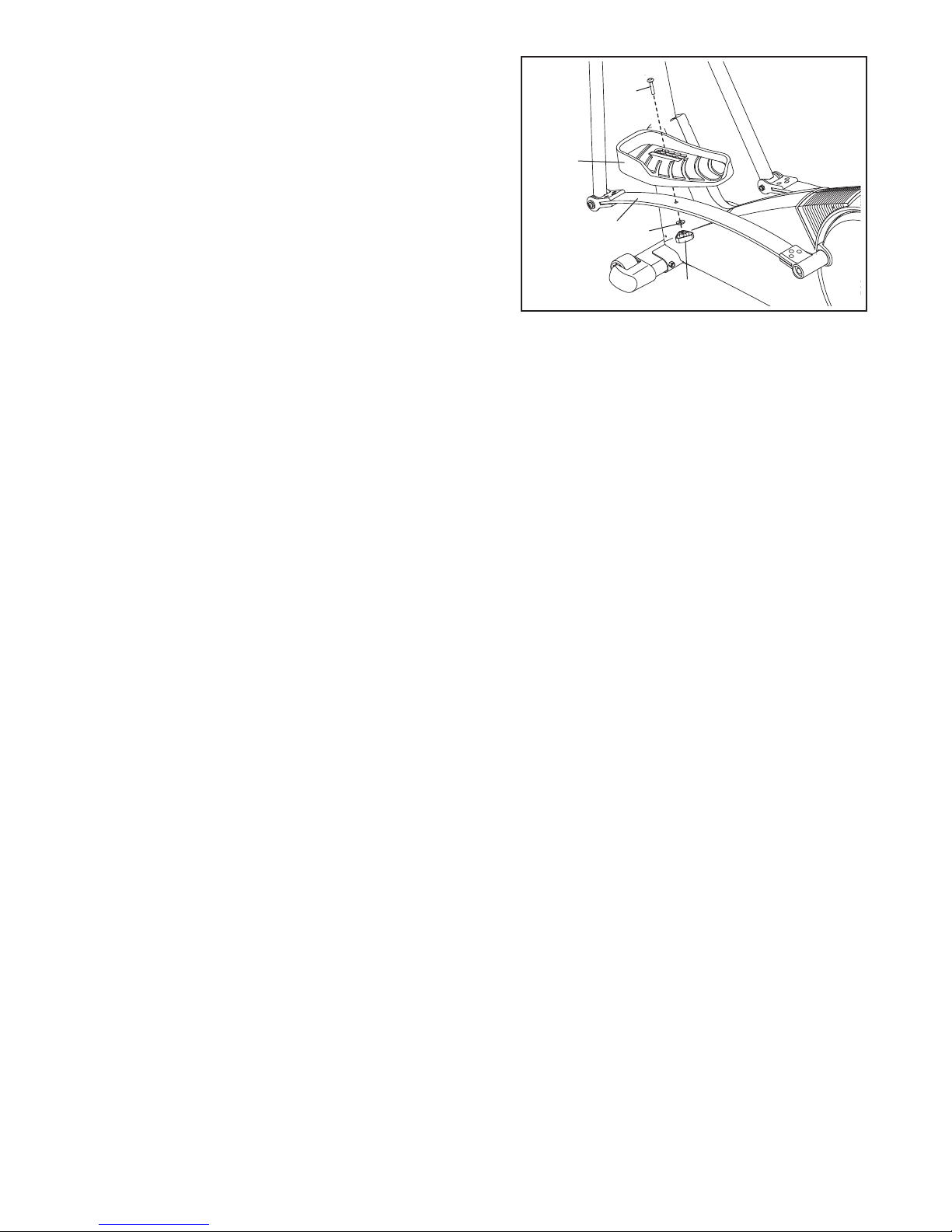
8. Identify the Left Pedal (13). Attach the Left Pedal to the
left Flex Bar (14) with an M10 x 33mm Carriage Bolt
(20), an M10 W
shown. Note: The Left Pedal can be attached in any of
five positions (see HOW
page 9).
Attach the Right Pedal (not shown) in the same way.
Make sure that both Pedals are in the same position.
9. Make sure that all parts of the elliptical crosstrainer are properly tightened. Note: Some hardware may
be left over after assembly is completed. To protect the floor or carpet from damage, place a mat under the
elliptical crosstrainer.
asher (38), and a Pedal Knob (15) as
TO ADJUST THE PEDALS on
8
20
13
14
38
15
8
 Loading...