

Quick Start Guide
TWR-MECH
Mechatronics Board
TOWER SYSTEM
Quick Start Guide
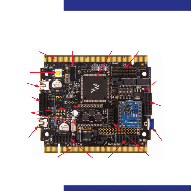
Get to Know the Tower Mechatronics Board
Primary
Connector
SW4
(Reset)
USB
OTG
Touch Panel
Socket
Daughter
Card
Sockets
Debug
USB
2
Secondary
Connector
On/Off Switch
Touch Panel Sockets
MCF52259
Connectors for
Up to Eight Servos
5V Supply
Touch
Panel
Socket
Potentiometer
RS232
Port

TOWER SYSTEM
How to Use the Mechatronics Robot
The Freescale robot (FSLBOT) kit
operates with the Tower mechatronics
(TWR-MECH) board to create an easy-to-
use mechatronics development and
demonstration platform. It is designed
specifically to be used and programmed
with StickOS
users can take programming to new levels
of functionality with the use of CodeWarrior
and Freescale’s Tower System.
®
BASIC. More advanced
TWR-MECH BOARD
Freescale Tower System
The TWR-MECH board is part of the Freescale Tower
System, a modular development platform that enables
rapid prototyping and tool re-use through reconfigurable
hardware. Take your design to the next level and begin
constructing your Tower System today.
3

Quick Start Guide
Step-by-Step Installation Instructions for StickOS
StickOS BASIC is a programming
language and an IDE. It’s specifically
designed to allow those with little or no
programming experience to get up and
running quickly with the TWR-MECH
board. It also provides complex
functionality such as vision filters and
face tracking.
Install StickOS
1
1. Open an Internet browser of your
choice and navigate to
freescale.com/mechbot
2. Select the “Download” tab. Scroll
through the list of downloads and select
FSLBOT_StickOS_IDE. Click “Download”
and save the file to an easily accessible
place on your computer.
3. Decompress the downloaded file.
4

TOWER SYSTEM
Connect the USB Cable
2
1. Plug the included FSLBOT USB cable
into the computer and into the left rear
mini-USB port on the board (labeled
USB OTG).
2. The “Found New Hardware Wizard” will
appear. Choose “Install” from a list or
specific location (Advanced). Click “Next.”
Configure Drivers
3
with Windows® XP
1. Ensure “Search for the best driver in
these locations” is selected. Also, the
“Include this location in the search” box
should be checked. Click “Browse” and
navigate to the folder of the recently
downloaded file. Click “OK,” followed
by “Next.”
5

Quick Start Guide
2. The hardware wizard will install the
needed files to run the Freescale
TWR-MECH.
6
3. Once the hardware wizard has finished,
click “Finish” to complete the installation.
Additional Resources
For more information, visit
freescale.com/mechbot.
Join the online Tower community at
towergeeks.org.

TOWER SYSTEM
Installation Instructions for CodeWarrior
Install CodeWarrior
1
• Downloadandinstallthelatestversion
of CodeWarrior for ColdFire V2 from
freescale.com.
• DownloadtheCodeWarriorsamplecode
for the Freescale mechatronics robot. This
can be found on the Freescale website
on the right hand side of the TWR-MECH
page under “Featured Software.”
Connect the USB Cable
2
Connect the USB cable to the PC and the
other end to the J17 on the TWR-MECH
board, also labeled “DEBUG.”
Configure Drivers
3
Allow PC to automatically configure drivers
if needed. If you have driver problems, please
see the TWR-MECH driver installation guide
located in the sample code folder mentioned
above, or visit pemicro.com/osbdm.
Launch Software
4
Launch CodeWarrior for ColdFire V2.
Close the startup box, and click “File >
Open” to open the sample code.
The file path is: TWR_MECH_FSLBOT_
Cadewarrior_Sample_CODE/ mcf5225x_
SC_FreeBot/build/cw/twr-mcf5225x/TWR
_Mechatronics_MCF5225X_base.mcp.
You are now ready to start programming
with CodeWarrior.
Note: On/Off switch must be in “On”
position for the servos to activate.
Additional Resources
Please see the related documents provided
in the sample code folder, and visit
freescale.com for more information.
7

Quick Start Guide
TWR-S08PT60 Default Jumper Options
The following is a list of all jumper options. The default installed jumper settings are
shown in white text within the violet boxes
Jumper Option Setting Description
Default Clock Mode
J3
Selection (CLKMOD1)
MCU Power
J4
Connection
Clock Input Source
J5
Selection
Default Clock Mode
J6
Selection (CLKMOD0)
Potentiometer
J7
Selection
Serial Flash
J8
Programming Mode
Default Clock Mode
J10
Selection (XTAL)
8
.
1-2 Disable PLL at startup
2-3 Enable PLL at startup
On
Cut-Trace
Cut-Trace
Cut-Trace
Supply 3.3V to MCU
Isolate MCU from power (connect an ammeter to
Off
measure current)
1-2 Connect EXTAL to the on-board crystal
Connect EXTAL to the CLKIN0 signal on the elevator
2-3
connector
1-2 Do not use crystal oscillator at startup
2-3 Use crystal oscillator at startup
On
Connect AN6 to potentiometer
Isolate AN6 from potentiometer
O
1-2
Pull RCON high, allow normal reset behavior
Pull RCON low, as exiting reset give EzPort access to
2-3
flash memory for programming by external device
1-2 Bypass crystal oscillator at startup (if CLKMOD0 = 0)
Enable internal relaxation oscillator at startup
2-3
(if CLKMOD0 = 0)
Off Use crystal oscillator at startup

TOWER SYSTEM
TWR-MECH Jumper Options (continued)
Jumper Option Setting Description
UART Hardware Flow
J11
Control Connections
UART TXD0 Routing
J12
Selection
UART RXT0 Routing
J13
Selection
BDM/JTAG Enable
J14
Selection
TCLK/PSTCLK
J15
Routing Selection
TCLK/PSTCLK/
J16
CLKOUT Routing
Selection
OSBDM Bootloader
J20
Selection
J21 RESET Select
1-2 Connect CTS0 to the RS232 transceiver for flow control
3-4 Connect RTS0 to the RS232 transceiver for flow control
1-2 Connect TXD0 to the RS232 transceiver
2-3 Connect TXD0 to the OSBDM debugger interface circuit
1-2 Connect RXD0 to the transceiver
2-3 Connect RXD0 to the OSBDM debugger interface circuit
1-2
Cut-Trace
Non-Pop
Non-Pop
BDM mode
2-3 JTAG mode
1-2 Connect TCLK/PSTCLK to PSTCLK for BDM mode
2-3 Connect TCLK/PSTCLK to TCLK for JTAG
Connect TCLK/PSTCLK/CLKOUT to TCLK/PSTCLK for
1-2
BDM/JTAG mode
Connect TCLK/PSTCLK/CLKOUT to CLKOUT0 on the
2-3
elevation connector
OSBDM bootloader mode (OSBDM firmware
On
reprogramming)
Off
Debugger mode
On Suspend MCU in reset state (hold RSTIN low)
Off
Release RSTIN so it can be controlled by SW4 to initiate
reset sequences
9

Quick Start Guide
TWR-MECH Jumper Options (continued)
Jumper Option Setting Description
1-2 Connect SERVO_1 PWM signal to servo plug
3-4 Connect SERVO_2 PWM signal to servo plug
5-6 Connect SERVO_3 PWM signal to servo plug
Servo Motor
J22
Signal Selection
Touch Sensor
J40
Interrupt Select
Universal Sensor No. 1
J41
Interrupt No. 1 Select
Universal Sensor No. 1
J42
Interrupt No. 2 Select
Universal Sensor No. 1
J43
Interrupt No. 3 Select
J49 Battery Selection
10
7-8 Connect SERVO_4 PWM signal to servo plug
9-10 Connect SERVO_5 PWM signal to servo plug
11-12 Connect SERVO_6 PWM signal to servo plug
13-14 Connect SERVO_7 PWM signal to servo plug
15-16 Connect SERVO_8 PWM signal to servo plug
On
Cut-Trace
Cut-Trace
Connect IRQ_TOUCH to IRQ7_b to use touch
sensor interrupt
Off Isolate IRQ7_b from touch sensor
On Connect AN0 to IRQ1_b to sense interrupt signal
Off Isolate AN0 from IRQ1_b to measure analog signal
Connect AN1 to IRQ3_b/FEC_MDIO to sense
On
interrupt signal
Isolate AN1 from IRQ3_b/FEC_MDIO to measure analog
Off
signal
Connect AN2 to IRQ5_b/FEC_MDC to sense interrupt
On
signal
Isolate AN2 from IRQ5_b/FEC_MDC to measure analog
Off
signal
1-2
Connect SW1 to BAT1 for 4x AA cells
2-3 Connect SW1 to BAT2 for 7.2V external battery pack

TOWER SYSTEM
11

Quick Start Guide
For more information, visit
freescale.com/Tower
Join the online Tower community at
towergeeks.org
Freescale, the Freescale logo, CodeWarrior and ColdFire are trademarks
or registered trademarks of Freescale Semiconductor, Inc., Reg. U.S. Pat.
& Tm. Off. All other product or service names are the property of their
respective owners. © 2011 Freescale Semiconductor, Inc.
Doc Number: TWRMECHQSG REV1 Agile Number: 926-27081 REV B
 Loading...