

TWR-LCD
Graphical LCD module
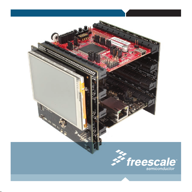
TOWER SYSTEM Quick Start Guide for TWR-LCD
TOWER SYSTEM
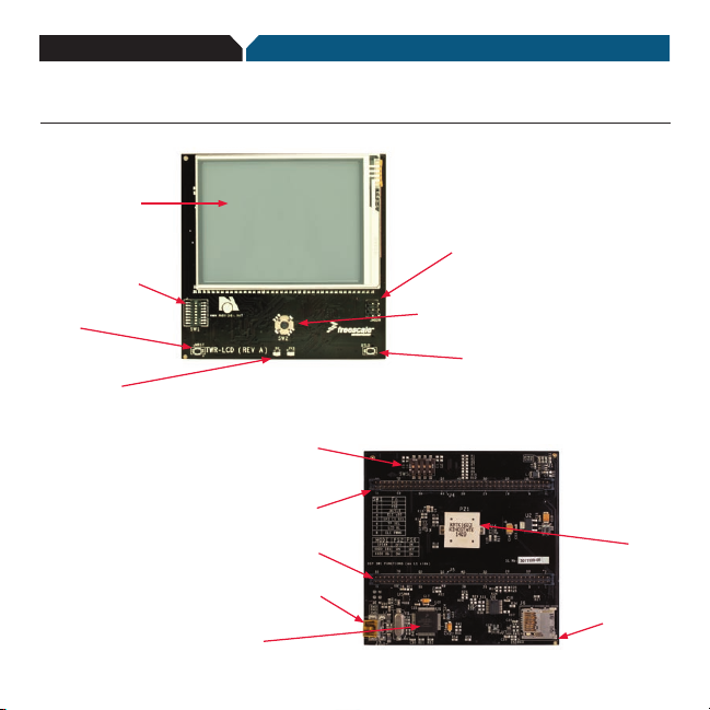
Get to know the TWR-LCD
3.2” QVGA TFT
LCD Display
Configuration
Settings (SW1)
Reset
Push Button
Power LEDs
Touch Panel Isolations
Switches (SW5)
A Side Expansion Port
B Side Expansion Port
Mini-B USB Connector
MCF51JM128
Navigation Switch
JM128
BDM Header
5-way
Bootloader
Push Button
Piezo
Buzzer
microSD
Card Slot
TOWER SYSTEM
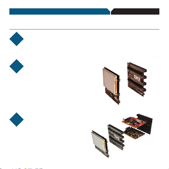
How to attach the TWR-LCD module
STEP
Locate the “functional”
1
Elevator in the
assembled Tower Kit.
STEP
Press the expansion
2
connectors on the
back of the TWR-LCD module
onto the the matching Side
Expansion Port connectors
found on the outer side of the
“functional” Elevator.
STEP
Proceed to the “How
3
to build your Tower”
section to complete the
assembly of your Freescale
Tower System.
Note: Once the TWR-LCD module is
affixed to the “functional” Elevator, it will
be difficult to remove. Removal of the
TWR-LCD module is not recommended.

TOWER SYSTEM
How to build your Tower
STEP
Locate the Elevator modules,
1
identifiable by the four card
edge connectors on each.
STEP
Identify each Elevator module
2
as either “functional” or
“dummy” (written on the
outward facing side of
the board).
STEP
Locate the other modules you
3
will use in your Tower System.
TWR-LCD
Freescale Tower System
The TWR-LCD module is part of the Freescale Tower System, a modular
development platform that enables rapid prototyping and tool re-use through
reconfigurable hardware. Take your design to the next level and begin
constructing your Tower System today.
STEP
Identify the “primary” and
4
“secondary” card edges for
each module (written along
the edge).
STEP
Plug the “primary” card edge
5
of each module into the
“functional” Elevator.
STEP
Place the remaining “dummy”
6
or “functional” Elevator module
onto the “secondary”
card edges.

TOWER SYSTEM Quick Start Guide for TWR-LCD
Step-by-step installation instructions
In this Quick Start Guide, you will learn
how to set up the TWR-LCD module
and run the default GUI demonstration.
STEP
Install software
1
and tools
• InstallCodeWarrior™Development
Studio for Microcontrollers v6.3 from
the included DVD.
STEP
Connect the USB cable
2
cable to the PC and the other end to
the mini-B connector on the TWR-LCD
module. Allow the PC to automatically
configure the USB drivers if needed.
Connect one end of the USB
STEP
Follow the
3
on-screen menu
Explore the features of the GUI demo,
by selecting the menu items with the
touch enabled screen.
STEP
Explore additional
4
resources
Explore the additional documentation and
software resources on the included DVD
and at www.freescale.com/towerlcd.

TOWER SYSTEM
TWR-LCD Jumper Options
The following is a list of all the jumper options. The *default* installed jumper settings are shown in bold
with asterisks.
Configuration
Settings
DIP 1/
DIP 2
DIP 3 JM/ELE
DIP 4 ELE uSD
SW1
DIP 5 SPI CS SEL
DIP 6 TP SEL
DIP 7 LCD BL
DIP 8 ELE PWM0
Option Setting Description
DIP 1
DIP 2
(PS2)
(PS0)
OFF OFF Not a valid setting
PS2/PS0
*OFF* *ON*
ON OFF
ON ON
ON Enables SPI connection from SPI0 of Primary Elevator Connector
*OFF* Enables SPI connection from on-board MCF51JM MCU
ON microSD is connected to the SPI1 of Primary Elevator Connector
*OFF* microSD is connected to the on-board MCF51JM MCU
ON Select SPI0 CS1 as the chip-select for LCD SPI interface
*OFF* Select SPI0 CS0 as the chip-select for LCD SPI interface
ON
*OFF*
*ON* Enables LCD Backlight
OFF Disables LCD Backlight
ON
*OFF* Piezo buzzer is controlled by on-board MCF51JM only
Enables SPI communication mode to the LCD Display. Can be driven
by SPI0 on the Primar y Elevator or by the on-board MCF51JM,
selectable by JM/ELE (SW1-DIP3)
Enables EBI (16-bit mode) communication to the LCD Display
This interface is only accessible from the Tower Elevator MCU
Enables EBI (8-bit mode) communication to the LCD Display
This interface is only accessible from the Tower Elevator MCU
Disables MCF51JM connection to the LCD Touch Panel
Use SW5 to enable ADC connection from Primary Elevator Connector
Enables MCF51JM connection to the LCD Touch Panel
Ensure that SW5 DIP[4:1] are OFF
Piezo buzzer is controlled by PWM0 of Primary Elevator Connector
and on-board MCF51JM

SW2
SW5
5-way
Nav
DIP 1
DIP 2
DIP 3
DIP 4
5-way
Navigation
Switch
Touch Panel
Isolation
(XPLS)
Touch Panel
Isolation
(XMNS)
Touch Panel
Isolation
(YMNS)
Touch Panel
Isolation
(YPLS)
North (Up) Indica tes North signal to onboard MCU
East (Right) Indicates East signal to onboard MCU
South (Down) Indicates South signal to onboard MCU
West (Left) Indicates West signal to onboard MCU
Center (Enter) Indicates Center signal to onboard MCU
ON
*OFF* Disconnects AN4 from Touch Panel
ON
*OFF* Disconnects AN5 from Touch Panel
ON
*OFF* Disconnects AN6 from Touch Panel
ON
*OFF* Disconnects AN7 from Touch Panel
Connects AN4 of Primary Elevator Connector to XPLS Touch
Panel Signal
Connects AN5 of Primary Elevator Connector to XMNS Touch
Panel Signal
Connects AN6 of Primary Elevator Connector to YMNS Touch
Panel Signal
Connects AN7 of Primary Elevator Connector to YPLS Touch
Panel Signal
TOWER SYSTEM Quick Start Guide for TWR-MCF5225X TOWER SYSTEM Quick Start Guide for TWR-LCD

TOWER SYSTEMTOWER SYSTEM
TWR-LCD features
• 3.2”QVGATFTLCDDisplaywithTouchSensitiveOverlay
• DedicatedMCF51JMmicrocontroller
• ExandabletoadditionalTowerMCUsoverEBIorSPI
• microSDcardformemoryexpansion
• Piezobuzzerforaudiblefeedback
To learn more about the TWR-LCD and other modules within the Tower
System, go to www.freescale.com/tower. To become a member of the
online Tower Geeks community, go to www.towergeeks.org.
Freescale, the Freescale logo and CodeWarrior are trademarks or
registered trademarks of Freescale Semiconductor, Inc. in the U.S. and
other countries. All other product or service names are the property of
their respective owners. © Freescale Semiconductor, Inc. 2010.
Doc Number: TWRLCDQSG / REV 0
Agile Number: 926-78436 / REV A
 Loading...