

Page 1

S08
Microcontrollers
freescale.com
LED Lighting Control Using the
MC9S08AW60
Designer Reference Manual
DRM093
Rev. 1
07/2007
Page 2

Page 3
LED Lighting Control using the MC9S08AW60
Designer Reference Manual
by: Dennis Lui, Ernest Chan
Freescale Semiconductor, Inc.
Hong Kong
To provide the most up-to-date information, the revision of our documents on the World Wide Web is the
most current. Your printed copy may be an earlier revision. To verify you have the latest information
available, refer to:
http://www.freescale.com
The following revision history table summarizes changes contained in this document. For your
convenience, the page number designators have been linked to the appropriate location.
Revision History
Date
03/2006 0 Initial release N/A
07/2007 1 Overall edits for grammar, spelling, structure, and style. N/A
Freescale Semiconductor 3
Revision
Level
Description
LED Lighting Control using the MC9S08AW60, Rev. 1
Page
Number(s)
Page 4

Revision History
LED Lighting Control using the MC9S08AW60, Rev. 1
4 Freescale Semiconductor
Page 5

Table of Contents
Chapter 1
Introduction
1.1 Introduction . . . . . . . . . . . . . . . . . . . . . . . . . . . . . . . . . . . . . . . . . . . . . 7
1.2 Features . . . . . . . . . . . . . . . . . . . . . . . . . . . . . . . . . . . . . . . . . . . . . . . 7
1.3 System Overview . . . . . . . . . . . . . . . . . . . . . . . . . . . . . . . . . . . . . . . . 8
1.4 MC9S08AW60 . . . . . . . . . . . . . . . . . . . . . . . . . . . . . . . . . . . . . . . . . . 8
Chapter 2
Hardware Description
2.1 Introduction . . . . . . . . . . . . . . . . . . . . . . . . . . . . . . . . . . . . . . . . . . . . 11
2.2 DEMO9S08AW60LED Features . . . . . . . . . . . . . . . . . . . . . . . . . . . . 12
2.3 DEMO9S08AW60LED Layout . . . . . . . . . . . . . . . . . . . . . . . . . . . . . 12
2.4 Development Support . . . . . . . . . . . . . . . . . . . . . . . . . . . . . . . . . . . . 13
2.5 Power . . . . . . . . . . . . . . . . . . . . . . . . . . . . . . . . . . . . . . . . . . . . . . . . 13
2.6 Reset Switch . . . . . . . . . . . . . . . . . . . . . . . . . . . . . . . . . . . . . . . . . . . 13
2.7 Clock Source . . . . . . . . . . . . . . . . . . . . . . . . . . . . . . . . . . . . . . . . . . . 13
2.8 RS-232 . . . . . . . . . . . . . . . . . . . . . . . . . . . . . . . . . . . . . . . . . . . . . . . 13
2.9 User Options . . . . . . . . . . . . . . . . . . . . . . . . . . . . . . . . . . . . . . . . . . . 14
2.9.1 Pushbutton Switches . . . . . . . . . . . . . . . . . . . . . . . . . . . . . . . . . . 14
2.9.2 LED Indicators . . . . . . . . . . . . . . . . . . . . . . . . . . . . . . . . . . . . . . . 14
2.9.3 ADC Interface . . . . . . . . . . . . . . . . . . . . . . . . . . . . . . . . . . . . . . . . 14
2.9.4 Other I/O Connectors . . . . . . . . . . . . . . . . . . . . . . . . . . . . . . . . . . 15
2.10 LED Driving Board . . . . . . . . . . . . . . . . . . . . . . . . . . . . . . . . . . . . . . 18
2.11 LED Driver Design Procedures . . . . . . . . . . . . . . . . . . . . . . . . . . . . . 19
2.11.1 RGB LED Chip . . . . . . . . . . . . . . . . . . . . . . . . . . . . . . . . . . . . . . . 19
2.11.2 Current Sense Resistor . . . . . . . . . . . . . . . . . . . . . . . . . . . . . . . . 20
2.11.3 Boost Converter . . . . . . . . . . . . . . . . . . . . . . . . . . . . . . . . . . . . . . 20
Chapter 3
Firmware Description
3.1 Introduction . . . . . . . . . . . . . . . . . . . . . . . . . . . . . . . . . . . . . . . . . . . . 23
3.2 PC Control Mode . . . . . . . . . . . . . . . . . . . . . . . . . . . . . . . . . . . . . . . 24
3.3 Standalone Mode . . . . . . . . . . . . . . . . . . . . . . . . . . . . . . . . . . . . . . . 26
3.4 Firmware Files . . . . . . . . . . . . . . . . . . . . . . . . . . . . . . . . . . . . . . . . . 27
Chapter 4
Demo Setup
4.1 Introduction . . . . . . . . . . . . . . . . . . . . . . . . . . . . . . . . . . . . . . . . . . . . 29
4.2 Hardware and Software Setup . . . . . . . . . . . . . . . . . . . . . . . . . . . . . 29
4.2.1 Hardware Setup . . . . . . . . . . . . . . . . . . . . . . . . . . . . . . . . . . . . . . 29
4.2.2 PC Software Setup . . . . . . . . . . . . . . . . . . . . . . . . . . . . . . . . . . . . 29
4.3 Demo Examples . . . . . . . . . . . . . . . . . . . . . . . . . . . . . . . . . . . . . . . . 31
LED Control using the MC9S08AW60, Rev. 1
Freescale Semiconductor 5
Page 6

Table of Contents
4.3.1 Demo 1 - Demonstration Display . . . . . . . . . . . . . . . . . . . . . . . . . 31
4.3.2 Demo 2 - Preset Colors Display . . . . . . . . . . . . . . . . . . . . . . . . . . 32
4.3.3 Demo 3 - Auto White Balance Control . . . . . . . . . . . . . . . . . . . . . 32
4.3.4 Demo 4 - PWM Output Frequency Control . . . . . . . . . . . . . . . . . . 32
4.3.5 Demo 5 - Full Manual Control . . . . . . . . . . . . . . . . . . . . . . . . . . . . 32
4.4 Program the MCU Flash . . . . . . . . . . . . . . . . . . . . . . . . . . . . . . . . . . 33
4.5 Troubleshooting . . . . . . . . . . . . . . . . . . . . . . . . . . . . . . . . . . . . . . . . 33
Appendix A
Schematics
Appendix B
Bill of Materials
LED Control using the MC9S08AW60, Rev. 1
6 Freescale Semiconductor
Page 7

Chapter 1 Introduction
1.1 Introduction
This manual describes a reference design of a multi-color LED lighting control solution by using the
MC9S08AW60 Microcontroller.
Using a microcontroller (MCU) to control the red/green/blue (RGB) color LEDs increases system flexibility
and functionality for the next generation of lighting applications, architectural/entertainment lighting or
LCD backlighting, that require a smart and adaptive control methodology to ensure optimized color space
rendering for various display contents, excellent color contrast for realistic display scene and a consistent
color setting in manufacturing. In many cases, these new applications are controlled by a central control
unit that requires a connectivity interface that can be implemented at a low cost using MCU-based lighting
controller.
A compact light-box with more than a million display colors is implemented to demonstrate the
advantages of using MCU to control RGB color LEDs with different luminosity settings. The average
current through each color LED is controlled by an individual PWM signal generated from MCU and the
LED luminosity is almost in linear relationship with the pulse width of the driving PWM signal. The final
display color is determined on the mix of light emitted by RGB LEDs, so one of the simple methods to set
the light source in different color is changing the RGB PWM duty cycles equal to the corresponding mixing
ratio required for a particular color. In addition, a serial control protocol with user interface is also
developed as a communication link to control and monitor system parameters through a personal
computer.
All hardware schematic diagrams and firmware source codes are available as reference materials.
1.2 Features
• Apply for architectural/entertainment lighting or LCD backlighting applications
• Exceptional color mixing
• Pre-set or dynamic RGB colors
• High resolution on dimming control
• Automatic white balance tracking on dimming
• Flexible connectivity interface
• User friendly control menu
LED Lighting Control using the MC9S08AW60, Rev. 1
Freescale Semiconductor 7
Page 8
Introduction
PWM
SCI
KBI
AW60
RGB
PWM
ADC
Button Switch
Detection
GPIO Port
RS232
Interface
To PC
Power Supply & Regulator
DC/DC
Converter
Blue LEDs
I/O Control
Red LEDs
Green LEDs
PWM
SCI
KBI
AW60
RGB
PWM
ADC
Button Switch
Detection
GPIO Port
RS232
Interface
To PC
Power Supply & Regulator
DC/DC
Converter
Blue LEDs
I/O Control
Red LEDs
Green LEDs
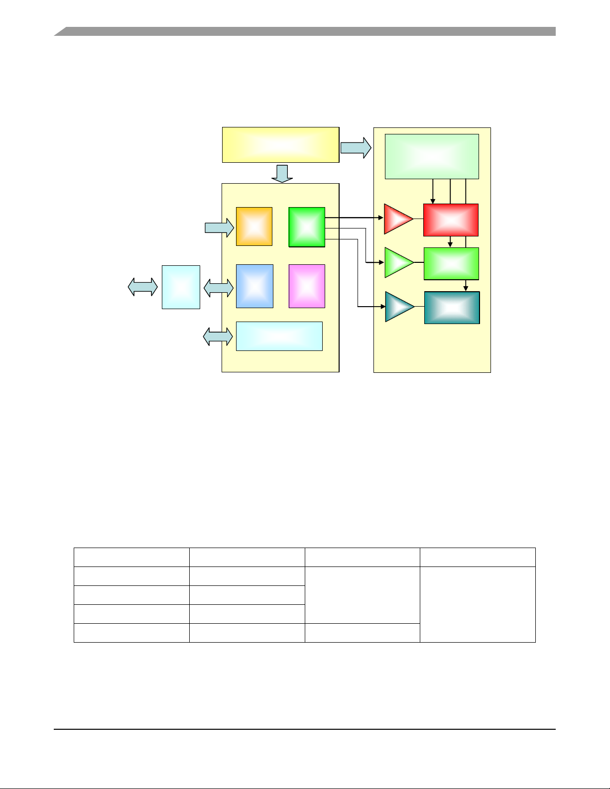
1.3 System Overview
A block diagram of the system is shown in Figure 1-1.
Figure 1-1 . System Block Diagram
1.4 MC9S08AW60
The MC9S08AW60, MC9S08AW48, MC9S08AW32, and MC9S08AW16 are members of the low-cost,
high-performance HCS08 family of 8-bit microcontroller units (MCUs). All MCUs in the family use the
enhanced HCS08 core and are available with a variety of modules, memory sizes, memory types, and
package types. Refer to Table 1-1 for memory sizes and package types.
Table 1-2 summarizes the peripheral availability per package type for the devices available in the
MC9S08AW60/48/32/16 series.
Table 1-1. Devices in the MC9S08AW60/48/32/16 Series
Device Flash RAM Package
MC9S08AW60 63,280
MC9S08AW48 49,152
MC9S08AW32 32,768
MC9S08AW16 16,384 1024
2048
64 QFP
64 LQFP
48 QFN
44 LQFP
LED Lighting Control using the MC9S08AW60, Rev. 1
8 Freescale Semiconductor
Page 9

Table 1-2. Peripherals Available per Package Type
Package Options
Feature 64-Pin 48-Pin 44-Pin
ADC 16-CH 8-CH 8-CH
IIC Yes Yes Yes
IRQ Yes Yes Yes
KBI1 8 7 6
S C I 1 Ye s Ye s Ye s
S C I 2 Ye s Ye s Ye s
SPI1 Yes Yes Yes
TPM1 6-CH 4-CH 4-CH
TPM1CLK Yes No No
TPM2 2-CH 2-CH 2-CH
TPM2CLK Yes No No
MC9S08AW60
I/O Pins 54 38 34
LED Lighting Control using the MC9S08AW60, Rev. 1
Freescale Semiconductor 9
Page 10

Introduction
LED Lighting Control using the MC9S08AW60, Rev. 1
10 Freescale Semiconductor
Page 11
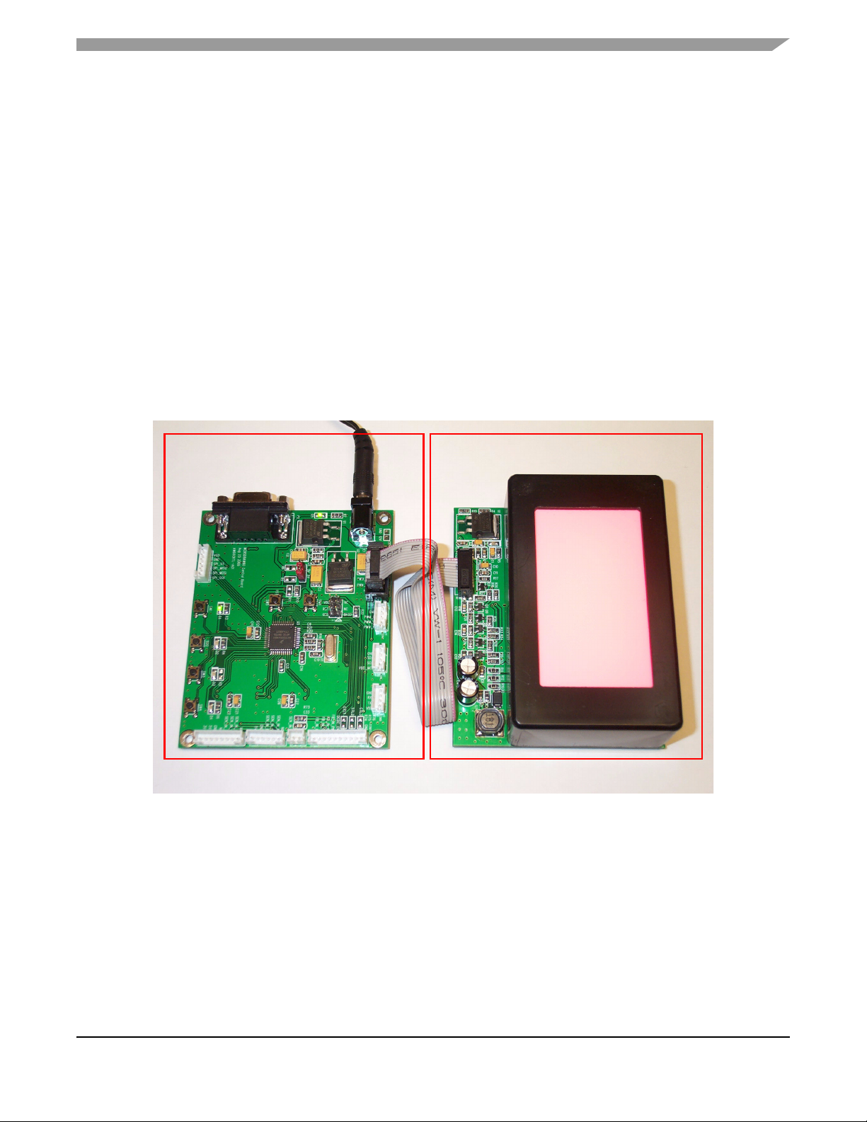
Chapter 2
AW60 Control Board
RGB LED Driving Board
Hardware Description
2.1 Introduction
The system consists of a MCU control board and a LED driving board. The MCU control board,
DEMO9S08AW60LED, is one of the demonstration boards for the Freescale MC9S08AW60. This board
allows easier developmet of code for LED control applications, architectural/entertainment lighting or LCD
backlighting. The on-board serial interface allows you to control and monitor the system status via the
RS232 serial port connection. The separated LED light-box with driving circuitries is also available as a
whole demo kit to demonstrate how to do the color mixing and see the visual effects on changing different
type of parameter settings.
Figure 2-1. Light-Box Demo
LED Lighting Control using the MC9S08AW60, Rev. 1
Freescale Semiconductor 11
Page 12
Hardware Description
2.2 DEMO9S08AW60LED Features
• MC9S08AW60 CPU
– 44 pin LQFP package
– 20 MHz Internal Bus Frequency
– 60 Kbytes of on-chip in-circuit programmable FLASH
– 2 Kbytes of on-chip RAM
– 8-channel, 10-bit analog-to-digital converter
– Two SCI modules
– SPI module
2
–I
C module
– 6-pin keyboard interrupt (KBI) module
– 34 general-purpose input/output (I/O) pins
• External power jack for DC power supply (+12 VDC)
• Four pushbutton user switches
• Four LEDs connected to I/O port
• Master reset switch
• RGB PWM output port
• Optical sensor input port
• On-board RS-232 serial port
• 100mm x 80mm board size
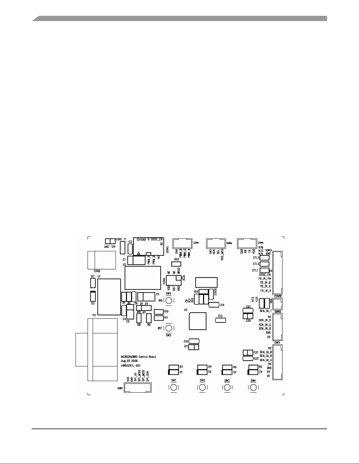
2.3 DEMO9S08AW60LED Layout
Figure 2-2. DEMO9S08AW60LED Top Side
LED Lighting Control using the MC9S08AW60, Rev. 1
12 Freescale Semiconductor
Page 13
Development Support
2.4 Development Support
Application development and debug for the MC9S08AW60 is supported through a 6-pin BDM header
(CON8). The pinout is as follows:
Table 2-1. BDM Connector (CON8) Pinout
BKGD 1 2 GND
NC 3 4 RESET
NC 5 6 V
DD
2.5 Power
The DEMO9S08AW60LED is powered externally through the barrel connector CON2. This connector is
a 2.5 mm, center positive connector. Voltage supplied through this connector should be positive 12 volts
DC. This is also the supply voltage for the LED light box.
The DEMO9S08AW60LED can be run with V
set to 5 or 3 volts. To run the board at 3V, move jumper
DD
JP1 to the 1-2, 3V position.
LED D5 turns green to let you know that power has been correctly applied to the board.
2.6 Reset Switch
The reset switch (SW5) provides a way to apply a reset to the MCU. The reset switch is connected directly
to the RESET
signal of the MCU. A 10 kΩ pullup resistor to VDD on the RESET signal allows for normal
operation. When the reset switch is pressed, the RESET signal is grounded and the MCU recognizes a
reset.
2.7 Clock Source
An on-board 16 MHz crystal (X1) is connected between the XTAL and EXTAL pins of the MCU. This offers
flexibility on clock source selection. Refer to the MC9S08AW60 data sheet for details on how to use the
internal clock generation (ICG) module to generate the system clocks for the MCU.
2.8 RS-232
An RS-232 translator provides RS-232 communication on COM connector P2. This connector is a 9-pin
Dsub right angle connector. TXD and RXD signals are routed from the MCU to the RS-232 transceiver.
Table 2-2 . RS-232 Connections
MCU Port COM Signal I/O Port Connector
PTE0/TXD1 TXD OUT P2-2
PTE1/RXD1 RXD IN P2-3
LED Lighting Control using the MC9S08AW60, Rev. 1
Freescale Semiconductor 13
Page 14
Hardware Description
2.9 User Options
The DEMO9S08AW60LED includes various input and output devices to assist in application
development. These devices include four pushbutton switches, four LEDs, and an operational amplifier
with RC filter connected at each ADC input channel for signal amplification and filtering.
2.9.1 Pushbutton Switches
Four pushbutton switches provide momentary active low input for user applications. The table below
describes the pushbutton switch connections.
Table 2-3. Pushbutton Switches (SW1-SW4) Connections
Switch MCU Port
SW1 PTG0/KBI0
SW2 PTG1/KBI1
SW3 PTG2/KBI2
SW4 PTG3/KBI3
2.9.2 LED Indicators
Four green LED indicators (D1-D4) are provided to assist during code development. The LEDs are active
low and illuminated when a logic low signal is driven from the MCU port pin. Two of the LEDs are
connected to port A, and the other two are connected to Port C. The connections are described below:
Table 2-4. LEDs (D1-D4) Connections
LED MCU Port
D1 PTA0
D2 PTA1
D3 PTC2
D4 PTC4
2.9.3 ADC Interface
Eight operational amplifiers are provided to assist users in developing applications with feedback control
signals. For examples, the signal generated by an optical sensor in LED backlight system should be
scaled to a level matched with the ADC input range without any saturation. Each operational amplifier can
be configured as an inverting or non-inverting amplifier with variable gain setting by different resistor
connections. A RC filter is also connected at each output for noise filtering.
NOTE
The maximum operational amplifier output voltage should be limited to the
V
voltage applied to MCU to prevent any damage on input port.
DD
LED Lighting Control using the MC9S08AW60, Rev. 1
14 Freescale Semiconductor
Page 15

User Options
2.9.4 Other I/O Connectors
One user assignable and eight pre-defined I/O connectors are available to help users connect the board
into their target system.
Table 2-5. IIC Port
CON5 Signal Name Remarks
Pin 1 NC
Pin 2 SCL
Pin 3 SDA
Pin 4 GND —
Install a zero ohm resistor in the R14 footprint to
connect V
Connected to MCU PTC0/SCL1
10 kΩ pullup to V
Connected to MCU PTC1/SDA1
10 kΩ pullup to V
DD
DD
DD
Table 2-6. SCI Port
CON6 Signal Name Remarks
Pin 1 NC
Pin 2 SCI_TX Connected to MCU PTE0/TXD1
Pin 3 SCI_RX Connected to MCU PTE1/RXD1
Pin 4 GND —
Install a zero ohm resistor in the R15 footprint to
connect V
DD
Table 2-7. SPI Port
CON7 Signal Name Remarks
Pin 1 NC
Pin 2 GND —
Pin 3 SPI_SS Connected to MCU PTE4/SS1
Pin 4 SPI_MISO Connected to MCU PTE5/MISO1
Pin 5 SPI_MOSI Connected to MCU PTE6/MOSI1
Pin 6 SPI_SCK Connected to MCU PTE7/SPSCK1
LED Lighting Control using the MC9S08AW60, Rev. 1
Freescale Semiconductor 15
Install a zero ohm resistor in the R16 footprint to
connect V
DD
Page 16

Hardware Description
Table 2-8. PWM Port
CON4 Signal Name Remarks
Pin 1 PWM R Connected to MCU PTF0/TPM1CH2
Pin 2 PWM G Connected to MCU PTF1/TPM1CH3
Pin 3 PWM B Connected to MCU PTE2/TPM1CH0
Pin 4 GND —
Table 2-9. LED Light Box Interface
CON3 Signal Name Remarks
Pin 1 & 2 12V 12V power for LED light box
Pin 3 & 4 GND —
Pin 5 PWM R Connected to MCU PTF0/TPM1CH2
Pin 6 PWM G Connected to MCU PTF1/TPM1CH3
Pin 7 PWM B Connected to MCU PTE2/TPM1CH0
Connected to MCU PTC3/TXD2
Pin 8 DCDC_EN
Pin 9 & 10 NC —
Reserved pin for DC to DC converter ON/OFF
control
Table 2-10. Sensor Interface Type A
CON10 Signal Name Remarks
Pin 1 5V Sensor supply voltage
Pin 2 GND —
Pin 3 SEN_IN_B
Pin 4 SEN_IN_G
Pin 5 SEN_IN_R
Pin 6 NC —
Sensor input (Blue), Connected to MCU
PTB2/ADP2 through operational amplifier U5B
Sensor input (Green), Connected to MCU
PTB1/ADP1 through operational amplifier U5A
Sensor input (Red), Connected to MCU
PTB0/ADP0 through operational amplifier U5D
LED Lighting Control using the MC9S08AW60, Rev. 1
16 Freescale Semiconductor
Page 17

Table 2-11. Sensor Interface Type H
CON11 Signal Name Remarks
Pin 1 3V Sensor reference voltage
Pin 2 5V Sensor supply voltage
Pin 3 GND —
Pin 4 NC —
User Options
Pin 5 SEN_IN_G
Pin 6 SEN_IN_R
Pin 7 SEN_IN_B
Pin 8 NC —
Sensor input (Green), Connected to MCU
PTB1/ADP1 through operational amplifier U5A
Sensor input (Red), Connected to MCU
PTB0/ADP0 through operational amplifier U5D
Sensor input (Blue), Connected to MCU
PTB2/ADP2 through operational amplifier U5B
NOTE
Connectors Type A and H share the same connection, so either one of the
sensor interfaces can be used for sensor input.
Table 2-12. Temperature Sensor Input
CON12 Signal Name Remarks
Pin 1 SEN_IN_T
Pin 2 GND —
10 kΩ pullup to V
PTB3/ADP3 through operational amplifier U5C
, Connected to MCU
DD
Table 2-13. User Assignable Input
CON13 Signal Name Remarks
Pin 1 FB_IN_R
Pin 2 FB_IN_G
Pin 3 FB_IN_B
Pin 4 FB_IN_PW
Pin 5 DCDC_EN
Pin 6 DCDC_ER Connected to MCU PTC5/RXD2
LED Lighting Control using the MC9S08AW60, Rev. 1
Freescale Semiconductor 17
Connected to MCU PTD0/ADP8 through
operational amplifier U6D
Connected to MCU PTD1/ADP9 through
operational amplifier U6A
Connected to MCU PTD2/ADP10 through
operational amplifier U6B
Connected to MCU PTD3/ADP11 through
operational amplifier U6C
Connected to MCU PTC3/TXD2 and connector
CON3 pin 8
Page 18

Hardware Description
Table 2-13. User Assignable Input (Continued)
CON13 Signal Name Remarks
Pin 7 DCDC_CTL1 Connected to MCU PTF4/TPM2CH0
Pin 8 DCDC_CTL2 Connected to MCU PTF5/TPM2CH1
Pin 9 DCDC_CTL3 Connected to MCU PTE3/TPM1CH1
Pin 10 GND —
2.10 LED Driving Board
In general, LEDs have a nonlinear I-V behavior and current limitation is required to prevent the power
dissipation to exceed a maximum limit. Therefore, the ideal source for LED driving is a constant current
source. A linear type LED driver is used in this reference design and the block diagram is shown in
Figure 2-4. The major advantage of linear driver is fast turn ON and OFF response times to support high
frequency PWM dimming method and wide range control on dimming level. An integrated DC-to-DC
boost converter (MC34063) generates the high voltage required for LED driving in series and is shared
with RGB channels, but the drawback is the power loss on R channel is higher than G or B channels.
Individual DC-to-DC block should be used for each channel in power sensitive applications.
LED Lighting Control using the MC9S08AW60, Rev. 1
18 Freescale Semiconductor
Page 19

LED Driver Design Procedures
Vout = 30V
DC-to-DC
Boost
Converter
(MC34063)
V
REF
8 LEDs
Rs
Driver R
Driver G
Driver B
8 LEDs
8 LEDs
V
LED
x 8
V
DROP
V
RS
I
LED
= 50mA
Vin = 12V
R-Channel
PWM
G-Channel
PWM
B-Channel
PWM
Vout = 30V
DC-to-DC
Boost
Converter
(MC34063)
V
REF
8 LEDs
Rs
Driver R
Driver G
Driver B
8 LEDs
8 LEDs
V
LED
x 8
V
DROP
V
RS
I
LED
= 50mA
Vin = 12V
R-Channel
PWM
G-Channel
PWM
B-Channel
PWM
Eight pieces of 3-in-1 RGB LED chips connected in series are used to form the multi-color light source.
The LED chips are arranged in 2 x 4 format and each RGB LED string is driven by a separated constant
Figure 2-3. DC-to-DC Boost Converter and Linear LED Driver
current source. The average current through each RGB LED is controlled by an individual PWM signal
generated from MCU. The final output color is determined by the mix of light emitted by RGB LEDs that
are almost in linear relationship with PWM pulse width. An optical diffuser film should be placed on top of
the display window for color mixing and brightness uniformity enhancement.
2.11 LED Driver Design Procedures
This section presents guidelines for selecting external components for DC-to-DC boost converter and
linear drivers.
2.11.1 RGB LED Chip
The system is designed to drive eight pieces of RGB LED chips connected in a series. Assume the LED
current for each color is 50mA and forward voltage is 2.3V for red LED and 3.3V for green and blue LEDs.
LED Lighting Control using the MC9S08AW60, Rev. 1
Freescale Semiconductor 19
Page 20

Hardware Description
2.11.2 Current Sense Resistor
The value of the current sense resistor RS is determined by two factors: power dissipation on RS and the
reference level V
but the detection of a feedback signal in operational amplifier is more difficult.
for operational amplifier non-inverting input. Smaller RS reduces power dissipation,
REF
The voltage V
across the current sense resistor RS is directly proportional to the current I
RS
LED. In closed-loop condition, V
to the reference voltage V
Setting V
Power dissipation on R
to 1V and RS equals 20Ω, the LED current I
REF
S
divided by the current sense resistor RS.
REF
is around 50mW, I2R = (50mA)2 × 20Ω, which is reasonable compared to total
is equal to the reference level V
RS
LED
, so the LED current I
REF
is equal to 50mA.
LED
is equal
LED
through
LED power.
2.11.3 Boost Converter
The switching regulator MC34063 from On Semiconductor is a monolithic circuit containing the primary
functions required for DC-to-DC converters. It can be incorporated in boost converter application with
minimum number of external components.
Boost Converter Calculations:
Output voltage V
Output current Iout > 50 mA x 3
Set V
= 12 V, V
in
Refer to equations in Figure 2-4 to calculate the values for inductor and other external components.
> (V
OUT
= 30 V, and I
out
x 8) + VRS + V
LED
= 175 mA
out
(set maximum linear drop to 2 V)
DROP
LED Lighting Control using the MC9S08AW60, Rev. 1
20 Freescale Semiconductor
Page 21

LED Driver Design Procedures
Figure 2-4. Equations for Boost Converter
= Saturation voltage of the output switch.
V
sat
= Forward voltage drop of the output rectifier.
V
F
V
- Nominal input voltage.
in
V
- Desired output voltage.
out
- Desired output current.
I
out
f
- Minimum desired output switching frequency.
min
V
ripple(pp)
- Desired peak-to-peak output ripple voltage.
For further information, refer to On Semiconductor’s datasheet.
LED Lighting Control using the MC9S08AW60, Rev. 1
Freescale Semiconductor 21
Page 22

Hardware Description
LED Lighting Control using the MC9S08AW60, Rev. 1
22 Freescale Semiconductor
Page 23

Chapter 3
Display control menu through
SCI
Yes
No
Initialization
PC Control Mode
Operation?
Enable I/O for PCB button
detection
Yes
No
Valid command from PC?
Process commands and adjust PWM
output
Yes
No
Any PCB button
pressed?
Adjust PWM output according to button
event
*Standalone demo box
without PC control
Display control menu through
SCI
YesYes
No
InitializationInitialization
PC Control Mode
Operation?
Enable I/O for PCB button
detection
YesYes
No
Valid command from PC? Valid command from PC?
Process commands and adjust PWM
output
YesYes
No
Any PCB button
pressed?
Any PCB button
pressed?
Adjust PWM output according to button
event
*Standalone demo box
without PC control
Firmware Description
3.1 Introduction
The MCU firmware in this LED lighting control design is responsible for:
• Controlling timer channels for the RGB LED color PWM output
• Communicating with the host PC for receiving command and data input/output
• Operating as a standalone LED box through on board buttons
Figure 3-1 and Figure 3-2 shows the firmware flow. The LED box can operate in PC control operation
mode or standalone operation mode.
Freescale Semiconductor 23
Figure 3-1. Firmware Flow: Main Program
LED Lighting Control using the MC9S08AW60, Rev. 1
Page 24

Firmware Description
Prompt for green channel PWM input and calculate the
two remaining channels’ PWM values according to
existing color temperature
Adjust PWM width in next PWM cycle
PWM value input to one channel
Yes
Get the other two channel
values from user input
Auto White balance?
No
Prompt for green channel PWM input and calculate the
two remaining channels’ PWM values according to
existing color temperature
Adjust PWM width in next PWM cycle
Adjust PWM width in next PWM cycle
PWM value input to one channelPWM value input to one channel
Yes
Get the other two channel
values from user input
Get the other two channel
values from user input
Auto White balance?Auto White balance?
No
Figure 3-2. Firmware Flow: PWM Adjustment
3.2 PC Control Mode
Every time the MCU is powered up, the firmware detects the status of SW1. The LED lighting control box
is operated in PC control mode if SW1 is not being pressed.
In this mode, you control the LED output through the host PC. The MCU uses the serial communication
interface (SCI) module to communicate to the COM port of the host PC.
After entering this mode, the MCU sends out a number of string characters to the PC COM port. These
strings are the contents of the user interface menu displayed in the PC screen. This user interface menu
guides you on how to control the LED box by different function keys. The MCU also sends out existing
PWM control parameters to the host for display. For examples, parameters such as existing RGB PWM
output values, white balance mode, and PWM frequency are displayed. Figure 3-3 shows the PC screen
for the user control menu.
LED Lighting Control using the MC9S08AW60, Rev. 1
24 Freescale Semiconductor
Page 25

PC Control Mode
Figure 3-3. User Interface Menu
When the MCU receives a control command or PWM input data from the PC, the firmware interprets the
information to take the corresponding actions. It may update the output PWM values in next PWM duty
or delivery of the corresponding LED control parameter back to the PC. Three timer channels in the
timer 1 module are configured to edge-aligned PWM operation mode. This generates the PWM signals
for the RGB color channels.
By the proper control of the RGB channel PWM, the LED box can provide different lighting effects.
If you select the white balance mode to AUTO, the LED output gives a white color output. The firmware
retains control of the RGB PWM ratio based on the preset white color. You can adjust the output
brightness by pressing the + or − key in the host PC keyboard. Alternatively, you can input a green
channel PWM value and the firmware calculates the blue and red PWM values to give the resultant
intensity.
A demonstration display feature is available. After enabling this feature, the firmware adjusts RGB PWM
so the light box switches among different preset colors, delivery fade in and fade out lighting effects, etc.
You can also set the PWM to different frequencies. At a lower PWM frequency, such as 30 Hz, the flicking
phenomenon is more noticeable. This phenomenon can be minimized or removed by setting the PWM
frequency to a higher value.
There are examples at the end of this section showing how to control the LED box through the host PC.
LED Lighting Control using the MC9S08AW60, Rev. 1
Freescale Semiconductor 25
Page 26

Firmware Description
3.3 Standalone Mode
When the LED box is powered up with SW1 being pressed, it enters standalone mode. When compared
to the PC control mode, this standalone mode can act as a quick and simple demo that does not require
a host PC. The control of the LED light box can be done through the onboard buttons. However, the PC
control mode can have more control on the PWM output.
The functions of the buttons are as follows:
• SW6 (IRQ): Demonstration Display Enable/Disable
If SW6 is pressed, the LED box enters the demonstration display state where certain preset colors
display sequentially with some other lighting effects. The demonstration mode can be exit by
pressing SW6 again.
• SW1: Preset Colors Toggle
Whenever SW1 has been pressed and released, the LED box toggles to another preset color. The
LED1 lights up while LED2 turns off.
• SW2: Auto White Balance Control
If SW2 has been pressed, the LED box turns to auto white balance state and give a white color.
The small on board LED2 lights up while LED1 turns off, indicating an auto white balance state.
There are two preset white color with different color temperatures available for selection. To swap
between different preset color temperatures, press the SW2 button once more. The auto white
balance state can be turn off by pressing SW1.
• SW3: Decrease Brightness
The output brightness increases if SW3 has been pressed.
• SW4: Increase Brightness
The output brightness decreases if SW4 has been pressed.
• SW1+SW2: PWM Frequency Selection
The Output PWM Frequency can be changed with following steps:
1. Press and hold SW1
2. Press SW2
3. Release SW2
4. Release SW1
After performing the above action, the output PWM frequency can be changed. There are three
preset settings available, 30 Hz, 120 Hz, and 600 Hz. For examples, after changing from 30 Hz to
120 Hz using above steps, it can set the PWM to 600 Hz by applying the above steps again.
NOTE
The output brightness is changed after changing the frequency. As the
PWM output values remain the same, a change in PWM frequency modifies
the PWM duty as well.
The PWM frequency selection steps above are invalid if the LED box is
running at demonstration display state. In addition, the PWM frequency is
changed to the default value of 120 Hz after the demonstration display state
has been exited by pressing SW6.
LED Lighting Control using the MC9S08AW60, Rev. 1
26 Freescale Semiconductor
Page 27

Firmware Files
3.4 Firmware Files
Below is a list of the C files in the firmware
Main.c
• Programs entry point and determination of operation mode, i.e. PC control mode or standalone
operation mode
• System initialization
• Common functions used in different firmware modules
Menu.c
• Takes care of high level user interface communication with the PC host.
• Interprets the received PC commands or data and initiate the corresponding action. The user
interface menu contents can be modified or edited in this file.
SCI.c
• Takes care of low level SCI hardware for communication between the PC. Functions that
accessing the SCI registers are included in this file.
• String management for input and output functions used in the Menu.c
ISR.c
• Interrupt services routines for different hardware modules
• Timer 1 is used for the PWM channels for the three RGB output color
• Timer 2 is used for generating a periodical interrupt that used in the demonstration display feature
• IRQ interrupts for enabling or disabling of demonstration display in the standalone operation mode.
• KBI interrupts for on board buttons detection
• Functions for generating certain display effects are included in this file
Keyinput.c
• For operation of standalone mode without the host PC
LED Lighting Control using the MC9S08AW60, Rev. 1
Freescale Semiconductor 27
Page 28

Firmware Description
LED Lighting Control using the MC9S08AW60, Rev. 1
28 Freescale Semiconductor
Page 29

Chapter 4 Demo Setup
4.1 Introduction
This section shows how to connect the DEMO9S08AW60LED board to your PC, run the demo program,
and how to program the board with the source code. The source code can be download from the
Freescale website.
4.2 Hardware and Software Setup
The DEMO9S08AW60LED is shipped with the demo program stored in on-chip flash memory. Use
Figure 2-2 as a guide to do the setup.
4.2.1 Hardware Setup
1. Check the jumper setting and make sure jumper JP1 on DEMO9S08AW60LED board is set to the
5V (2-3) position.
2. Connect the 2x5 pin ribbon flat cable at LED light box to connector CON3 on
DEMO9S08AW60LED board.
3. Connect a serial cable to the PC or notebook and then to the DEMO9S08AW60LED board.
4. Power up the demo through the DC jack connector CON1 on DEMO9S08AW60LED board. The
supply voltage is 12V DC and LED D5 should be on.
5. Press SW5 to reset the MCU. The LED light box demo enters PC control mode. (Make sure SW1
is not pressed during reset.)
4.2.2 PC Software Setup
1. Open up a terminal window from within Windows XP by clicking on Start → All Programs →
Accessories → Communications → HyperTerminal
2. Give your terminal connection a name (such as AW60_Control) and click the OK button.
3. In the Connect using pulldown, select the COM port you connected your serial cable to, and click
the OK button.
4. In the Port Settings window, click the OK button after entering the following settings:
Bits per second: 9600
Data bits: 8
Parity: None
Stop bits: 1
Flow control: None
5. Make sure Echo typed characters locally is NOT selected under the ASCII Setup pop-up menu,
see Figure 4-1.
6. After configuring HyperTerminal, the LED Control Menu screen appears as shown in Figure 4-2.
LED Lighting Control using the MC9S08AW60, Rev. 1
Freescale Semiconductor 29
Page 30

Demo Setup
Figure 4-1. Echo Typed Characters Setting
LED Lighting Control using the MC9S08AW60, Rev. 1
30 Freescale Semiconductor
Page 31

Demo Examples
Figure 4-2. LED Control Menu
NOTE
Make sure the HyperTerminal window is selected all the time by moving the
mouse pointer inside the window and clicking the left mouse button (the top
color bar of the terminal window is then blue instead of grey). Otherwise, no
function key command is sent to the LED lightbox.
4.3 Demo Examples
Several examples are given here on showing how to use the LED box under the PC control.
4.3.1 Demo 1 - Demonstration Display
1. Press the reset button SW5 on DEMO9S08AW60LED board. The LED control menu screen
appears (Figure 4-2).
2. Press letter D in the PC keyboard to enter demonstration display operation.
3. In this display state, the LED light box switches among different colors automatically and delivers
other lighting effects.
NOTE
Press any other key to exit demonstration display. Press D to enter
demonstration display again.
LED Lighting Control using the MC9S08AW60, Rev. 1
Freescale Semiconductor 31
Page 32

Demo Setup
4.3.2 Demo 2 - Preset Colors Display
1. Press the tab key in the PC keyboard.
2. The output is switched to another preset color after the tab key has been pressed each time.
NOTE
You can adjust the output color any time through the control menu.
4.3.3 Demo 3 - Auto White Balance Control
1. Press F until PWM frequency is set to 120 Hz.
2. Press W to toggle to AUTO white balance control.
3. Type 2000 at line of input green. The green PWM output value should then show 2000.
4. The red and blue PWM values are adjusted automatically to keep the output at the existing color
temperature.
Note:
Pressing T can change the output to another preset color temperature.
Pressing the
intensity. Use the
+
or − key can gradually increase or decrease the output
+
or − keys from the main keyboard area instead of those
near the NUM lock key pad.
Max PWM input range is decreased if setting to a higher PWM frequency.
4.3.4 Demo 4 - PWM Output Frequency Control
1. Press W to toggle the output to AUTO mode.
2. Pressing F can switch the PWM output among different preset frequencies.
3. The flicking phenomenon is more significant at the lower frequency such as at 30 Hz. The flicking
can be removed by setting PWM to higher frequencies.
NOTE
The output brightness is changed after changing the frequency. As the
PWM output values remain the same, a change in PWM frequency modifies
the PWM duty as well.
As the frequency increases, the max allowable PWM input range
decreases because the PWM value for 100% on-duty becomes smaller.
4.3.5 Demo 5 - Full Manual Control
1. Press F until PWM frequency change to 120Hz
2. Press W to toggle the output to MANUAL mode.
3. Press R to switch to manual red channel input.
4. Type 2000 at the Input red line.
5. Press G to switch to manual green channel input.
6. Type 0000 at the Input green line.
7. Press B to switch to manual blue channel input.
8. Type 2000 at the input blue line.
9. The output color is purple. You can repeat the steps with different PWM values for different output
colors and intensities.
LED Lighting Control using the MC9S08AW60, Rev. 1
32 Freescale Semiconductor
Page 33

Program the MCU Flash
NOTE
Max PWM input range is decreased when setting to a higher PWM
frequency. With the same PWM values, increasing frequency (i.e. shorter
period) increases brightness because the PWM on-duty increases.
When typing HEX PWM input values, use only capital letters for the input
of A–F.
4.4 Program the MCU Flash
The DEMO9S08AW60LED board allows you to program the MCU flash and debug applications via the
BDM connection.
1. Download the source code file from Freescale web site, save it to your PC, and extract the files to
a working directory on your machine.
2. Open CodeWarrior HC(S)08 v5.1 and open the LED_box.mcp project file.
3. Open main.c in the sources folder by clicking the plus sign next to the sources folder and then
double clicking on main.c. This is the application code.
4. Connect the BDM cable from your development tools to the DEMO9S08AW60LED board (CON8).
5. Connect a serial cable to the PC and then to the DEMO9S08AW60LED board.
6. Power up the demo through the DC jack connector CON1 on DEMO9S08AW60LED board.
7. Open up a terminal window from within Windows XP by clicking on Start → All Programs →
Accessories → Communications → HyperTerminal
8. Give your terminal connection a name (such as AW60_Control) and click the OK button.
9. In the Connect using pulldown, select the COM port you connected your serial cable to, and click
the OK button.
10. In the Port Settings window, click the OK button after entering the following settings:
Bits per second: 9600
Data bits: 8
Parity: None
Stop bits: 1
Flow control: None.
11. In the Freescale CodeWarrior window, click on Debug under Project in the menu bar or press F5.
The True-Time Simulator and Real-Time Debugger interface window appears.
12. When the ICD Connection Assistant appears, click the Connect button.
13. When the Erase and Program Flash window appears, click the yes button.
14. The CPROGHCS08 Programmer window should close after the MCU flash is programmed. To run
the source code, click on Start/Continue under Run in the menu bar or click the green arrow.
4.5 Troubleshooting
1. VDD LED does not turn on
Make sure jumper JP1 is set to the 5V (2-3) position.
2. The light box does not display any color
Make sure the 2x5 pin ribbon flat cable at LED light box is installed properly to the
DEMO9S08AW60LED board.
LED Lighting Control using the MC9S08AW60, Rev. 1
Freescale Semiconductor 33
Page 34

Demo Setup
Repeat the PC software setup procedures again.
3. Control menu contents are not correct
Make sure the COM port selection is correct.
Check the Port Settings again and make sure the configurations are correct.
4. User input does not be detected correctly
Make sure the HyperTerminal Window is being selected all the time.
When typing HEX PWM input values, use ONLY CAPITAL letter for the input of A–F.
Use the + or − keys from the main keyboard area instead of those near the NUM lock key pad.
LED Lighting Control using the MC9S08AW60, Rev. 1
34 Freescale Semiconductor
Page 35

Appendix A Schematics
LED Lighting Control using the MC9S08AW60, Rev. 1
Freescale Semiconductor 35
Page 36

LED Lighting Control using the MC9S08AW60, Rev. 1
36 Freescale Semiconductor
Page 37

LED Lighting Control using the MC9S08AW60, Rev. 1
Freescale Semiconductor 37
Page 38

LED Lighting Control using the MC9S08AW60, Rev. 1
38 Freescale Semiconductor
Page 39
LED Lighting Control using the MC9S08AW60, Rev. 1
Freescale Semiconductor 39
Page 40

LED Lighting Control using the MC9S08AW60, Rev. 1
40 Freescale Semiconductor
Page 41

Appendix B Bill of Materials
LED Lighting Control using the MC9S08AW60, Rev. 1
Freescale Semiconductor 41
Page 42
Table 4-1 BOM for AW60 Control Board
V
SMD RESISTOR
6
1
SMD RESISTOR
25
open
R42 R46 R48 R52 R54 R58 R60 R64 R66
R70 R72 R74-76
SMD RESISTOR
22
10K
R22 R55-56 R61-62 R25-26 R67-68 R13
R73 R31
SMD RESISTOR
13
0
R21 R29 R10 R53
SMD RESISTOR
1
SMD RESISTOR
8
10
SMD CER CAPACITOR
1
SMD CER CAPACITOR
2
1
16
3
1
1
1
1
2.54mm HEADER
1
polarity) CON3
2.5mm CONNECTOR BASE
1
1x2 Pin (2.5mm Pitch) NO_POP CON1
1
1
3
1
1
1
2mm CONNECTOR BASE
1
1x10 Pin (2mm Pitch with polarity) CON13
CONNECTOR
1
CONNECTOR P2
1
6
4
1
5
1
2
DRIVER/RECEIVER
1
MAX3232CUE TSSOP16 U4
REGULATOR
1
LM317 (D2PAK) U1
1
1
Part Description
SMD RESISTOR
SMD CER CAPACITOR
SMD CER CAPACITOR
SMD TAN CAP
SMD TAN CAP
SMD TAN CAP
ECAP
ECAP
2.54mm HEADER
JUMPER
2mm CONNECTOR BASE
2mm CONNECTOR BASE
2mm CONNECTOR BASE
2mm CONNECTOR BASE
2mm CONNECTOR BASE
DB9 HORIZ FEMALE PCB
DC JACK CONNECTOR
SMD TACT SW
Plastic POST
Crystal
LED
FUSE
QUAD OP AMP
SERIAL PORT
ADJUSTABLE VOLTAGE
Quantity
alue Designators
510 R1 R3-7
820 R2
1M R19
68K R69 R27 R63 R51 R57 R39 R45 R33
100nF C4 C6-8 C12-14 C16 C22 C27
NO_POP C3
22pF C9-10
1nF C33
1uF C18-20 C15 C23-25 C17 C28-32 C34-36
10uF C11 C21 C26
47uF C2
100uF (25V) C5
22uF (50V) C1
2x3 Pin (2.54mm Pitch) CON8
2x5 Pin (2.54mm Pitch with
3 PIN (2.5mm Pitch) Short 2-3 JP1
1x2 Pin (2mm Pitch with polarity) CON12
1x4 Pin (2mm Pitch with polarity) CON4-6
1x6 Pin (2mm Pitch with polarity) CON7
1x6 Pin (2mm Pitch with polarity) CON10
1x8 Pin (2mm Pitch with polarity) CON11
DB9 HORIZ FEMALE PCB
12V DC JACK CON2
5mm x 5mm SW1-6
3-4mm Height H1-4
16MHz (3.5mm Height) X1
SMD GREEN D1-5
SMD FUSE 1A F1
LM324 (SO14 Package) U5-6
R8 R9 R11 R14-16 R28 R30 R34 R36 R40
R32 R12 R37-38 R17-18 R43-44 R49-50
R35 R23 R59 R24 R47 R65 R20 R41 R71
5 VOLT REGULATOR
MCU
42 Freescale Semiconductor
LM7805 (D2PAK) U2
MC9S08AW60CFGE (LQFP44) U3
LED Lighting Control using the MC9S08AW60, Rev. 1
Page 43

Table 4-2 BOM for LED Driving Board
y
V
5
1
1
1
1
2
1
1
1
SMD RESISTOR
9
10K
R31-32
3
6
3
4
SMD CER CAPACITOR
4
100nF C2 C7-8 C11
R
1
R
3
CAPACITOR
1
100nF (50V) C6
3
P
2
1
1
N-CHANNEL MOSFET
3
ZVN2106G (8A, 60V, SOT223) Q1 Q4 Q7
N-CHANNEL MOSFET
3
MMBF0201NL (300mA, 20V, SOT-23) Q6 Q3 Q9
P-CHANNEL MOSFET
3
NTR0202PL (400mA, 20V, SOT-23) Q2 Q5 Q8
1
P
1
REGULATOR
1
LM317M (D2PAK) U1
1
8
Plastic Box
1
100mm x 60mm (Black Color)
Board
4
PLASTIC POST
4
3-4mm Height (Paste on bottom side)
3M Diffuser Film
2
100mm x 60mm (Ref number: 3635-70)
plastic box cover
FLAT RIBBON CABLE
1
2x5 pin flat ribbon cable, 20cm length
(2.54mm pitch, one end soldering type) CON1
Part Description
SMD RESISTOR
SMD RESISTOR
SMD RESISTOR
SMD RESISTOR
SMD RESISTOR
SMD RESISTOR
SMD RESISTOR
SMD RESISTOR
SMD RESISTOR
SMD RESISTOR
SMD RESISTOR
SMD RESISTOR
SMD RESISTOR
SMD CER CAPACITO
SMD CER CAPACITO
High Volt SMD CER
SMD TAN CAP
ECA
INDUCTOR Coil
LED
SMD SCHOTTKY DIODE
QUAD OP AM
ADJUSTABLE VOLTAGE
DC-TO-DC CONVERTER
OSRAM LED
Quantit
alue Designators
0 R1-2 R10-12
52K R6
2K2 R7
0.22 R8
180 R9
open R3 R14
510 R5
1K5 R13
510 R4
3K9 R19 R26 R33
1K R27-28 R21 R20 R34-35
20 R30 R16 R23
39 R36-R39
560pF C3
10nF C12-14
10uF C1 C9-10
100uF (50V) C4-5
SMD 200uH (1A) L1
SMD GREEN D1
MBRS140 (1A,40V, SMB) D2
LM324M (SO14 Package) U3
MC34063A SO8 U2
RGB LED (6-Pin SMD) U4-11
R15 R17-18 R22 R24-25 R29
with a 70mmx 40mm display
window and mount on the PCB
SCREW
Freescale Semiconductor 43
LED Lighting Control using the MC9S08AW60, Rev. 1
Use Plastic Box 's screw H1-4
Paste 2 sheets under the
Page 44

LED Lighting Control using the MC9S08AW60, Rev. 1
44 Freescale Semiconductor
Page 45

Page 46

How to Reach Us:
Home Page:
www.freescale.com
E-mail:
support@freescale.com
USA/Europe or Locations Not Listed:
Freescale Semiconductor
Technical Information Center, CH370
1300 N. Alma School Road
Chandler, Arizona 85224
+1-800-521-6274 or +1-480-768-2130
support@freescale.com
Europe, Middle East, and Africa:
Freescale Halbleiter Deutschland GmbH
Technical Information Center
Schatzbogen 7
81829 Muenchen, Germany
+44 1296 380 456 (English)
+46 8 52200080 (English)
+49 89 92103 559 (German)
+33 1 69 35 48 48 (French)
support@freescale.com
Japan:
Freescale Semiconductor Japan Ltd.
Headquarters
ARCO Tower 15F
1-8-1, Shimo-Meguro, Meguro-ku,
Tokyo 153-0064
Japan
0120 191014 or +81 3 5437 9125
support.japan@freescale.com
For Literature Requests Only:
Freescale Semiconductor Literature Distribution Center
P.O. Box 5405
Denver, Colorado 80217
1-800-441-2447 or 303-675-2140
Fax: 303-675-2150
LDCForFreescaleSemiconductor@hibbertgroup.com
RoHS-compliant and/or Pb-free versions of Freescale products have the functionality
and electrical characteristics of their non-RoHS-compliant and/or non-Pb-free
counterparts. For further information, see http://www.freescale.com or contact your
Freescale sales representative.
For information on Freescale’s Environmental Products program, go to
http://www.freescale.com/epp.
Information in this document is provided solely to enable system and software
implementers to use Freescale Semiconductor products. There are no express or
implied copyright licenses granted hereunder to design or fabricate any integrated
circuits or integrated circuits based on the information in this document.
Freescale Semiconductor reserves the right to make changes without further notice to
any products herein. Freescale Semiconductor makes no warranty, representation or
guarantee regarding the suitability of its products for any particular purpose, nor does
Freescale Semiconductor assume any liability arising out of the application or use of any
product or circuit, and specifically disclaims any and all liability, including without
limitation consequential or incidental damages. “Typical” parameters that may be
provided in Freescale Semiconductor data sheets and/or specifications can and do vary
in different applications and actual performance may vary over time. All operating
parameters, including “Typicals”, must be validated for each customer application by
customer’s technical experts. Freescale Semiconductor does not convey any license
under its patent rights nor the rights of others. Freescale Semiconductor products are
not designed, intended, or authorized for use as components in systems intended for
surgical implant into the body, or other applications intended to support or sustain life,
or for any other application in which the failure of the Freescale Semiconductor product
could create a situation where personal injury or death may occur. Should Buyer
purchase or use Freescale Semiconductor products for any such unintended or
unauthorized application, Buyer shall indemnify and hold Freescale Semiconductor and
its officers, employees, subsidiaries, affiliates, and distributors harmless against all
claims, costs, damages, and expenses, and reasonable attorney fees arising out of,
directly or indirectly, any claim of personal injury or death associated with such
unintended or unauthorized use, even if such claim alleges that Freescale
Semiconductor was negligent regarding the design or manufacture of the part.
DRM093
Rev. 1, 07/2007
Freescale™ and the Freescale logo are trademarks of Freescale Semiconductor, Inc.
All other product or service names are the property of their respective owners.
© Freescale Semiconductor, Inc. 2007. All rights reserved.
 Loading...