

Page 1

Freescale Semiconductor
Document Number: MAG3110UG
User’s Guide
RD4247MAG3110 Sensor
Toolbox Tilt-Compensated
eCompass Kit User’s Guide
Rev. 2, 08/2011
1 Introduction
The RD4247MAG3110 sensor toolbox tilt-compensated
eCompass kit provides hardware and software for
demonstrating the capability of the MAG3110 3-axis
digital magnetometer in an eCompass application with
hard- and soft-iron calibration.
The kit includes the following:
• The LFSTBUSB USB-interface board and USB
cable for connecting the evaluation board to a PC’ s
USB port
• The LFSTBEB3110 kit comprising the MAG31 10
magnetometer and MMA8451Q accelerometer
sensor board and the adapter board
• The LFSTBEB3110 Quick Start Guide
The complete kit, shown in the following illustration, is
available for order under part number
RD4247MAG3110.
Contents
1 Introduction . . . . . . . . . . . . . . . . . . . . . . . . . . . . . . . . . . . 1
2 Getting Started . . . . . . . . . . . . . . . . . . . . . . . . . . . . . . . . 2
2.1 Assembling the Kit. . . . . . . . . . . . . . . . . . . . . . . . . . 2
2.2 Installing the Sensor Toolbox Software. . . . . . . . . . 2
2.3 Launching the Sensor Toolbox Software. . . . . . . . . 6
3 Quick-Start Demonstration . . . . . . . . . . . . . . . . . . . . . . . 7
4 Advanced eCompass Features . . . . . . . . . . . . . . . . . . . 12
4.1 Configuration Screen. . . . . . . . . . . . . . . . . . . . . . . 12
4.2 Calibration Save . . . . . . . . . . . . . . . . . . . . . . . . . . 14
4.3 Data Log . . . . . . . . . . . . . . . . . . . . . . . . . . . . . . . . 19
5 3D Pointer Screen. . . . . . . . . . . . . . . . . . . . . . . . . . . . . 20
6 Navigation Screen. . . . . . . . . . . . . . . . . . . . . . . . . . . . . 21
© 2011 Freescale Semiconductor, Inc. All rights reserved.
Page 2
Getting Started
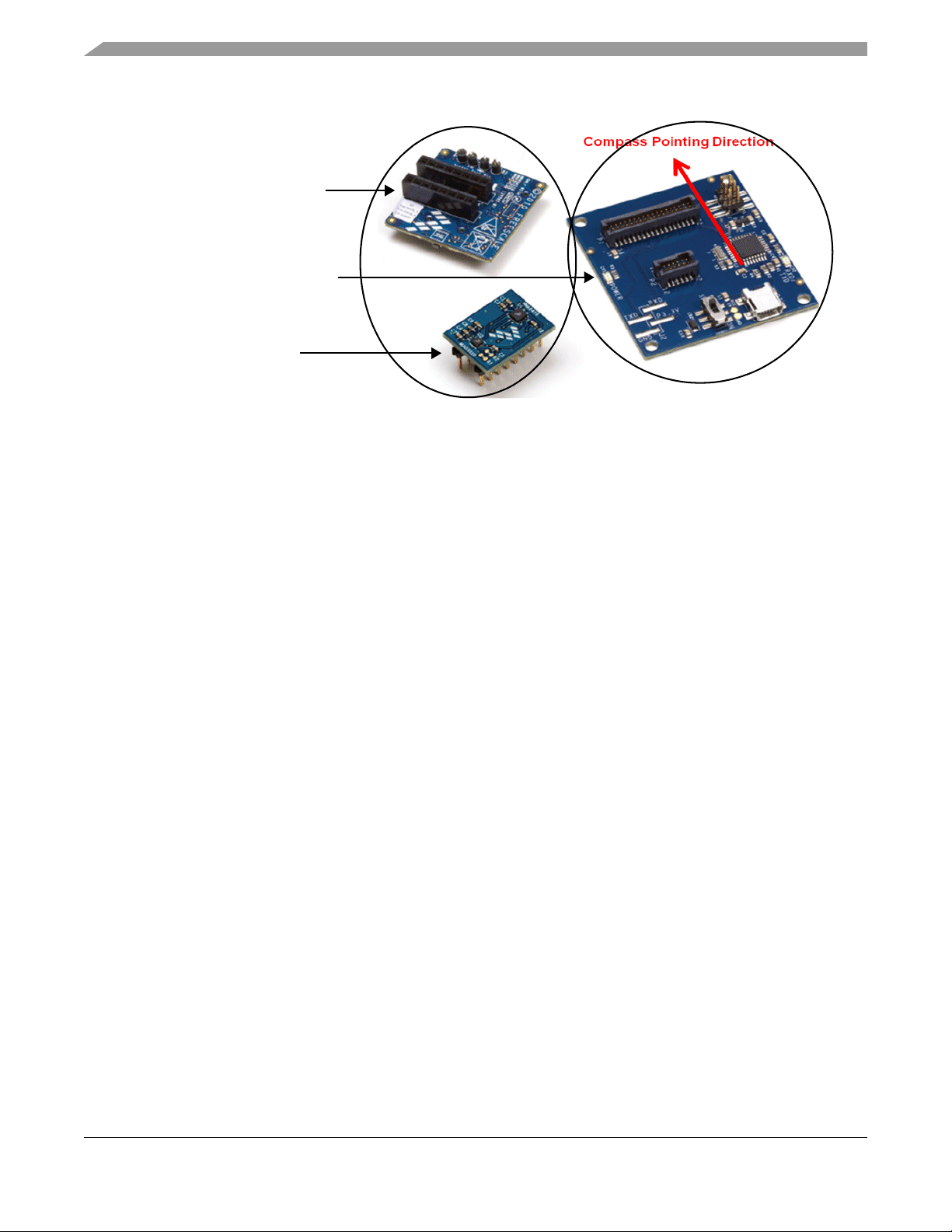
LFSTBEB3110 adapter board
LFSTBUSB USB-interface board
LFSTBEB3110 sensor board with
MAG311 0 and MMA8451Q
LFSTBEB31 10
LFSTBUSB
2 Getting Started
To begin using the kit, assemble the kit’s hardware and install the sensor toolbox software on the
Windows® PC to which the kit will be connected.
2.1 Assembling the Kit
As instructed in the LFSTBEB3110 Quick Start Guide:
1. Attach the two LFSTBEB3110 boards to the LFSTBUSB USB-interface board.
2. The two LFSTBEB3110 boards are supplied connected. If they become separated, reconnect them,
aligning the Pin-1 white arrows on both boards.
The hardware assembly will be completed as part of the software-installation procedure that follows.
When the kit is assembled, its compass-pointing direction is indicated by the red arrow in the preceding
illustration. This direction ergonomically facilitates the evaluation of the eCompass functionality as the
board assembly can be held by its USB connector.
2.2 Installing the Sensor Toolbox Software
The free sensor toolbox software provides an eCompass application with hard- and soft-iron calibration
algorithms.
At the end of the installation process, you will be asked about installing a Future Technology Devices
International (FTDI) serial-to-USB communications driver. This driver is required for communication
between the PC and the evaluation board. If you have previously installed the sensor toolbox software, this
driver already is installed.
The kit’s navigation application uses a Google Maps™ demonstration powered by the Adobe®
Shockwave® software. If the free Shockwave software is not installed on your PC, follow the instructions
at the end of the procedure.
2 Freescale Semiconductor
RD4247MAG3110 Sensor Toolbox Tilt-Compensated eCompass Kit User’s Guide, Rev. 2
Page 3

To install the toolbox software:
1. Download the sensor toolbox software by clicking the following link:
http://www.freescale.com/sensortoolbox.
The webpage, shown below, appears.
Getting Started
2. Click the Download Software button.
The Sensor Toolbox Installer license agreement page appears.
3. Scroll down to the bottom of the page, shown below, and click the I Accept button.
4. Save the software’s installation executable file (SensorToolboxInstaller.exe) to your PC.
5. Complete the kit’ s hardware assembly by using the supplied USB cable to connect the LFSTBUSB
USB-interface board to a USB port on your PC.
If the evaluation board’ s red power LED does not illuminate, check the power switch located next
to the board’s USB connector.
6. Locate the software toolkit’s installation file on your PC and double-click on it.
RD4247MAG3110 Sensor Toolbox Tilt-Compensated eCompass Kit User’s Guide, Rev. 2
Freescale Semiconductor 3
Page 4
Getting Started
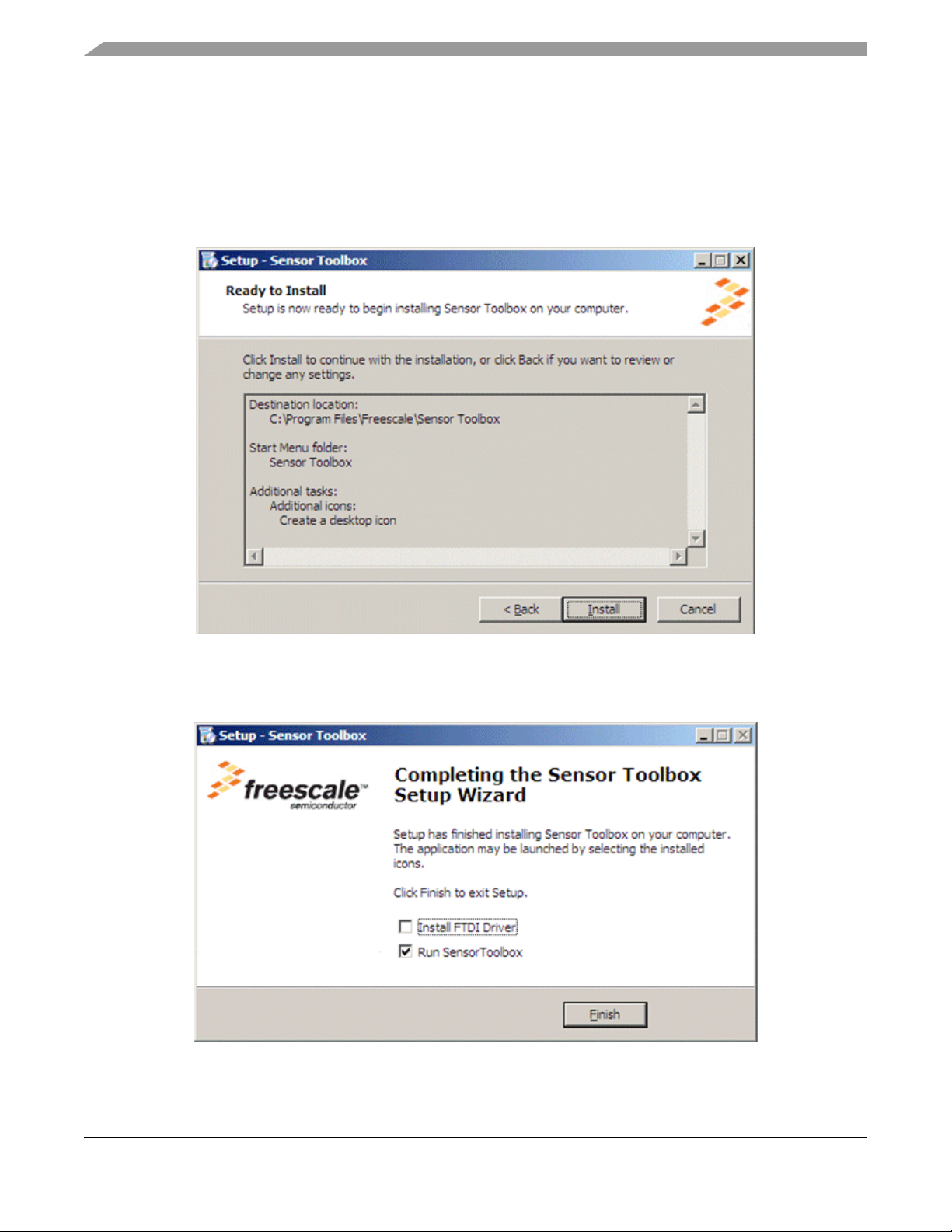
7. Proceed through the setup wizard’s series of dialog boxes.
During the process, you will be asked if you want a Sensor T oolbox icon added to your S tart menu
and desktop.
8. When the Ready to Install dialog box, shown below , appears, review the installation configuration
and click the Install button.
A progress bar displays the status of the software installation and the final dialog box, shown
below, appears.
RD4247MAG3110 Sensor Toolbox Tilt-Compensated eCompass Kit User’s Guide, Rev. 2
4 Freescale Semiconductor
Page 5

Getting Started
9. Do any of the following and click the Finish button:
— To install the Future Technology Devices International (FTDI) serial-to-USB communications
driver, enable the Install FTDI Driver checkbox
— To launch the toolbox software upon completion of the setup, leave the Run Sensor Toolbox
checkbox enabled
If you chose to install the FTDI driver, a command-line window briefly appears.
10. If you do not have the Adobe Shockwave software installed on your PC, use the following link to
download and install that application:
http://get.adobe.com/shockwave/
The application is now ready for use. If you left the Run Sensor T oolbox checkbox enabled, the application
launches and detects the devices connected to the evaluation board. (See the next section.)
RD4247MAG3110 Sensor Toolbox Tilt-Compensated eCompass Kit User’s Guide, Rev. 2
Freescale Semiconductor 5
Page 6
Getting Started
2.3 Launching the Sensor Toolbox Software
1. Ensure that the compass boards are connected to a USB port on your PC with the USB cable.
The evaluation board’s red power LED illuminates. (If the LED does not illuminate, check the
power switch located next to the board’s USB connector.)
2. Launch the toolbox software by doing either of the following:
— Double-click on the application’s desktop icon
— Select Start > Programs > Sensor Toolbox > Sensor Toolbox
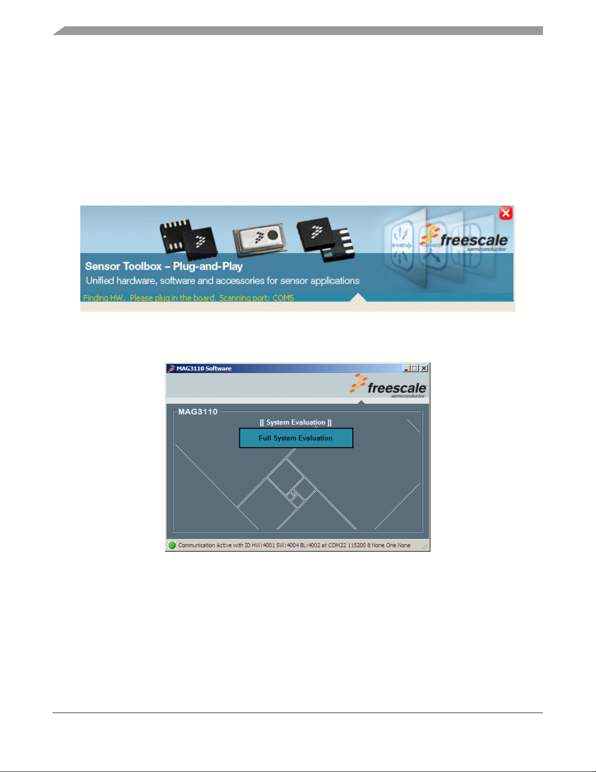
The sensor toolbox’s hardware-detection dialog box, shown below, displays.
Then the MAG3110 evaluation software’s main menu, shown in the following figure, displays.
3. Open the tilt-compensated eCompass application by clicking on Full System Evaluation.
RD4247MAG3110 Sensor Toolbox Tilt-Compensated eCompass Kit User’s Guide, Rev. 2
6 Freescale Semiconductor
Page 7
Quick-Start Demonstration
3 Quick-Start Demonstration
The following demonstration procedure familiarizes you with the Main and Configuration screens and the
calibration functionality.
1. Launch the sensor toolbox software by using the procedure in Section 2.3, “Launching the Sensor
Toolbox Software,” on page 6.
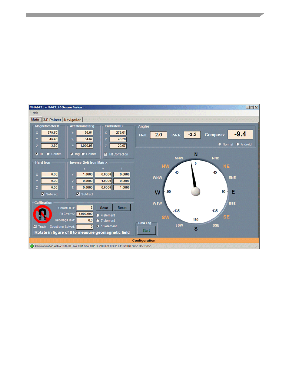
The main eCompass screen appears with a red magnet warning icon in the Calibration frame,
indicating that the compass is out of calibration. Text at the bottom of the frame advises Rotate in
figure of 8 to measure geomagnetic field.
2. Rotate the device in a figure-eight motion as advised.
When a minimum of 16 magnetic measurements are stored in the Smart FIFO, the compass
software uses those measurements to calibrate the device. The default, 10-element calibration is
composed of:
— Three elements in the Hard Iron frame
— Six elements in the Inverse Soft Iron Matrix frame (There are not nine elements because the
matrix is symmetrical.)
— The geomagnetic field strength in the Calibration frame
RD4247MAG3110 Sensor Toolbox Tilt-Compensated eCompass Kit User’s Guide, Rev. 2
Freescale Semiconductor 7
Page 8

Quick-Start Demonstration
When the device is successfully calibrated, as shown in the following figure, the Calibrated frame
displays:
— A Fit Error % that should be less than 2%
— Five green bars, where the red-magnet icon had appeared
— The message Calibrated, at the bottom of the frame
3. Take one of the following actions with the established calibration:
— To freeze the current calibration, clear the Track checkbox
— To update the calibration continuously, enable the Track checkbox
4. Review the readings in the Magnetometer B, Accelerometer g, and Calibrated B frames, shown in
the following figure, that are located in the top, left corner of the Main screen.
— The Magnetometer B frame shows the three com ponents of the magnetic field in µT measured
by the magnetometer sensor
— The Accelerometer g frame shows the three components of the accelerometer sensor output
measured in mg
— The Calibrated B frame shows the magnetometer output corrected by the magnetic calibration
and corrected for the tilt of the evaluation board
RD4247MAG3110 Sensor Toolbox Tilt-Compensated eCompass Kit User’s Guide, Rev. 2
8 Freescale Semiconductor
Page 9

Quick-Start Demonstration
5. If desired, modify the display of the fields in those frames by doing any of the following:
— T o switch the magnetometer’ s display of the magnetic field from the default of µT to bit counts,
select the Counts option
— To switch the accelerometer’s display from the default of mg to bit counts, select the Counts
option
6. Review the Angles frame of the Main screen, shown in the following figure.
— The computed Roll, Pitch and Compass angles and displayed in degrees at the top of the frame
— The Compass angle also is displayed graphically
— The Normal and Android option buttons implement the default and Android standards for
calculating roll and pitch angles
7. Return to the Hard Iron and Inverse Soft Iron Matrix frames in the middle, left portion of the Main
screen and do the following to demonstrate the importance of an accurate magnetic calibration:
RD4247MAG3110 Sensor Toolbox Tilt-Compensated eCompass Kit User’s Guide, Rev. 2
Freescale Semiconductor 9
Page 10

Quick-Start Demonstration
Subtract checkboxes
Tilt Correction checkbox
Fit Error % reading
Element calibration options
— Deselect the Subtract checkboxes in both frames to turn off the hard-iron and soft-iron
corrections for the eCompass and observe how the compass heading becomes jammed.
— Select both Subtract checkboxes to reactivate the calibration corrections and watch the
eCompass become unjammed again.
8. Demonstrate the importance of tilt-compensation algorithms by returning to the Calibrated B
frame, near the top, center of the Main screen, and deselecting the Tilt Correction checkbox to turn
off tilt correction for the eCompass.
The eCompass will still operate if it is held flat, but pitching or rolling the device will cause
dramatic compass heading errors.
9. Examine calibration options by doing the following in the Calibration frame in the bottom, left of
the Main screen:
— Sequentially select the 10 element, 7 element, and 4 element option buttons.
RD4247MAG3110 Sensor Toolbox Tilt-Compensated eCompass Kit User’s Guide, Rev. 2
10 Freescale Semiconductor
Page 11

Quick-Start Demonstration
— Observe how the Fit Error % field’s values increases, in going from the 10-element model to
the 4-element model, as a less-complete calibration model is used.
The 7-element model simplifies the inverse soft-iron matrix to a diagonal matrix with zero
off-diagonal elements. The calibration parameters are the three hard-iron coefficients, the three
soft-iron matrix coefficients, and the geomagnetic field strength.
The 4-element model further simplifies the inverse soft iron matrix simplifies to a unit matrix. The
calibration parameters are the three hard-iron coefficients and the geomagnetic field strength.
10. Deliberately jam the eCompass by bringing it close to a spurious magnetic field (such as a
notebook hard disc or a magnet from a desktop-telephone speaker).
— The Fit Error % field’ s value increases and the number of green calibration bars drops from four
to one and are replaced by the red magnetic warning icon, as shown in the following figure.
— The frame’s status field displays Jammed. Rotate to re-measure geomagnetic field.
11. To unjam the eCompass, do either of the following:
— Move the eCompass away from the jamming source and rotate the evaluation board to obtain
new measurements of the geomagnetic field for calibration.
The Fit Error % value decreases and the number of green bars increases up to five, as the
jammed calibration measurements are replaced by newer measurements.
— Click the Reset button to immediately discard all calibrations and rotate the evaluation board
to capture new calibration data.
RD4247MAG3110 Sensor Toolbox Tilt-Compensated eCompass Kit User’s Guide, Rev. 2
Freescale Semiconductor 11
Page 12

Advanced eCompass Features
4 Advanced eCompass Features
This section looks at advanced configuration and calibration features.
4.1 Configuration Screen
The Calibration screen enables advanced users to change run-time parameters. T o display the screen, move
the mouse pointer over the Configuration bar at the bottom of the Main screen.
The screen’s features are explained in the following table.
RD4247MAG3110 Sensor Toolbox Tilt-Compensated eCompass Kit User’s Guide, Rev. 2
12 Freescale Semiconductor
Page 13

Table 1 Configuration Frame
Screen frame Description
Aligns the magnetometer package to the x, y,
and z axes of the evaluation board in multiples
Magnetometer
1
and Gain
HAL
Accelerometer
1
and Gain
HAL
Low-Pass Filters
of 90 degrees. Pe rmitted values are -1, 0, and
1. The magnetometer reading used by the
eCompass algorithms is obtained by
multiplying the raw magnetometer
measurement by this three-by-three matrix.
These Hardware Abstractio n Layer settings should be
changed only if the sensor toolbox software is being
used with a customer evaluation board whose sensor
Aligns the accelerometer package to the x, y,
and z axes of the evaluation board in multiples
package orientation does not match that of the
MAG3110 and MMA8451Q daughter board.
of 90 degrees. Pe rmitted values are -1, 0, and
1. The accelerometer reading used by the
eCompass algorithms is obtained by
multiplying the raw magnetometer
measurement by this three-by-three matrix.
The Angles LPF (samples) list-box field sets the 1/e time constant (in samples) of the single-pole,
exponential low-pass filters acting on the roll, pitch, and compass heading angles.
The default setting is 16 samples which equates to 0.4s 1/e convergence at the default, 40-Hz sampling
frequency.
Advanced eCompass Features
Sampling Rate
Calibration
Settings
Selects the magnetometer’s output data rates and over-sampling ratios.
The default rate is 40 Hz. For more details on these settings, see the MAG3110 3-Axis, Digital
Magnetometer Data Sheet (MAG3110).
Enables configuration of four parameters used for magnetic calibration.
Configures the data structure that calibrates the device by storing measurements
of the geomagnetic field at different orientations.
Smart FIFO
The default setting is 3x Pitch times 6x Roll times 6x Y a w ranges to give a total of
108 entries. The alternative setting is 4x Pitch times 8x Roll times 8x Y a w values
for a total of 256 entries.
Selects whether the calibration algorithms execute every 10, 20, 40, 80, 120, or
Calibration Interval
160 samples.
At the default sampling rate of 40 Hz, this corresponds to a calibration every 0.25,
0.5, 1, 2, 3, or 4 seconds.
Defines the minimum number of measurements stored in the Smart FIFO to be
used for calibration.
Min Equations
The default setting is 16 measurements with the alternatives of 10, 12, and 14.
The lowest setting is 10 because it is impossible for the 10-element calibration
model to be solved when fewer than 10 measurement equations are available.
Defines the maximum number of measurements stored in the Smart FIFO to be
used for calibration.
The default setting is 64, but this can be set as high as 256. Generally, more
Max Equations
measurements are better, but at the e xpense of increased processing and power
consumption.
If this field is set to 128, 192 or 256, the Smart FIFO field should be set to its larger
value because the smaller value contains only 108 entries which limits
measurements to that number.
Reset Resets the Configuration screen settings to default values.
RD4247MAG3110 Sensor Toolbox Tilt-Compensated eCompass Kit User’s Guide, Rev. 2
Freescale Semiconductor 13
Page 14

Advanced eCompass Features
1
HAL: Hardware Abstraction Layer
To observe the effects of your calibrations, roll the mouse off of the Configuration frame to close it and
display all of the Main screen. Look at the Calibration frame in the bottom, left corner of the screen.
• The Smart FIFO value shows the number of measurements currently stored in the Smart FIFO.
• The Equations Solved value shows the number of measurements equations currently being used
for the solution.
• The Equations Solved value will remain at zero until the Min Equations measurements (set in the
Configuration screen’s Calibration frame) are available for use. The value then will jump to the
Min Equations setting and increase up to the value set for Max Equations.
4.2 Calibration Save
The Calibration frame’s Save button enables advanced users to analyze and visualize the magnetic
calibration by saving the calibration to a tab-delimited ASCII text file that can be opened with a text or
spreadsheet application.
When the button is clicked, a Save As dialog box, shown in the following figure, prompts the user a
filename and storage location for the calibration file.
RD4247MAG3110 Sensor Toolbox Tilt-Compensated eCompass Kit User’s Guide, Rev. 2
14 Freescale Semiconductor
Page 15

Advanced eCompass Features
A sample calibration file follows, with inserted annotations displayed in italic text.
The Smart FIFO has dimensions 3x6x6 for 108 entries in total.
Total assigned smart FIFO size 108
FIFO Roll Phi dimension 6
FIFO Pitch Theta dimension 3
FIFO Yaw Psi dimension 6
The calibration has been computed for the 10 element model.
Number of calibration parameters 10
The hard-iron calibration vector in µT.
Hard iron Vx (uT) 260.3826
Hard iron Vy (uT) 41.64858
Hard iron Vz (uT) -52.42494
The inverse soft-iron matrix.
Inverse Soft Iron invW[0][] 0.9679827 -0.03510316 0.004310295
Inverse Soft Iron invW[1][] -0.03510318 1.015078 0.03668828
Inverse Soft Iron invW[2][] 0.004310329 0.03668828 1.020367
The ellipsoid fit matrix equal to the square of the inverse soft-iron matrix.
Ellipsoid matrix A[0][] 0.9382414 -0.06945354 0.007282599
Ellipsoid matrix A[1][] -0.06945354 1.032962 0.07452545
Ellipsoid matrix A[2][] 0.007282599 0.07452545 1.042513
RD4247MAG3110 Sensor Toolbox Tilt-Compensated eCompass Kit User’s Guide, Rev. 2
Freescale Semiconductor 15
Page 16

Advanced eCompass Features
The fitted geomagnetic field strength in µT.
Geomagnetic field B (uT) 52.31701
The calibration Fit Error in %.
Calibration fit error % 0.7030118
The number of measurement equations used for this calibration.
Measurements used in solution 49
The sample number index of the earliest magnetometer reading used for the calibration.
Earliest sample index used -1
The number of measurements stored in the Smart FIFO.
Smart FIFO count 49
The actual magnetometer measurements stored in the Smart FIFO.
Sample index Bpx (uT) Bpy (uT) Bpz (uT)
80 304.5 16.9 -37.6
13 245.7 -6.4 -33.8
92 298.3 15.5 -73.2
93 300.2 13.6 -66
78 299 21 -23.1
...68 219.9 42.1 -17.9
RD4247MAG3110 Sensor Toolbox Tilt-Compensated eCompass Kit User’s Guide, Rev. 2
16 Freescale Semiconductor
Page 17

Advanced eCompass Features
The text after this line can be pasted into Wolfram Mathematica to display the raw and calibrated data:
Mathematica visualization script
rawdata={
{304.5,16.9,-37.6},
{245.7,-6.4,-33.8},
{298.3,15.5,-73.2},
{300.2,13.6,-66},
...
{219.9,42.1,-17.9}}
caldata={
{43.63754,-26.1265,14.40905},
{-12.44556,-47.57435,17.17816},
{37.53175,-28.63608,-21.9941},
{39.46864,-30.36727,-14.70897},
...
{-39.05349,3.145957,35.07017}}
plot1 = ListPointPlot3D[rawdata, AxesLabel -> {Bx, By, Bz}, Axes -> True, BaseStyle -> {FontSize
-> 14}, BoxRatios -> Automatic, PlotStyle -> Directive[Red, PointSize[0.02]]]
a={{0.9382414,-0.06945354,0.007282599},
{-0.06945354,1.032962,0.07452545},
{0.007282599,0.07452545,1.042513}}
plot2=RegionPlot3D[{x-(260.3826),y-(41.64858),z-(-52.42494)}.a.
{x-(260.3826),y-(41.64858),z-(-52.42494)}<2737.07,
{x,260.3826-120,260.3826+120}, {y,41.64858-120,41.64858+120},
{z,-52.42494-120,-52.42494+120},
PlotPoints -> 100, Mesh -> None, AxesLabel -> {Bx, By, Bz}, BaseStyle -> {FontSize -> 14},
AxesLabel -> Automatic, PlotStyle -> Opacity[0.5]]
plot3 = ListPointPlot3D[caldata, AxesLabel -> {Bx, By, Bz}, Axes -> True, BaseStyle -> {FontSize
-> 14}, BoxRatios -> Automatic, PlotStyle -> Directive[Blue, PointSize[0.02]]]
plot4=RegionPlot3D[x*x+y*y+z*z<2737.07, {x,-100,100}, {y,-100,100}, {z,-100,100},
PlotPoints -> 100, Mesh -> None, AxesLabel -> {Bx, By, Bz}, BaseStyle -> {FontSize -> 14},
AxesLabel -> Automatic, PlotStyle -> Opacity[0.5]]
Show[plot1, plot2, PlotRange -> Automatic]
Show[plot3, plot4, PlotRange -> Automatic]
Show[plot2, plot4, PlotRange -> Automatic]
Show[plot1, plot2, plot3, plot4, PlotRange -> Automatic]
RD4247MAG3110 Sensor Toolbox Tilt-Compensated eCompass Kit User’s Guide, Rev. 2
Freescale Semiconductor 17
Page 18

Advanced eCompass Features
B
x
B
y
B
z
Calibrated magnetic data
Raw magnetic data
A typical mathematical plot is shown in the following figure. The raw magnetic data is shown in red and
shows strong hard- and soft-iron distortions. The calibrated magnetic data is shown in blue and lies on the
surface of a sphere, centered at the origin.
18 Freescale Semiconductor
RD4247MAG3110 Sensor Toolbox Tilt-Compensated eCompass Kit User’s Guide, Rev. 2
Page 19

Advanced eCompass Features
Start / Stop button
4.3 Data Log
The Data Log frame, in the bottom center of the Main screen contains a Start / Stop button, as shown in
the following figure. That button enables or disables, respectively, the logging of sensor data to a file on
the PC’s hard disc.
When the Start button is clicked, the user is prompted for the output filename and location. Because the
file is written in the ASCII format, a .txt filename extension should be used. The data is written at a fixed
rate of 10 Hz, irrespective of the sampling rate selected for the eCompass.
The file format is below. The column headings after T ime S tamp match th e data fields in th e main screen.
The columns and example data are as follows:
Time when this line was recorded and written.
Time 09/08/2011 10:40
Sample number incrementing every 1/40s for the default, 40-Hz sample rate.
Sample index 38151
The x, y and z raw magnetic field values in µT.
Bpx (uT) 290.2
Bpy (uT) 57.9
Bpz (uT) -6.8
The x, y and z raw accelerometer values in mg.
Gpx (mg) 123.54
Gpy (mg) 111.82
Gpz (mg) 987.31
The calibrated and tilt-compensated magnetometer readings.
Bpx (comp, uT) 23.22
Bpy (comp, uT) 6.78
Bpz (comp, uT) 48.6
RD4247MAG3110 Sensor Toolbox Tilt-Compensated eCompass Kit User’s Guide, Rev. 2
Freescale Semiconductor 19
Page 20

3D Pointer Screen
The pitch, roll and yaw/Compass angles in degrees.
Roll (deg) 6.5
Pitch (deg) -7.1
Yaw Compass (deg) -15.7
5 3D Pointer Screen
The 3D Pointer screen uses the sensor daughter board to control of the PC mouse pointer . First ensure that
the compass is calibrated. To start the demonstration, click the Start/Stop button. The compass (yaw) and
pitch angles are used to position the mouse pointer horizontally and vertically, respectively.
To stop the demonstration, manipulate the sensor daughter board to position the mouse pointer over the
Start/Stop button and click the PC mouse.
RD4247MAG3110 Sensor Toolbox Tilt-Compensated eCompass Kit User’s Guide, Rev. 2
20 Freescale Semiconductor
Page 21

6 Navigation Screen
Navigation Screen
The Navigation screen uses all three angles output from the sensor daughter board to control the Google
Maps display. The roll angle controls the display in the left and right direction. The pitch angle controls
the display in forward and backward direction. The compass/yaw angle controls the rotation of the map
display.
The PC must be connected to the internet for this demonstration and the Adobe Shockwave software must
be installed. If Adobe Shockwave is not installed, please follow the instructions at:
http://get.adobe.com/shockwave/
RD4247MAG3110 Sensor Toolbox Tilt-Compensated eCompass Kit User’s Guide, Rev. 2
Freescale Semiconductor 21
Page 22

How to Reach Us:
Home Page:
www.freescale.com
Web Support:
http://www.freescale.com/support
USA/Europe or Locations Not Listed:
Freescale Semiconductor, Inc.
Technical Information Center, EL516
2100 East Elliot Road
Tempe, Arizona 85284
1-800-521-6274 or +1-480-768-2130
www.freescale.com/support
Europe, Middle East, and Africa:
Freescale Halbleiter Deutschland GmbH
Technical Information Center
Schatzbogen 7
81829 Muenchen, Germany
+44 1296 380 456 (English)
+46 8 52200080 (English)
+49 89 92103 559 (German)
+33 1 69 35 48 48 (French)
www.freescale.com/support
Japan:
Freescale Semiconductor Japan Ltd.
Headquarters
ARCO Tower 15F
1-8-1, Shimo-Meguro, Meguro-ku,
Tokyo 153-0064
Japan
0120 191014 or +81 3 5437 9125
support.japan@freescale.com
Asia/Pacific:
Freescale Semiconductor China Ltd.
Exchange Building 23F
No. 118 Jianguo Road
Chaoyang District
Beijing 100022
China
+86 10 5879 8000
support.asia@freescale.com
For Literature Requests Only:
Freescale Semiconductor Literature Distribution Center
1-800-441-2447 or +1-303-675-2140
Fax: +1-303-675-2150
LDCForFreescaleSemiconductor@hibbertgroup.com
Information in this document is provided solely to enable system and software
implementers to use Freescale Semiconductor products. There are no express or
implied copyright licenses granted hereunder to design or fabricate any integrated
circuits or integrated circuits based on the information in this document.
Freescale Semiconductor reserves the right to make changes without further notice to
any products herein. Freescale Semiconductor makes no warranty, representation or
guarantee regarding the suitability of its product s for any particular purpose, nor does
Freescale Semiconductor assume any liability arising out of the application or use of any
product or circuit, and specifically disclaims any and all liability, including without
limitation consequential or incidental damages. “Typical” paramet ers that may be
provided in Freescale Semiconductor data sheet s and/or specifications can and do vary
in different applications and actual performance may vary over time. All operating
parameters, including “Typicals”, must be validated for each customer application by
customer’s technical experts. Freescale Semiconductor does not convey any license
under its patent rights nor the rights of others. Freescale Semiconductor products are
not designed, intended, or authorized for use as components in systems intended for
surgical implant into the body, or other applications intended to support or sustain life,
or for any other application in which the failure of the Freescale Semiconductor prod uct
could create a situation where personal injury or death may occur. Should Buyer
purchase or use Freescale Semiconductor products for any such unintended or
unauthorized application, Buyer shall indemnify and hold Freescale S emiconductor and
its officers, employees, subsidiaries, affiliates, and distributors harmless against all
claims, costs, damages, and expenses, and reasonable attorney fees arising out of,
directly or indirectly, any claim of personal injury or death associated with such
unintended or unauthorized use, even if such claim alleges that Freescale
Semiconductor was negligent regarding the design or manufacture of the part.
Freescale and the Freescale logo are trademarks of Freescale Semiconductor, Inc.,
Reg. U.S. Pat. & Tm. Off. Xtrinsic is a trademark of Freescale Semiconductor, Inc.
All other product or service names are the property of their respective owners.
© 2011 Freescale Semiconductor, Inc. All rights reserved.
RoHS-compliant and/or Pb-free versions of Freescale products have the functionality
and electrical characteristics as their non-RoHS-compliant and/or non-Pb-free
counterparts. For further information, see http://www.freescale.com or contact your
Freescale sales representative.
For information on Freescale’s Environmental Products prog ram, go to
http://www.freescale.com/epp.
MAG3110UG
Rev. 2
08/2011
 Loading...