

Page 1

Freescale Semiconductor
User’s Guide
Document Number:
MPC5746REVB176UG
Rev. 1.6, 9/2015
Qorivva MPC5746R-176DS/252DS
Evaluation Board (EVB)
User’s Guide
by: Bill Terry
32-bit Automotive Applications
1 Introduction
This document describes the Qorivva MPC5746R
evaluation board (EVB) for the 176LQFP, the
252MAPBGA, and the 144LQFP packages. The EVB is
targeted at providing a platform for the evaluation and
development of the MPC5746R automotive MCU,
facilitating hardware and software development as well
as debugging. Settings for switches, jumpers, LEDs, and
push-buttons are shown for basic operation of the
prototype version of the EVB.
This document is preliminary and is subject to change
without notice.
2Features
The EVB provides the following primary features listed
below:
• Standalone operation or use with the optional
MPC57XXXMB main board
Contents
1 Introduction . . . . . . . . . . . . . . . . . . . . . . . . . . . . . . . . . . . 1
2 Features . . . . . . . . . . . . . . . . . . . . . . . . . . . . . . . . . . . . . 1
3 Modular concept . . . . . . . . . . . . . . . . . . . . . . . . . . . . . . . 2
4 EVB configuration . . . . . . . . . . . . . . . . . . . . . . . . . . . . . . 3
4.1 Methods of operation. . . . . . . . . . . . . . . . . . . . . . . . 3
4.2 Power source. . . . . . . . . . . . . . . . . . . . . . . . . . . . . . 3
4.3 Clock Configuration Options . . . . . . . . . . . . . . . . . . 5
4.4 Micro Second Channel Connections . . . . . . . . . . . . 5
4.5 ADC Channel Filters . . . . . . . . . . . . . . . . . . . . . . . . 6
4.6 SIPI Interface. . . . . . . . . . . . . . . . . . . . . . . . . . . . . . 7
4.7 JTAG Interface . . . . . . . . . . . . . . . . . . . . . . . . . . . . 8
4.8 I/O Connectivity and Port Routing . . . . . . . . . . . . . . 9
5 Reset switches . . . . . . . . . . . . . . . . . . . . . . . . . . . . . . . 14
6 LEDs . . . . . . . . . . . . . . . . . . . . . . . . . . . . . . . . . . . . . . . 14
7 Test points. . . . . . . . . . . . . . . . . . . . . . . . . . . . . . . . . . . 14
8 EVB Top View . . . . . . . . . . . . . . . . . . . . . . . . . . . . . . . . 16
9 Schematics . . . . . . . . . . . . . . . . . . . . . . . . . . . . . . . . . . 17
10 EVB Errata. . . . . . . . . . . . . . . . . . . . . . . . . . . . . . . . . . . 17
11 Revision history . . . . . . . . . . . . . . . . . . . . . . . . . . . . . . . 17
© Freescale S
emiconductor, Inc., 2015. All rights reserved.
Page 2

Modular concept
• Socketed MPC5746R in 176-pin LQFP package, 144-pin LQFP package, or 252MAPBGA
package
• Power options
— Power supplied via the two interface connectors when using the EVB with the optional
MPC57XXXMMB main board
— Power supplied via terminal block when using the EVB in standalone configuration
• Debug and trace
— debug via JTAG connector
— Trace using internal trace memory
• Clocks
— 20 MHz crystal
— SMA connector for external clock
— Oscillator
• MicroSecond Channel
— SAMTECH connector providing easy connection to microsecond channel pins
• I/O connectivity
— Access to all port pins when using the EVB with the optional MPC57XXXMB main
board— Access to SCI, CAN, LIN, and UART physical interfaces when using the EVB with
optional MPC57XXXMB main board
the
• Switches
— Power-on reset
• LEDs for power indication
• Test points
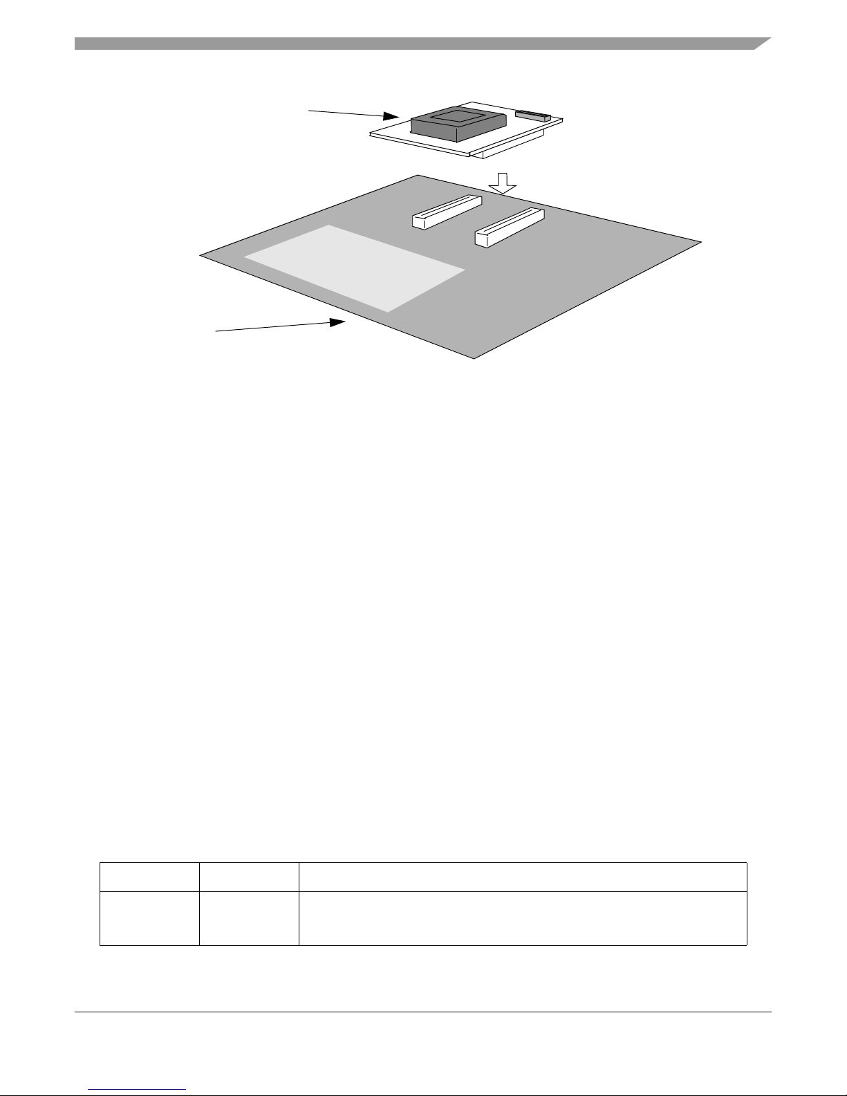
3 Modular concept
The MPC5746R-176DS/252DS/144DS is part of a modular EVB hardware system that consists of:
• A common main board that provides power and access to common communication interfaces and
the MCU I/O port pins. The MPC5746R-176DS/252DS/144DS is compatible with the
MPC57XXXMB main board.
• A package-specific EVB to support all available production package types of the MPC5746R1.
NOTE
The MPC57XXXMB User Guide should be obtained to provide additional
configuration information when used with the MPC5746-xxxDS.
See Figure 1., “MPC5746R EVB and main board system” for an illustration of the modular EVB
hardware system concept.
1.The MPC5746R Emulation Device (ED) requires separate hardware that may be ordered through your Freescale
Salesperson or Representative.
Qorivva MPC5746R-176DS/252DS Evaluation Board (EVB) User’s Guide, Rev. 1.6
Freescale Semiconductor2
Page 3
EVB configuration
MPC5746R-176DS/252DS
MPC57XXXMB
Figure 1. MPC5746R EVB and main board system
4 EVB configuration
This section provides information on how to configure the jumper settings on the EVB. Default settings
are marked as such.
4.1 Methods of operation
Power to the EVB is supplied by one of two options:
1. The MPC57XXXMB main board generates the 5 V/3.3 V/1.25 V supplies and provides these to
the EVB via the interface connectors.
2. In standalone configuration, external 5 V/3.3 V/1.25 V supplies are provided to the EVB via the
terminal block. (This option provides minimal access to I/O)
4.2 Power source
The default jumper settings are configured for using the EVB with the MPC57XXXMB main board.
Power is supplied from the main board to the EVB via the two interface connectors.
The EVB can also operate as a standalone device, where power can be supplied from an external power
source.
Table 1 summarizes the jumper settings for the available power options.
Table 1. Jumper Settings — Power Options
Jumper Setting Description
J23 Choose one:
1-2 ON
2-3 ON
Main IO Voltage Supply - VDD_HV_IO_MAIN
5V supply from motherboard (default)
5V supply from external source
Qorivva MPC5746R-176DS/252DS Evaluation Board (EVB) User’s Guide, Rev. 1.6
Freescale Semiconductor 3
Page 4

EVB configuration
Jumper Setting Description
Table 1. Jumper Settings — Power Options (continued)
J19 Choose one:
1-3 ON
7-9 ON
3-4 ON
7-8 ON
J18 Choose one:
3-5 ON
3-4 ON
1-3 ON
J22 Choose one:
1-2 ON
2-3 ON
J8 Choose one:
1-2 ON
2-3 ON
J3 Choose one:
7-9 ON
1-3 ON
7-8 ON
3-4 ON
J5 Choose one:
7-9 ON
1-3 ON
3-4 ON
7-8 ON
J20 Choose one
7-9 ON
1-3 ON
3-4 ON
7-8 ON
J14 Choose one:
1-2 ON
2-3 ON
J4 Choose one:
7-9 ON
1-3 ON
3-4 ON
7-8 ON
3-5 ON
J17 Choose one:
Installed
Removed
J12 Choose one:
1-2
2-3
Low voltage power select - VDD_LV_SELECT
3.3V mother board supply (default)
5.0V mother board supply
3.3V external supply
5.0V external supply
Low voltage core select - VDD_LV
1.25V external supply 1.25V
internal regulator supply 1.25V
mother board supply (default)
SAR ADC Voltage Supply - VDD_HV_ADV_SAR
5.0V mother board supply (default)
5.0V external supply
SD ADC Voltage Supply - VDD_HV_ADV_SD
5.0V mother board supply (default)
5.0V external supply
High voltage JTAG power - VDD_HV_IO_JTAG
5.0V mother board supply
3.3V mother board supply (default)
5.0V external supply
3.3V external supply
Microsecond Channel I/O Segment Voltage Supply - VDD_HV_IO_MSC
5.0V mother board supply (default)
3.3V mother board supply
3.3V external supply
5.0V external supply
Ethernet I/O Segment Voltage Supply - VDD_HV_IO_FEC
5.0V mother board supply
3.3V mother board supply (default)
3.3V external supply
5.0V external supply
High voltage PMC supply - VDD_HV_PMC
5.0V motherboard supply (default)
5.0V external supply
Standby RAM Supply Input - VDDSTBY
5.0V mother board supply
3.3V mother board supply (default)
3.3V external supply
5.0V external supply
GND (default)
BCTRL - On-chip regulator pass transistor control
Control enabled
Control disabled
Oscillator Power - OSC_PWR
3.3V mother board supply (default)
3.3V external supply
Qorivva MPC5746R-176DS/252DS Evaluation Board (EVB) User’s Guide, Rev. 1.6
Freescale Semiconductor4
Page 5
EVB configuration
If stand alone operation is desired, the following power supplies connections should be made on J6 (see
Table 2). If using the external supplies option, the user should reference the MPC5746R Data Sheet to
ensure that IDD requirements for each supply are met.
Table 2. External power input
J6 Description
Pin 1 1.25 V
Pin 2 3.3 V
Pin 3 5 V
Pin 4 GND
4.3 Clock Configuration Options
The EVB provides three clocking options that are controlled by jumpers:
• On board 20 MHz crystal oscillator
• On board oscillator
• SMA connector for external clock source
Table 3 summarizes the jumper settings for the available clock options. Note that some of these jumpers
are ‘non-populated’ by default and the clock source is configured by default for crystal oscillator
operation.
Table 3. Jumper Settings - Clock Configuration
Jumpers Selected Clock Source
Reference
Designator
JP2 Shunt to terminate EXTAL with 49.9 ohm resistor to GND Remove Remove Install
JP3 Shunt to connect EXTAL to crystal Install Remove Remove
JP4 Shunt to connect EXTAL to oscillator Remove Install Remove
JP5 Shunt to connect EXTAL to SMA connector Remove Remove Install
JP6 Shunt to connect XTAL to GND Remove Install Install
J10 Oscillator enable Remove Install
1
If the oscillator is selected as the clock source, check that J12 (see Table 1) is used to select the desired oscillator power.
Description
Crystal
(default)
Oscillator SMA
1
Remove
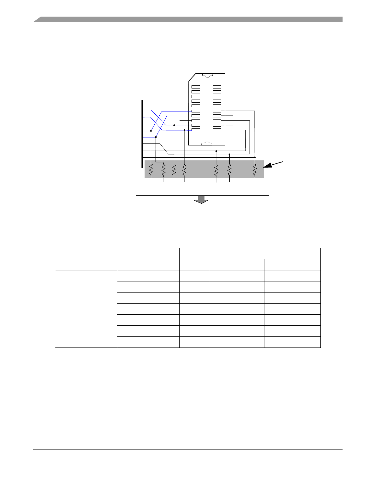
4.4 Micro Second Channel Connections
The microsecond channel signals on MSC1 are grouped at a SAMTECH ERF-8 connector on the EVB to
provide easier user access. This also allows better trace routing of the differential pair signals. The
connections of MSC1 on the connector are shown in Figure 2.
Qorivva MPC5746R-176DS/252DS Evaluation Board (EVB) User’s Guide, Rev. 1.6
Freescale Semiconductor 5
Page 6
EVB co
1
2
19
20
VSS
MSC1_SOUTN PA[ 7]
MSC1_SOUTP PA[ 8]
MSC1_CLKN PA[ 9]
MSC1_CLKP PA[10]
MSC1_RX PA[ 11]
MSC1_CS1 PA[12]
MSC1_CS0 PA[13]
VSS
VSS
VSS
VSS
Motherboard Connector
0
0
0
0
0
0
0
Not populated
R2
R3
R4
R5
R15
R14
R16
nfiguration
Note that by default these signals are not routed to the motherboard via the motherboard interface
connectors. However, zero ohm resistors may be installed at the reference designators listed in Figure 2 if
the signals need to be routed to the motherboard for use as GPIO or other purposes.
Figure 2. Samtech ERF8 - MSC1 Connections (20-pin)
The following table lists the port and pins associated with each of the MSC channel signals.
Table 4. MSC Signal Mapping
Signal Name
Device
Port
Pin Assignment
176LQFP 252MAPBGA
MSC1 MSC1_SOUTN PA7 165 C6
MSC1_SOUTP PA8 164 A6
MSC1_CLKN PA9 161 A7
MSC1_CLKP PA10 160 B7
MSC1_RX PA11 159 C7
MSC1_CS1 PA12 158 B8
MSC1_CS0 PA13 157 A8
4.5 ADC Channel Filters
For convenience, the EVB implements analog RC filters on one differential ADC channel pair, and two
single ended ADC channels. The single ended filter configuration is shown in Figure 3, and the differential
pair filter configuration is shown in Figure 4. The user may modify these component values for the desired
application.
Qorivva MPC5746R-176DS/252DS Evaluation Board (EVB) User’s Guide, Rev. 1.6
Freescale Semiconductor6
Page 7

Figure 3. Single Ended ADC Channel Filters
PZ14
20K
PZ15
20K
0.01μF
0.01μF
C39
0.01μF
C38
0.01μF
C48
C47
J11
1
2
3
4
R19
R21
PY0
20K
PY1
20K
C62
100pF
C61
100pF
J15
1
2
R23
R24
EVB configuration
4.6 SIPI Interface
A SIPI interface is provided on the EVB for high speed interprocessor communications. The SIPI interface
connections are shown in Figure 5 and listed in Table 5.
Freescale Semiconductor 7
Qorivva MPC5746R-176DS/252DS Evaluation Board (EVB) User’s Guide, Rev. 1.6
Figure 4. Differential ADC Channel Filter
Page 8

EVB configuration
Figure 5. SIPI Interface
Table 5. SIPI connector (J1)
Pin Signal Pin Signal
1 SIPI TXP 2 GND
3 SIPI TXN 4 GND
5GND 6SIPI_CLK
7 SIPI RXN 8 GND
9 SIPI RXP 10 GND
4.7 JTAG Interface
A standard JTAG interface is provided on the EVB for debug connections. Note that the Aurora high speed
debug interface is only available with the MPC5746R BD trace adapter board provided as part of the
Freescale calibration solution. The JTAG interface connections are shown in Figure 6 and listed in Table 6.
Qorivva MPC5746R-176DS/252DS Evaluation Board (EVB) User’s Guide, Rev. 1.6
Freescale Semiconductor8
Page 9

Figure 6. JTAG Interface
Table 6. JTAG connector (J7)
EVB configuration
Pin Signal Pin Signal
1TDI 2GND
3TDO 4GND
5TCK 6GND
7 EVTI0 8 PORST_B
9 RESET_B 10 TMS
11 VDD_HV_IO_JTAG 12 GND
13 EVTO0 14 JCOMP
4.8 I/O Connectivity and Port Routing
Most of the MCU’s I/Os are routed to the main mother board. These include the pins associated with the
FlexCAN, Ethernet, and LinFlex interfaces and other normal GPIO pins. The MPC57XXXMB provides
physical layer drivers for these communication protocols. See the MPC57XXXMB User Guide for the
correct jumper settings to enable and configure these drivers and associated circuits.
Table 7 lists the mapping from the MPC5746R device ports to the existing headers/ports on the
MPC57XXXMB motherboard, and to the FlexCAN, Ethernet, UART and LinFlex drivers.
Qorivva MPC5746R-176DS/252DS Evaluation Board (EVB) User’s Guide, Rev. 1.6
Freescale Semiconductor 9
Page 10

EVB configuration
Table 7. Port to Motherboard Mapping — 144LQFP, 176LQFP and 252MAPBGA
MPC5746R Pin Number
Function
Port
144LQFP
176LQFP
252MAPBGA
PA[0] MSC0_CS0 — 142 174 A3
PA[1] MSC0_CS1/SIPI_RXN SIPI_RXN 141 173 B3
PA[2] MSC0_RX/SIPI_RXP SIPI_RXP 140 172 A4
PA[3] MSC0_CLKN — 139 171 B4
PA[4] MSC0_CLKP/SIPI_CLK SIPI_CLK 138 170 C4
PA[5] MSC0_SOUTN/SIPI_TXN SIPI_TXN 137 169 C5
PA[6] MSC0_SOUTP/SIPI_TXP SIPI_TXP 136 168 B5
144LQFP 176LQFP 252MAPBGA
MPC57XXXMB Motherboard
144LQFP
PP[7]
PP[8]
PP[9]
PP[10]
PP[11]
PP[12]
PP[13]
PA[7] n/a MSC1_SOUTN 165 C6 n/a
PA[8] n/a MSC1_SOUTP 164 C7 n/a
PA[9] n/a MSC1_CLKN 161 A6 n/a
PA[10] n/a MSC1_CLKP
160 A7 n/a
PA[11] n/a MSC1_RX 159 B7 n/a
PA[12] n/a MSC1_CS1 158 B8 n/a
PA[13] n/a MSC1_CS0 157 A8 n/a
PB[0] TDO 143 175 D1
PB[1] TDI 144 176 E3
252MAPBGA
2
2
2
2
2
2
2
no connect
no connect
176LQFP
PA[ 0]
no connect
no connect
PA[ 3]
no connect
no connect
no connect
2
PP[7]
2
PP[8]
2
]
PP[9
PP[10]
PP[11]
PP[12]
PP[13]
3
3
1
1
1
1
1
2
2
2
2
PC[0] FEC_REF_CLK 45 56 Y9 PA[15]
PC[1] FEC_TXCLK 46 57 W9 PK[14]
PC[2] FEC_TXEN 47 58 V9 PC[14]
PC[3] FEC_TXD3 48 59 U9 PM[5]
PC[4] FEC_TXD2 49 60 W10 PM[4]
PC[5] FEC_TXD1 50 61 V10 PE[12]
PC[6] FEC_TXD0 51 62 U10 PC[15]
PC[7] FEC_RXD0 54 65 Y11 PC[12]
PC[8] FEC_RXD1 55 66 V11 PC[13]
PC[9] FEC_RXD2 56 67 U11 PM[1]
PC[10] FEC_RXD3 57 68 Y12 PK[15]
PC[11] FEC_RXER 58 69 W12 PM[3]
PC[12] FEC_RXCLK 59 70 V12 PC[10]
PC[13] FEC_RXDV 60 71 U12 PM[0]
PD[0] — 37 45 Y3 PL[0]
PD[1] — 38 46 W3 PL[1]
PD[2] —
PD[3] —
PD[4] —
47 V4 PL[4]
Y4 PL[2]
W4 PL[3]
Qorivva MPC5746R-176DS/252DS Evaluation Board (EVB) User’s Guide, Rev. 1.6
Freescale Semiconductor10
Page 11

EVB configuration
Table 7. Port to Motherboard Mapping — 144LQFP, 176LQFP and 252MAPBGA
MPC5746R Pin Number
Function
Port
PD[5] — Y5 PL[5]
PD[6] —
PD[7] — 39 48 V5 PL[7]
PD[8] FEC_MDC 40 49 V6 PC[3]
PD[9] —
PD[10] —
PD[11] —
PD[12] —
PD[13] FEC_MDIO 43 54 Y8 PC[2]
PD[14] — 44 55 W8 PL[14]
PD[15] —
PE[0] — U8 PE[0]
PF[0] LIN2TX 126 G20 PD[14]
PF[1] LIN2RX
PF[2] LIN3TX
PF[3] LIN3RX
PF[4] CAN0TX
PF[5] CAN0RX
PF[6] CAN1TX
PF[7] CAN1RX
PF[8] —
PF[9] —
PF[10] CAN1TX
PF[11] CAN0RX/CAN1RX 106 130 C20 PF[11]
PF[12] CAN0TX 107 131 C19 PC[9]
PF[13] CAN0RX 108 132 B20 PC[8]
144LQFP
176LQFP
252MAPBGA
144LQFP 176LQFP 252MAPBGA
W5 PL[6]
Y7 PL[9]
52 W7 PL[10]
53 V7 PL[11]
U7 PL[12]
V8 PL[15]
127 G19 PD[15]
G18 PF[2]
G17 PF[3]
F19 PF[4]
D19 PF[5]
E20 PF[6]
E18 PF[7]
D20 PF[8]
D19 PF[9]
D18 PF[10]
MPC57XXXMB Motherboard
144LQFP
252MAPBGA
176LQFP
PG[1] CAN2RX 109 133 A18 PG[14]
PG[2] CAN2TX 110 134 A17 PE[5]
PG[3] —
PG[4] —
PG[5] LIN1RX 111 135 B16 PE[6]
PG[6] LIN1TX 112 136 A16 PE[7]
PG[7] —
PG[9] CAN3RX 113 137 C16 PA[11]
PG[10] —
PG[11] CAN3TX 115 140 B15 PA[10]
PG[12] — 116 141 B14 PG[12]
PG[13] — 117 142 A14 PG[13]
Qorivva MPC5746R-176DS/252DS Evaluation Board (EVB) User’s Guide, Rev. 1.6
Freescale Semiconductor 11
B17 PG[3]
C18 PG[4]
C17 PG[7]
138 A15 PG[10]
Page 12

EVB configuration
Table 7. Port to Motherboard Mapping — 144LQFP, 176LQFP and 252MAPBGA
MPC5746R Pin Number
Function
Port
PG[14] — C15 PE[14]
PG[15] —
PH[0] — 118 143 D14 PH[0]
PH[1] —
PH[2] —
PH[3] — 119 144 C13 PH[3]
PH[4] —
PH[5] —
PH[6] —
PH[7] — 120 145 D12 PH[7]
PH[8] — 121 146 B11 PH[8]
PH[9] —
PH[10] —
PH[11] — 125 150 A10 PH[11]
PH[12] — 126 151 B10 PH[12]
PH[13] —
PH[14] — 127 152 D10 PH[14]
PH[15] — 128 153 A9 PH[15]
144LQFP
176LQFP
252MAPBGA
144LQFP 176LQFP 252MAPBGA
C14 PE[15]
A13 PH[1]
B13 PH[2]
D14 PH[4]
A12 PH[5]
C12 PH[6]
C11 PH[9]
D11 PH[10]
C10 PH[13]
MPC57XXXMB Motherboard
144LQFP
252MAPBGA
176LQFP
PI[0] — 129 154 B9 PI[0]
PI[1] — 130 155 C9 PI[1]
PI[2] —
PI[3] — 131 156 C8 PI[3]
PI[4] —
PI[5] —
PJ[0] — 10 10 H1 PJ[0]
PJ [1] — 11 11 G4 P J[1]
PJ[2] —
PJ[3] —
PJ[4] EVTI_0 12 13 H4
PJ[5] — 17 18 J2 PJ[5]
PJ[6] —
PJ[7] EVTO_0 18 19 J4
PJ[8] — K2 PJ[8]
PJ[9] —
PJ[10] —
PJ[11] — 24 25 L3 PJ[11]
PJ[12] —
PJ[13] —
12 H3 PJ[3]
26 L4 PJ[12]
27 M3 PJ[13]
D9 PI[2]
D8 PI[4]
D7 PI[5]
H2 PJ[2]
no connect
J3 PJ[6]
no connect
K3 PJ[9]
K4 PJ[10]
3
3
Qorivva MPC5746R-176DS/252DS Evaluation Board (EVB) User’s Guide, Rev. 1.6
Freescale Semiconductor12
Page 13

EVB configuration
Table 7. Port to Motherboard Mapping — 144LQFP, 176LQFP and 252MAPBGA
MPC5746R Pin Number
Function
Port
PJ[14] — 25 28 M4 PJ[14]
PJ[15] —
PK[0] — 30 N3 PS[0]
PK[1] — 26 31 N4 PS[1]
PK[2] — 27 32 P1 PS[2]
PK[4] —
PK[5] — 28 34 P3 PS[5]
PK[7] — 31 37 P4 PS[7]
PK[8] — 32 38 R1 PS[8]
PK[9] —
PK[10] — 33 40 T2 PS[10]
PK[11] — 34 41 T3 PS[11]
PK[12] —
PK[13] — 35 43 U2 PS[13]
PK[14] — 36 44 V1 PS[14]
PW[0] — Y13 PW[0]
PW[1] — 64 76 W13 PW[1]
PW[2] —
PW[3] — 63 74 U13 PW[3]
144LQFP
176LQFP
252MAPBGA
144LQFP 176LQFP 252MAPBGA
29 N2 PJ[15]
33 P2 PS[4]
39 R3 PS[9]
42 U1 PS[12]
75 V13 PW[2]
MPC57XXXMB Motherboard
144LQFP
252MAPBGA
176LQFP
PX[0] — U19 PX[0]
PX[1] — 73 89 U18 PX[1]
PX[2] — 72 88 V18 PX[2]
PX[3] — 71 87 Y17 PX[3]
PX[4] —
PX[5] — 68 84 V17 PX[5]
PX[6] —
PX[7] — 67 83 W16 PX[7]
PX[8] —
PX[9] —
PX[10] — 66 81 W15 PX[10]
PX[11] —
PX[12] —
PX[13] —
PX[14] — 65 78 V14 PX[14]
PX[15] —
PY[0] SD2_0 101 N20 n/a
PY[1] SD2_1 80 100 N19
82 Y15 PX[9]
80 Y14 PX[12]
79 W14 PX[13]
77 V16 PX[15]
W17 PX[4]
Y16 PX[6]
U14 PX[8]
V15 PX[11]
no connect
6
no connect
no connect
4
5
Qorivva MPC5746R-176DS/252DS Evaluation Board (EVB) User’s Guide, Rev. 1.6
Freescale Semiconductor 13
Page 14

Reset switches
Table 7. Port to Motherboard Mapping — 144LQFP, 176LQFP and 252MAPBGA
MPC5746R Pin Number
Function
Port
PY[2] — 99 N18 PT[2]
PY[3] —
PY[4] —
PY[5] —
PY[6] — 79 97 P18 PT[6]
PY[7] —
PY[8] —
PY[9] — 78 95 R19 PT[9]
PY[10] —
PY[11] —
PY[12] —
PY[13] — 77 93 T18 PT[13]
PY[14] —
PY[15] — 74 90 V20 PT[15]
PZ[0] — 102 123 H20 PN[0]
PZ[1] — 101 122 H19 PN[1]
PZ[2] — 100 121 H18 PN[2]
PZ[3] — 99 120 H17 PN[3]
PZ[4] — 98 119 J20 PN[4]
PZ[5] — 97 118 J19 PN[5]
PZ[6] — 96 117 J18 PN[6]
PZ[7] — 95 116 J17 PN[7]
PZ[8] — 90 111 K18 PB[0]
PZ[9] — 89 110 K17 PB[1]
PZ[10] — 88 109 L18 PB[2]
PZ[11] — 87 108 L17 PB[3]
PZ[12] — 86 107 M18 PB[4]
PZ[13] — 85 106 M17 PB[5]
PZ[14] — 84 105 M20
PZ[15] — 83 104 M19
1
Routed to Samtech connector 1 on daughter card.
2
Routed to Samtech connector 2 on daughter card and to this port number on MB via a zero ohm resistor..
3
Routed to JTAG connector on daughter card
4
Routed to N side of differential PI-filter on daughter card
5
Routed to P side of differential PI-filter on daughter card
6
Routed to Pi-filter on daughter card
144LQFP
176LQFP
252MAPBGA
144LQFP 176LQFP 252MAPBGA
N17 PT[3]
98 P20 PT[4]
P19 PT[5]
96 P17 PT[7]
R20 PT[8]
94 R18 PT[10]
T20 PT[11]
T19 PT[12]
U20 PT[14]
MPC57XXXMB Motherboard
144LQFP
no connect
no connect
176LQFP
252MAPBGA
5
no connect
4
no connect
6
6
5 Reset switches
The push-button switch SW1 provides a power-on-reset signal to the MCU.
Qorivva MPC5746R-176DS/252DS Evaluation Board (EVB) User’s Guide, Rev. 1.6
Freescale Semiconductor14
Page 15

6LEDs
LEDs shown in Table 8 provide indicators for:
• Power from external 5.0 V supply
• Reset states
Table 8. LEDs
LED Description
D1 5V External Supply
D2 RESET_B
D3 PORST_B
7Test points
Test points shown in Tab le 9 are available to allow probing of various voltages and signals.
Table 9. Test points
LEDs
Test Point Description
TP1 SIPI_CLK
TP2 VDD_HV_MSC
TP3 VDD_STBY
TP4 VDD_HV_IO_JTAG
TP5 SIPI_TXP
TP6 SIPI_TXN
TP7 SIPI_RXN
TP8 SIPI_RXP
TP9 GND
TP10 GND
TP11 VSSA_JTAG
TP12 VDD_HV_ADV_SD
TP13 VSSA_ADC
TP14 VDD_HV_PMC
TP15 VDD_HV_FLA
TP16 VDD_LV_CORE
TP17 GND
TP18 GND
TP19 VDD_HV_IO_FEC
TP20 VDD_HV_ADV_SAR
Qorivva MPC5746R-176DS/252DS Evaluation Board (EVB) User’s Guide, Rev. 1.6
Freescale Semiconductor 15
Page 16

Schematics
Table 9. Test points (continued)
Test Point Description
TP21 VDD_HV_IO_MAIN
8 Schematics
The MPC5746R-176DS, MPC5746R-252DS and MPC5746R-144DS schematics are available as an
attachment in this PDF document. To access the schematic open the bookmark window and click on the
paper clip icon on the left side of the page.
9 EVB Errata
EVB errata are listed in the following table.
Errata List
Affected
Errata Description
176DS 252DS 144DS
Workaround
Port pin PG[9] (CAN3RX) on the MPC5746R was
routed to motherboard port pin PA[13] instead of
PA[11]. PA[11] is also routed on the motherboard to
J38, which is a selectable RX pin for the CAN
1
transceiver. This prevents the CAN RX signal from
being connected directly via motherboard trace to
the PG[9] pin on the MPC5746R for the CAN3RX
function.
Yes No N o
To connect the RX signal from
the CAN bus interface (J6) to the
CAN3RX signal on the
MPC5746R device at pin PG[9],
place a wire jumper from PA[13]
on the motherboard to pin 3 on
J38.
Qorivva MPC5746R-176DS/252DS Evaluation Board (EVB) User’s Guide, Rev. 1.6
Freescale Semiconductor16
Page 17

10 Revision history
Revision number Date Description
1.0 04/24/2013 Initial version.
1.1 04/25/2013 Updated from review comments.
1.2 04/25/2013 Added EVB Errata section and updated
1.3 09/09/2013 Updated Table 7 to include port
1.4 09/11/2013
Revision history
Table 10. Revision history
with current known errata.
mappings from 252MAPBGA pins. Other
minimal modifications to various sections
so that User Guide supports both 176
and 252 packages.
Removed Top View section. Updated
Errata list to included affected DS
1.5 04/23/2014
1.6 09/01/2015 Changed all instances of MPC5746M
Updated Table 7 to include port
mappings from 144LQFP pins. Other
minimal modifications to various sections
so that User Guide supports the 176,
252, an
d 144 packages.
to MPC57XXX.
Qorivva MPC5746R-176DS/252DS Evaluation Board (EVB) User’s Guide, Rev. 1.6
Freescale Semiconductor 17
Page 18

How to Reach Us:
Home Page:
freescale.com
Web Support:
freescale.com/support
Information in this document is provided solely to enable system and software
implementers to use Freescale products. There are no express or implied copyright
licenses granted hereunder to design or fabricate any integrated circuits based on the
information in this document.
Freescale reserves the right to make changes without further notice to any products
herein. Freescale makes no warranty, representation, or guarantee regarding the
suitability of its products for any particular purpose, nor does Freescale assume any
liability arising out of the application or use of any product or circuit, and specifically
disclaims any and all liability, including without limitation consequential or incidental
damages. “Typical” parameters that may be provided in Freescale data sheets and/or
specifications can and do vary in different applications, and actual performance may
vary over time. All operating parameters, including “typicals,” must be validated for
each customer application by customer’s technical experts. Freescale does not convey
any license under its patent rights nor the rights of others. Freescale sells products
pursuant to standard terms and conditions of sale, which can be found at the following
address: http://www.reg.net/v2/webservices/Freescale/Docs/TermsandConditions.htm
Freescale, the Freescale logo, AltiVec, C-5, CodeTest, CodeWarrior, ColdFire,
C-Ware, Energy Efficient Solutions logo, Kinetis, mobileGT, PowerQUICC, Processor
Expert, QorIQ, Qorivva, StarCore, Symphony, and VortiQa are trademarks of
Freescale Semiconductor, Inc., Reg. U.S. Pat. & Tm. Off. Airfast, BeeKit, BeeStack,
ColdFire+, CoreNet, Flexis, MagniV, MXC, Platform in a Package, QorIQ Qonverge,
QUICC Engine, Ready Play, SafeAssure, SMARTMOS, TurboLink, Vybrid, and Xtrinsic
are trademarks of Freescale Semiconductor, Inc. All other product or service names
are the property of their respective owners.
The Power Architecture and
Power.org word marks and the Power and Power.org logos and related
marks are trademarks and service marks licensed by Power.org.
© 2012 Freescale Semiconductor, Inc.
Document Number: MPC5746REVB176UG
Rev. 1.6
9/2015
Page 19

Mouser Electronics
Authorized Distributor
Click to View Pricing, Inventory, Delivery & Lifecycle Information:
NXP:
MPC5746R-252DS MPC5746R-144DS MPC5746R-176DS
 Loading...