

Page 1

Freescale Semiconductor
Getting Started
Document Number: LS1021A-IOTGS
Rev 2, 02/2015
QorIQ LS1021A-IOT Gateway
Reference Design Getting Started
Guide
Contents
1 Introduction
This document explains how to get started with the QorIQ
LS1021A Internet of Things (LS1021A-IOT) reference design
board and verify its basic operations. It also details the
switches, connectors, jumpers, push buttons, and LED
settings, as well as instructions on how to connect the
peripheral devices.
NOTE
It is assumed that you are familiar with the
LS1021A device and the content of the
LS1021A-IOT Reference Manual
(LS1021A-IOTRM).
1 Introduction................................................................1
1.1 Related documentation................................... 2
1.2 Kit contents....................................................2
2 Case and PCB description................... ......................3
3 Initial board startup........................ ...........................6
4 Connecting JTAG connectivity unit.... ..................... 8
5 Configuring switches and jumpers...... ..................... 9
6 Functional status and known
limitations................................................................ 11
7 Revision history.......................... ............................ 13
© 2015 Freescale Semiconductor, Inc.
Page 2

Introduction
1.1 Related documentation
The table below lists and explains the additional documents and resources that you can refer to, for more information on
LS1021A-IOT board.
Some of the documents listed below may be available only under a non-disclosure agreement (NDA). To request access to
these documents, contact your local field applications engineer or sales representative.
Table 1. Related documentation
Document Description
LS1021A QorIQ Advanced Multicore
Processor Data Sheet (LS1021ADS)
LS1021A QorIQ Integrated Multicore
Processor Reference Manual
(LS1021ARM)
The SystemID Format for Power
Architecture™ Development
Systems (AN3638)
LS1021A-IOT Reference Manual
(LS1021A-IOTRM)
Provides information about electrical characteristics, hardware design considerations,
pin assignments, package information, and ordering information.
Provides a detailed description about LS1021A QorIQ multicore processor and its
features, such as memory map, serial interfaces, power supply, chip features, and
clock information.
Freescale Semiconductor Power Architecture™ technology-based evaluation and
development platforms may optionally implement a System ID non-volatile memory
device. This device stores important configuration data about the board.
Provides a detailed description of the architecture, connector pin outs, CPLD system
controller architecture, board configuration and debug support for LS1021A-IOT QorIQ
IOT Reference platform.
1.2 Kit contents
This section illustrates the contents of LS1021A-IOT Gateway box, front and rear elevations, as well as the main features of
the top and bottom side of the LS1021A-IOT Printed Circuit Board (PCB).
The LS1021A-IOT Gateway Reference design board is supplied with the following contents as shown in the figure below.
• 1x LS1021A-IOT Gateway
• 1x 12 V at 5 A PSU
• 1x Micro-B USB cable
• 1x HDMI cable
• 1x 8 GB SDHC card
QorIQ LS1021A-IOT Gateway Reference Design Getting Started Guide, Rev 2, 02/2015
2 Freescale Semiconductor, Inc.
Page 3
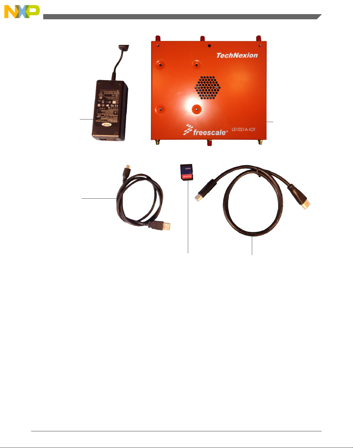
12V@5A Power Supply
Micro B USB Cable
SDHC Card HDMI Cable
LS1021A-IOT Gateway
Case and PCB description
2
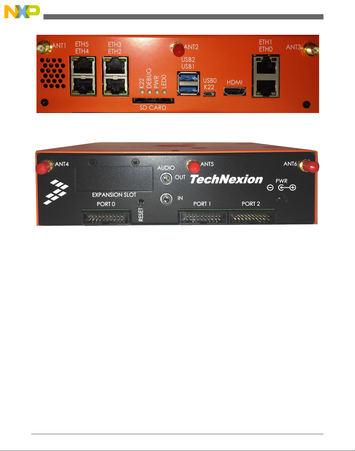
The LS1021A-IOT is contained within an enclosure. The following figures of the front and rear panels are annotated to
describe the I/O functions and indicators.
Freescale Semiconductor, Inc. 3
Figure 1. LS1021A-IOT kit contents
Case and PCB description
QorIQ LS1021A-IOT Gateway Reference Design Getting Started Guide, Rev 2, 02/2015
Page 4
Case and PCB description
Figure 2. Main features - Front chassis
Figure 3. Main features - Rear chassis
The features of the board are shown in the following figures.
QorIQ LS1021A-IOT Gateway Reference Design Getting Started Guide, Rev 2, 02/2015
4 Freescale Semiconductor, Inc.
Page 5
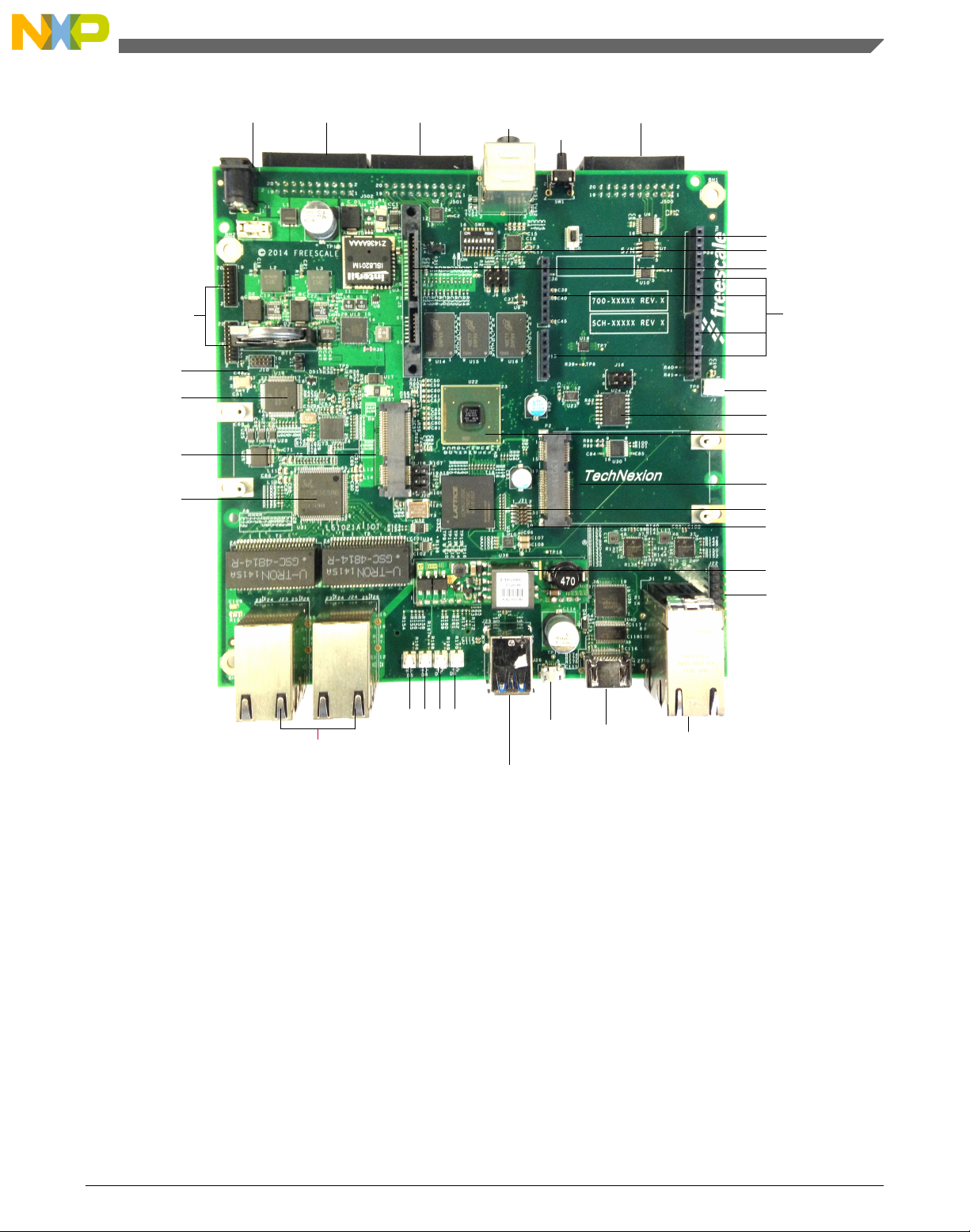
12V POWER PORT2 PORT1
AUDIO
JACKS
RESET
SW1
PORT0
SW3
SW2
SATA
ARDUINO
SHIELD
CONNECTORS
12V FAN HEADER
QSPI FLASH
LS1021A
MPCIE SLOT2
CPLD
LS1 JTAG
PoE Module
CPLD JTAG
2xRJ45 Gigabit
SGMII PORTS
HDMI
USB
SERIAL
/JTAG
2x USB 3.0
TYPE A
4xRJ45 Gigabit
L2 SWITCH PORTS
K22 LED
L2 SWITCH
MPCIE SLOT1
K22
K22 JTAG
K22 EXPANSION
ASLEEP
POWER
K22 LED
Case and PCB description
Figure 4. Main features - Top
QorIQ LS1021A-IOT Gateway Reference Design Getting Started Guide, Rev 2, 02/2015
Freescale Semiconductor, Inc. 5
Page 6

SD CARD SLOT
Initial board startup
Figure 5. Main features - Bottom
Initial board startup
3
QorIQ LS1021A-IOT Gateway Reference Design Getting Started Guide, Rev 2, 02/2015
6 Freescale Semiconductor, Inc.
Page 7

Initial board startup
The LS1021A-IOT board comes with an SDHC card preloaded with the U-Boot and Linux images. Serial connectivity for
the LS1021A-IOT board is provided through the Micro-B USB connector labeled USB0/K22 on the front panel as shown in
Figure 2.
NOTE
You need to install the USB drivers on the host PC before using the serial terminal. You
can download the latest drivers from https://mbed.org/handbook/Windows-serial-
configuration
To start up the board:
1. After installing the drivers, connect the PC with LS1021A-IOT USB0 port using a Micro-B USB cable.
2. Insert the SDHC card into the SD CARD slot located on the front panel of the LS1021A-IOT board. Note that the
SDHC card contacts should be facing up.
3. Set up a serial terminal using a PC communication program such as TeraTerm set to 115200-8-N-1.
4. Select the first COM port assigned to the Virtual MBED COM port.
5. Plug in the power supply barrel into the port labeled PWR located on the rear panel.
6. Plug the power supply into the mains and switch on.
7. Verify the LED PWR and LED0 are lit. LED DEBUG should be off. LED K22 will blink with terminal activity.
8. Check if you can see U-Boot in the terminal window.
U-Boot is configured to automatically load the Linux kernel, device tree, and file system binaries from the SD card to
memory and boot to a Linux prompt. When prompted for a login, type root and press enter. The SDK package used to
build these images is available for download at: http://www.freescale.com/webapp/sps/site/prod_summary.jsp?
code=LS1021A-IoT&fpsp=1amp;tab=Design_Tools_Tab
NOTE
The IOT SDK release 1.3 does not support reading system MAC addresses from
the onboard EEPROM.
If the users wish to change the default MAC address values defined in the U-Boot,
the command format below can be run from the U-Boot command line and
saveenv can be used to maintain the values after a system reset.
ETH0 => setenv ethaddr xx:xx:xx:xx:xx:xx
ETH1 => setenv eth1addr yy:yy:yy:yy:yy:yy
The table below lists all the LED operations.
Table 2. LED operations
Description Ref Color LED On LED Off
K22 MBED status D5 Green MBED mode
LED ON – MBED driver
running
LED Blink – UART/
CMSIS-DAP activity
Bootloader mode
LED BLINK SLOW –
Bootloader running
LED BLINK FAST –
Application image
flashed
MBED driver not loaded
Table continues on the next page...
QorIQ LS1021A-IOT Gateway Reference Design Getting Started Guide, Rev 2, 02/2015
Freescale Semiconductor, Inc. 7
Page 8

Connecting JTAG connectivity unit
Table 2. LED operations (continued)
Description Ref Color LED On LED Off
LS1021A ASLEEP D6 Red ASLEEP Out of asleep
+3V3 D7 Green 3V3 Power ON 3V3 Power OFF
Reset Complete D8 Green Reset Sequence
Completed Successfully
SGMII Ethernet
eTSEC1
SGMII Ethernet
eTSEC3
L2 Switch Ethernet
Port1
L2 Switch Ethernet
Port2
L2 Switch Ethernet
Port3
L2 Switch Ethernet
Port4
ETH0 Green/Orange ON – Link Blink -
Activity
ETH1 Green/Orange ON – Link Blink -
Activity
ETH2 Green/Orange ON – Link Blink -
Activity
ETH3 Green/Orange ON – Link Blink -
Activity
ETH4 Green/Orange ON – Link Blink -
Activity
ETH5 Green/Orange ON – Link Blink -
Activity
Reset not complete
No Link
No Link
No Link
No Link
No Link
No Link
4 Connecting JTAG connectivity unit
JTAG connectivity to the LS1021A on the LS1021A-IOT board is available from two sources:
• CMSIS-DAP via USB0 – the onboard TAP (slower and limited features)
• JTAG Header – Internal 10pin ARM Debug Header – requires a Debugger such as the Freescale CodeWarrior TAP
Both methods require debug software, such as Freescale CodeWarrior to work with the board.
CMSIS-DAP via USB0
NOTE
When USB0 is connected to the host PC via a Micro-B connector, in addition to the
UART bridge functionality, a JTAG bridge is provided. Both can run concurrently.
1. Open the case.
2. Ensure SW2.8 is in the ON position to select CMSIS-DAP operation.
3. Close the lid, if desired.
4. Connect the USB0 to the host PC USB port using Micro-B cable.
5. Switch on the power supply to the board.
6. Check for completion of the reset sequence (ensure the LEDs are as described in Initial board startup).
7. Check the device manager on a Windows machine, to verify that the CMSIS-DAP device is installed correctly.
NOTE
For further information, see the Debugger User Manual.
JTAG Header
1. Ensure the board is not switched on.
2. Open the case.
3. Set SW2.8 in OFF position to select JTAG header operation.
4. Connect the JTAG connectivity unit to the LS1021A JTAG connector J21. Pin 1 is marked on the board.
QorIQ LS1021A-IOT Gateway Reference Design Getting Started Guide, Rev 2, 02/2015
8 Freescale Semiconductor, Inc.
Page 9

SW2[1:8] : OFF OFF OFF OFF OFF ON ON OFF
Configuring switches and jumpers
5. Switch on the power supply to the board.
6. Check for completion of the reset sequence (ensure the LEDs are as described in Initial board startup).
NOTE
For further information, see the Debugger User Manual.
5 Configuring switches and jumpers
The LS1021A-IOT board has one 8-way dual in-line package (DIP) switch. The default DIP switch positions provide
working setup values for the board. Check the default positions and ensure that the board is operational before changing the
switches. The figure below shows the settings for the switches with their default positions.
Figure 6. Default switch configuration
The following table lists and describes the switch configuration for LS1021A-IOT board.
NOTE
The default switch settings are indicated by » symbol.
QorIQ LS1021A-IOT Gateway Reference Design Getting Started Guide, Rev 2, 02/2015
Freescale Semiconductor, Inc. 9
Page 10

Configuring switches and jumpers
Table 3. Default switch settings
Feature Settings (OFF=1,
ON=0)
S2.1 OFF RCW & Boot Source 0 : QSPI (not supported on revA board)
S2.2 OFF SYSCLK Select 0 : DIFF_SYSCLK
S2.3 OFF Reserved 0 : Reserved
S2.4 OFF Reserved 0 : Reserved
S2.5 OFF SGMII2_SATA MUX 0 : SerDes Lane 2 - SATA
S2.[6 :7] ON:ON SYSCLK Frequency Select »00 : 100MHz (default)
S2.8 OFF SDA_SWD_EN Control 0 : K22 CMSIS-DAP
Option Comments
» 1 : SDHC (default)
»1 : SYSCLK (default)
»1 : Reserved (default)
»1 : Reserved (default)
»1 : SerDes Lane 2 – SGMII2 (default)
01 : 99MHz
10 : 96MHz
11: Reserved
»1 : JTAG HEADER (default)
The following table lists the jumper settings.
Table 4. Jumper settings
Jumpers Default settings on LS1021A-IOT Description
J11 OFF VDD_LP Source Select
OFF – Battery
ON - +1V0_VDDC
J18 OFF Reserved
J19 OFF Reserved
J20 OFF Reserved
The following figure shows the jumper locations.
QorIQ LS1021A-IOT Gateway Reference Design Getting Started Guide, Rev 2, 02/2015
10 Freescale Semiconductor, Inc.
Page 11

J11
Functional status and known limitations
Figure 7. Jumper settings
6
Functional status and known limitations
The following table describes the functional status and lists the known limitations.
Table 5. Functional status and known limitations
Interface Functional
JTAG Header Yes
CMSIS-DAP (USB0) Yes
K22 UART (USB0) Yes
Ethernet Switch RJ45
ETH2-5
ETH0 Yes
ETH1 Yes
QorIQ LS1021A-IOT Gateway Reference Design Getting Started Guide, Rev 2, 02/2015
Freescale Semiconductor, Inc. 11
1
Yes
Table continues on the next page...
Page 12

Functional status and known limitations
Table 5. Functional status and known limitations (continued)
SATA See note
MiniPCIe Slot 1 Yes
MiniPCIe Slot 2 Yes
USB1/2 Yes
Accelerometer Yes
Temp Sensor LS1 Yes
Temp Sensor Board Yes
Fan Yes
Current Sensor 12V Yes
Current Sensor 1V VDD Yes
DDR3L Yes
QSPI Boot No
CPLD Yes
UART Yes
LPUART Yes
SPI Yes
I2C1 Yes
I2C2 No - see note
CAN/FTM/GPIO3 expansion See note
SAI Audio See note
HDMI See note
SDHC Yes
ADC Yes
GPIO Expander Yes
EEPROM Yes
Arduino Yes
K22 Expansion No
2
3
4
6
7
8
9
5
1. Requires L2 switch initialisation. This is included as part of the IOT SDK rds build (see SDK README for build details)
2. SATA
• Not supported in the current SDK
• Muxed with SGMII ETH0 (see Table 3 above for details)
3. Some USB flash drives are incompatible (see the SDK release notes for details)
4. Controlled by LS1 temp sensor. The default settings can be modified in the sensors3.conf file within the SDK file
system
5. Common bus with I2C1. See the device errata for details
6. CAN/FTM/GPIO3 expansion
• GPIO functional
• CAN is not supported in current SDK
7. SAI Audio
• Audio output supported (the appropriate kernel options must be enabled)
• Audio Line In is supported (SDK 1.3 requires alsamixer line in to be configured)
8. HDMI
• Limited resolutions supported in the current SDK
• For full VSYNC/HSYNC support, the RCW needs to be updated to enable these signals and UART1 cannot be used.
See the device errata for details
9. Reserved for future use
QorIQ LS1021A-IOT Gateway Reference Design Getting Started Guide, Rev 2, 02/2015
12 Freescale Semiconductor, Inc.
Page 13

7 Revision history
This table summarizes revisions to this document.
Table 6. Revision history
Revision Date Change description
Rev 2 02/2015 Updated all the figures to reflect the changes to the Gateway box and the PCB
Rev 1 01/2015 • Updated section, Initial board startup :
• Added download location for SDK package used to build the images
• Added new note
• Updated Table 3 in section, Configuring switches and jumpers
• Added new topic Functional status and known limitations
Rev 0 09/2014 Initial public release
Revision history
QorIQ LS1021A-IOT Gateway Reference Design Getting Started Guide, Rev 2, 02/2015
Freescale Semiconductor, Inc. 13
Page 14

How to Reach Us:
Home Page:
freescale.com
Web Support:
freescale.com/support
Information in this document is provided solely to enable system and
software implementers to use Freescale products. There are no express
or implied copyright licenses granted hereunder to design or fabricate
any integrated circuits based on the information in this document.
Freescale reserves the right to make changes without further notice to
any products herein.
Freescale makes no warranty, representation, or guarantee regarding
the suitability of its products for any particular purpose, nor does
Freescale assume any liability arising out of the application or use of
any product or circuit, and specifically disclaims any and all liability,
including without limitation consequential or incidental damages.
“Typical” parameters that may be provided in Freescale data sheets
and/or specifications can and do vary in different applications, and
actual performance may vary over time. All operating parameters,
including “typicals,” must be validated for each customer application by
customer's technical experts. Freescale does not convey any license
under its patent rights nor the rights of others. Freescale sells products
pursuant to standard terms and conditions of sale, which can be found
at the following address: freescale.com/SalesTermsandConditions.
Freescale, the Freescale logo, and QorIQ are trademarks of Freescale
Semiconductor, Inc., Reg. U.S. Pat. & Tm. Off. Layerscape and QUICC
Engine are trademarks of Freescale Semiconductor, Inc. All other
product or service names are the property of their respective owners.
ARM, Cortex, and TrustZone are registered trademarks of ARM Limited
(or its subsidiaries) in the EU and/or elsewhere. All rights reserved.
© 2014-2015 Freescale Semiconductor, Inc.
Document Number LS1021A-IOTGS
Revision 2, 02/2015
 Loading...