

Page 1

Freescale Semiconductor
Hardware Getting Started Guide
MSC8156EVM
Document Number: MSC8156EVMHGSG
Rev. 0 10/2010
This document describes the MSC8156EVM and its related
hardware kit. The MSC8156EVM getting started procedure
explains and verifies the board’s basic operation in a
step-by-step format. Settings for switches, jumpers, LEDs,
and push buttons are shown. There are also instructions for
connecting the EVM to your development/debug platform
with CodeWarrior IDE installed.
The MSC8156EVM functions with an integrated
development environment (IDE), such as Freescale
CodeW arrior IDE. Inst ructions for working with the IDE are
beyond the scope of this document.
Contents
1.Definitions, Acronyms, and Abbreviations . . . . . . . . . . . . 2
2.Bit and Byte Conventions . . . . . . . . . . . . . . . . . . . . . . . . . 3
3.Related Reading . . . . . . . . . . . . . . . . . . . . . . . . . . . . . . . . . 3
4.Hardware Kit Contents . . . . . . . . . . . . . . . . . . . . . . . . . . . 4
5.DIP Switch Location Default Settings . . . . . . . . . . . . . . . . 5
6.Power Switch and Push Buttons . . . . . . . . . . . . . . . . . . . . 6
7.Jumper Default Settings . . . . . . . . . . . . . . . . . . . . . . . . . . . 7
8.Connector Default Settings . . . . . . . . . . . . . . . . . . . . . . . . 8
9.LED Indicators . . . . . . . . . . . . . . . . . . . . . . . . . . . . . . . . . . 9
10.Getting Started Procedure . . . . . . . . . . . . . . . . . . . . . . . 10
11.Next Steps . . . . . . . . . . . . . . . . . . . . . . . . . . . . . . . . . . . 11
© 2010 Freescale Semiconductor, Inc.
Page 2

Definitions, Acronyms, and Abbreviations
1 Definitions, Acronyms, an d Abbreviations
Table 1. Definitions, Acronyms, and Abbreviations
Usage Description
EVM Evaluation Module
BP Boot Patch Bit (in RCW)
BPRT Boot Port F ield (in RCW)
CLK SEL Clock Select
CLKIN Clock Input
CLKOUT/CLKO Clock Output
CS Chip Select signal
CTLS Serial RapidIO interface System Mode Bit (in RCW)
DDR Double Data Rate Memory
DEVID Device ID Bit (in RCW)
DIP Dual-in-Line Package (switche s)
EEPROM Electrical Erasable Programmable Memory
EN Enable
EP PCI Express End Point
ETH Ethernet
eUTAP Embedded UTAP
EWDT Watchdog Timer Bit (in RCW)
GE Gigabit Ethernet Port Bit (in RC W)
GE/TDM GETH/TDM Port
GETH Gigabit Ethernet
GPIO General Purpose I/O
HDC Hardcoded Option (RCW Source)
HRESET/HRST Hard Reset
2
I
C Inter-Integrated Circuit Multi-master Serial Computer Bus
IO Input/Output
J/JP Jumper
LD/LED Light-emitting Diode
MAPLE MSC8156 Internal Module
MODCK Clock Mode
NMI Non-Maskable Interrupt
PCB Printed Circuit Board
PCI Peripheral Components Interconnect Bus
PG “Power Good”
PLL Phased Lock Loop
PRDY PCI Express Ready Bit (in RCW)
PRESET Power-on-Reset
RC MSC8156 Internal Module PCI Express Root Complex
RC[x] Reset Configuration Bit x
RCW Reset Configuration Word
RGMII Reduced General Media Independent Interf ac e
RHE RIO Host Bit (in RCW)
RJ45 Ethernet Connectors
SBETH Simple Boot from Ethernet Bit (in RCW)
MSC8156-EVM Hardware Getting Started, Rev. 0
2 Freescale Semiconduct or
Page 3
Table 1. Definitions, Acronyms, and Abbreviations (continued)
Usage Description
SCLK SerDes Reference Clock Bit (in RCW)
SerDes
SODIMM Mini DIMM Form Factor
SRC Configuration Source
SRESET/SRST Soft Reset
SW/S Switch
UART Universal Asynchronous Receiver/Transmitter
USB Universal Serial Bus
UTAP USB TAP “Wiggler”
Serializer/Deserializer. The High Speed Serial Communication PHY that
multiplexes the PCI Express, serial RapidIO interface, and SGMII signals.
2 Bit and Byte Conventions
Table 2. Bit and Byte Terminology
Bit Byte
Bit and Byte Conventions
Binary digit with a single bi nary value, 1 or 0. Commonly us ed
for measuring the amount of data transferred in one second
between two telecommunication points.
Kbps = Kbit Kilobit per second (1 Kbps = 10
Mbps = Mbit Megabit per second (1 Mbps = 10
Gbps = Gbit Gigabit per second (1 Gbps = 10
3
bits) Kbyte = KB = KByte = 1 Kilobyte = 1024 bytes
6
bits) Mbyte = MB = MByte = 1 Megabyte = 1,048,576 bytes
9
bits) Gbyte = GB = GByte = 1 Gigabyte = 1,073,741,824 bytes
A unit of data, eight binary units long, that is used as a
measure of computer pro ces s or st orag e an d rea l an d vi rtua l
memory.
3 Related Reading
The MSC8156EVM includes a set of documentation provided on a CD-ROM. Device specific information
for devices supported by this EVM are available at www.freescale.com. This EVM supports the following
Freescale DSPs:
• MSC8151
• MSC8152
• MSC8154
• MSC8156
• MSC8251
• MSC8252
• MSC8254
• MSC8256
MSC8156-EVM Hardware Getting Started, Rev. 0
Freescale Semiconduc tor 3
Page 4
Hardware Kit Contents
ly k
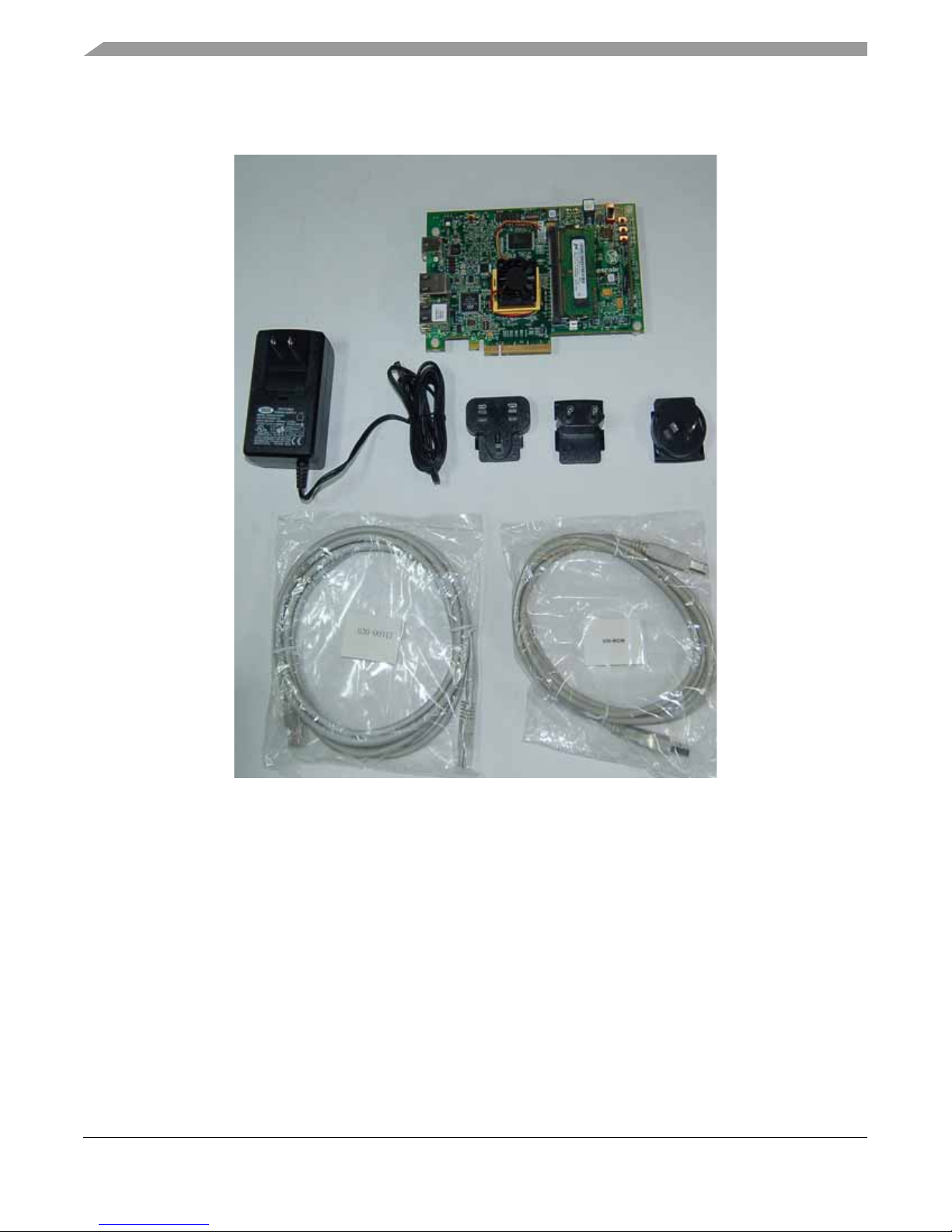
4 Hardware Kit Contents
MSC8156EVM with attached plastic spacers
and screws
AC/DC 12 V/3.0 A universal power supp
One Ethernet cable
USB cable Type A to Type B
Figure 1. Hardware Contents
The kit also includes the following (not shown):
• Packing list that includes a list of printed documents included with the kit. See the list for the
specific documents included with the kit.
• CD-ROM with documentation and code examples.
• Memory stick with ENEA software.
MSC8156-EVM Hardware Getting Started, Rev. 0
4 Freescale Semiconduct or
Page 5
DIP Switch Location Default Settings
5
4
3
SW6
5 DIP Switch Location Default Settings
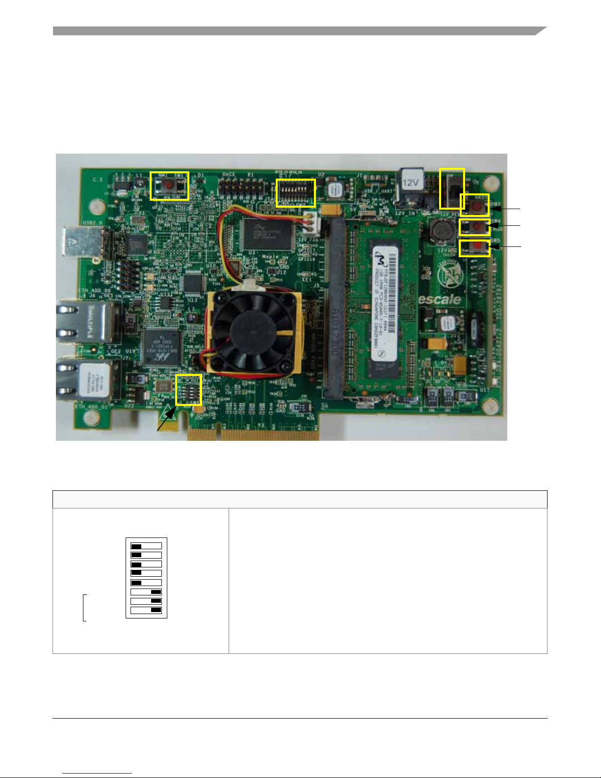
The MSC8156EVM has four push-button switches (SW1, SW3, SW4, and SW5), one slide power switch
(S1), and two dual-in-line package (DIP) switches (SW2 and SW6). See Figure 2 for switch locations and
Table 3 for the default DIP switch settings See Table 5 for push-button and power switch functions.
SW1
SW2
S1
SW
SW
SW
Figure 2. MSC8156EVM Switch Locations
Table 3. MSC8156EVM DIP-Switch Configurations
SW2 Configuration
SW2.1: EE0
ON ‘0’
EE0
GPIO_19
GPIO_20
TP5
RC9
RC8
RC7
81
MSC8156-EVM Hardware Getting Started, Rev. 0
Freescale Semiconduc tor 5
• Default: OFF (disable);
SW2.2: GPIO_19:USER PROGRAMBL E
• Default: OFF (disable)
SW2.3: GPIO_20:USER PROGRAMBL E
• Default: OFF (disable)
SW2.4: Test Point (general purpose)
• Default: OFF (disable)
SW2.5: empty
SW2.6-2.8: Reset Configuration Word bits 7– 9
• Default: ON (“000”)
• Defines the boot port interface configuration.
Page 6
Power Switch and Push Buttons
Table 3. MSC8156EVM DIP-Switch Configurations (continued)
SW6 Configuration
1
SS0
S1
S0
MUX ELECT
4
ON ‘0’
SW6.1:SS0: SELECT PEX SPREAD SPECTRUM
• Default: ON (= 0 which selects NO SPREAD SPECTRUM)
SW6.2-3: S1,S0” SELECT ICS557-03 OUTPUT FREQUENCY
• Default: OFF, ON (= 10 which selects CLKOUT = 100 MHz)
SW6.4: MULTIPLEXER SELECT
• Default: OFF (= 1 which selects INTERNAL CLK).
The default DIP-switch positions define the MSC8156EVM configuration modes listed in Table 4.
.
Table 4. MSC8156EVM Default Configuration Modes
Mode Value
CLKIN 100 MHz
Core frequency 1000 MHz
DDR2 data rate 800 Mbps
MAPLE clock 450 MHz
QUICC Engine
Subsystem clock
PCI Express interface
output rate
500 MHz
2.5 Gbps
6 Power Switch and Push Buttons
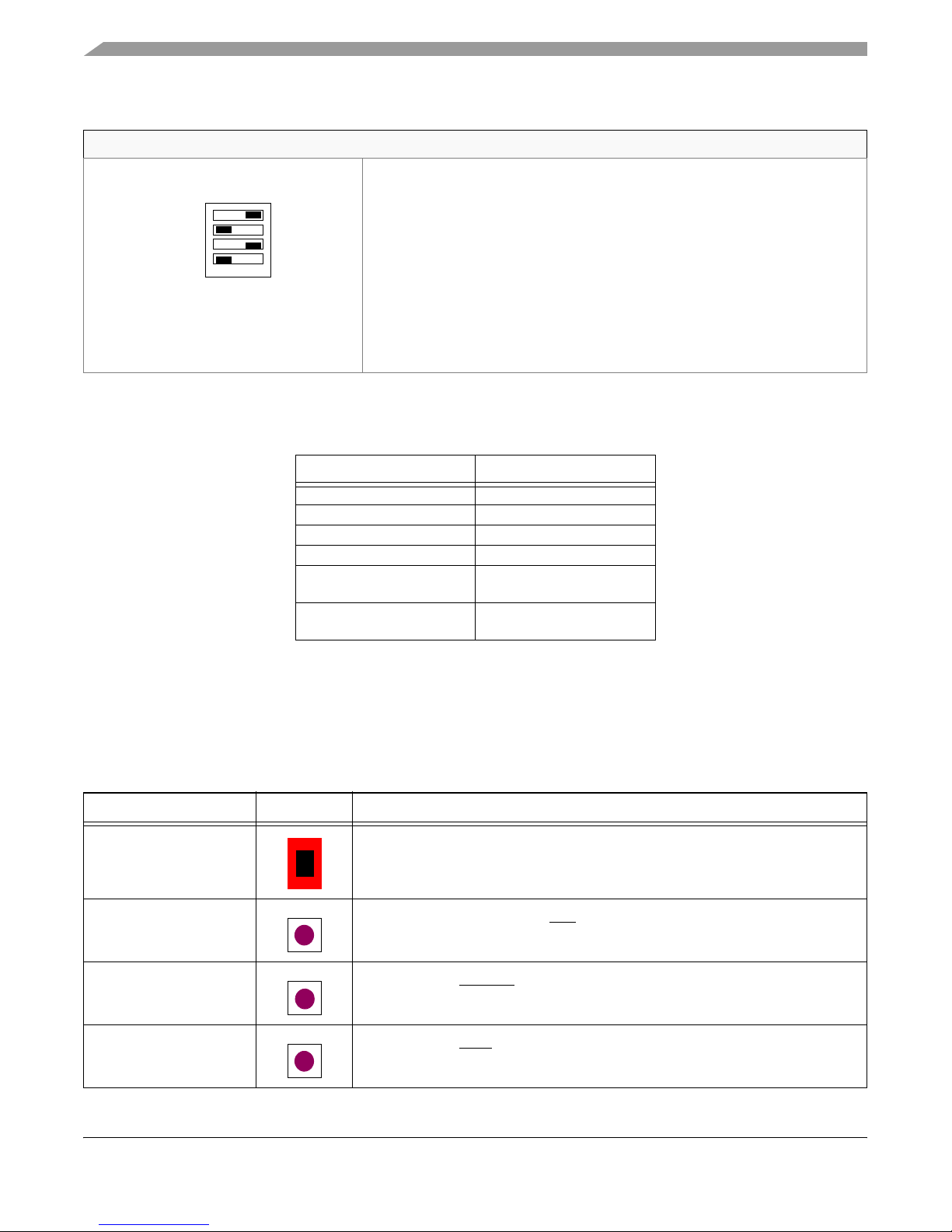
Table 5 lists the functioning of the MSC8156EVM power switch and push buttons. Figure 2 on page 5
shows their location.
Table 5. Power Switch and Push Button Functionality
Push Button Position Description & Default
Power switch. The ON position activates the external power supply. The OFF
S1: ON/OFF
SW1: NMI Pressing this switch assert an NMI
SW3: HRST Press to assert HRESET
SW4: IRQ0 Press to assert IRQ0 to the board.
position connect s power from the PCI Ex press edge-connector , whi ch supplies 12
V power if the PCI-Express external board is connected and powered.
and aborts program execution.
.
MSC8156-EVM Hardware Getting Started, Rev. 0
6 Freescale Semiconduct or
Page 7
Jumper Default Settings
J5
P1
J
Table 5. Power Switch and Push Button Functionality
Push Button Position Description & Default
SW5: PRESET Press to assert PRESET to all board components.
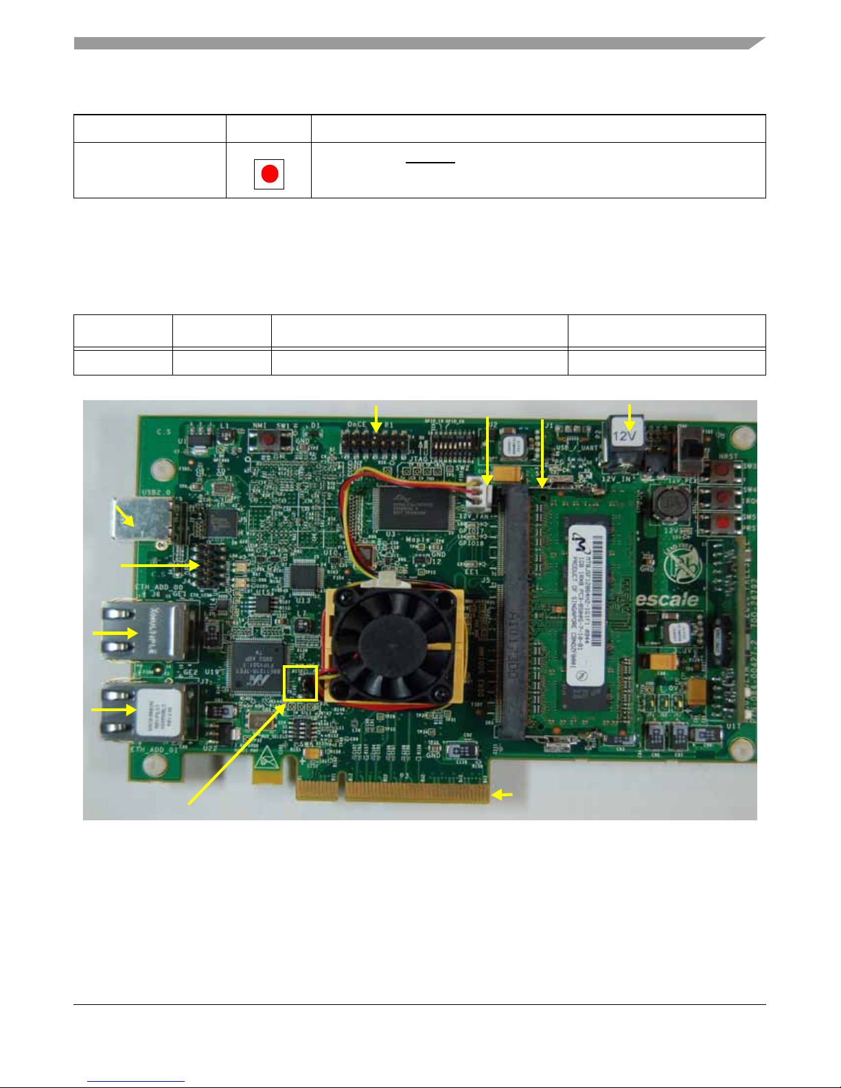
7 Jumper Default Settings
Table 6 lists MSC8156EVM factory default jumper setting. See Figure 3 for jumper location.
Table 6. MSC8156EVM Jumper Default Settings
Jumper Name 1-2 Position 2-3 Position (default)
JP1 RCW_SRC External 22-bits (reduced) Configuration Word I2C EEPROM RCW
J6
7
J3
J4
JP1
J2002
J2004
J2005
J2
P2
P3
Figure 3. MSC8156EVM Jumper (JP) and Connector (J/P) Locations
Freescale Semiconduc tor 7
MSC8156-EVM Hardware Getting Started, Rev. 0
Page 8
Connector Default Settings
8 Connector Default Settings
Table 7 lists MSC8156EVM factory default connector, header , and socket settings. See Figure 3 on page 7
for connector locations.
Table 7. MSC8156EVM Connector Default Settings
# Type Description Function
J2 Header (3-pin) 12V FAN • Provides power for on-socket fan.
J3 Socket (Ty pe B) USB2.0 • USB2.0 interface
J4 Header (10-pin) DPI • MPC866 debug port connector
J5 SODIMM Socket (204-pin) DDR3-SODIMM • DDR3 SODIMM socket
J6 Connector (RJ45) GE1 • MSC8156 GETH port1 1000-BaseT
J7 Connector (RJ45) GE2 • MSC8156 GETH port2 1000-BaseT
P1 Header (14-pin) OnCE • OnCE connector for external UTAP
P2 Power Connector 12V • External power supply
P3 Edge Connector PCIe Backplane • SerDes high-speed connector
The following list provides brief descriptions of how the connectors are used:
• J2. Provides power to the on-socket fan.
• J3. Provides the default connection between the host PC and the MSC8156EVM for debugging and
configuration purposes. Connects to the onboard UTAP.
• J4. Provides an MPC866 debug port connection.
• J5. Used to connect the DDR3 SODIMM.
• J6. The gigabit Ethernet port 1 connection. This port can be connected to the host PC or other
Ethernet connection to use for boot over Ethernet or other device configuration operations.
• J7. The gigabit Ethernet port 2 connection. This port can be connected to the host PC or other
Ethernet connection to use for boot over Ethernet or other device configuration operations.
• P1. The alternate connection between the host PC and the MSC8156EVM for debugging and
configuration purposes. This interface requires the use of an external device, such as a USB T AP,
to transform the Host interface to JTAG signals that connects through a 14-pin ribbon cable.
• P2. Provides a connection to the external 12 V power supply.
• P3: Provides a connection to a PCI Express board only. The PCI Express edge connector is
designed to connect one of the two SerDes ports (SerDes2) of the MSC8156 device. The four
SerDes2 lanes can be configured to support serial RapidIO (1x/2x/4x), PCI Express (1x/2x/4x), or
SGMII connections. When connected, the PCI Express interface can supply the 12 V power for the
MSC8156EVM, which is enabled when S1 is in the OFF position. The connector is designed to
conform to several QorIQ development platforms from Freescale Semiconductor. Contact your
Freescale sales office for more information. Basic drivers are provided as part of the SmartDSP OS
software shipped with the CodeWarrior IDE and the EVM update software. The software is
delivered as an enablement intended for use by customers to develop applications.
NOTE
The PCI Express edge connector is not PCIMIG certified.
MSC8156-EVM Hardware Getting Started, Rev. 0
8 Freescale Semiconduct or
Page 9
9LED Indicators
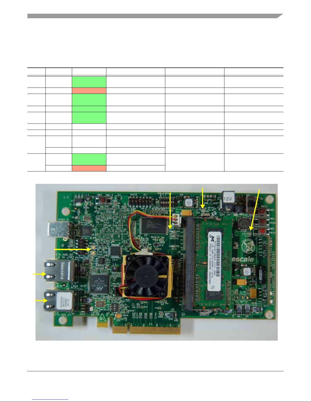
Table 8 lists MSC8156EVM LED indicator functions. See Figure 4 for LED locations.
Table 8. MSC8156EVM LEDs
Ref. Name Color LED On LED Blinking LED Off
LD1 PG Green Power Good —
LD2 GPIO17
LD3 12V Green
LD4 GPIO18
LD5 EE1
LD6 HOST Multicolor eUTAP mode indication — —
LD7 TARGET Multicolor eUTAP mode indication — —
LEDs
in J6
LEDs
in J7
LINK Green
ACT Orange RGMII PHY1 is active
LINK
ACT
Orange USER DEFINE. USER DEFINE. USER DEFINE.
Indicates external power
or PCIe 1 2V Power is ON
Green USER DEFINE. USER DEFINE. USER DEFINE.
Green MSC8156 in Debug mode —
RGMII PHY1 has Link at
1Gbps
Green
Orange RGMII PHY 2 is active
RGMII PHY 2 has link at
1Gbps
Activity (not connected,
should never light)
— The EVM is powered off
Activity
Internal power supply
failure
MSC8156 not in Debug
mode
No link on Port1
No link on Port2
LED Indicators
LD 6& 7
LEDS in J6
LEDS in J7
LD 2 & 4
LD 1
LD 3
Figure 4. MSC8156EVM LED Locations
MSC8156-EVM Hardware Getting Started, Rev. 0
Freescale Semiconduc tor 9
Page 10
Getting Started Procedure
10 Getting Started Procedure
Use the following steps to set up and initial the EVM:
1. Review the kit contents as listed in Section 4 Hardware Kit Contents and make sure you have all the
components.
2. Review the default switch settings as listed in Section 5 DIP Switch Location Default Settings and
verify that all switches on the board are set correctly.
3. Review the jumper settings as listed in Section 7 Jumper Default Settings and verify that all jumpers
are set correctly for your desired configuration.
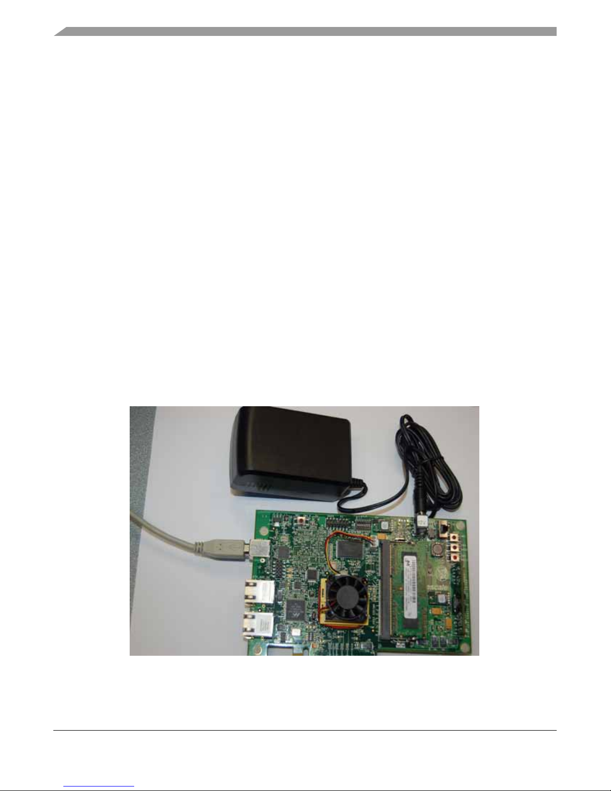
4. Assemble and connect the 12 V power supply (see Figure 5) using the following steps:
a) Make sure that all power is turned off.
b) Assemble the AC/DC power supply kit, as follows:
— Attach the power cable with the country-specific wall output plug for your area.
— Attach the cable with the plug for the board connection.
c) Connect the AC/DC power supply cable to the 12 V (P5) board jack.
d) Plug the power cable into the wall outlet.
5. Referring to the information listed in Section 6 Power Switch and Push Buttons and Section 9 LED
Indicators, perform the initial power up and check using the following steps:
a) Move the power switch (S1) to the ON position, and check for completion of the PRESET
sequence; LEDs 3 (12V POWER) and LED 1 (POWER GOOD) display a constant green light.
b) Power the system off by moving the power switch (S1) to the OFF position.
Figure 5. Power and Cable Connections
MSC8156-EVM Hardware Getting Started, Rev. 0
10 Freescale Semiconduct or
Page 11

Next Steps
11 Next Steps
The procedures in this document describe the basic hardware setup. Once board operation is verified, you
can proceed to download the Freescale CodeW arrior IDE software to your host PC. See the MSC8156EVM
Software Installation Guide included on the kit documentation CD.
Once the software is set up, you can connect the USB cable between the MSC8156EVM J13 and the
development platform (PC or laptop, for example) with the CodeWarrior software installed to begin the
configuration and debugging process. Alternately , you can use the alternate debugging connection through
an external USB tap connected through a 14-pin ribbon cable to the 14-ping OnCE/JTAG header on the
board. Further instructions for running a debug session are provided in the application note Configuring a
CodeWarrior for StarCore DSPs Project for the MSC8156EVM Board (AN4229) included on your
documentation CD.
You may configure the MSC8156 to use the Ethernet ports (J6 and J7). A single Ethernet cable is supplied
with the EVM to allow connection between the EVM and an external Ethernet switch. An Ethernet
crossover cable (not supplied) can be used for a direct connection to an Ethernet port on an external PC,
for example. Basic Ethernet drivers are provided as part of the SmartDSP OS software shipped with the
CodeW arrior IDE and the EVM update software. This software is delivered as an enablement, intended for
use by customers to develop applications.
MSC8156-EVM Hardware Getting Started, Rev. 0
Freescale Semiconduc tor 11
Page 12

How to Reach Us:
Home Page:
www.freescale.com
Web Support:
http://www.freescale.com/support
USA/Europe or Locations Not Listed:
Freescale Semiconductor, Inc.
Technical Information Center, EL516
2100 East Elliot Road
Tempe, Arizona 85284
+1-800-521-6274 or
+1-480-768-2130
www.freescale.com/support
Europe, Middle East, and Africa:
Freescale Halbleiter Deutschland GmbH
Technical Information Center
Schatzbogen 7
81829 Muenchen, Germany
+44 1296 380 456 (English)
+46 8 52200080 (English)
+49 89 92103 559 (German)
+33 1 69 35 48 48 (French)
www.freescale.com/support
Japan:
Freescale Semiconductor Japan Ltd.
Headquarters
ARCO Tower 15F
1-8-1, Shimo-Meguro, Meguro-ku
Tokyo 153-0064
Japan
0120 191014 or
+81 3 5437 9125
[email protected]
Asia/Pacific:
Freescale Semiconductor China Ltd.
Exchange Building 23F
No. 118 Jianguo Road
Chaoyang District
Beijing 100022
China
+86 010 5879 8000
[email protected]
For Literature Requests Only:
Freescale Semiconductor
Literature Distribution Center
+1-800 441-2447 or
+1-303-675-2140
Fax: +1-303-675-2150
LDCForFreescaleSemiconductor
@hibbertgroup.com
Information in this document is provided solely to enable system and software
implementers to use Freescale Semiconductor products. There are no express or
implied copyright licenses granted hereunder to design or fabricate any integrated
circuits or integrated circuits based on the information in t his document.
Freescale Semiconductor reserves the right to make changes without further notice to
any products herein. Freescale Semiconductor makes no warranty, representation or
guarantee regarding the suitability of its products for any particular purpose, nor does
Freescale Semiconductor assume any liability arising out of the application or use of
any product or circuit, and specifically disclaims any and all liability, including without
limitation consequential or incidental damages. “Typical” parameters which may be
provided in Freescale Semiconductor data sheets and/or specifications can and do
vary in different applications and actual performance may vary over time. All operating
parameters, including “Typicals” must be validated for each customer application by
customer’s technical experts. Freescale Semiconductor does not convey any license
under its patent rights nor the rights of others. Freescale Semiconductor products are
not designed, intended, or authorized for use as components in systems intended for
surgical implant into the body, or other applications intended to support or sustain life,
or for any other application in which the failure of the Freescale Semiconductor product
could create a situat ion where personal injury or death may occur. Should Buyer
purchase or use Freescale Semiconductor products for any such unintended or
unauthorized application, Buyer shall indemnify and hold Freescale Semiconductor
and its officers, employees, subsidiaries, affiliates, and distributors harmless against all
claims, costs, damages, and expenses, and reasonable attorney fees arising out of,
directly or indirectly, any claim of personal injury or death associated with such
unintended or unauthorized use, even if such claim alleges that Freescale
Semiconductor was negligent regarding the design or manufacture of the part.
Freescale, the Freescale logo, CodeWarrior, and StarCore are trademarks of
Freescale Semiconductor, Inc., Reg. U.S. Pat. & Tm. Off. QUICC Engine is a
trademark of Freescale Semiconductor, Inc. All other product or service names are the
property of their respective owners.
© 2010 Freescale Semiconductor, Inc.
Document Number: MSC8156EVMHGSG
Rev. 0, 10/2010
 Loading...