

Page 1

Freescale Semiconductor
Document Number: MPC8572EAMCGSG
Rev. 1.0, 08/2008
MPC8572E Advanced Mezzanine Card
Hardware Getting Started Guide
About this Document
This document describes how to connect to the
MPC8572EAMC and verify its basic operation. Settings for
the switches and jumpers are shown, as well as instruction
for connecting peripheral devices. In addition, instructions
for connecting a debugger to the MPC8572EAMC, such as
Freescale’ s CodeWarrior are included, but instructions for
working with this debugger are beyond the scope of this
document.
Required Reading
It is assumed that the reader is familiar with the MPC8572E
microprocessor and MPC8572E PowerQUICC™ III
Integrated Host Processor Family Reference Manual as well
as the content of the High Level Design Document for
MPC8572EAMC.
Contents
1. Check Switches . . . . . . . . . . . . . . . . . . . . . . . . . . . . . . 3
2. Assemble and Connect the Board . . . . . . . . . . . . . . . . 6
3. Perform Initial Board Power Up and Check LEDs . . . 6
4. Connecting JTAG Debugging Tools to the Board . . . 8
5. Front Panel Connectivity . . . . . . . . . . . . . . . . . . . . . . 8
6. Module Management Support . . . . . . . . . . . . . . . . . . 9
7. Revision History . . . . . . . . . . . . . . . . . . . . . . . . . . . . 12
© Freescale Semiconductor, Inc., 2008. All rights reserved.
Page 2

Definitions, Acronyms, and Abbreviations
Table 1. Definitions, Acronyms, and Abbreviations
AdvancedMC Advanced mezzanine card
AMC Advanced mezzanine card
ATCA Advanced telecommunications computing platform
BDM Background debugging mode
CCB Core complex bus
COP Computer operating properly
CPLD Complex programmable logic device
DIP Dual in-line package
DSP Digital signal processor
DUART Dual universal asynchronous receive transmit
EEPROM Electrically erasable programmable read-only module
GETH Gigabit Ethernet
HW Hardware
I2C (bus) Inter-IC bus
MMC Module management controller
SRIO Serial RapidIO
UART Universal asynchronous receive transmit
USB Universal serial bus
μTCA micro telecommunications computing architecture
MPC8572E Advanced Mezzanine Card Hardware Getting Started Guide, Rev. 1.0
2 Freescale Semiconductor
Page 3
Check S witches
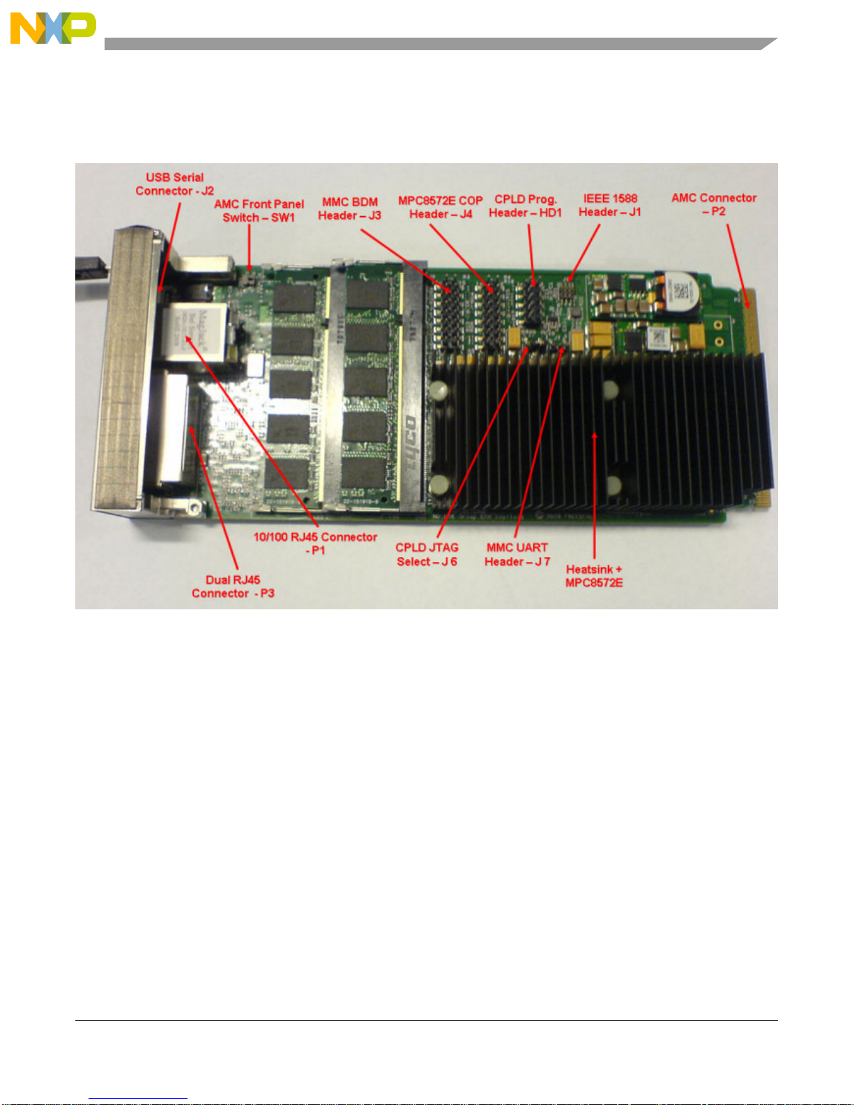
Figure 1 illustrates the main header and switch locations on the top (processor) side of the
MPC8572EAMC. Users should follow this getting started guide prior to applying power to the card,
because incorrect board settings can cause permanent board damage.
Figure 1. MPC8572EAMC Primary Side Header Positions
1 Check Switches
1. DIP Switch settings should only be changed when power is NOT applied to the board.
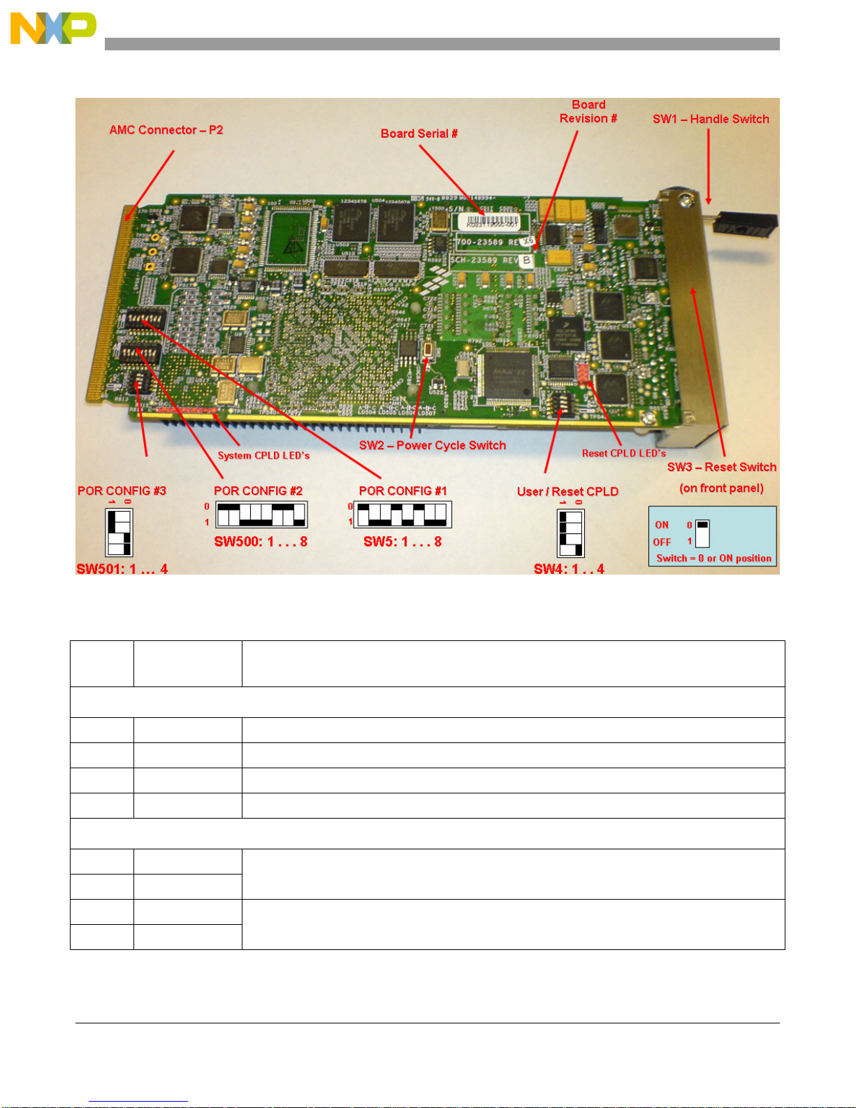
2. The MPC8572EAMC board has three push button switches (SW1, SW2 and SW3), four Dual In
line Package (DIP) switches (SW4, SW5, SW500, and SW501), and eight jumper headers (J1–J7
and HD1). The default DIP switch positions pr ovide Power On Reset configuration values for the
MPC8572EAMC board. Check the default positions and verify the board is operational before
changing the switches. The settings for the switches are shown in Figure 2, with their default
positions as described in Table 2. Table 6 gives a full list of all possible switch configurations.
3. Jumper headers J3, J6, and HD1 are reserved for factory test and are used to program the module
management controller and Reset/System CPLDs. Users should not attempt to reprogram the card
using these headers because this may result in permanent card damage. The jumpers should
remain in their default position as detailed in Table 3.
MPC8572E Advanced Mezzanine Card Hardware Getting Started Guide, Rev. 1.0
Freescale Semiconductor 3
Page 4
Check Switches
Figure 2. Secondary Side Switch Positions
Table 2. Default Switch Settings
Feature
SW4.1 OFF Reserved
SW4.2 OFF Reserved
SW4.3 OFF Reserved
SW4.4 ON [SW4.4] = MMC H/W Select. ON—MMC present
SW5.1 ON [SW5.1:2] = ON:OFF. CCB:SYSCLK = 10:1 (666 MHz)
SW5.2 OFF
SW5.3 OFF [SW5.3:4] = OFF:ON. e500 Core #0:CCB = 2:1
SW5.4 ON
Default Settings
[OFF = 1, ON = 0)
Comments
SW4
SW5
MPC8572E Advanced Mezzanine Card Hardware Getting Started Guide, Rev. 1.0
4 Freescale Semiconductor
Page 5
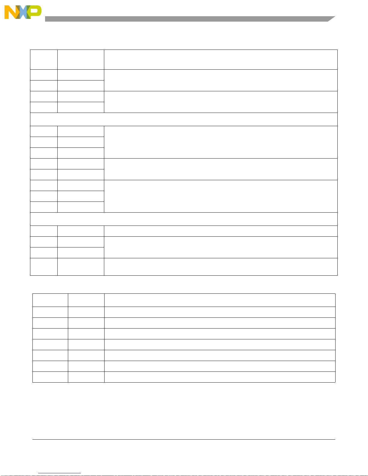
Table 2. Default Switch Settings (continued)
Check S witches
Feature
SW5.5 OFF [SW5.5:6] = OFF:ON. e500 Core #1:CCB = 2:1
SW5.6 ON
SW5.7 OFF [SW5.7:8] = OFF:OFF. Boot ROM Location = 32-bit Local FLASH Memory
SW5.8 OFF
SW500.1 ON [SW500.1:3]=ON:ON:OFF.DDR Clock Ratio = 10:1 DDRCLK (666 MHz)
SW500.2 ON
SW500.3 OFF
SW500.4 OFF [SW500.4:5] = OFF:OFF. MPC8572E acts as the host processor
SW500.5 OFF
SW500.6 ON [SW500.6:8] = ON:ON:OFF. IO Port Selection = SRIO 125 MHz, 3.125 Gbps (x4)
SW500.7 ON
SW500.8 OFF
Default Settings
[OFF = 1, ON = 0)
Comments
SW500
SW501
SW501.1 OFF [SW501.1] = OFF Boot Sequence Configuration = Boot Sequencer Disabled
SW501.2 OFF CPU Boot Config:
SW501.3 ON
SW501.4 ON RIO System Size:
[SW501.2:3] = OFF:ON. E500 Core 0 allowed to boot, Core 1 in boot hold-off
[SW501.4] = ON. Large system size, up to 65,536 devices
Table 3. Header Configuration/Availability
Feature Status Comments
J1 Available IEEE Std 1588™ header
J2 Available USB DUART Connection. Provides debug information from MPC8572E Core #0 /1.
J3 — MMC BDM Debug header. Reserved for factory use only.
J4 Available COP Debug Header
J6 — CPLD JTAG Select. Reserved for factory use only.
J7 Available Pin 1 = TxD, Pin 2 = RxD, Pin 3 = GND. Connect for console debug information from MMC only.
HD1 — CPLD Programming Header. Reserved for factory use only.
MPC8572E Advanced Mezzanine Card Hardware Getting Started Guide, Rev. 1.0
Freescale Semiconductor 5
Page 6
Assemble and Connect the Board
Table 4. Push Switches
Feature Switch Function Comments
SW1 AdvancedMC hot swap Micro switch used to detect AdvancedMC handle position
SW2 Power cycle switch Push button switch used to power cycle the AdvancedMC
SW3 Reset switch Push button switch used for hard reset of the processor
2 Assemble and Connect the Board
1. The heat sink must be fitted to the processor at all times.
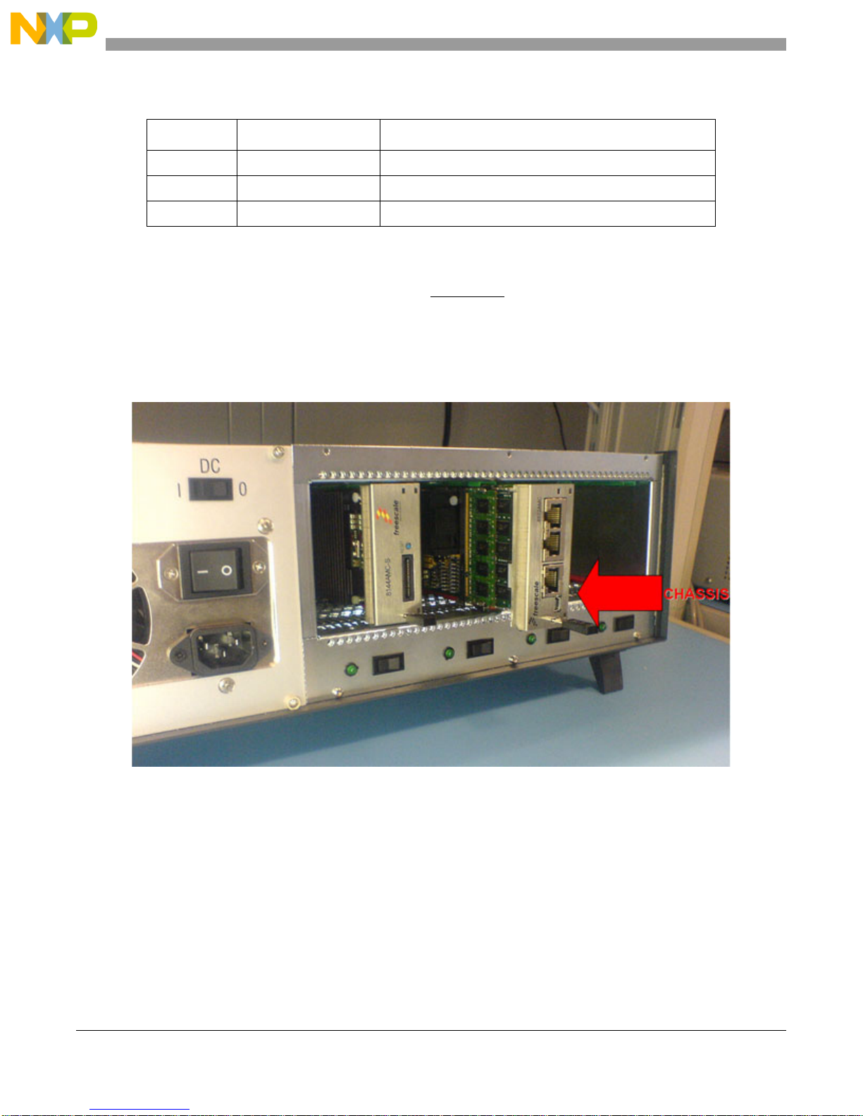
2. Freescale recommends running the AdvancedMC in an ATCA, microTCA, picoTCA chassis or
equivalent. This delivers the correct power and air flow to the board. The board should be inserted
into the carrier chassis as per the specific carrier instructions. Please ensure the card is inserted the
correct way. An example is shown in Figure 3.
Figure 3. Inserting the MPC8572EAMC into a Chassis
3 Perform Initial Board Power Up and Check LEDs
A complete list of all LEDs on the MPC8572EAMC is shown in Table 5.
1. Switch on the power to the chassis.
2. Check for the blue front panel LED and power good LEDs being illuminated (a full description of
the LED operation is given in Table 5).
MPC8572E Advanced Mezzanine Card Hardware Getting Started Guide, Rev. 1.0
6 Freescale Semiconductor
Page 7

Perform Initial Board Power Up and Check LEDs
3. When powered up:
a) Blue front panel LED remains illuminated as long as power is applied to the board (via the
AdvancedMC backplane connector).
b) Ethernet port activity LEDs switch on to indicate any Ethernet link to the front or back planes.
c) The “System Status” LED, LD507, switches on, then goes off once system configuration is
complete. LED LD506 should stay on indicating the processor is “Ready. ”
d) Any USB UART activity is shown on LEDs D507 and D508.
4. Pressing the power cycle button (SW2) power cycles the board and start the reset sequence.
5. Pressing the reset button (SW3) starts the reset sequence only.
Table 5. LED Operation
Description Ref Color LED On LED Off
MMC red LED LD1 Red MMC control Normal operation
MMC card power blue LED LD500 Blue Hot swap state Hot swap state
Port 0 AMC SERDES Ethernet Rx activity D500 Green Rx Ethernet activity No Rx Ethernet activity
Port 0 AMC SERDES Ethernet Tx activity D501 Yellow Tx Ethernet activity No Tx Ethernet activity
Port 0 AMC SERDES LOS D502 Orange Loss of signal No loss of signal
Port 1 AMC SERDES LOS D504 Orange Loss of signal No loss of signal
Port 1 AMC SERDES Ethernet Tx activity D505 Yellow Tx Ethernet activity No Tx Ethernet activity
Port 1 AMC SERDES Ethernet Rx activity D506 Green Rx Ethernet activity No Rx Ethernet activity
USB/UART 1 activity D507 Orange UART 1 activity No UART 1 activity
USB/UART 0 activity D508 Orange UART 0 activity No UART 0 activity
Front panel dual RJ45 Ethernet Rx activity P3:D1-2a Green Rx Ethernet activity No Rx Ethernet activity
Front panel dual RJ45 Ethernet Tx activity P3:D1-4a Yellow Tx Ethernet activity No Tx Ethernet activity
Front panel dual RJ45 Ethernet Rx activity P3:D1-2b Green Rx Ethernet activity No Rx Ethernet activity
Front panel dual RJ45 Ethernet Tx activity P3:D1-4b Yellow Tx Ethernet activity No Tx Ethernet activity
Front panel 10/100 RJ45 Ethernet Rx activity P1 Orange/
Green
Front panel 10/100 RJ45 Ethernet Tx activity P1 Yellow Tx Ethernet activity No Tx Ethernet activity
General debug system CPLD LD507 Green System CPLD
General debug system CPLD LD506 Green Ready signal POR config cycles
General debug system CPLD LD505 Yellow Default on User debug #1
Rx Ethernet activity No Rx Ethernet activity
System CPLD execution
execution not
complete
complete
unsuccessful
General debug system CPLD LD504 Yellow Default on User debug #2
General debug POR CPLD LD502 Green User config #1 User config #1
MPC8572E Advanced Mezzanine Card Hardware Getting Started Guide, Rev. 1.0
Freescale Semiconductor 7
Page 8
Connecting JTAG Debugging Tools to the Board
Table 5. LED Operation (continued)
Description Ref Color LED On LED Off
General debug POR CPLD LD501 Yellow User config #2 User config #2
General debug POR CPLD LD503 Yellow User config #3 User config #3
4 Connecting JTAG Debugging Tools to the Board
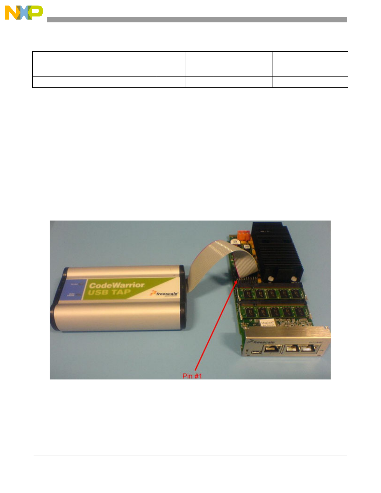
Figure 4 illustrates an example of how to connect a JT AG debugger to the MPC8572EAMC. The USB tap
debugging tool enables the CodeWarrior software IDE to work with the MPC8572EAMC board.
1. Connect the JT AG debugger unit to the JTAG 16-pin connector (J4).
2. Connect USB cable from Host PC (with CodeWarr ior Power Architecture™ tools installed on it)
to CodeW ar rior USB Tap. Figure 4 illustrates Freescale’s CodeWarrior debugger connected to the
MPC8572EAMC. Note the orientation of pin 1 (red edge of ribbon cable) with pin 1 on J4.
3. Switch on power to the board.
4. Check for completion of the reset sequence (see step 3) and power indicator on USB Tap.
5. Continue as per standard CodeWarrior instructions.
a) Contact your local FAE for the correct JTAG configuration file.
Figure 4. USB TAP Connection to Header J4
5 Front Panel Connectivity
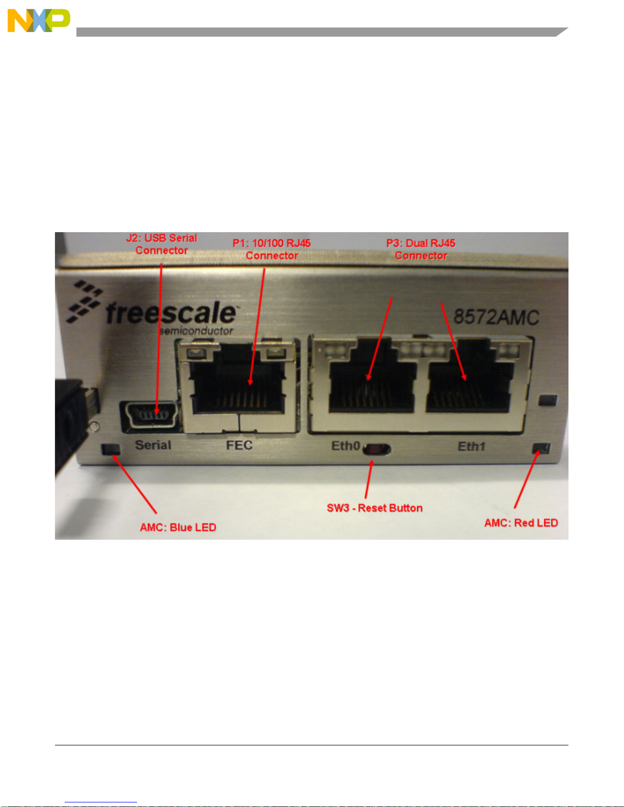
Figure 5 shows the different front panel connections. P1 provides a RJ45 10/100 Ethernet port. The final
front panel connector P3 provides two high speed Gigabit Ethernet connections. Serial connectivity for
MPC8572E Advanced Mezzanine Card Hardware Getting Started Guide, Rev. 1.0
8 Freescale Semiconductor
Page 9
Module Management Support
both dual cores is provided via USB serial connector J2. Users should note that USB drivers should be
installed onto the host PC before the serial terminal can be used. These can be downloaded from the
following URL: http://www.ftdichip.com/FTDrivers.htm
A serial terminal can be setup using a PC communication program such as Hyperterminal set to 115200
baud rate. If the USB session hangs the terminal then the communication link must be disconnected and
then reconnected.
Any board settings that users wish to make should be checked for validity against a recent version of the
MPC8572E PowerQUICC™ III Integrated Host Processor Family Reference Manual. Operating the
board, or MPC8572E device, beyond the recommended device operating conditions may cause permanent
board damage.
Figure 5. MPC8572EAMC Front Panel Connectivity
6 Module Management Support
The MPC8572EAMC contains a CorEdge™-enabled module management controller (MMC), which
meets the PICMG and intelligent platform management interface (IPMI) AdvancedMC specifications.
This enables the board to be hot swapped in or out of an MMC-compatible system. To hot swap a board,
complete the following steps:
Hot swapping in a board:
1. Set switch SW4.4 to ON to select the MMC present option.
MPC8572E Advanced Mezzanine Card Hardware Getting Started Guide, Rev. 1.0
Freescale Semiconductor 9
Page 10
Module Management Support
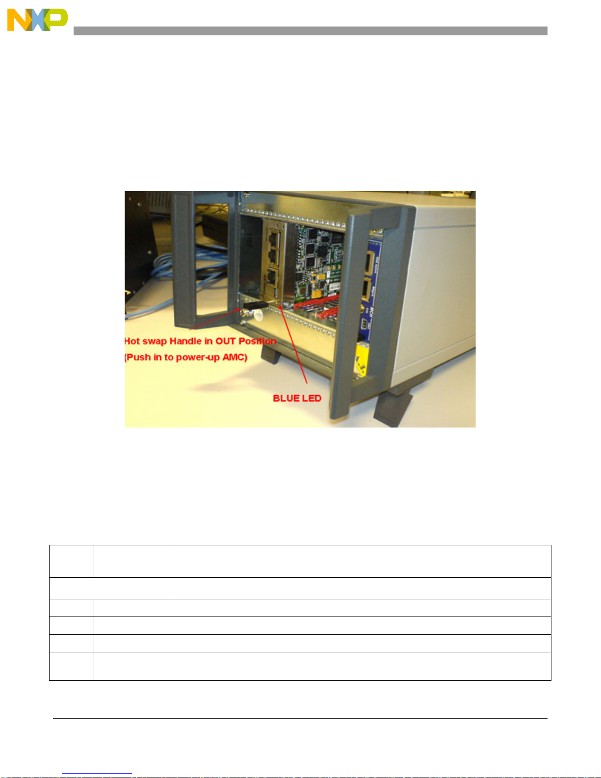
2. Insert the AdvancedMC into the slot with the handle extracted. The BLUE LED switches ON once
it is inserted.
3. Close the handle. The BLUE LED flashes and then switches OFF. The board powers up.
Hot swapping out a board:
1. Extract the hot swap handle
2. The BLUE LED flashes and then stays ON.
3. When the BLUE LED is ON, the AdvancedMC can be removed from the chassis.
Figure 6. Hot Swapping in a Chassis
NOTE
While the chassis shown in Figure 6 is MMC-compatible, the chassis shown
in Figure 3 is not.
Table 6 lists the complete switch settings.
Table 6. Complete Switch Settings
Feature
SW4.1 OFF Reserved
SW4.2 OFF Reserved
SW4.3 OFF Reserved
SW4.4 ON [SW4.4] = MMC H/W Select. ON—MMC present
Default Settings
[OFF = 1, ON = 0)
MPC8572E Advanced Mezzanine Card Hardware Getting Started Guide, Rev. 1.0
Comments
SW4
[SW4.4] = MMC H/W Select. OFF—MMC not present
1
10 Freescale Semiconductor
Page 11
Table 6. Complete Switch Settings (continued)
Module Management Support
Feature
Default Settings
[OFF = 1, ON = 0)
Comments
SW5
SW5.1 ON [SW5.1:2] = ON:ON. CCB:SYSCLK = 4:1 (266 MHz)
SW5.2 OFF
[SW5.1:2] = OFF:ON. CCB:SYSCLK = 8:1 (533 MHz)
[SW5.1:2] = ON:OFF. CCB:SYSCLK = 10:1 (666 MHz)
1
[SW5.1:2] = OFF:OFF. CCB:SYSCLK = 12:1 (800 MHz)
SW5.3 OFF [SW5.3:4] = ON:ON. e500 Core #0:CCB = 1.5:1
SW5.4 ON
[SW5.3:4] = OFF:ON. e500 Core #0:CCB = 2:1
[SW5.3:4] = ON:OFF. e500 Core #0:CCB = 2.5:1
1
[SW5.3:4] = OFF:OFF. e500 Core #0:CCB = 3.5:
SW5.5 OFF [SW5.5:6] = ON:ON. e500 Core #1:CCB = 1.5:1
SW5.6 ON
[SW5.5:6] = OFF:ON. e500 Core #1:CCB = 2:1
[SW5.5:6] = ON:OFF. e500 Core #1:CCB = 2.5:1
1
[SW5.5:6] = OFF:OFF. e500 Core #1:CCB = 3.5:1
SW5.7 OFF [SW5.7:8] = ON:ON. Boot ROM Location = PCI-Express
SW5.8 OFF
[SW5.7:8] = OFF:ON. Boot ROM Location = Serial RapidIO
[SW5.7:8] = ON:OFF. Boot ROM Location = DDR Memory
[SW5.7:8] = OFF:OFF. Boot ROM Location = 32-bit Local FLASH Memory
SW500
SW500.1 ON [SW500.1:3]=ON:ON:ON.DDR Clock Ratio = 3:1 DDRCLK (200 MHz)
SW500.2 ON
SW500.3 OFF
[SW500.1:3]=OFF:ON:ON.DDR Clock Ratio = 4:1 DDRCLK (266 MHz)
[SW500.1:3]=ON:OFF:ON.DDR Clock Ratio = 6:1 DDRCLK (400 MHz)
[SW500.1:3]=OFF:OFF:ON.DDR Clock Ratio = 8:1 DDRCLK (533 MHz)
[SW500.1:3]=ON:ON:OFF.DDR Clock Ratio = 10:1 DDRCLK (666 MHz)
[SW500.1:3]=OFF:ON:OFF.DDR Clock Ratio = 12:1 DDRCLK (800 MHz)
[SW500.1:3]=ON:OFF:OFF. RESERVED
[SW500.1:3]=OFF:OFF:OFF.DDR Clock Ratio = SYNCHRONOUS
1
1
SW500.4 OFF [SW500.4:5] = ON:ON. MPC8572E acts as agent on all interfaces
SW500.5 OFF
[SW500.4:5] = OFF:ON. MPC8572E acts as end point on PCIE #1 host
[SW500.4:5] = ON:OFF. MPC8572E acts as end point on SRIO & PCIE #1 host
[SW500.4:5] = OFF:OFF. MPC8572E acts as the host processor
1
SW500.6 ON [SW500.6:8] = OFF:ON:ON. IO Port Selection = SRIO 100-MHz clock, 2.5 Gbps (x4)
SW500.7 ON
SW500.8 OFF
[SW500.6:8] = ON:OFF:ON. IO Port Selection = SRIO/PCIE 100-MHz clock, 2.5 Gbps
[SW500.6:8] = OFF:OFF:ON. IO Port Selection = SRIO/PCIE 100-MHz clock, 1.25/2.5 Gbps (x4)
[SW500.6:8] = OFF:ON:OFF. IO Port Selection = SRIO 100-MHz clock, 1.25 Gbps (x4)
[SW500.6:8] = ON:ON:OFF. IO Port Selection = SRIO 125 MHz, 3.125 Gbps (x4)
1
SW501
SW501.1 OFF [SW501.1] = ON Boot Sequence Configuration = Boot Sequencer Enabled
[SW501.1] = OFF Boot Sequence Configuration = Boot Sequencer Disabled
SW501.2 OFF CPU Boot Config:
SW501.3 ON
[SW501.2:3] = ON:ON.CPU boot hold-off both cores
[SW501.2:3] = OFF:ON. E500 Core 0 allowed to boot, Core 1 in boot hold-off
1
[SW501.2:3] = ON:OFF. E500 Core 1 allowed to boot, Core 0 in boot hold-off
[SW501.2:3] = OFF:OFF. Both cores boot without external master
MPC8572E Advanced Mezzanine Card Hardware Getting Started Guide, Rev. 1.0
Freescale Semiconductor 11
Page 12

Revision History
Table 6. Complete Switch Settings (continued)
Feature
SW501.4 ON RIO System Size:
Note:
1
Default
Default Settings
[OFF = 1, ON = 0)
Comments
[SW501.4] = ON. Large system size, up to 65,536 devices
[SW501.4] = OFF. Small system size, up to 256 devices
NOTE
Consult your local FAE for further information and card availability.
7 Revision History
Table 7 provides a revision history for this getting started guide.
Table 7. Document Revision History
Rev.
Number
1.0 08/2008 Initial public release.
Date Substantive Change(s)
1
MPC8572E Advanced Mezzanine Card Hardware Getting Started Guide, Rev. 1.0
12 Freescale Semiconductor
Page 13

THIS PAGE INTENTIONALLY LEFT BLANK
Revision History
MPC8572E Advanced Mezzanine Card Hardware Getting Started Guide, Rev. 1.0
Freescale Semiconductor 13
Page 14

Revision History
THIS PAGE INTENTIONALLY LEFT BLANK
MPC8572E Advanced Mezzanine Card Hardware Getting Started Guide, Rev. 1.0
14 Freescale Semiconductor
Page 15

THIS PAGE INTENTIONALLY LEFT BLANK
Revision History
MPC8572E Advanced Mezzanine Card Hardware Getting Started Guide, Rev. 1.0
Freescale Semiconductor 15
Page 16

How to Reach Us:
Home Page:
www.freescale.com
Web Support:
http://www.freescale.com/support
USA/Europe or Locations Not Listed:
Freescale Semiconductor, Inc.
Technical Information Center, EL516
2100 East Elliot Road
Tempe, Arizona 85284
1-800-521-6274 or
+1-480-768-2130
www.freescale.com/support
Europe, Middle East, and Africa:
Freescale Halbleiter Deutschland GmbH
Technical Information Center
Schatzbogen 7
81829 Muenchen, Germany
+44 1296 380 456 (English)
+46 8 52200080 (English)
+49 89 92103 559 (German)
+33 1 69 35 48 48 (French)
www.freescale.com/support
Japan:
Freescale Semiconductor Japan Ltd.
Headquarters
ARCO Tower 15F
1-8-1, Shimo-Meguro, Meguro-ku
Tokyo 153-0064
Japan
0120 191014 or
+81 3 5437 9125
[email protected]
Asia/Pacific:
Freescale Semiconductor China Ltd.
Exchange Building 23F
No. 118 Jianguo Road
Chaoyang District
Beijing 100022
China
+86 10 5879 8000
[email protected]
For Literature Requests Only:
Freescale Semiconductor
Literature Distribution Center
P.O. Box 5405
Denver, Colorado 80217
1-800 441-2447 or
+1-303-675-2140
Fax: +1-303-675-2150
LDCForFreescaleSemiconductor
@hibbertgroup.com
Information in this document is provided solely to enable system and software
implementers to use Freescale Semiconductor products. There are no express or
implied copyright licenses granted hereunder to design or fabricate any integrated
circuits or integrated circuits based on the information in this document .
Freescale Semiconductor reserves the right to make changes without fur ther notice to
any products herein. Freescale Semiconductor makes no warranty, representation or
guarantee regarding the suitability of its products for any particular purpose, nor does
Freescale Semiconductor assume any liability arising out of the application or use of
any product or circuit, and specifically disclaims any and all liability, including without
limitation consequential or incidental damages. “Typical” parameters which may be
provided in Freescale Semiconductor data sheets and/or specifications can and do
vary in different applications and actual performance may vary over time. All operating
parameters, including “Typicals” must be validated for each customer application by
customer’s technical experts. Freescale Semiconductor does not convey any license
under its patent rights nor the rights of others. Freescale Semiconductor products are
not designed, intended, or authorized for use as components in systems intended for
surgical implant into the body, or other applications intended to support or sustain life,
or for any other application in which the failure of the Freescale Semiconductor product
could create a situation where personal injury or death may occur. Should Buyer
purchase or use Freescale Semiconductor products for any such unintended or
unauthorized application, Buyer shall indemn ify and hold Freescale Semiconductor
and its officers, employees, subsidiaries, affiliates, and distributors har mless against all
claims, costs, damages, and expenses, and reasonable attorney fees arising out of,
directly or indirectly, any claim of personal injury or death a ssociated with such
unintended or unauthorized use, even if such claim alleges that Freescale
Semiconductor was negligent regarding the design or manufacture of the par t.
Freescale are trademarks or registered trademarks of Freescale
Semiconductor, Inc. in the U.S. and other countries. All other product or
service names are the property of their respective owners. The Power
Architecture and Power.org word marks and the Power and Power.org logos
and related marks are trademarks and ser vice marks licensed by
Power.org. RapidIO is a registered trademark of the RapidIO Trade
Association. IEEE 1588 is a registered trademark of the Institute of
Electrical and Electronics Engineers, Inc. (IEEE). This product is not
endorsed or approved by the IEEE.
© Freescale Semiconductor, Inc., 2008. All rights reserved.
Document Number: MPC8572EAMCGSG
Rev. 1.0
08/2008
 Loading...