

Page 1

Freescale Semiconductor
User Guide
MCUSLK_CSM12C32
Rev. 0, 6/2005
Getting Started with the Microcontroller
Student Learning Kit (MCUSLK)
Using the MC9S12C32 MCU Application Module (CSM-12C32)
By Eduardo Montañez
Applications Engineering
Austin, Texas
By Spencer Ruggles
Axiom Manufacturing
Garland, Texas
Overview
This document will guide you through all the steps necessary to begin development on an HCS12 Family
microcontroller unit (MCU) using your MCUSLK. The software setup section will assist you install the
Metrowerks’ CodeWarrior software and necessary software to support your MCU Project Board – 2. The
hardware setup section will walk you through configuring the MCU Project Board – 2 for use with the
MC9S12C32 MCU application module (Axiom’s CSM12C32). The development section will show you
how to create, build, and debug your application. Refer to the MCU Project Board – 2 user guide,
MC9S12C32 MCU application module user guide and Metrowerks’ CodeWarrior documentation for
details.
© Freescale Semiconductor, Inc., 2005. All rights reserved.
Page 2

Software Setup
Software Setup
The following software installation is a one-time, required procedure per host PC that you intend to use
with the MCU Project Board – 2. After completing the software setup section on your host PC, you can
then skip the software section on subsequent uses of your project board and begin with the hardware
setup or development sections.
1. To install and register CodeWarrior development tools for HC(S)12 MCUs onto a host PC, follow
the instructions outlined in sections A, B, and C of the CodeWarrior Development Studio for
Freescale 68HC(S)12 Microcontrollers quick start pamphlet found inside the supplied 3-cd case
labeled CodeWarrior Development Studio for HC(S)08 Special Edition and HC(S)12 Special
Edition. Make sure to request the special edition license when registering.
license version of CodeWarrior is necessary for developing applications for the MC9S12C32 MCU
application module board.
2. Install a CodeWarrior service patch labeled “CW12_V3_1_ICD12_USB2_0_Sim_patch.exe”
located in the Service Pack CD found inside the supplied 3-cd case labeled CodeWarrior
Development Studio for HC(S)08 Special Edition and HC(S)12 Special Edition. The patch is
located under the E:\HC(S)12\CW12_V3_1\ directory in the Service Pack CD. Install by doubleclicking on the file and by following the on-screen instructions.
1
The special edition
NOTE
The CW12_V3_1_ICD12_USB2_0_Sim_patch.exe is REQUIRED for the
USB multilink pod on the MCU Project Board – 2 to function with the
Metrowerks CodeWarrior development tools and must be installed prior to
the hardware setup section. Other patches included on the Service Pack
CD are recommended if developing an application on a HC(S)12
microcontroller other than the MC9S12C32.
NOTE
Periodically check the corresponding development tool product page for
patches and updates. For questions on CodeWarrior development tools,
contact [email protected]
1. Registering will email you instructions for how to acquire the special
edition license. After you acquire the special edition license, place it in the
root CodeWarrior directory. If you encounter problems with registration, you
can acquire your special edition license online at
http://www.metrowerks.com/MW/Develop/Embedded/HC12/Downloads
.
Getting Started with the MCUSLK for MC9S12C32 Application Module, Rev. 0
2 Freescale Semiconductor
Page 3

Hardware Setup
Hardware Setup
Unpack
1. Open the shipping carton and remove the contents. Verify that all packing list items have been
received.
2. Inspect both the MCU Project Board – 2 and the MC9S12C32 MCU application module for any
damage that may have occurred during shipping. If damage is found, contact the manufacturer at
Configuring the MCU Project Board – 2
1. To begin, place the MCU Project Board – 2 on a flat sturdy surface. Ensure sufficient space is
available around the project board to safely construct and test prototyped circuits.
2. Verify that all the factory default jumper settings are configured properly on the MCU Project
Board – 2 as shown by Figure 1. Highlighted blocks indicate the “on” or “installed” position of
jumpers. Circles indicate the location on the project board where the jumpers are located. Table 1
summarizes the default state for the jumper settings. Please refer to MCU Project Board – 2 User
Guide for more details and alternative configurations.
for assistance.
Figure 1. MCU Project Board – 2 Default Jumper Settings
Getting Started with the MCUSLK for MC9S12C32 Application Module, Rev. 0
Freescale Semiconductor 3
Page 4

Hardware Setup
Table 1. Summary of Default Jumper Settings (Sheet 1 of 2)
Jumper Position Jumper ID Description
PWR_SEL
J1 VIN
+5V_SEL
USB JP1
VDD_SEL
+5V +3.3V
PS1_EN
J301
HIGH FULL
MODULE
POWER
VDD
GND
JP1
JP2
JP3 Sets V
JP11
USB-ML
-MCUSLK
JP4A
JP4B
Selects V
(wall power transformer) as the default power
In
source for the project board.
Selects USB (power via USB cable from host PC) as the
default power source for the project board. This jumper
overrides PSEL_A in USB position.
to +5 V for project board.
DD
Enables PS1 output (±15 V supply from dc-dc converter) to
the project board.
Selects USB high-speed communications for the BDM
Multilink pod on the project board. If the user encounters a
communication failure, USB communication speed may be
reduced by setting this option jumper to FULL.
Routes V
to MCU_1 and GND to MCU_3 to power a
DD
plugged in application module board on MCU PORT
connector.
SS_SEL
JP5
SS* GPIO
Getting Started with the MCUSLK for MC9S12C32 Application Module, Rev. 0
4 Freescale Semiconductor
Selects dedicated SS
input source to MCU_23 on MCU
PORT connector to transfer data to LCD panel.
Page 5

Table 1. Summary of Default Jumper Settings (Sheet 2 of 2)
Jumper Position Jumper ID Description
CONTRAST
Hardware Setup
ADJ
FIX
COM_SEL
MON08 COM
COM_EN
AMPL
LED_EN
CTS
RTS
RXD
TXD
JP12 Selects fixed LCD contrast voltage.
JP8 Selects RS-232 communications for project board COM port.
JP9
JP7 Oscillator output at reduced amplitude – 3.3 Vpp.
JP6 Enables all LED outputs on project board.
Enables all RS-232 communication signals individually for
project board COM port.
UFEA
Freescale Semiconductor 5
BZ
PB
LED
POT
Enables access to direct connect features for buzzer, four
JP10
Getting Started with the MCUSLK for MC9S12C32 Application Module, Rev. 0
push buttons, four LEDs, and potentiometer to MCU PORT
connector to simplify circuit connections and emphasize
software development.
Page 6

Hardware Setup
3. Configure the MC9S12C32 MCU application module (CSM12C32) PWR_SEL option header.
Install jumpers as shown.
PWR_SEL
1
2
4. Configure the MC9S12C32 MCU application module (CSM12C32) USER option header. Install
jumpers as shown below.
USER
1
2
3
4
5. Install the MC9S12C32 MCU application module in the MCU PORT connector (J5) on the project
board. Align pin 1 on the application module with pin 1 of the MCU PORT connector on the project
board as marked by Figure 2.
PIN 1
4
Figure 2. Installation of MC9S12C32 MCU Application Module
6. Power up your host PC and connect the supplied USB cable to an available USB port on your host
PC.
Prior to executing the following steps, all CodeWarrior development tools
for the HC(S)12 and USB 2.0 service patch software included in the
CodeWarrior Development Studio for HC(S)08 Special Edition and
HC(S)12 Special Edition 3-cd case must be installed per the instructions in
the software setup section.
Getting Started with the MCUSLK for MC9S12C32 Application Module, Rev. 0
6 Freescale Semiconductor
NOTE
Page 7
Hardware Setup
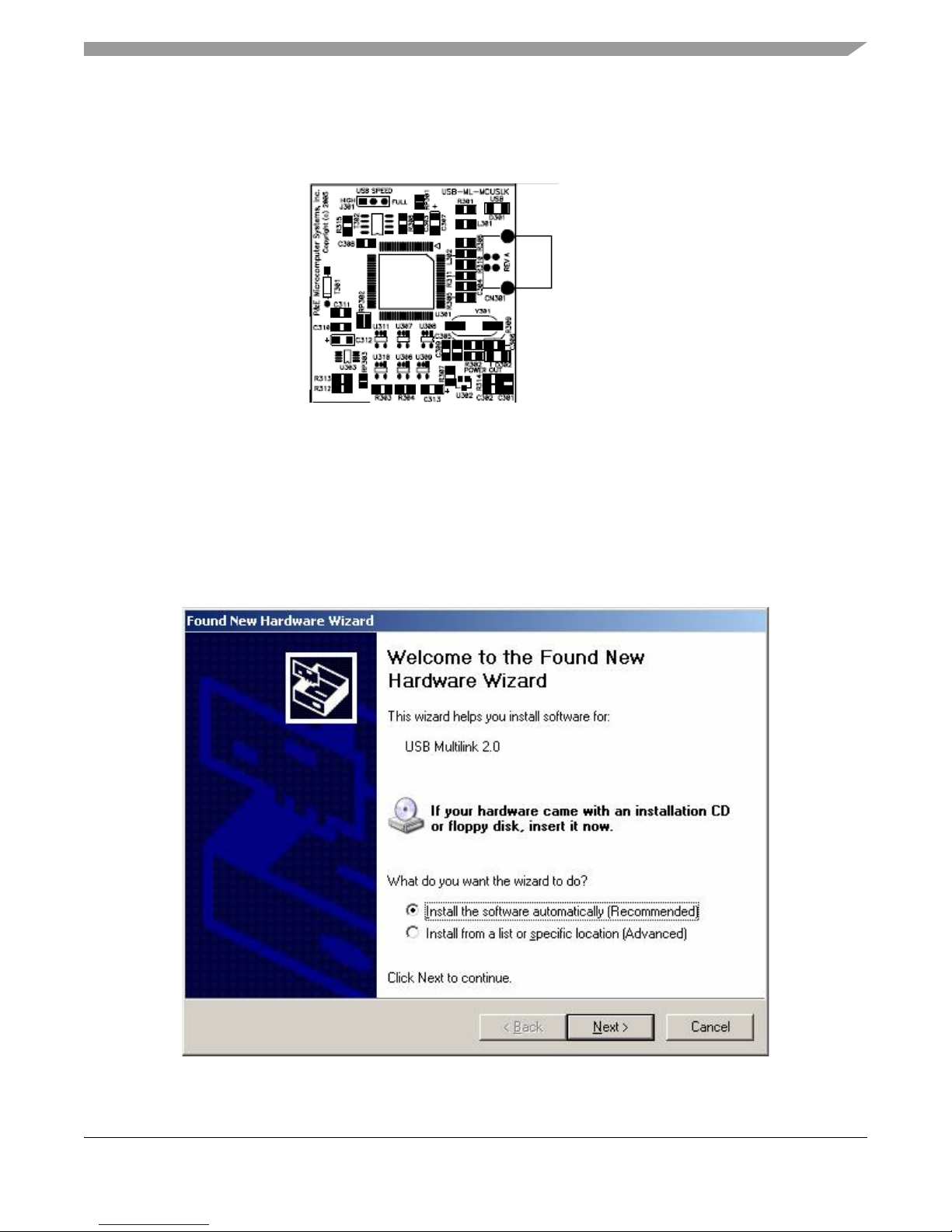
7. Connect the other end of the USB cable to the USB connector on the MCU Project Board – 2.
Figure 3 illustrates the USB connector on the project board for the BDM Multilink pod interface to
power, program, erase, and debug the MC9S12C32 MCU on the application module board.
PLUG-IN
USB
CABLE
Figure 3. Installation of USB Cable
NOTE
Steps 8 through 11 are a one-time, required procedure per host PC that you
intend to use with the MCU Project Board – 2 and can be skipped on
subsequent uses of your project board.
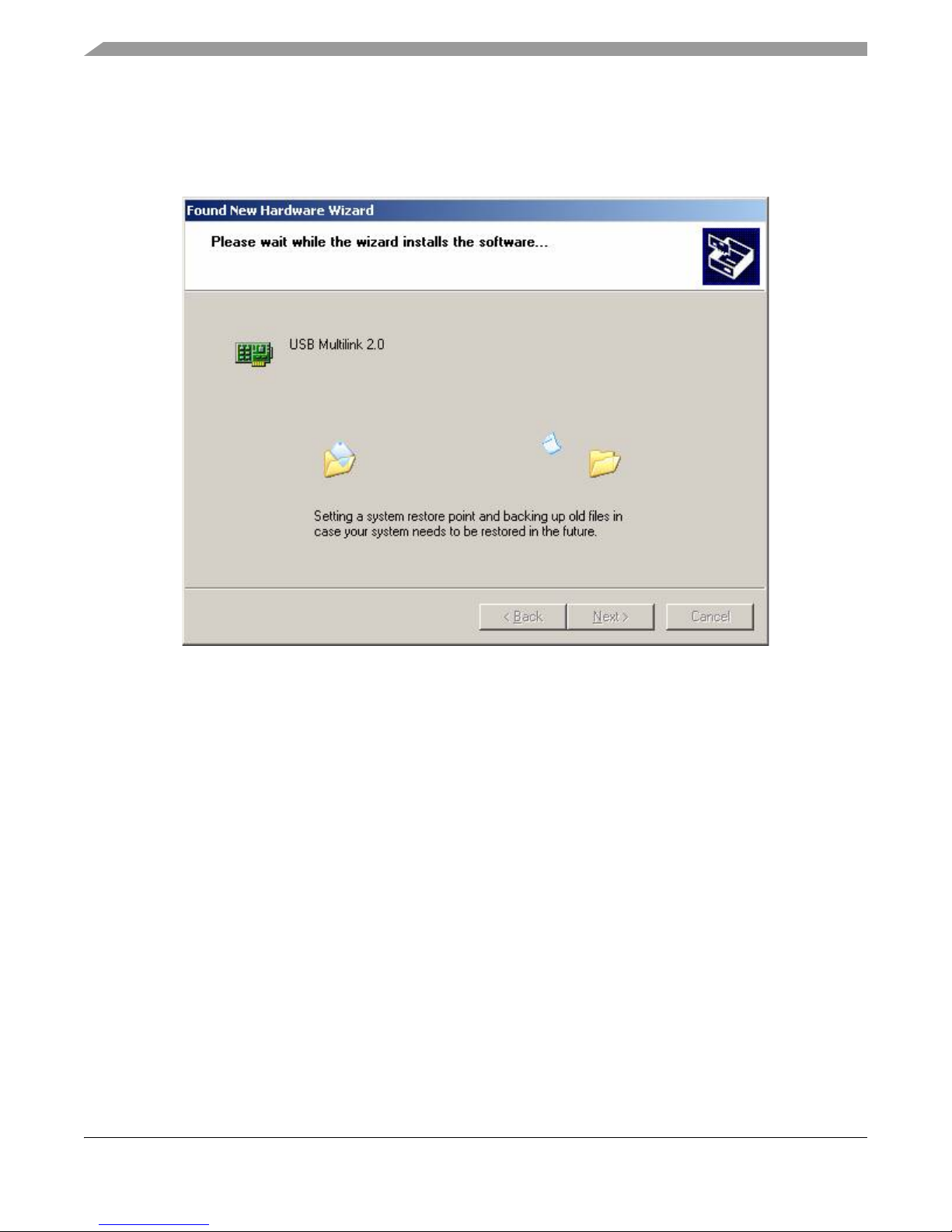
8. Allow your host PC to detect your new hardware. You will see a popup message in the task bar
stating, “Found New Hardware.” Without any user action, the Found New Hardware Wizard will
appear as illustrated by Figure 4 and prompt you to install software for USB Multilink 2.0.
Figure 4. Found New Hardware Wizard (Screen 1)
Getting Started with the MCUSLK for MC9S12C32 Application Module, Rev. 0
Freescale Semiconductor 7
Page 8
Hardware Setup
9. Select “Install the software automatically (recommended)” from the Found New Hardware Wizard
(Screen 1) and click “Next” button to continue with installation.
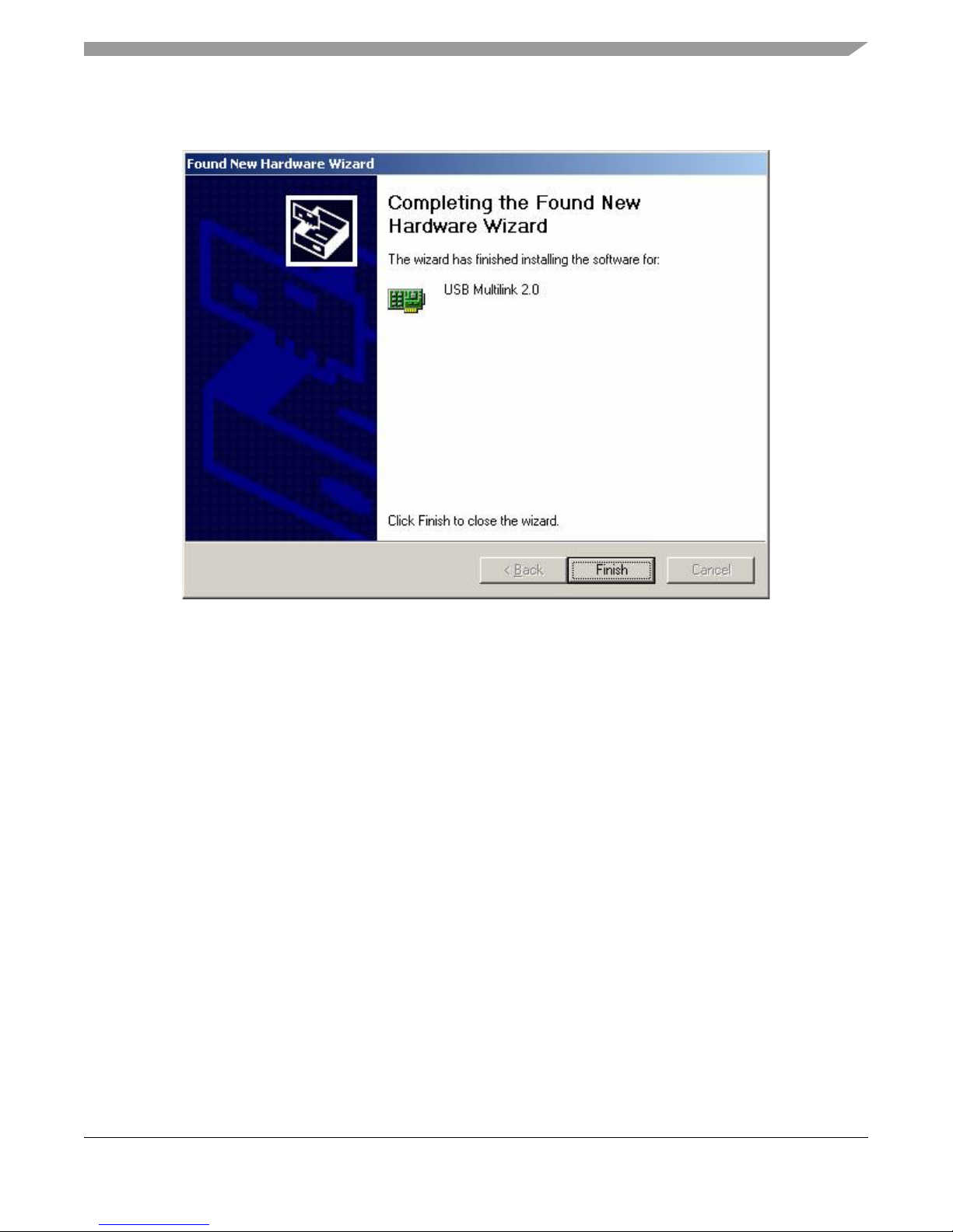
10. Installation will begin with the Found New Hardware Wizard (Screen 2) illustrated by Figure 5. No
user action necessary until software is completed installing.
Figure 5. Found New Hardware Wizard (Screen 2)
Getting Started with the MCUSLK for MC9S12C32 Application Module, Rev. 0
8 Freescale Semiconductor
Page 9
Hardware Setup
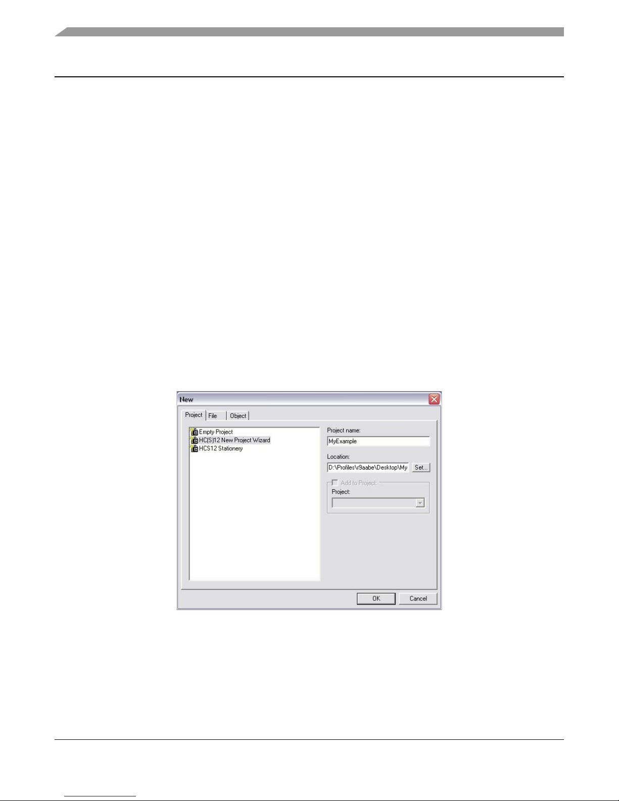
11. Successful installation is verified by Found New Hardware (Screen 3) illustrated by Figure 6. Click
on “Finish” button to complete installation and close wizard.
Figure 6. Found New Hardware Wizard (Screen 3)
12. Verify that the +3.3 V LED, +5 V LED, and both green and yellow USB LEDs on the MCU Project
Board – 2 are lit.
13. Verify that the V
LED on the MC9S12C32 MCU application module board (CSM12C32) is lit.
DD
14. If the LEDs in steps 13 and 14 are not lit, make sure the jumper options are set as described in
steps 2 through 6. Also, see the troubleshooting tips section in the MCU Project Board – 2 user
guide.
15. The MCU Project Board – 2 and the MC9S12C32 MCU application module are now ready for use.
Getting Started with the MCUSLK for MC9S12C32 Application Module, Rev. 0
Freescale Semiconductor 9
Page 10
Development
Development
Creating and Building a Project in CodeWarrior Environment
After properly installing and registering the CodeWarrior development tools as described in the Software
Setup section, and completing the MCU Project Board – 2 configuration as described in the Hardware
Setup section, you can now begin to develop your application for a target microcontroller. This section will
create and build a project under the CodeWarrior for HC(S)12 development tool platform.
NOTE
The instructions below are slightly different from the steps described in the
quick start pamphlet included in the CodeWarrior for HC(S)12 development
tools CD case. The instructions below are adjusted for the MCUSLK and
MC9S12C32 development module.
1. Launch the CodeWarrior IDE
a. Select: Start > Programs > Metrowerks CodeWarrior > CW12 V3.1; a menu
will appear
b. Select: CodeWarrior IDE; IDE will start and a CodeWarrior window will appear
2. Create a new project
a. From IDE main menu bar, select: File> New; a new window will appear (see Figure 7)
Figure 7. New Window
b. Select: “HC(S)12 New Project Wizard”
c. In the “Project name” text box, type the name you want to give the project (IDE automatically
adds .mcp extension when it creates project)
d. In the “Location” text box, set location where you want the project to be created
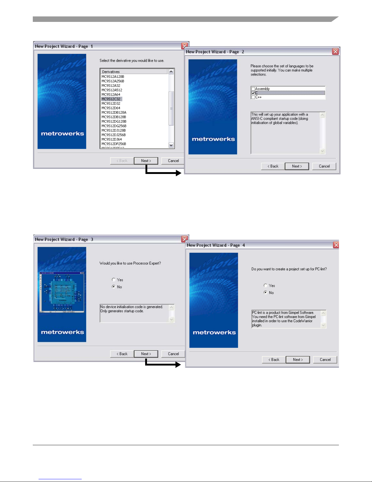
e. Click “OK” — the first page of the new project wizard will appear (see Figure 8a)
Getting Started with the MCUSLK for MC9S12C32 Application Module, Rev. 0
10 Freescale Semiconductor
Page 11
Development
a
b
Figure 8. New Project Wizard — Page 1 and Page 2
f. Select “MC9S12C32”
g. Click “Next” — Page 2 of the new project wizard will appear (see Figure 8b)
h. Make sure “C” checkbox is marked (if using assembly or C++, mark the respective selection)
i. Click “Next” — Page 3 of the new project wizard will appear (see Figure 9a)
a
Figure 9. New Project Wizard — Page 3 and Page 4
j. Select “No”, you do not want your project configured with Processor Expert
k. Click “Next” — Page 4 of the new project wizard will appear (see Figure 9b)
l. Select “No”, you do not want your project configured to work with PC-lint
m. Click “Next” — Page 5 of the new project wizard will appear (see Figure 10a)
Getting Started with the MCUSLK for MC9S12C32 Application Module, Rev. 0
Freescale Semiconductor 11
b
Page 12
Development
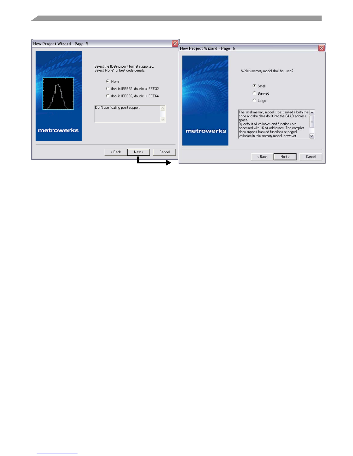
n. Select “None”, you do not want to specify a floating point format
o. Click “Next” — Page 6 of the new project wizard will appear (see Figure 10b)
p. Select “Small” memory model
q. Click “Next” — Page 7 of the new project wizard will appear (see Figure 11)
a
b
Figure 10. New Project Wizard — Page 5 and Page 6
Getting Started with the MCUSLK for MC9S12C32 Application Module, Rev. 0
12 Freescale Semiconductor
Page 13
Development
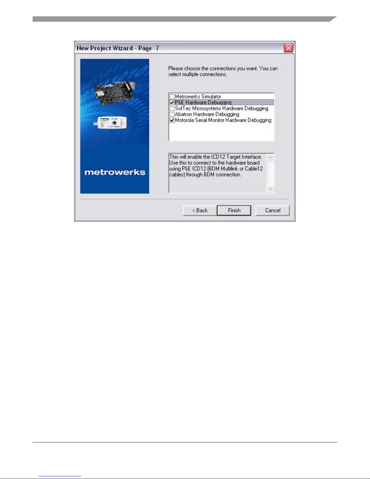
Figure 11. New Project Wizard — Page 7
r. Page 7 allows you to specify connections that the project should be configured to support.
Select “P&E Hardware Debugging” and “Motorola Serial Monitor Hardware Debugging”
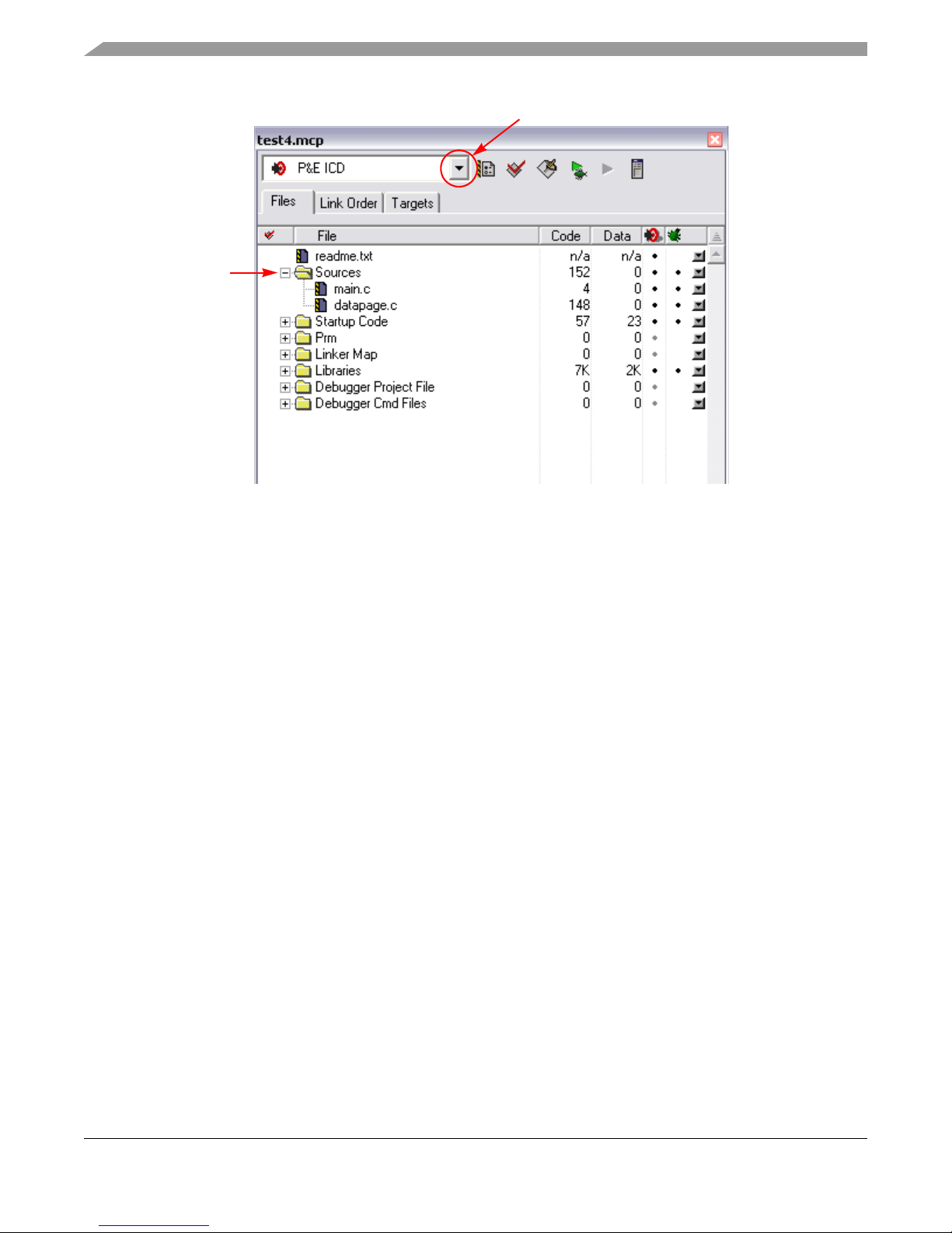
s. Click “Finish” — the wizard creates a new project based on information you specified. A project
window will appear, docked at left side of main window (see Figure 12)
Getting Started with the MCUSLK for MC9S12C32 Application Module, Rev. 0
Freescale Semiconductor 13
Page 14
Development
Drop-Down Menu
Figure 12. Project Window
NOTE
To undock the project window, double-click the docking handle (double
gray lines at top of the project window). To re-dock window, right click in title
bar of project window, and select “docked”.
3. Select build target
Your project can contain multiple build targets. For this example, we use the P&E ICD target, which
uses the USB BDM pod on the MCU Project Board – 2. This BDM pod provides bidirectional
communication between the microcontroller and the debugger.
a. Click the drop-down menu of the project window (see Figure 12)
b. Select “P&E ICD”
4. Edit source code
a. Click the “+” sign next to the “sources” folder to reveal files (see Figure 12)
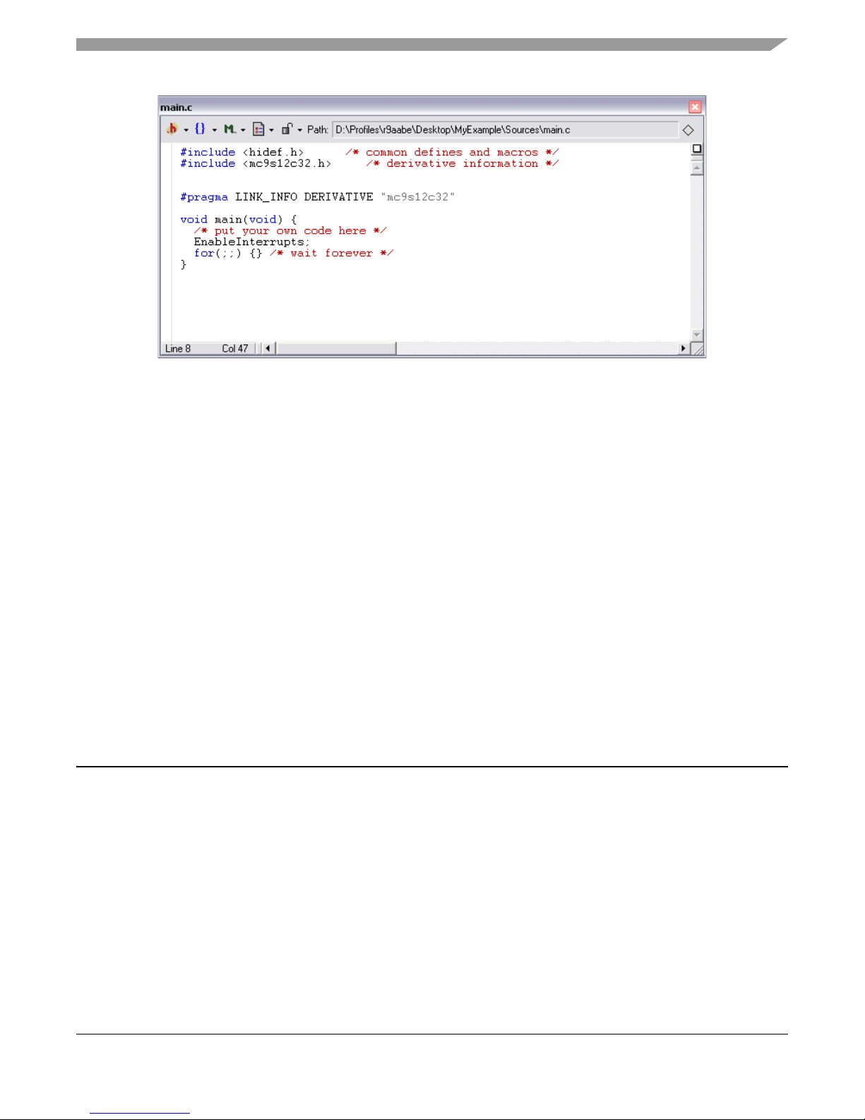
b. Double-click the main.c file; an editor window will open and display the contents of main.c
Getting Started with the MCUSLK for MC9S12C32 Application Module, Rev. 0
14 Freescale Semiconductor
Page 15
Debugging your Application
Figure 13. main.c in Editor Window
c. Make changes to the contents of main.c file, if desired
d. If you make changes to main.c, from IDE main menu bar, select File> Save
5. Add files (if appropriate)
a. Highlight the “sources” folder
b. From the IDE main menu bar, select “project”; a menu will appear
c. Select “add files”; a dialog box will appear
d. Navigate to that directory that contains the file you want to add
e. Highlight the filename of the file you want to add to your project
f. Click “open”; the “add files” dialog box will appear
g. Check the checkbox for each build target to which the file applies
h. Click “OK”; the “add files” dialog box closes. In the “project” window, the filename of added file
will appear under the “sources” folder
6. Build project
a. From IDE main menu bar, select “project”
b. Select “make”; IDE builds (assembles, compiles, and links) project; error and warnings window
will open and show error messages and warning messages, if appropriate
Debugging your Application
The following steps explain how to establish communication and upload your application software to the
MC9S12C32 MCU application module (CSM-12C32). This will allow you to debug your application
through Metrowerks’ True-Time Simulator & Real-Time Debugger using the BDM pod interface on the
MCU Project Board – 2. The Software Setup and Hardware Setup sections must be completed before
executing the steps in this section.
1. Make sure power is applied to the project board. If not, go back and follow hardware setup section
instructions.
2. Start debugger
Getting Started with the MCUSLK for MC9S12C32 Application Module, Rev. 0
Freescale Semiconductor 15
Page 16
Debugging your Application
a. From the main menu bar in CodeWarrior IDE, select “project”
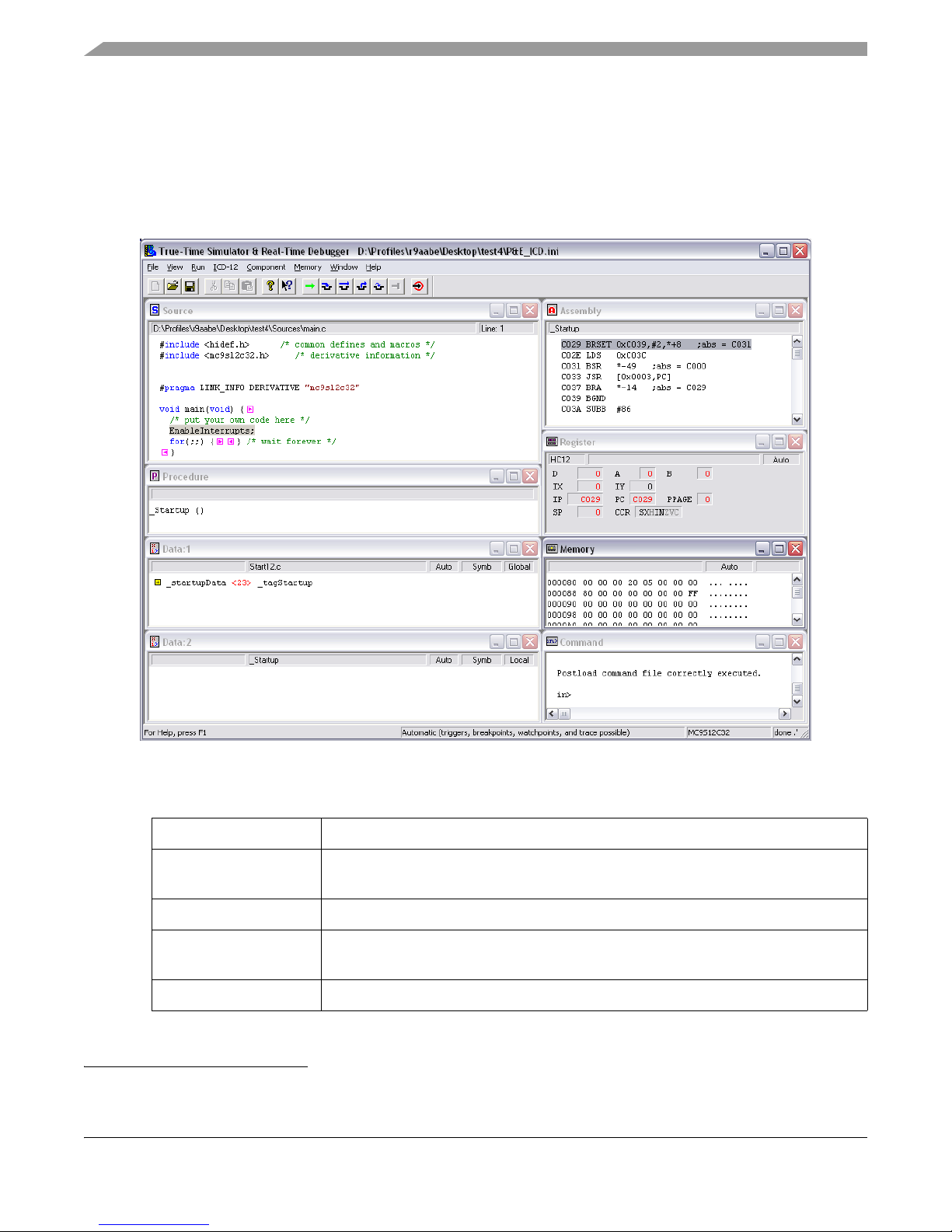
b. Select “debug”; Debugger window will open in ICD-12 target
If prompted by debugger with a communication setup window, select the
appropriate host PC USB port being used by the BDM pod and click “OK”.
NOTE
Figure 14
. Debugger Window
1
Table 2. Debugger Windows
Window Name Description
Source and
Assembly
Register Displays the MCU internal registers
Memory
Procedure Displays the active procedure being evaluated
1. For a description of debugger windows, see Table 2
Getting Started with the MCUSLK for MC9S12C32 Application Module, Rev. 0
16 Freescale Semiconductor
Display programmed application software in C and assembly programming
languages, respectively
Displays the active value at each memory address in the MCU internal
memory map
Page 17
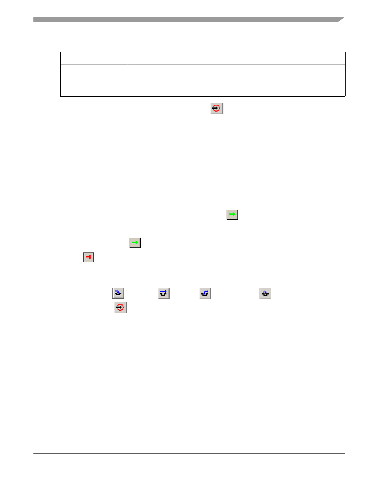
Table 2. Debugger Windows
Window Name Description
Debugging your Application
Data 1 and
Data 2
Command Allows user control and logs commands executed
Display any global or local variables in your application software and their
active value
3. Reset the target by clicking on the reset target icon, .
4. Right-click on “source” window and select “open source file”; “Source files” menu will appear. To
view between source files in your application software, select the appropriate file in the menu, then
click “OK”
5. Right-click on executable line of source code in “source” window to set breakpoints or triggers in
program code
6. Run application
a. From debugger main menu, select “run”; “Run” menu will appear
b. Select “Start/continue”; program will execute until encountering first breakpoint (if breakpoint
is present); Command pane displays program status
NOTE
Alternatively, you can click on start/continue icon in the debugger
taskbar
7. Click start/continue icon,
, to resume program code execution (if breakpoint occurred) or click
halt icon, , to stop program execution
NOTE
The debugger taskbar includes other icons for debugging which allow
single step , step over , step out , assembly step , and
reset target functions.
8. In the debugger window tool bar, select: File> Exit (to exit debugger)
9. In the IDE main window tool bar, select: File> Exit (to exit CodeWarrior IDE)
Congratulations! You have successfully developed a project using Metrowerks CodeWarrior development
tools and your MCUSLK!
Getting Started with the MCUSLK for MC9S12C32 Application Module, Rev. 0
Freescale Semiconductor 17
Page 18

How to Reach Us:
USA/Europe/Locations not listed:
Freescale Semiconductor Literature Distribution
P.O. Box 5405, Denver, Colorado 80217
1-800-521-6274 or 480-768-2130
Japan:
Freescale Semiconductor Japan Ltd.
SPS, Technical Information Center
3-20-1, Minami-Azabu
Minato-ku
Tokyo 106-8573, Japan
81-3-3440-3569
Asia/Pacific:
Freescale Semiconductor H.K. Ltd.
2 Dai King Street
Tai Po Industrial Estate
Tai Po, N.T. Hong Kong
852-26668334
Learn More:
For more information about Freescale
Semiconductor products, please visit
http://www.freescale.com
Information in this document is provided solely to enable system and software implementers to use
Freescale Semiconductor products. There are no express or implied copyright licenses granted
hereunder to design or fabricate any integrated circuits or integrated circuits based on the information
in this document.
Freescale Semiconductor reserves the right to make changes without further notice to any products
herein. Freescale Semiconductor makes no warranty, representation or guarantee regarding the
suitability of its products for any particular purpose, nor does Freescale Semiconductor assume any
liability arising out of the application or use of any product or circuit, and specifically disclaims any
and all liability, including without limitation consequential or incidental damages. “Typical” parameters
which may be provided in Freescale Semiconductor data sheets and/or specifications can and do
vary in different applications and actual performance may vary over time. All operating parameters,
including “Typicals” must be validated for each customer application by customer’s technical experts.
Freescale Semiconductor does not convey any license under its patent rights nor the rights of others.
Freescale Semiconductor products are not designed, intended, or authorized for use as components
in systems intended for surgical implant into the body, or other applications intended to support or
sustain life, or for any other application in which the failure of the Freescale Semiconductor product
could create a situation where personal injury or death may occur. Should Buyer purchase or use
Freescale Semiconductor products for any such unintended or unauthorized application, Buyer shall
indemnify and hold Freescale Semiconductor and its officers, employees, subsidiaries, affiliates, and
distributors harmless against all claims, costs, damages, and expenses, and reasonable attorney
fees arising out of, directly or indirectly, any claim of personal injury or death associated with such
unintended or unauthorized use, even if such claim alleges that Freescale Semiconductor was
negligent regarding the design or manufacture of the part.
Freescale™ and the Freescale logo are trademarks of Freescale Semiconductor, Inc. All other
product or service names are the property of their respective owners.
© Freescale Semiconductor, Inc. 2004.
MCUSLK_CSM12C32
Rev. 0, 6/2005
 Loading...