

Page 1

TCP/IP Applications Using the
MCF51CN Family—Designer Reference
Manual
Device Supported: MCF51CN Microcontrollers
Document Number: DRM114
Rev. 0, 12/2009
Page 2

TCP/IP Applications Using the MCF51CN Family—Designer Reference Manual, Rev. 0, 12/2009
Freescale Semiconductor2
Page 3

Contents
PageTitleSection Number
Chapter 1
Introduction
Overview...........................................................................................................................................................................51.1
Key Features.....................................................................................................................................................................51.2
Advantages........................................................................................................................................................................81.3
Development Tools...........................................................................................................................................................81.4
Top and Bottom View of the MCF51CN128 Reference Design Hardware......................................................................81.5
How the MCF51CN128 Reference Design Fits Your System..........................................................................................91.6
Chapter 2
Hardware Description
Hardware.........................................................................................................................................................................132.1
Minimal System Features...............................................................................................................................................132.2
Demo System Features...................................................................................................................................................142.3
Connection Between Minimal System and Demo System Features...............................................................................152.4
Hardware Block Diagram...............................................................................................................................................162.5
Pinout Description..........................................................................................................................................................182.6
MCF51CN128 Reference Design Board Power Options...............................................................................................192.7
Hardware Considerations................................................................................................................................................202.8
Chapter 3
Firmware Description
Firmware.........................................................................................................................................................................213.1
Firmware Organization...................................................................................................................................................213.2
Block Diagram................................................................................................................................................................223.3
System Startup................................................................................................................................................................233.4
Internal Functionality of Socket Layer...........................................................................................................................243.5
Chapter 4
System Setup
Getting Started................................................................................................................................................................274.1
TCP/IP Applications Using the MCF51CN Family—Designer Reference Manual, Rev. 0, 12/2009
3Freescale Semiconductor
Page 4

PageTitleSection Number
Install Software...............................................................................................................................................................274.2
Hardware Setup...............................................................................................................................................................274.3
HTTP Server Functionality.........................................................................................................................284.3.1
Email Client Functionality..........................................................................................................................314.3.2
FTP Server Functionality.............................................................................................................................324.3.3
Serial Bridge Functionality..........................................................................................................................344.3.4
Principle of Operation.....................................................................................................................................................354.4
Serial Configuration Commands....................................................................................................................................364.5
Support............................................................................................................................................................................394.6
Appendix A
Additional Files...............................................................................................................................................................41A.1
Appendix B
Bill of Materials (BOM).................................................................................................................................................43B.1
Appendix C
Schematics......................................................................................................................................................................47C.1
TCP/IP Applications Using the MCF51CN Family—Designer Reference Manual, Rev. 0, 12/2009
Freescale Semiconductor4
Page 5

Chapter 1
Introduction
1.1 Overview
This reference manual describes using the MCF51CN128 reference design hardware
to run the following TCP/IP applications:
• SCI/SPI to Ethernet
• Web Server
• Email Client
• FTP Server
All hardware schematics diagram, gerber files, Allegro hardware source files, board pictures,
and firmware source codes are available in reference materials. All hardware files and
software can be reused to enable directly TCP/IP connectivity in customized applications.
For details about the technical implementation of the reference design main features, refer
to the following documents:
• Application note titled Serial-to-Ethernet Bridge Using MCF51CN Family and
FreeRTOS (document AN3906)
• Application note titled W eb Server Using MCF51CN Family and F r eeRTOS (document
AN3928)
• Application note titled Email Client Using MCF51CN F amily and F reeRT OS (document
AN3930)
• Application note titled FTP Server Using MCF51CN F amily and F reeRT OS (document
AN3931)
1.2 Key Features
•
Uses Freescale ColdFire V1 Core MCF51CN128 48-pin QFN package running up
to 50.33 MHz
TCP/IP Applications Using the MCF51CN Family—Designer Reference Manual, Rev. 0, 12/2009
5Freescale Semiconductor
Page 6

• Low cost board in a minimal size of 2.89’’ × 1.55’’. Ethernet Minimal System is 1.15’’
× 1.55’’.
• For the MCF51CN128 reference design hardware, po wer can be applied to both unused
pairs from the RJ45 cable. Therefore, power through the jack is not required. F or more
details go to Section 2.7.
• The following TCP/IP services are implemented.
DHCP Client Service:•
IP dynamic address (DHCP) or static support at runtime•
• Serial Bridge
A UART or SPI to Ethernet bridge is implemented using the socket approach.•
• Supports client or server implementation that allows connecting two serial
bridges using the Internet.
• An always enabled web page can configure all interfaces and bridge settings.
A reset command can be sent through the web page to make settings take effect.
• The following settings can be changed or shown at runtime through the
configuration web page or at compile time:
• MAC address
• IP address
• IP mask address
• IP gateway address
• Server address to connect as a client
• Static or dynamic IP address
• TCP port to connect or bind to
• TCP client or server implementation
• Configuration or bridge implementation
• UART port
• UART baudrate
• UART parity
• UART number of bits
• UART number of stop bits
TCP/IP Applications Using the MCF51CN Family—Designer Reference Manual, Rev. 0, 12/2009
Freescale Semiconductor6
Key Features
Page 7

• UART flow control
• SPI port
• SPI baudrate
• SPI polarity
• SPI phase
• SPI master or slave
• SPI polling or interrupt handling
• Using hardware and software flow control for the RS232 interface
• Presence of RS485 transceiver and connector
• The bridge can be configured through the UART interface using a set of
commands explained in Section 4.5
• For the MCF51CN128 reference design hardware, po wer can be applied to pin
6 of the UART connector. Therefore, the power jack is not required. Refer to
Figure 2-5 for more details.
• An accelerometer by SPI is on-board to test SPI bridge.
• HTTP Server Service
• Supports HTTP with the following services:
• HTTP 2.0—Persistent connections or keep-alive sessions
• SSI—Server side include (SSI) directives
• AJAX—Used to give the illusion that a web page changes without
refreshing it
• FORMS (POST request)
• CGI—(POST request) common gateway interface support
• Tasks status though a web page
• Email Client Service
• Assigned IP is sent via email if the dynamic IP is used.
TCP/IP Applications Using the MCF51CN Family—Designer Reference Manual, Rev. 0, 12/2009
7Freescale Semiconductor
Chapter 1 Introduction
Page 8

• FTP Server Service
• Stores information using FAT and then makes it accessible using FTP
• FTP is mounted over an SD card reader
1.3 Advantages
•
The MCF51CN128 is a low cost MCU that can enable Ethernet/TCP/IP connecti vity
to any embedded design.
• Software source codes are available to directly use in a customer application. It also
allows customer changes or customizations.
• Hardware files are provided for free. If a change in hardware is required for a customized
design, hardware source files can be edited.
• The MCF51CN128 MCU can obtain power from connectors like the RJ45 and DB9.
• For support enter a service request at, www.freescale.com/support.
1.4 Development Tools
•
CodeWarrior V6.2.1 is used to download the software application.
• A proper Ethernet cable must be selected depending on the Ethernet element that is the
PC, hub, switch, or router.
1.5 T op and Bottom View of the MCF51CN128 Reference Design
Hardware
The following figures describe the top and bottom view of the board. A hardware block
diagram is shown in Figure 2-2. For details about components, go to Sections 2.2 and Section
2.3.
TCP/IP Applications Using the MCF51CN Family—Designer Reference Manual, Rev. 0, 12/2009
Freescale Semiconductor8
Advantages
Page 9
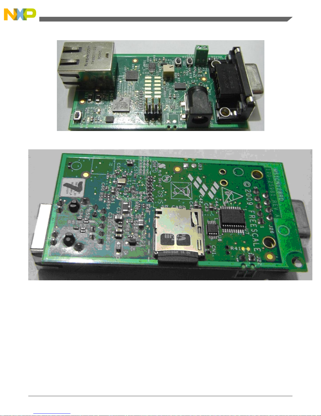
Figure 1-1.Top view of MCF51CN128 reference design hardware
Figure 1-2. Bottom view of MCF51CN128 reference design hardware
1.6 How the MCF51CN128 Reference Design Fits Your System
The following figures show how the system fits into some TPC/IP applications. Specific
features are explained in the Section Firmware. The figures show reference design squared
by a red box.
TCP/IP Applications Using the MCF51CN Family—Designer Reference Manual, Rev. 0, 12/2009
9Freescale Semiconductor
Chapter 1 Introduction
Page 10
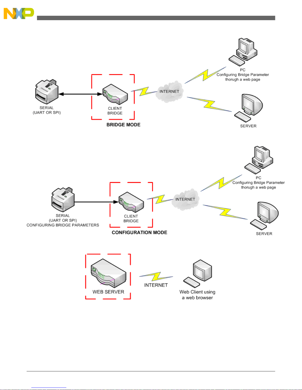
Figure 1-3. Serial bridge in Bridge mode
Figure 1-4. Serial bridge in Configuration mode
Figure 1-5.Web server implemented at MCF51CN family providing HTTP services, one
client at a time
TCP/IP Applications Using the MCF51CN Family—Designer Reference Manual, Rev. 0, 12/2009
Freescale Semiconductor10
How the MCF51CN128 Reference Design Fits Your System
Page 11
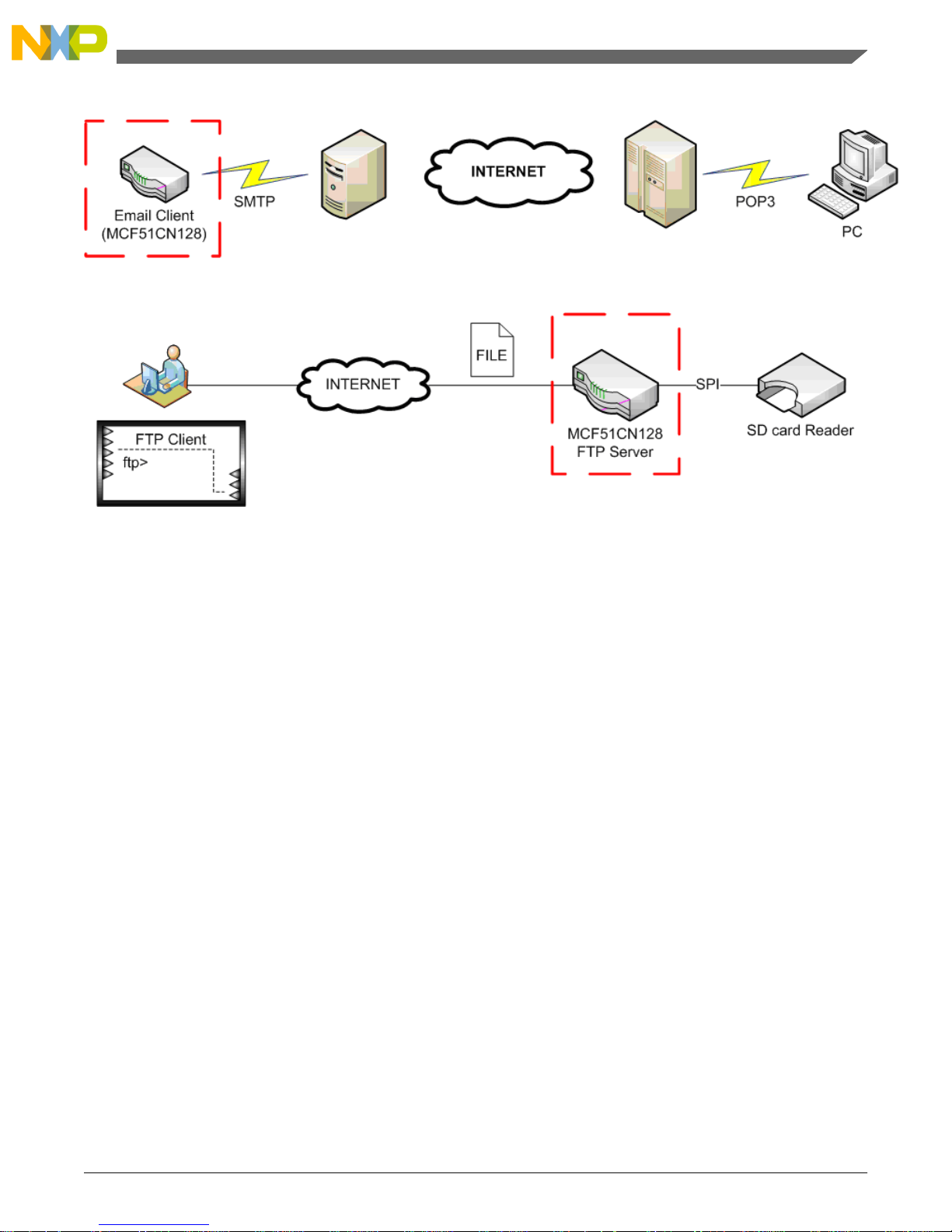
Figure 1-6. Email client connecting to an SMTP server
Figure 1-7. FTP server using FAT16 on an SD card
TCP/IP Applications Using the MCF51CN Family—Designer Reference Manual, Rev. 0, 12/2009
11Freescale Semiconductor
Chapter 1 Introduction
Page 12

TCP/IP Applications Using the MCF51CN Family—Designer Reference Manual, Rev. 0, 12/2009
Freescale Semiconductor12
How the MCF51CN128 Reference Design Fits Your System
Page 13

Chapter 2
Hardware Description
2.1 Hardware
The hardware design characteristics are as follows:
1. Show the small-size Ethernet application board using the MCF51CN128 MCU—This
area must be programmable, functional, and completely independent. This area is called
the Minimal System (see Section 2.4).
2. Demonstrate the Minimal System capabilities using sensors and external hardware.
This area is called the Demo System (see Section 2.4).
3. The Minimal System must be designed in the hardware in such a way that the whole
system can work independent of the Demo System. A set of zero—Resistors are provided
so the Minimal System can be isolated from the Demo System.
4. Provide the user with customizable hardware—If only the Minimal System is required,
layout files from the MCF51CN128 reference design can be edited. Therefore, the
Minimal System can be copied to a new hardware project. Only a power source
connection is required for the Minimal System.
5. To reuse the Minimal System, the same hardware components must be selected.
6. The Demo System must be able to provide all the serial interfaces for testing the VSCI,
IIC, and SPI.
7. The board is able to get power from five sources. See Section 2.7.
8. The board is able to provide all serial signals av ailable to the client through an accessible
serial header.
2.2 Minimal System Features
The following is a list of main components in the Minimal system:
TCP/IP Applications Using the MCF51CN Family—Designer Reference Manual, Rev. 0, 12/2009
13Freescale Semiconductor
Page 14

• Top view (see Figure 1-1):
MCF51CN128 —Uses a 48-pin QFN package to handle all the TCP/IP applications•
• Power LED—Turned on when the power is applied
• Reset button—Resets the MCF51CN128 processor
• Customized BDM for programming
• LDO on-board—Provides regulated 3.3 V. The voltage must be between 3.7 V and
5.5 V.
• Ethernet PHY 10/100 Mbps
• RJ45 connector
• Bottom view (see Figure 1-2):
• A single 25 MHz oscillator crystal—Feeds the MCF51CN128. The MCU then
feeds the Ethernet PHY clock.
2.3 Demo System Features
The following is the list of the Demo system main components:
• Top view (see Figure 1-1):
Standard 2 × 3 BDM connector•
• Serial header—All serial signals are mapped
• Temperature sensor by IIC
• ADC—Using a POT
• LED—General purpose LED
• Power can be supplied from:
Power jack—5.5 V max•
• Terminal block—5.5 V max
• Unused DB9 pin for power—5.5 V max
• Unused Ethernet cable pairs for power—5.5 V max
• Battery—3.3 V max
• Accelerometer sensor using SPI
TCP/IP Applications Using the MCF51CN Family—Designer Reference Manual, Rev. 0, 12/2009
Freescale Semiconductor14
Demo System Features
Page 15
• Two buttons connected to KBI pins
• RS485 output connector
• Female DB9 output connector
• Bottom view (see Figure 1-2):
• RS485 transceiver
• RS232 transceiver
• µSD card connector
2.4 Connection Between Minimal System and Demo System
Features
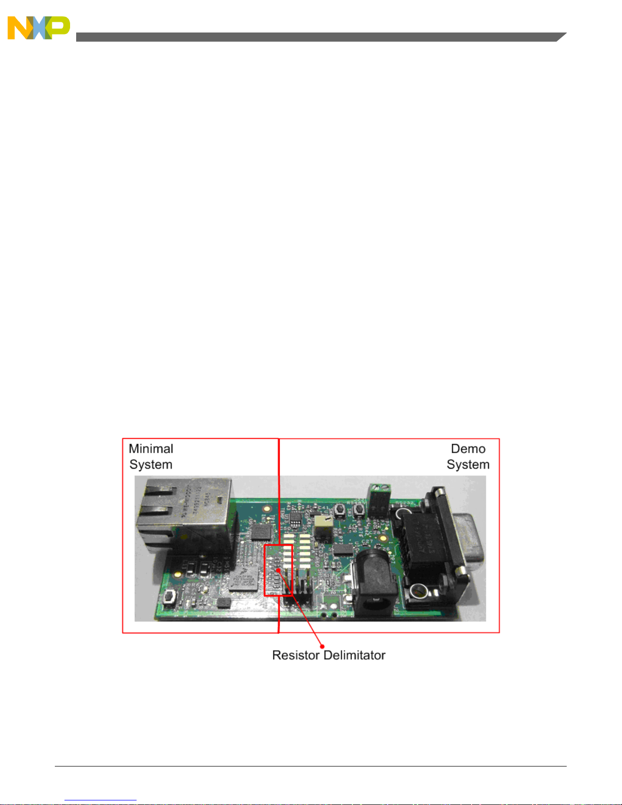
The following figure shows how the MCF51CN128 reference design hardware is divided
into a Minimal and Demo system.
A set of zero Ω resistors that connect both these systems are present and visible at the top
and bottom layers on the MCF51CN128 reference design hardware. Disconnecting these
registers isolate the Minimal system from the Demo system.
Figure 2-1. Board showing Minimal and Demo system
TCP/IP Applications Using the MCF51CN Family—Designer Reference Manual, Rev. 0, 12/2009
15Freescale Semiconductor
Chapter 2 Hardware Description
Page 16
2.5 Hardware Block Diagram
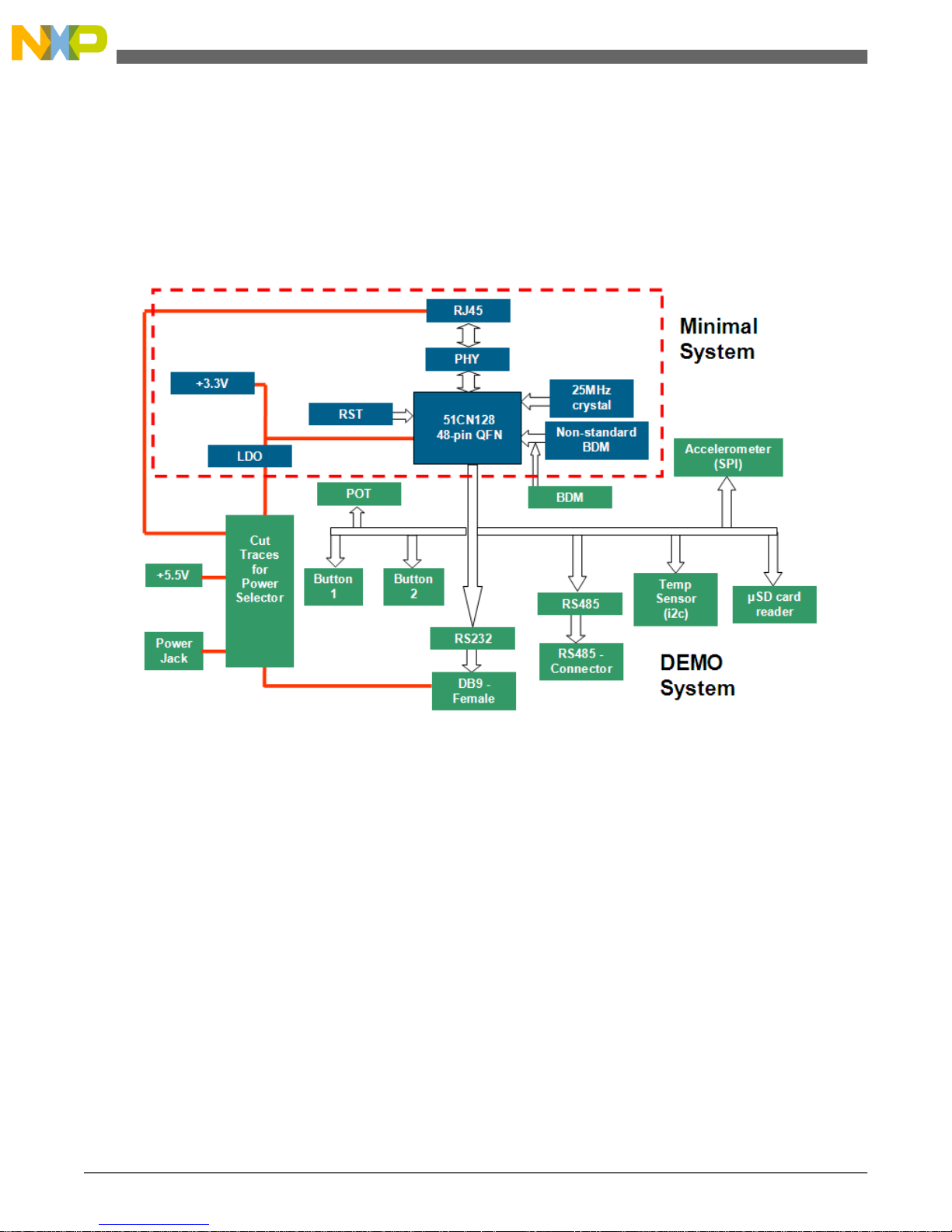
The following block diagram shows the features of the MCF51CN128 reference design
hardware. The components related to the Minimal System are shown in the color blue and
the components related to the Demo System are shown in the color green.
Figure 2-2. MCF51CN128 reference design hardware block diagram
The following figures sho w the main hardware components on the MCF51CN128 reference
design hardware.
TCP/IP Applications Using the MCF51CN Family—Designer Reference Manual, Rev. 0, 12/2009
Freescale Semiconductor16
Hardware Block Diagram
Page 17
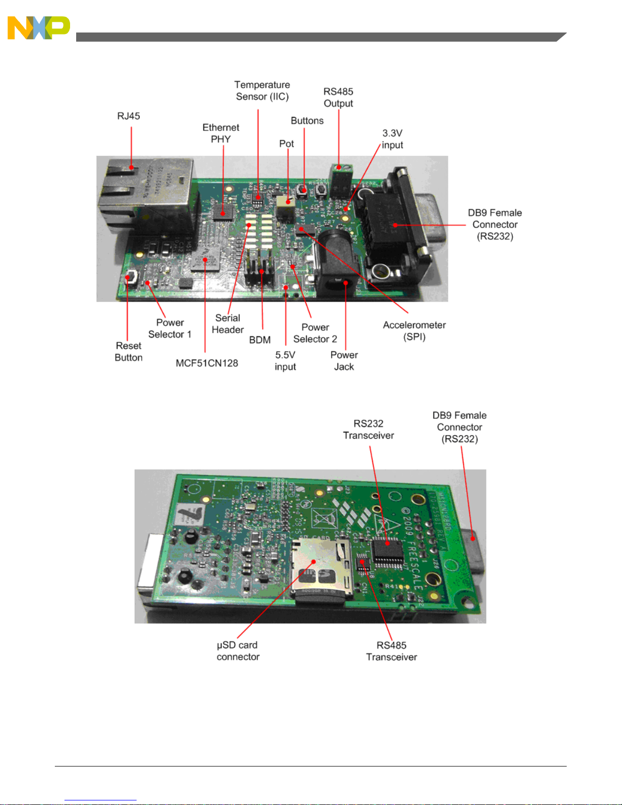
Figure 2-3. MCF51CN128 reference design top view
Figure 2-4. MCF51CN128 reference design bottom view
Note
The serial header is not populated in Figure 2-3.
TCP/IP Applications Using the MCF51CN Family—Designer Reference Manual, Rev. 0, 12/2009
17Freescale Semiconductor
Chapter 2 Hardware Description
Page 18
2.6 Pinout Description
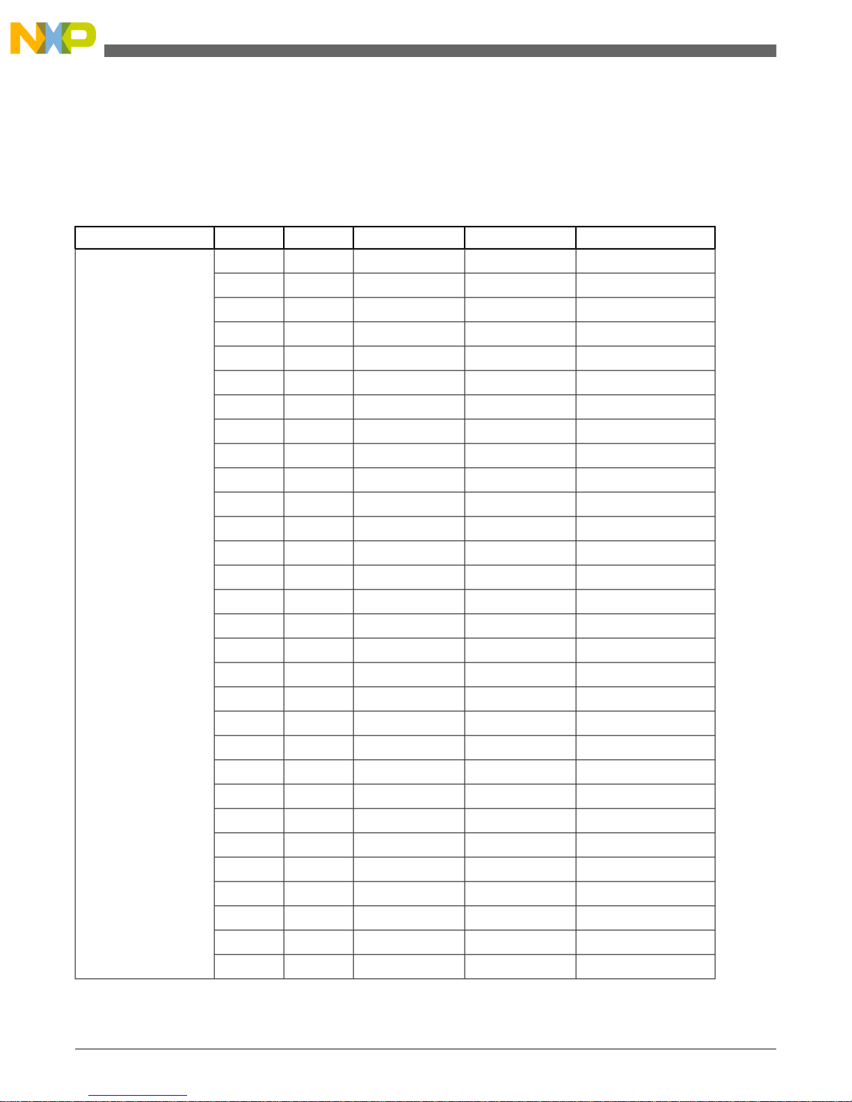
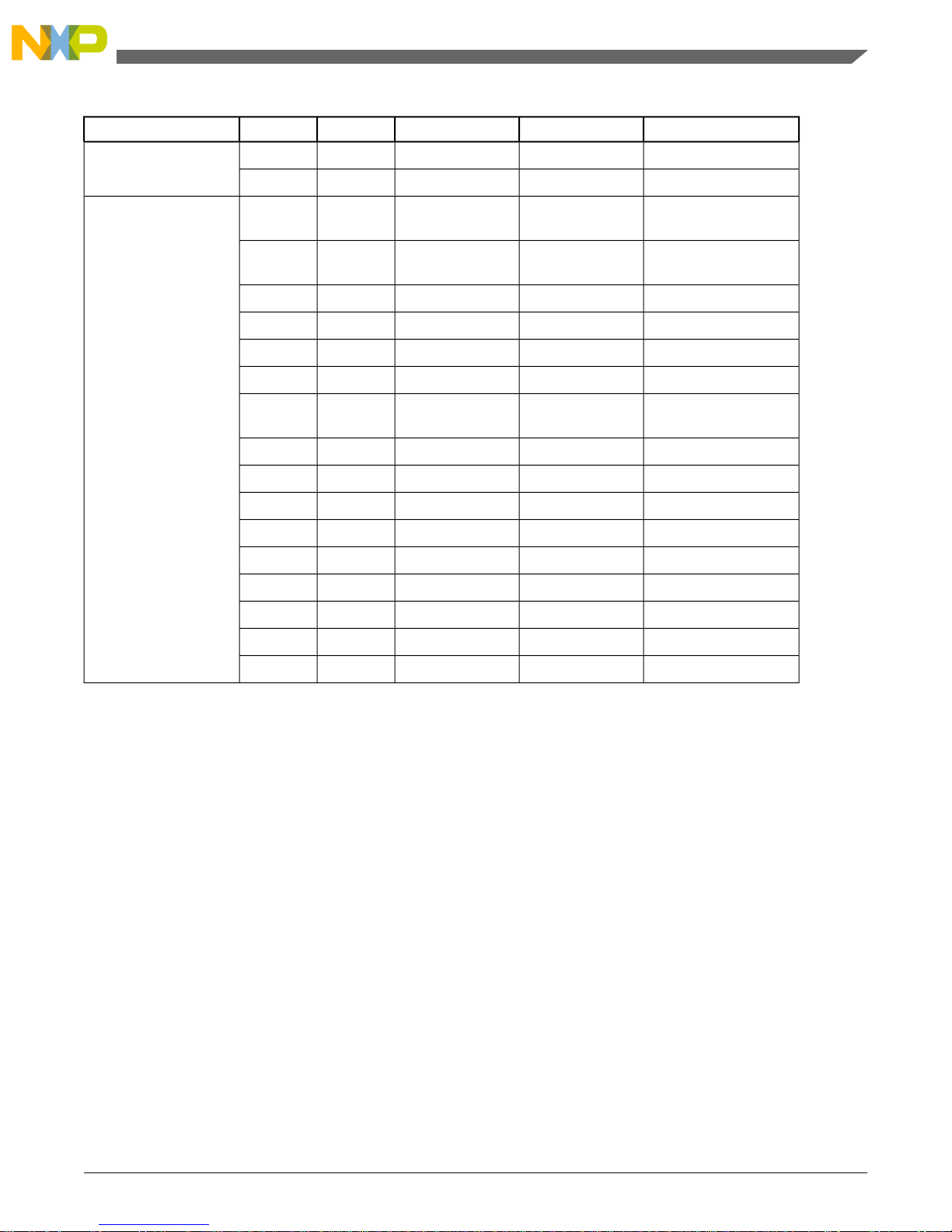
The following list sho ws how all the pins of the MCF51CN128 48-pin QFN are used
on the hardware:
Table 2-1. MCF51CN128 reference design hardware pin assignment
NotesFunc 2Func 1NamePin
VDD11Minimal System
VSS12
VDD213
VSS214
VDD325
VDDA26
VSSA27
VSSA28
VDD437
VSS438
PHYCLKPTA03
MII_MDIOPTA14
MII_MDCPTA25
MII_RXD3PTA36
MII_RXD2PTA47
MII_RXD1PTA58
MII_RXD0PTA69
MII_RX_DVPTA710
MII_RX_CLKPTB011
MII_RX_ERPTB112
MII_TX_CLKPTB316
MII_TX_ENPTB417
MII_TXD0PTB518
MII_TXD1PTB619
MII_TXD2PTB720
MII_TXD3PTC021
MII_COLPTC122
MII_CRSPTC223
EXTALPTD439
XTALPTD540
TCP/IP Applications Using the MCF51CN Family—Designer Reference Manual, Rev. 0, 12/2009
Freescale Semiconductor18
Pinout Description
Page 19
NotesFunc 2Func 1NamePin
PTC3 (RST)RESET24Shared
PTD6 (BKGD)BKGD41
Analog MUX SelectorGPIO (SELECT-
OR)
PTE346Demo System
Selection by Analog
MUX
ADP3 (POT)SPSCK2 (ACC)PTD742
GPIO (SD)MISO2 (ACC)PTE043
MOSI2 (ACC)PTE144
GPIO (LED)SS2 (ACC)PTE245
SS1 (SD)PTB215
Selection by Analog
MUX
MOSI1 (SD)GPIO (CTS)PTC530
MISO1 (SD)SCL2 (TEMP)PTC631
SPSCK1 (SD)SDA2 (TEMP)PTC732
TXD1 (RS232)PTD033
RXD1 (RS232)PTD134
TXD2 (RS485)PTD235
RXD2 (RS485)PTD336
KBI2P4 (SW2)PTE447
KBI2P5 (SW1)PTE548
GPIO (RTS)PTC429
2.7 MCF51CN128 Reference Design Board Power Options
The following figure sho ws the power options for the MCF51CN128 reference design board.
The options are listed below:
• Ethernet—Brown and blue pairs take power. Brown pair (pin 4 and 5) is positive and
blue pair (pin 7 and 8) is negative. The voltage drop due to the Ethernet cable length
must be considered when carrying power through the RJ45 cable.
Note
This is not power ov er Ethernet (PoE) but a w ay to po wer-up
the MCF51CN128 reference design board.
• UART—Pin 6, +5.5 V unregulated power
• Power jack connector (Default Power Source)
• Regulated 3.3 V jack connector
TCP/IP Applications Using the MCF51CN Family—Designer Reference Manual, Rev. 0, 12/2009
19Freescale Semiconductor
Chapter 2 Hardware Description
Page 20
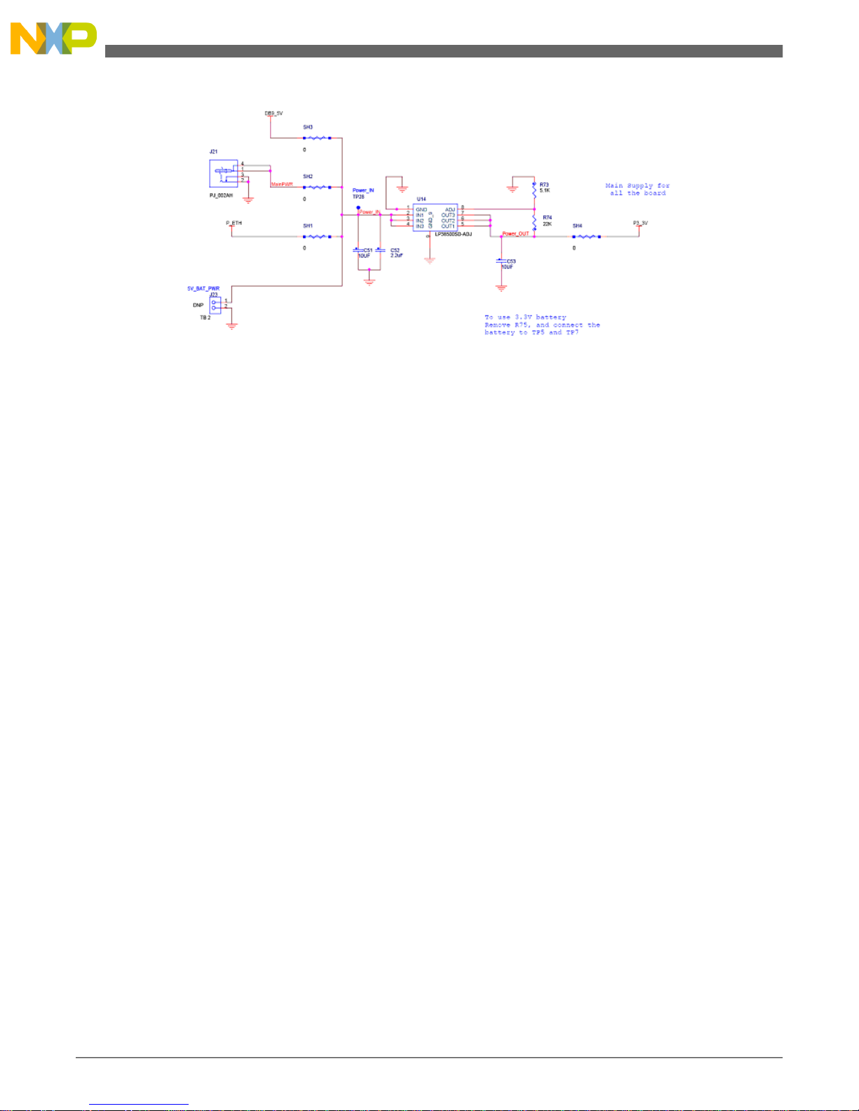
Figure 2-5. MCF51CN128 reference design board power options schematic
2.8 Hardware Considerations
The following list shows all the hardware considerations:
• Due to a reduced number of pins to all the functions required by the Demo System, an
analog switch is required to switch between pin functions.
• The following list shows shared functions that must be used exclusively:
• µSD card reader and I2C (temperature sensor)
• rs232 hardware signals and second SPI port (accelerometer sensor)
• Accelerometer sensor and µSD card connector while containing a µSD card.
• General purpose LED and second SPI port (accelerometer sensor)
• POT and second SPI port (accelerometer sensor)
• When using the Ethernet cable as the power supply, the length of the cable must be
considered due to the voltage drop.
TCP/IP Applications Using the MCF51CN Family—Designer Reference Manual, Rev. 0, 12/2009
Freescale Semiconductor20
Hardware Considerations
Page 21

Chapter 3
Firmware Description
3.1 Firmware
The software design characteristics are as follows:
• Use a layered approach to write code so it can be migrated faster to other MCUs like
the MCF5225x.
• Write code for the CodeWarrior 6.2.1 compiler.
• Use of existent software—FreeRTOS 5.3.0 as the RTOS and lwIP 1.3.0 as the TCP/IP
stack.
• Serial bridge must transmit data between the UART or the SPI to Ethernet.
• UART must support—Software, hardware flow control.
• Bridge parameters must be visible and configurable using a web browser.
• All serial parameters must be configurable without recompiling the code.
• Serial parameters must be configurable through the same serial interface.
• Static and dynamic IP addresses must be available.
• Web server must be able to show files from the µSD card.
• Web server must support persistent-connections.
• Firmware must be able to send an email.
• SD card files must be able to be updated through an FTP session (FTP server).
3.2 Firmware Organization
After reset, the firmware starts in one of the following modes:
• Serial Bridge Mode
TCP/IP Applications Using the MCF51CN Family—Designer Reference Manual, Rev. 0, 12/2009
21Freescale Semiconductor
Page 22

• The following services are functional:
• The selected serial (UART or SPI) to Ethernet bridge
• Static or dynamic IP address
• Email client with a dynamic IP address
• HTTP server without SD card support
• FAT16 support
• Configuration Mode
The following services are functional:•
• The selected serial (UART or SPI) to Ethernet configurator configures serial
parameters using predefined serial commands.
• Static or dynamic IP address
• Email client with dynamic IP address
• HTTP server with SD card support
• FTP Server with SD card support
NOTE
The SD does not work if the SPI configurator is
selected.
• FAT16 support
NOTE
The only difference between the serial bridge and configuration
mode is the serial function (bridge or configuration) and the FTP
server feature.
Configuration and reset can be requested at any time using a web page.
3.3 Block Diagram
The following figure shows how software is divided into functional pieces and joined
together to have a functional reference design software.
TCP/IP Applications Using the MCF51CN Family—Designer Reference Manual, Rev. 0, 12/2009
Freescale Semiconductor22
Block Diagram
Page 23
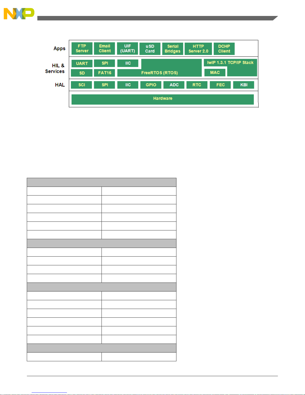
Figure 3-1. MCF51CN128 reference design software
3.4 System Startup
The following table sho ws all the default parameters after reset. The full table is implemented
in file constants.c.
Table 3-1. Default firmware parameters
Ethernet Options
00:CF:52:35:00:07MAC Address
192.168.1.3IP Address
255.255.255.0Subnet Mask IP Address
192.168.1.1Gateway IP Address
192.168.1.81Server IP Address
OFFDHCP
Serial Bridge Options
Configuration ModeMode
UART BridgeSerial Interface
ServerServer/Client
1234Port
UART Options
SCI2UART Port
19200Baudrate
No ParityParity
8 BitsNumber of Bits
1 Stop BitStop Bit
SoftwareFlow Control
SPI Options
SPI2SPI Port
TCP/IP Applications Using the MCF51CN Family—Designer Reference Manual, Rev. 0, 12/2009
23Freescale Semiconductor
Chapter 3 Firmware Description
Page 24
1MbpsBaudrate
Idle HighIdleness
Middle SampleSample
SPI MasterMaster/Slave
PollingInterrupt/Polling
Email Options
[email protected]Username
Freescale123Password
smtp113.plus.mail.mud.yahoo.comSTMP Server
YESAuthentication
3.5 Internal Functionality of Socket Layer
The following figure shows the socket flow from the server and client perspective.
TCP/IP Applications Using the MCF51CN Family—Designer Reference Manual, Rev. 0, 12/2009
Freescale Semiconductor24
Internal Functionality of Socket Layer
Page 25
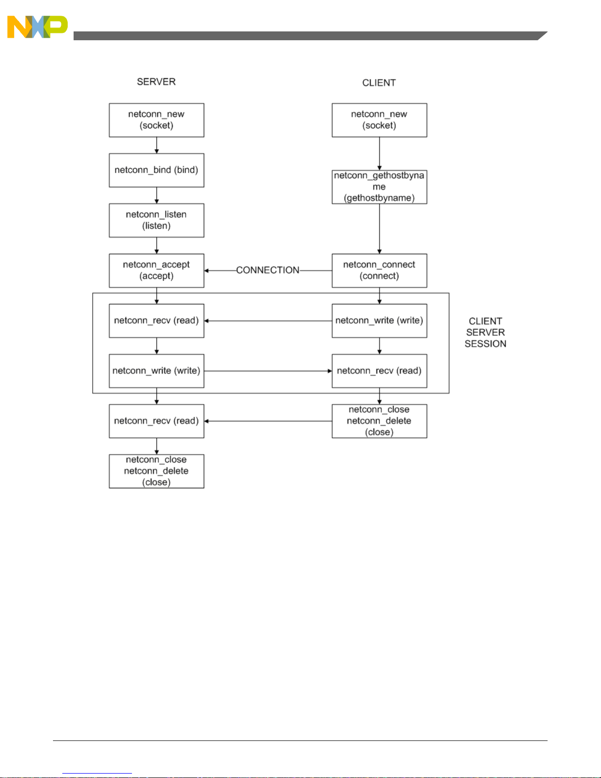
Figure 3-2. Socket flow diagram
TCP/IP Applications Using the MCF51CN Family—Designer Reference Manual, Rev. 0, 12/2009
25Freescale Semiconductor
Chapter 3 Firmware Description
Page 26

TCP/IP Applications Using the MCF51CN Family—Designer Reference Manual, Rev. 0, 12/2009
Freescale Semiconductor26
Internal Functionality of Socket Layer
Page 27
Chapter 4
System Setup
4.1 Getting Started
This section describes the using the software and hardware to demonstrate the use of this
reference design
4.2 Install Software
This is the process to download firmware to hardware:
• Connect the BDM Multilink or BDM Cyclone PRO to the MCF51CN128 reference
design hardware.
• Download software using CodeWarrior 6.2.1v compiler.
• Disconnect the BDM Multilink or BDM Cyclone PRO from the programmed target.
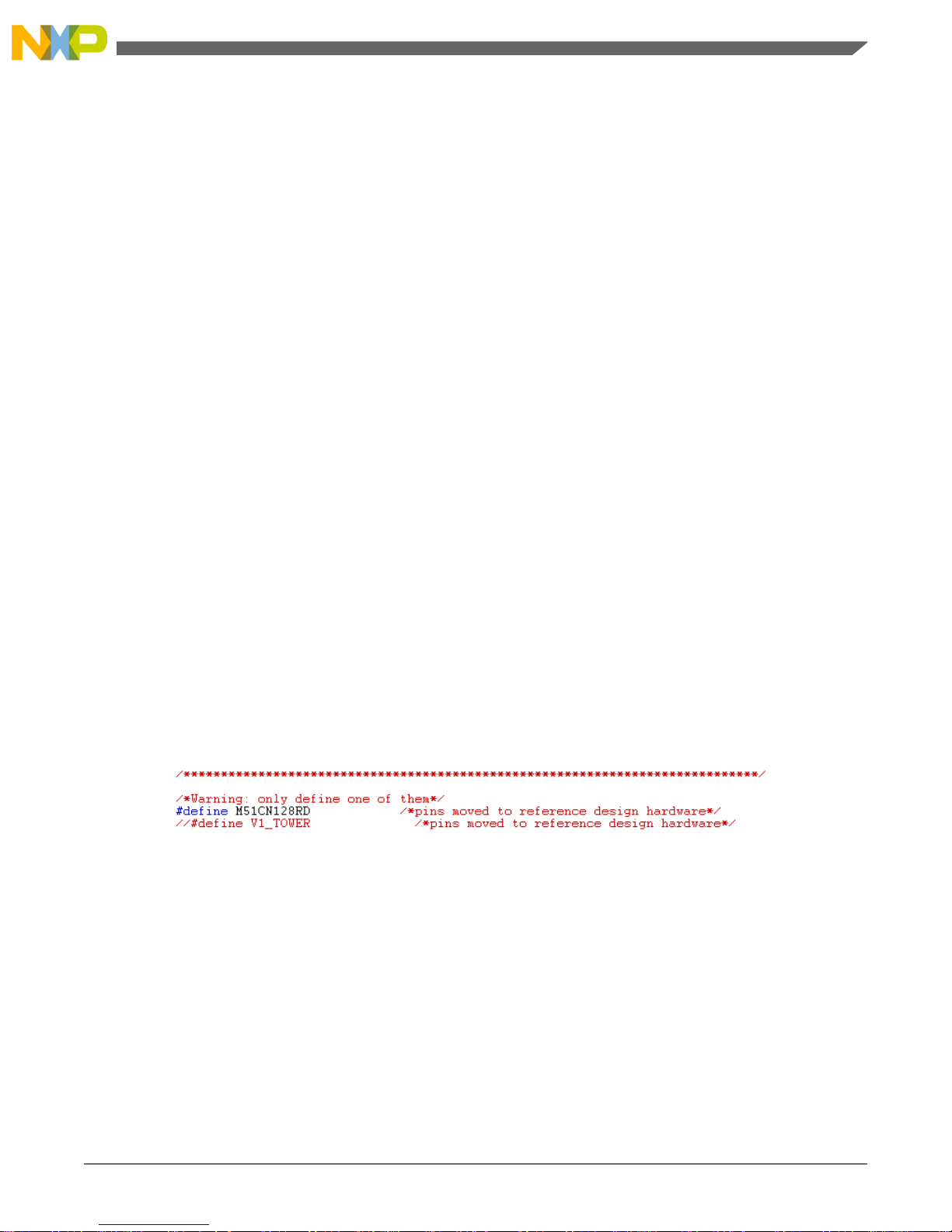
Before downloading the firmware to the MCF51CN128 reference design hardware, the
M51CN128RD C-macro must be selected. The file name is m51cn128evb.h.
Figure 4-1. Selection of the MCF51CN128 reference design hardware
4.3 Hardware Setup
For hardware setup, perform the following steps:
1. The power supply must be between 3.7 and 5.5 V because of regulator limits. To select
a different power source, go to .
2. The red LED near the RJ45 connector must be turned on as soon as the power is applied.
TCP/IP Applications Using the MCF51CN Family—Designer Reference Manual, Rev. 0, 12/2009
27Freescale Semiconductor
Page 28
4.3.1 HTTP Server Functionality
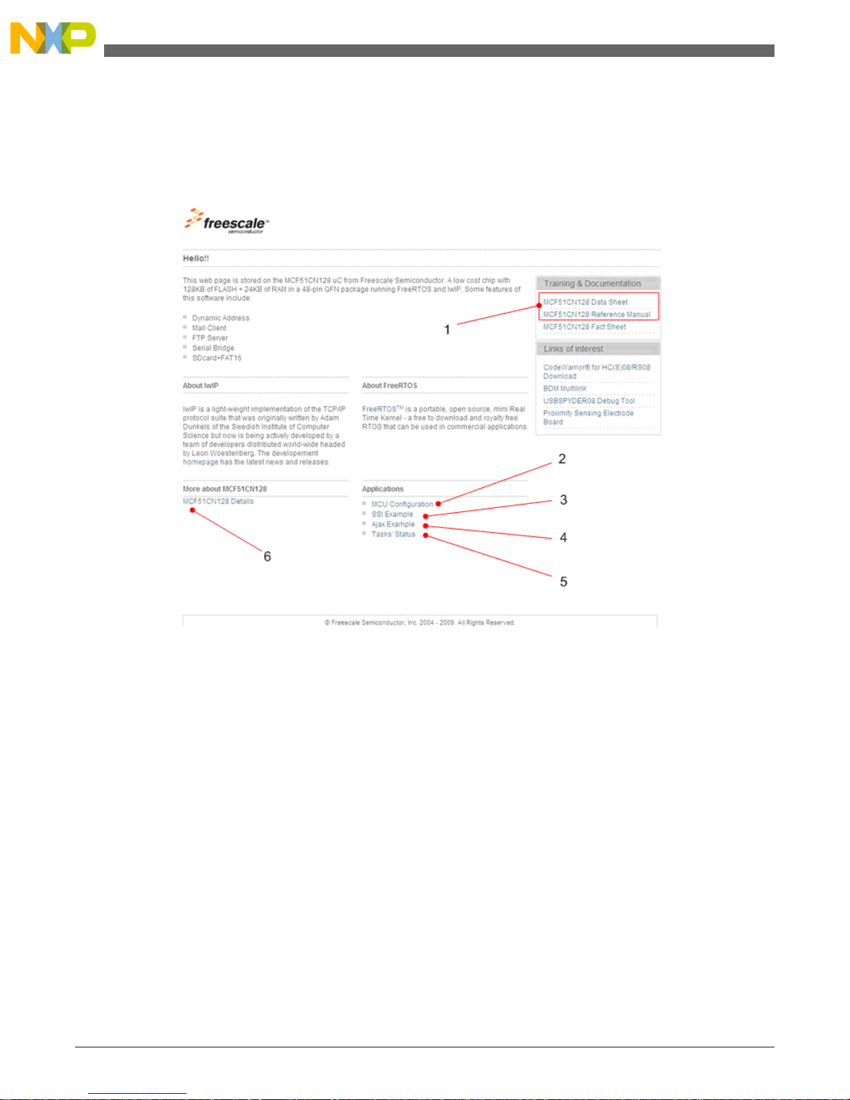
After running the sample program, the browser must show the following:
Figure 4-2. Default web page
1. Links to reference manual and data sheets. A connection to the Internet is required.
2. MCU Configuration page
3. SSI Example page
4. AJAX Example page
5. Tasks’ Status Example page
6. MCU features
From this default web page, the following pages are available:
If the MCU Configuration link is clicked, or config.shtml is requested from the browser,
the following web page shows the parameters that can be changed.
TCP/IP Applications Using the MCF51CN Family—Designer Reference Manual, Rev. 0, 12/2009
Freescale Semiconductor28
Hardware Setup
Page 29
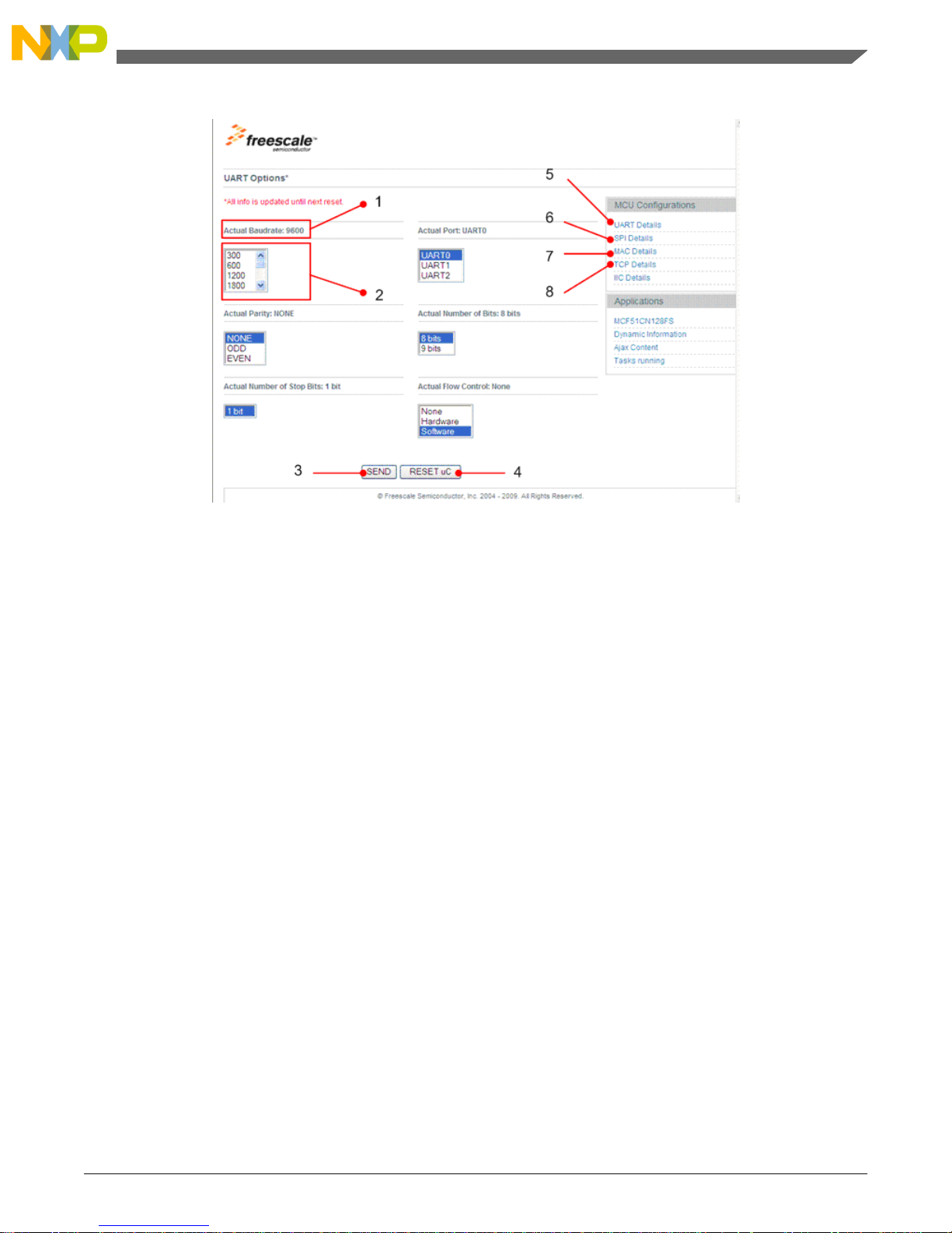
Figure 4-3. Configuration page
1. Actual settings
2. Options to select
3. Send new configuration to the MCU
4. Reset MCU
5. UART configuration
6. SPI configuration
7. MAC configuration
8. TCP configuration
Another application that is available in the web server is an AJAX example. The following
figure shows what is shown in the browser when ajax.htm is entered. The application
increments only the 8-bit counters and shows them graphically.
TCP/IP Applications Using the MCF51CN Family—Designer Reference Manual, Rev. 0, 12/2009
29Freescale Semiconductor
Chapter 4 System Setup
Page 30
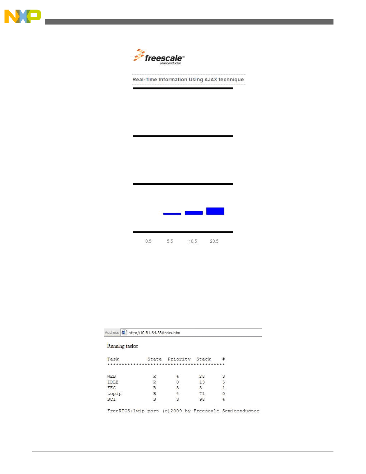
Figure 4-4. An AJAX web page dynamically updated at background
The RTOS tasks’ status are displayed showing valuable information like:
• Task name
• Task state
• Amount of stack available for the task, measured in longwords
Figure 4-5.Tasks’ status on the MCF51CN128
TCP/IP Applications Using the MCF51CN Family—Designer Reference Manual, Rev. 0, 12/2009
Freescale Semiconductor30
Hardware Setup
Page 31
4.3.2 Email Client Functionality
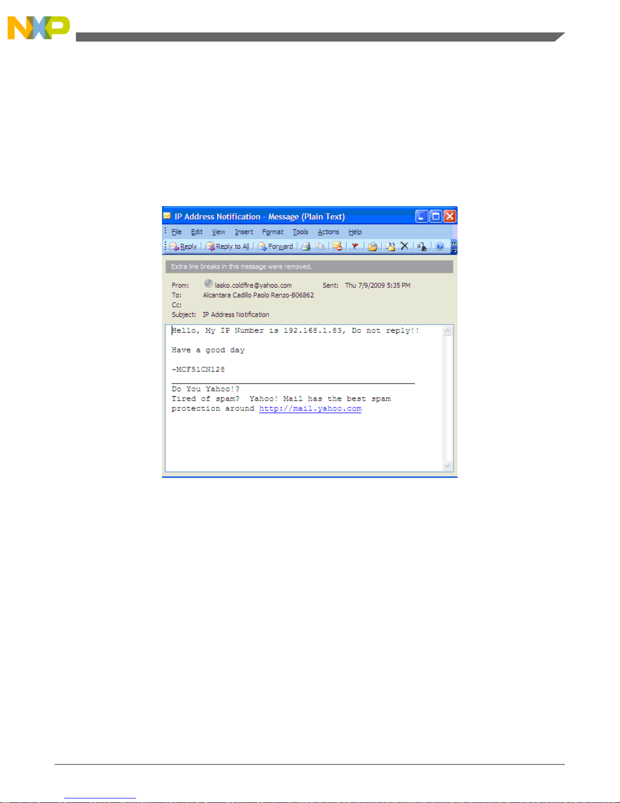
As soon as the firmware gets a valid IP address using DHCP, an email is sent. Email receipt,
subject, and content are defined at file dhcp_app.c. Email origin, password, authentication
flag, and SMTP server are defined at file constants.c.
The following figure shows a received email sent by the system.
Figure 4-6. Email sent by the MCF51CN128 reference design
The following email client implementation does not deal with encryption. Almost all the
actual SMTP servers use secure socket layer (SSL) to correctly sign-in and exchange
information over a secure communication protocol. Popular email service providers like
Hotmail, Yahoo, or Google accept SSL. File attachments to emails need to be considered
in the future.
At the time of testing this software, the following SMTP serv er is the only one that accepts
regular requests without SSL:
smtp113.plus.mail.mud.yahoo.com
The username and password used with the Yahoo email account are stored at constants.c
and might not be valid during testing.
TCP/IP Applications Using the MCF51CN Family—Designer Reference Manual, Rev. 0, 12/2009
31Freescale Semiconductor
Chapter 4 System Setup
Page 32
4.3.3 FTP Server Functionality
The MCF51CN128 reference design is able to start an FTP server if the following conditions
are met:
• Configuration mode is running, not using SPI interface
• A valid µSD card is connected with a valid FAT16 file system
The following table shows the list of interpreted commands implemented when using
Microsoft Windows command-line FTP client. They are interpreted because one or more
FTP commands are required to run the interpreted command. For example, LS will require
PORT and NLST to work.
Table 4-1. Microsoft Windows command-line FTP client implemented commands
DescriptionFTP client
Displays filesLS
Copy a file from FTP server to FTP clientGET [filename]
Copy a file from FTP client to FTP serverPUT [filename]
Delete a file from FTP serverDELETE [filename]
Ends FTP sessionQUIT
Shows description of FTP commandsHELP
The following figure sho ws an established FTP client session to the FTP server application.
A username and password are required to view the files. Later on, the files can be:
• Listed
• Uploaded
• Downloaded
• Deleted
TCP/IP Applications Using the MCF51CN Family—Designer Reference Manual, Rev. 0, 12/2009
Freescale Semiconductor32
Hardware Setup
Page 33
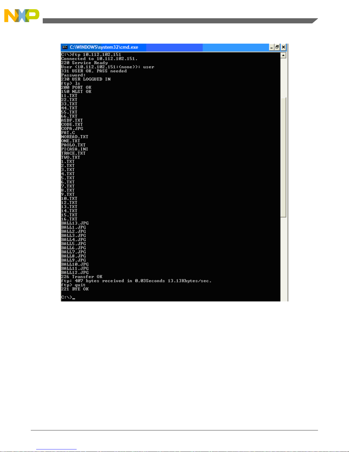
Figure 4-7. Microsoft Windows command-line FTP client with the MCF51CN128
For this implementation the following information is required to log in:
Username: user
Password: Freescale123
FTP server implementation has the following limitations:
• Only allows one client and one transfer at a time.
• FTP server was tested using only Microsoft Windows command-line FTP client.
TCP/IP Applications Using the MCF51CN Family—Designer Reference Manual, Rev. 0, 12/2009
33Freescale Semiconductor
Chapter 4 System Setup
Page 34

• If an unimplemented command is received, the FTP client is notified and the FTP
session is closed.
For the FAT16 implementation, there are two limitations:
• The name of the file must be up to eight characters and the extension must be up to
three characters.
• Current implementation does not work with directories.
4.3.4 Serial Bridge Functionality
The Serial Bridge can work in two modes:
• Configuration mode—Serial interface (UART or SPI) is used to configure the serial
bridge. This is the default mode.
• Bridge mode—Characters received at serial interface, are sent to Ethernet and vice
verse.
The Ethernet side can be tested using HyperTerminal with the following information:
TCP/IP Applications Using the MCF51CN Family—Designer Reference Manual, Rev. 0, 12/2009
Freescale Semiconductor34
Hardware Setup
Page 35
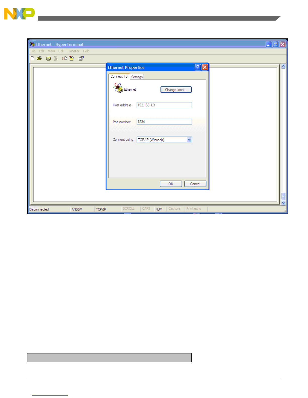
Figure 4-8. Microsoft HyperTerminal settings to test serial bridge
The UAR T can be tested using a standard serial terminal lik e HyperT erminal. In this example,
the HyperTerminal using TCP/IP (Winsock) works as a TCP client and the firmware as a
TCP server. The client must then specify the server’s address to get a connection.
For details about default UART or SPI settings, go to Section 4.4 To configure the serial
interface, go to Section 4.5
4.4 Principle of Operation
The Serial Bridge works in Configuration and Bridge modes. The Web server interface
works at all time, but the serial configuration (U AR T or SPI) only works in the configuration
mode.
The Serial Bridge starts with the following configuration:
Table 4-2. Reference design default parameters
MAC Parameters
TCP/IP Applications Using the MCF51CN Family—Designer Reference Manual, Rev. 0, 12/2009
35Freescale Semiconductor
Chapter 4 System Setup
Page 36
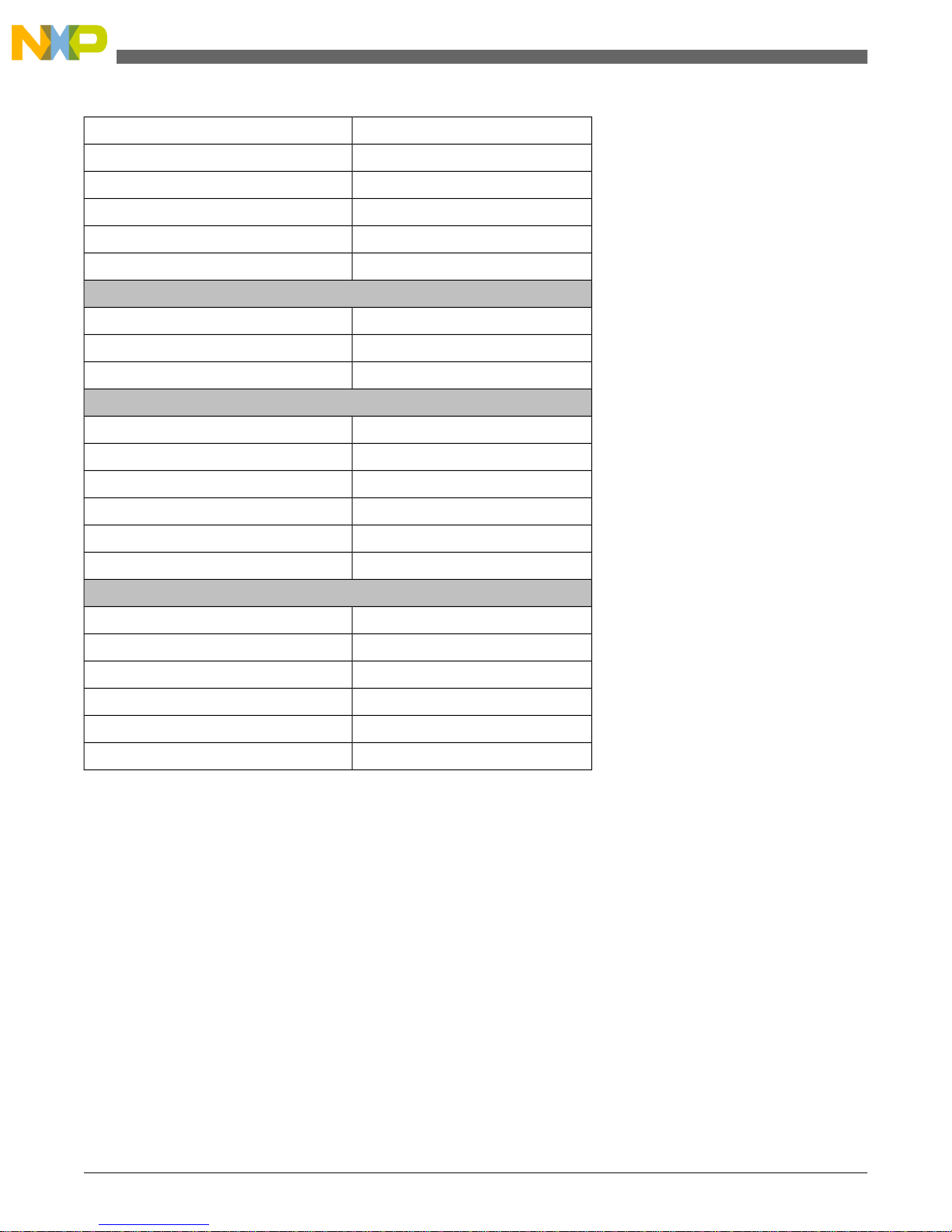
00:CF:52:35:00:01MAC Address
192.168.1.3 for static implementationIP Address
255.255.255.0Mask Address
192.168.1.1Gateway Address
192.168.1.3Server Address to Connect to an Address
StaticStatic or Dynamic Address
TCP Parameters
1234TCP Port to Connect to
192.168.1.3Client or server implementation
ConfigurationConfiguration or bridge Implementation
UART Parameters
First PortPort
19200Baudrate
NONEParity
8Number of bits
1Number of Stop bits
SW Flow ControlFlow Control
SPI Parameters
Second PortPort
1 MbpsBaudrate
LowPolarity
MiddlePhase
MasterMaster or Slave
PollingPolling or Interrupt Handling
4.5 Serial Configuration Commands
In configuration mode, the serial configuration task is enabled. The purpose of this task is
to configure all the serial parameters stated in Section1.2 Key Features . Default settings
are stated in Table 4-2. The configuration is made through a set of commands that are sent
using the UAR T or SPI interf ace. These commands are sent from the data terminal equipment
(DTE), like a PC to the MCF51CN128 reference design hardware.
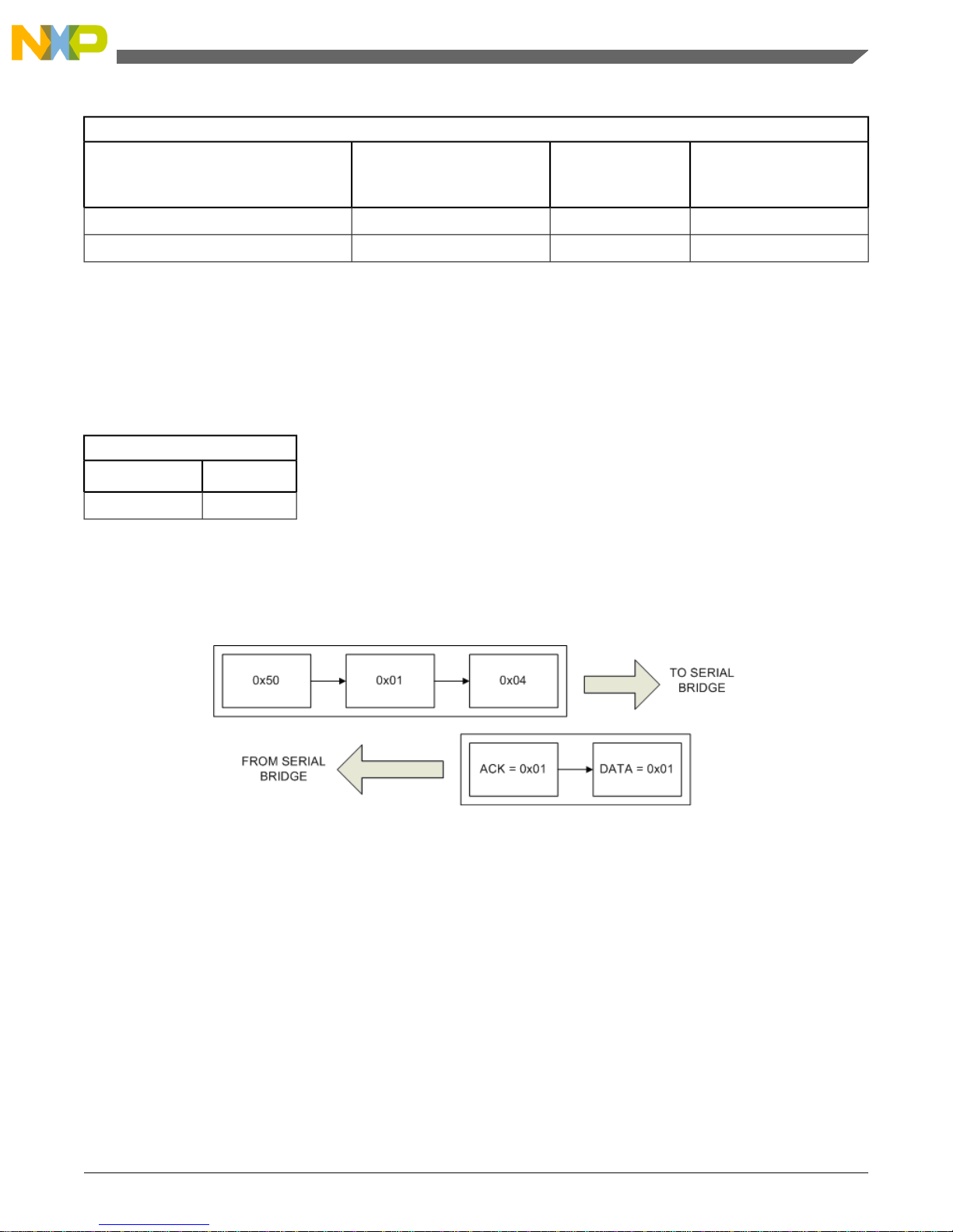
Table 4-3, Table 4-4, and Table 4-5 list all available commands. For example, if the
board_get_uart_port command is requested, the serial interface must send the packet as
shown in Figure 4-9.
TCP/IP Applications Using the MCF51CN Family—Designer Reference Manual, Rev. 0, 12/2009
Freescale Semiconductor36
Serial Configuration Commands
Page 37
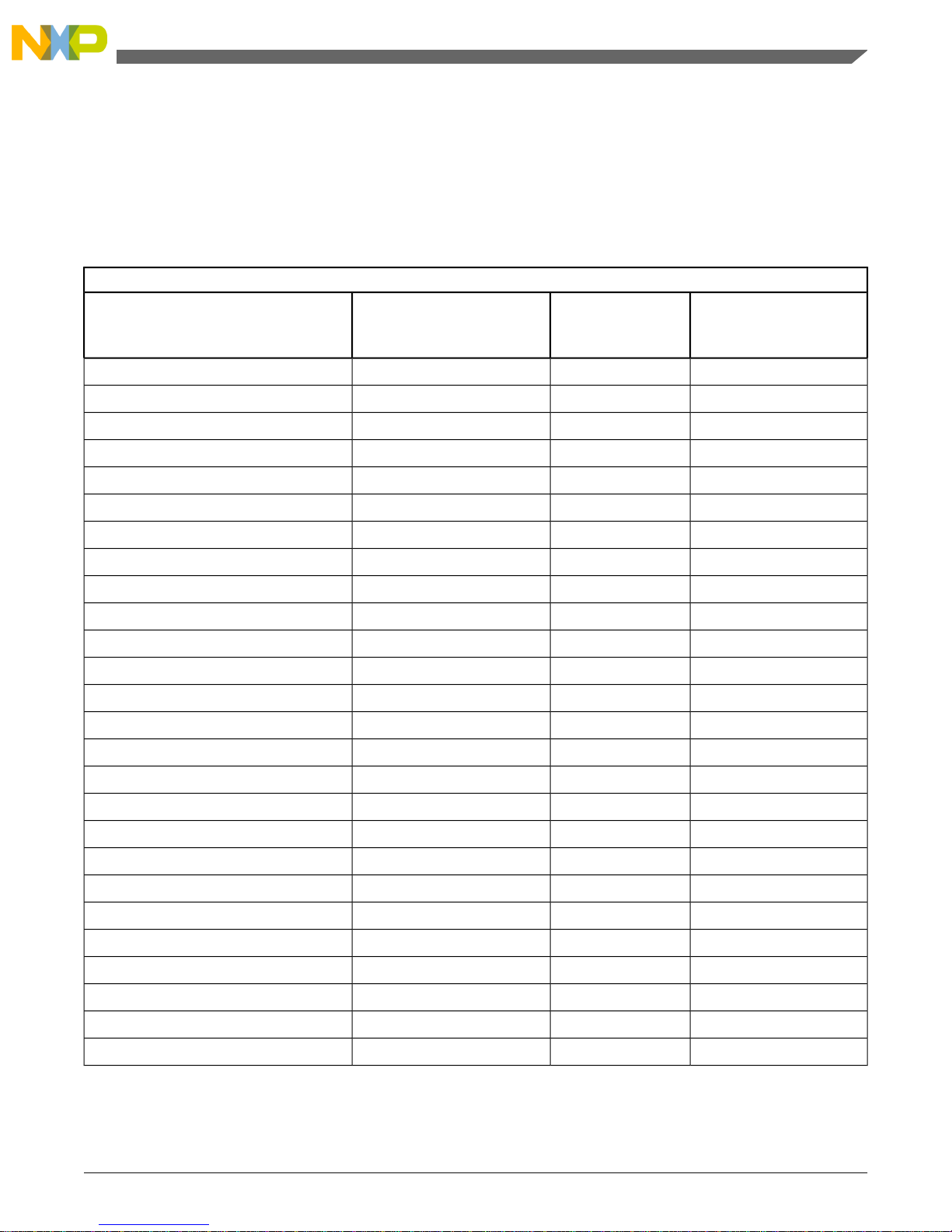
For the GET commands, three characters are needed to identify the command. If it is not a
valid command, then a single zero byte is returned as an answer. For a v alid command, the
number of returned characters is equal to:
1 byte for ACK + Number of bytes stated at 2nd byte of requested command.
Table 4-3. Get commands to get bridge parameters
GET Commands
3rd Character—
SubCommand ID
2
nd
Character—Number
of Parameters
1st Character—Command ID
Command Name
010x50board_get_eth_dhcp_auto
110x50board_get_bridge_configuration
210x50board_get_bridge_tcp_mode
310x50board_get_bridge_tcp_server
410x50board_get_uart_port
510x50board_get_uart_parity
610x50board_get_uart_number_of_bits
710x50board_get_uart_stop_bits
810x50board_get_uart_flow_control
910x50board_get_spi_port
1010x50board_get_spi_polarity
1110x50board_get_spi_phase
1210x50board_get_spi_master
1310x50board_get_spi_interrupt
1410x50board_get_email_authentication_required
020x50board_get_bridge_tcp_port
120x50board_get_spi_baud
040x50board_get_eth_ip_add
140x50board_get_eth_netmask
240x50board_get_eth_gateway
340x50board_get_eth_server_add
440x50board_get_uart_baud
060x50board_get_eth_ethaddr
160x50board_get_email_username
260x50board_get_email_password
360x50board_get_email_smtp_server
TCP/IP Applications Using the MCF51CN Family—Designer Reference Manual, Rev. 0, 12/2009
37Freescale Semiconductor
Chapter 4 System Setup
Page 38
Note
Get functions return the same number of characters of the
“Number of Parameters.”
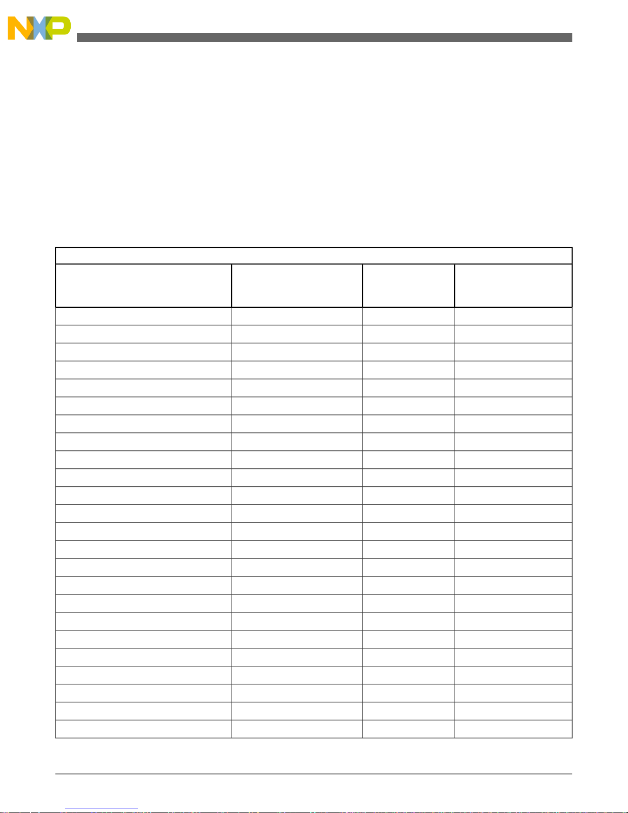
For the SET commands, the following number of bytes is required for each command:
3 bytes for all SET commands + Number of bytes stated at 2nd byte of requested command
For a valid command, one is returned, otherwise zero is returned.
Table 4-4. Set commands to change bridge parameters
SET Commands
3rd Character—
SubCommand ID
2
nd
Character—Number
of Parameters
1st Character— Command ID
Command Name
010xA0board_set_eth_dhcp_auto
110xA0board_set_bridge_configuration
210xA0board_set_bridge_tcp_mode
310xA0board_set_bridge_tcp_server
410xA0board_set_uart_port
510xA0board_set_uart_parity
610xA0board_set_uart_number_of_bits
710xA0board_set_uart_stop_bits
810xA0board_set_uart_flow_control
910xA0board_set_spi_port
1010xA0board_set_spi_polarity
1110xA0board_set_spi_phase
1210xA0board_set_spi_master
1310xA0board_set_spi_interrupt
1410xA0board_set_email_authentication_required
020xA0board_set_bridge_tcp_port
120xA0board_set_spi_baud
040xA0board_set_eth_ip_add
140xA0board_set_eth_netmask
240xA0board_set_eth_gateway
340xA0board_set_eth_server_add
440xA0board_set_uart_baud
060xA0board_set_eth_ethaddr
160xA0board_set_email_username
TCP/IP Applications Using the MCF51CN Family—Designer Reference Manual, Rev. 0, 12/2009
Freescale Semiconductor38
Serial Configuration Commands
Page 39
SET Commands
3rd Character—
SubCommand ID
2
nd
Character—Number
of Parameters
1st Character— Command ID
Command Name
260xA0board_set_email_password
360xA0board_set_email_smtp_server
Note
Set functions will return zero if the command was correctly
executed. If any other number is returned, the command has f ailed.
Reset command is a single character command, as shown in the following table.
Table 4-5. Get commands to change bridge parameters
RST Command
1st Character
Command Name
0x88Reset the Board
Note
Reset function returns zero if it was correctly received.
For example, to ask for the serial’ s port configuration, the follo wing sequence must be sent:
Figure 4-9. Packet visual explanation
The answer from the bridge means it correctly received the command, and the UART port
configuration is located at port number 1.
All settings are reloaded as soon as the reset command is requested.
4.6 Support
For any questions regarding this reference design, submit a service request using
www.freescale.com/support.
TCP/IP Applications Using the MCF51CN Family—Designer Reference Manual, Rev. 0, 12/2009
39Freescale Semiconductor
Chapter 4 System Setup
Page 40

TCP/IP Applications Using the MCF51CN Family—Designer Reference Manual, Rev. 0, 12/2009
Freescale Semiconductor40
Support
Page 41

Appendix A
A.1 Additional Files
The following files are included with this reference design in a zip file called DRM114.zip.
• CodeWarrior project containing the firmware—[DRM114SW.zip]
• Bill of materials (BOM)—[BOM-25981_A.xls]
• PDF schematic files—[SPF-25981_A.pdf]
• Hardware source files—[SCH-25981_A.zip]
• Hardware layout file—[LAY-25981_A.zip]
• Gerber files—[GRB-25981_A.zip]
These files are provided free of charge to Freescale users.
TCP/IP Applications Using the MCF51CN Family—Designer Reference Manual, Rev. 0, 12/2009
41Freescale Semiconductor
Page 42

TCP/IP Applications Using the MCF51CN Family—Designer Reference Manual, Rev. 0, 12/2009
Freescale Semiconductor42
Page 43
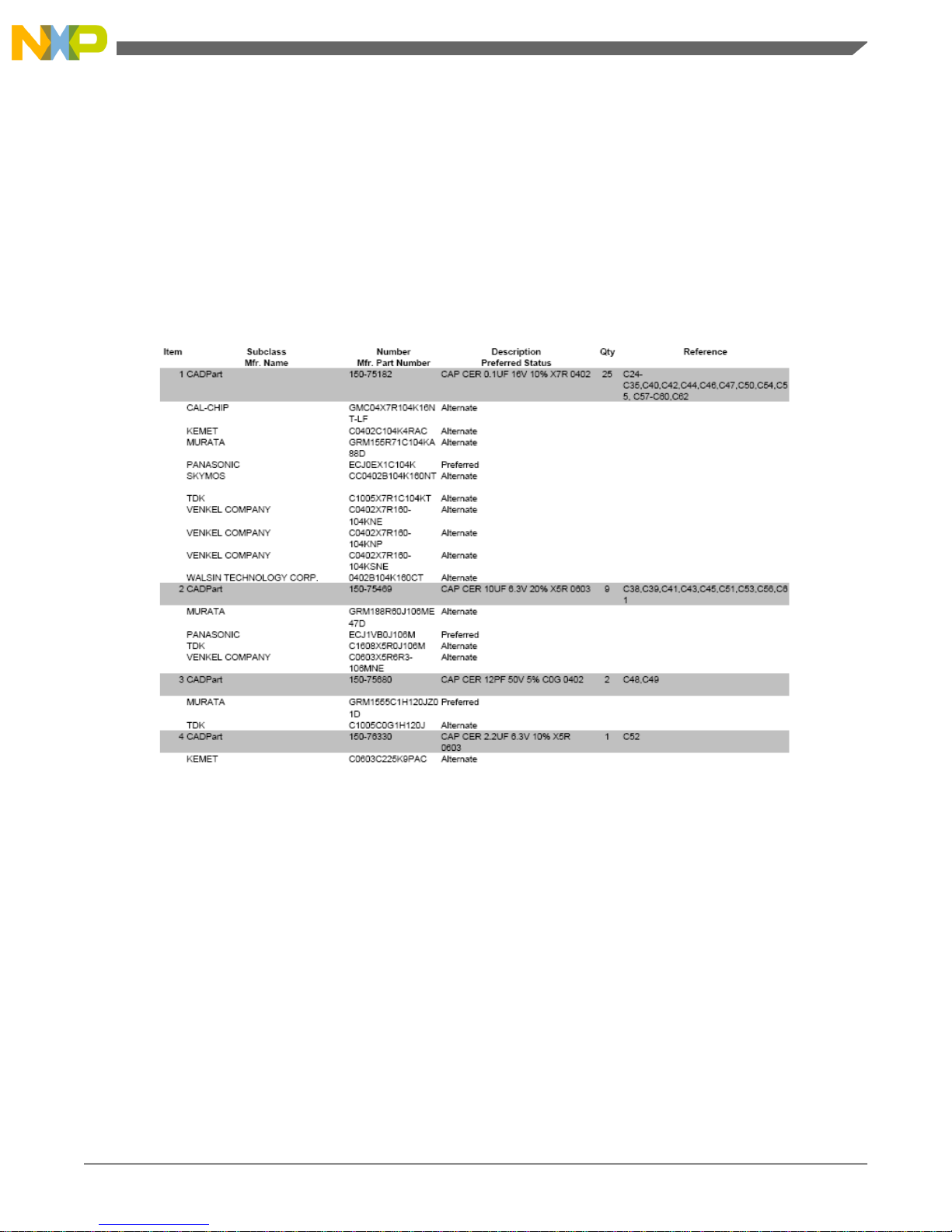
Appendix B
B.1 Bill of Materials (BOM)
TCP/IP Applications Using the MCF51CN Family—Designer Reference Manual, Rev. 0, 12/2009
43Freescale Semiconductor
Page 44
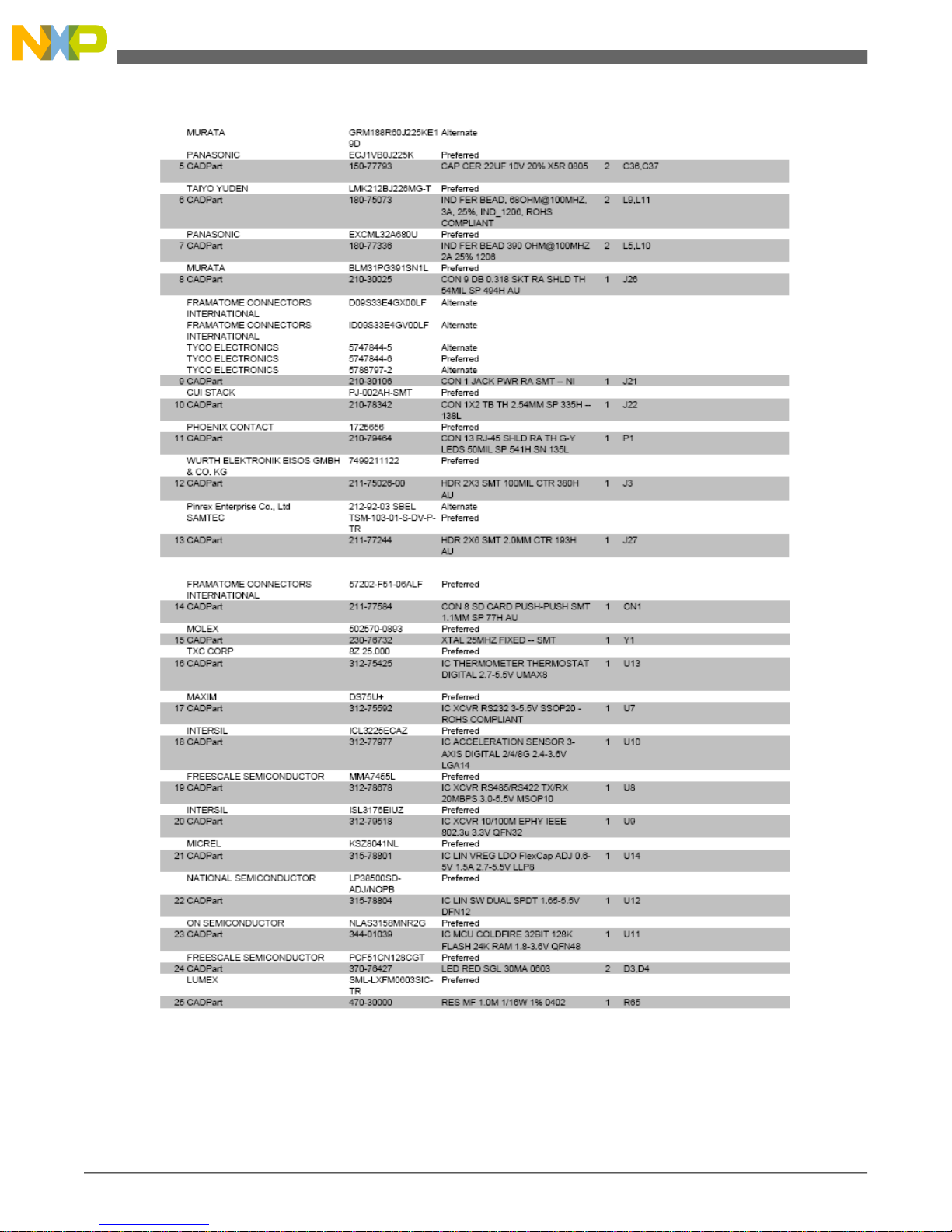
TCP/IP Applications Using the MCF51CN Family—Designer Reference Manual, Rev. 0, 12/2009
Freescale Semiconductor44
Bill of Materials (BOM)
Page 45
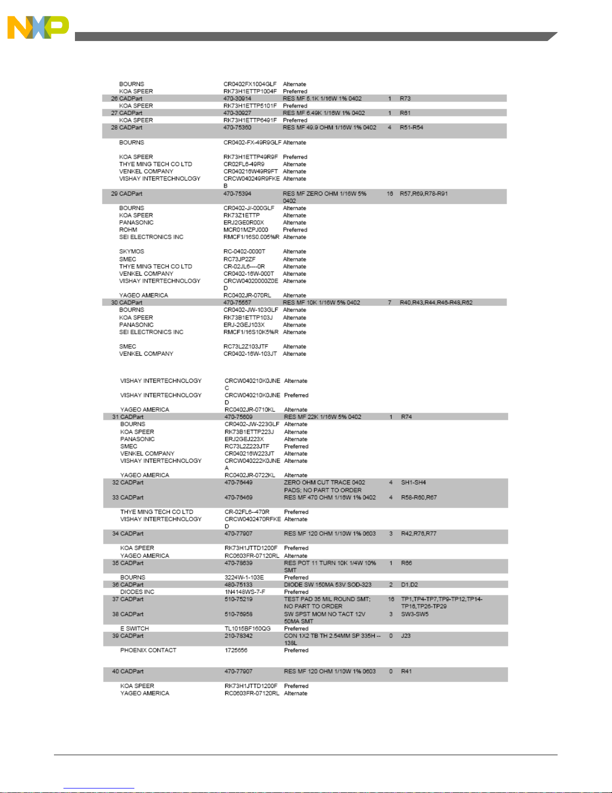
Figure B-1. Manufacturer BOM Report
TCP/IP Applications Using the MCF51CN Family—Designer Reference Manual, Rev. 0, 12/2009
45Freescale Semiconductor
Page 46

TCP/IP Applications Using the MCF51CN Family—Designer Reference Manual, Rev. 0, 12/2009
Freescale Semiconductor46
Page 47
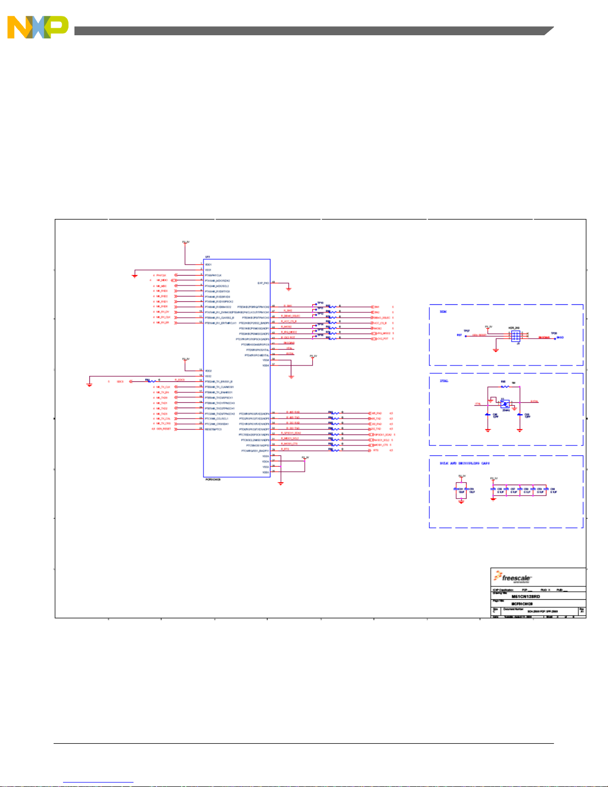
Appendix C
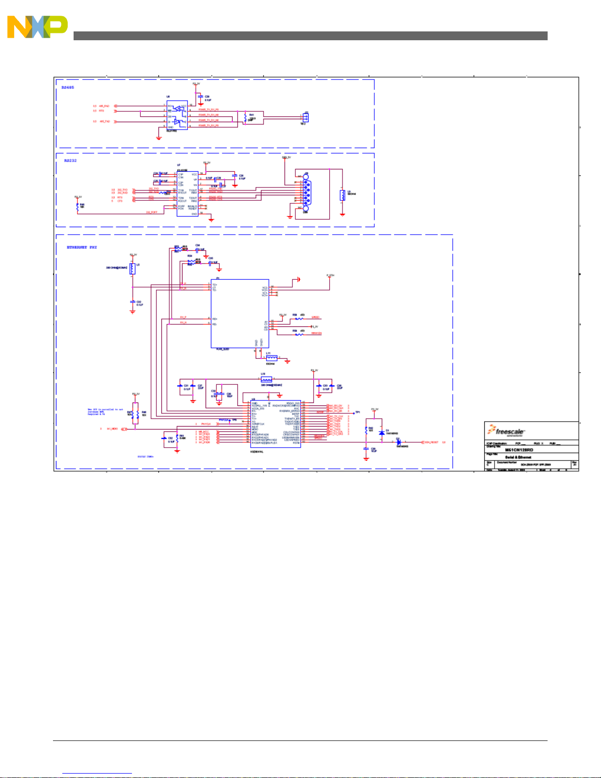
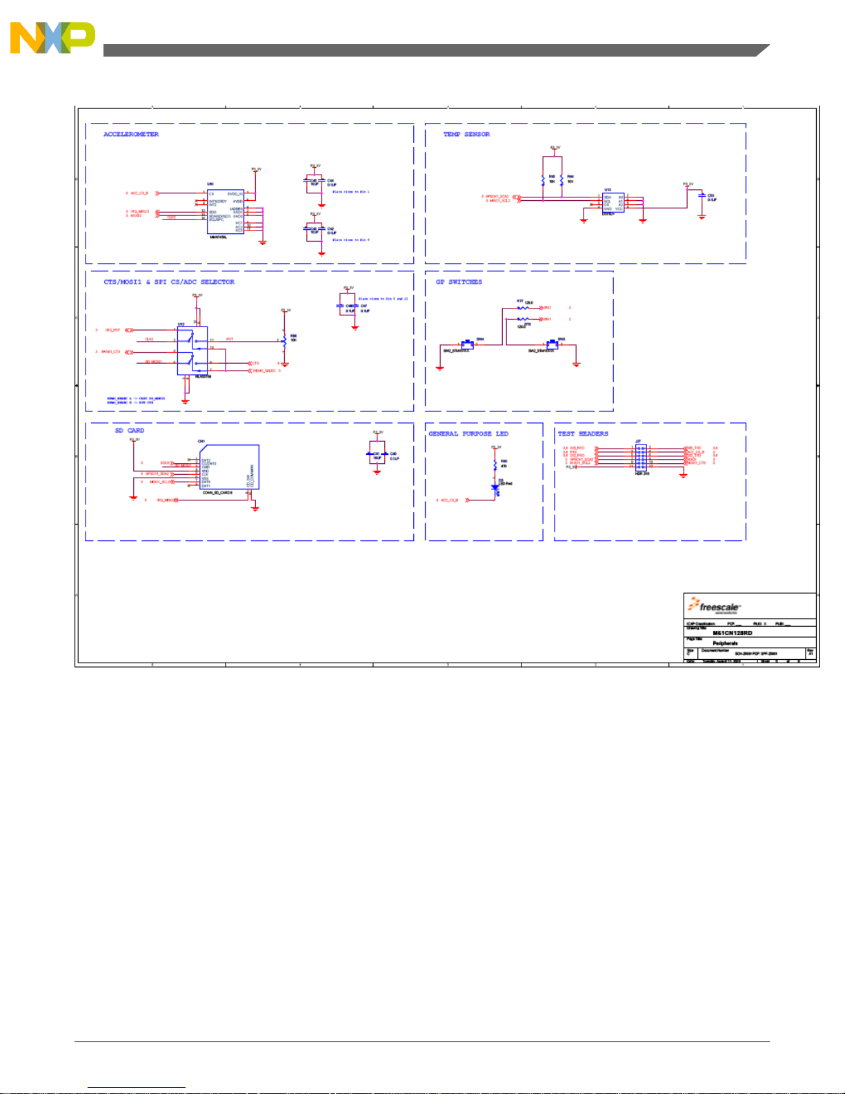
C.1 Schematics
TCP/IP Applications Using the MCF51CN Family—Designer Reference Manual, Rev. 0, 12/2009
47Freescale Semiconductor
Page 48
TCP/IP Applications Using the MCF51CN Family—Designer Reference Manual, Rev. 0, 12/2009
Freescale Semiconductor48
Schematics
Page 49
TCP/IP Applications Using the MCF51CN Family—Designer Reference Manual, Rev. 0, 12/2009
49Freescale Semiconductor
Appendix C
Page 50
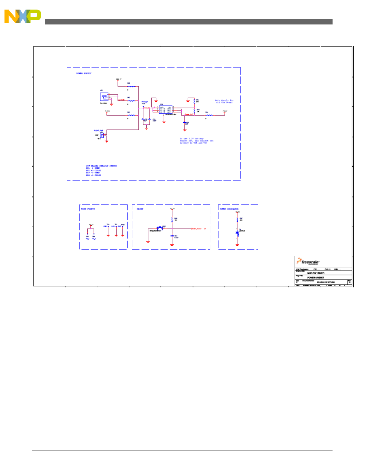
Figure C-1. MCF51CN128 reference design schematics
TCP/IP Applications Using the MCF51CN Family—Designer Reference Manual, Rev. 0, 12/2009
Freescale Semiconductor50
Page 51

How to Reach Us:
Home Page:
www.freescale.com
Web Support:
http://www.freescale.com/support
USA/Europe or Locations Not Listed:
Freescale Semiconductor
Technical Information Center, EL516
2100 East Elliot Road
Tempe, Arizona 85284
+1-800-521-6274 or +1-480-768-2130
www.freescale.com/support
Europe, Middle East, and Africa:
Freescale Halbleiter Deutschland GmbH
Technical Information Center
Schatzbogen 7
81829 Muenchen, Germany
+44 1296 380 456 (English)
+46 8 52200080 (English)
+49 89 92103 559 (German)
+33 1 69 35 48 48 (French)
www.freescale.com/support
Japan:
Freescale Semiconductor Japan Ltd.
Headquarters
ARCO Tower 15F
1-8-1, Shimo-Meguro, Meguro-ku,
Tokyo 153-0064
Japan
0120 191014 or +81 3 5437 9125
[email protected]
Asia/Pacific:
Freescale Semiconductor China Ltd.
Exchange Building 23F
No. 118 Jianguo Road
Chaoyang District
Beijing 100022
China
+86 10 5879 8000
[email protected]
For Literature Requests Only:
Freescale Semiconductor Literature Distribution Center
1-800-441-2447 or +1-303-675-2140
Fax: +1-303-675-2150
[email protected]
Document Number: DRM114
Rev. 0, 12/2009
Information in this document is provided solely to enable system and sofware implementers
to use Freescale Semiconductors products. There are no express or implied copyright licenses
granted hereunder to design or fabricate any integrated circuits or integrated circuits based
on the information in this document.
Freescale Semiconductor reserves the right to make changes without further notice to any
products herein. Freescale Semiconductor makes no warranty, representation, or guarantee
regarding the suitability of its products for any particular purpose, nor does Freescale
Semiconductor assume any liability arising out of the application or use of any product or
circuit, and specifically disclaims any liability, including without limitation consequential
or incidental damages. "Typical" parameters that may be provided in Freescale
Semiconductor data sheets and/or specifications can and do vary in different applications
and actual performance may vary over time. All operating parameters, including "T ypicals",
must be validated for each customer application by customer's technical experts. Freescale
Semiconductor does not convey any license under its patent rights nor the rights of others.
Freescale Semiconductor prodcuts are not designed, intended, or authorized for use as
components in systems intended for surgical implant into the body, or other applications
intended to support or sustain life, or for any other application in which failure of the
Freescale Semiconductor product could create a situation where personal injury or death
may occur. Should Buyer purchase or use Freescale Semiconductor products for any such
unintended or unauthorized application, Buyer shall indemnify Freescale Semiconductor
and its officers, employees, subsidiaries, affiliates, and distributors harmless against all
claims, costs, damages, and expenses, and reasonable attorney fees arising out of, directly
or indirectly, any claim of personal injury or death associated with such unintended or
unauthorized use, even if such claims alleges that Freescale Semiconductor was negligent
regarding the design or manufacture of the part.
RoHS-compliant and/or Pb-free versions of Freescale products have the functionality and
electrical characteristics as their non-RoHS-complaint and/or non-Pb-free counterparts. For
further information, see http://www.freescale.com or contact your Freescale sales
representative.
For information on Freescale's Environmental Products program, go to
http://www.freescale.com/epp.
Freescale™ and the Freescale logo are trademarks of Freescale Semiconductor, Inc. All
other product or service names are the property of their respective owners.
© Freescale Semiconductor, Inc.2009. All rights reserved.
 Loading...