

Page 1

Freescale Semiconductor, Inc.
Using the ASB520
MC68HC908QT2
Based Infrared
nc...
I
cale Semiconductor,
Frees
M68HC08
Microcontrollers
Remote Control
Reference PC Board
Designer Reference
Manual
DRM045/D
Rev. 0
9/2003
MOTOROLA.COM/SEMICONDUCTORS
For More Information On This Product,
Go to: www.freescale.com
Page 2

Freescale Semiconductor, Inc.
nc...
I
cale Semiconductor,
Frees
For More Information On This Product,
Go to: www.freescale.com
Page 3

Freescale Semiconductor, Inc.
Using the ASB520 MC68HC908QT2 Based
Infrared Remote Control Reference
PC Board
nc...
I
cale Semiconductor,
Frees
Reference Design
By: Bill Lucas
Motorola Transportation and Standard Products Group
Austin, TX
To provide the most up-to-date information, the revision of our documents on
the World Wide Web will be the most current. Your printed copy may be an
earlier revision. To verify you have the latest information available, refer to:
http://motorola.com/semiconductors
The following revision history table summarizes changes contained in this
document. For your convenience, the page number designators have been
linked to the appropriate location.
Motorola and the Stylized M Logo are registered trademarks of Motorola, Inc.
DigitalDNA is a trademark of Motorola, Inc.
This product incorporates SuperFlash® technology licensed from SST. © Motorola, Inc., 2003
Using the ASB520 MC68HC908QT2 Based Infrared Remote Control Reference PC Board DRM045
MOTOROLA 3
For More Information On This Product,
Go to: www.freescale.com
Page 4

Revision History
Freescale Semiconductor, Inc.
Revision History
Date
September,
2003
nc...
I
Revision
Level
N/A Initial release N/A
Description
cale Semiconductor,
Page
Number(s)
Frees
DRM045 Using the ASB520 MC68HC908QT2 Based Infrared Remote Control Re ference PC Board
4 Revision History MOTOROLA
For More Information On This Product,
Go to: www.freescale.com
Page 5

Freescale Semiconductor, Inc.
Designer Reference Manual — DRM045
Section 1. Introduction and Setup
1.1 Introduction. . . . . . . . . . . . . . . . . . . . . . . . . . . . . . . . . . . . . . . . . . . . . 7
1.2 About this Manual. . . . . . . . . . . . . . . . . . . . . . . . . . . . . . . . . . . . . . . . 7
1.3 Setup Guide . . . . . . . . . . . . . . . . . . . . . . . . . . . . . . . . . . . . . . . . . . . . 8
Table of Contents
nc...
I
cale Semiconductor,
Frees
Section 2. Operational Description
2.1 Introduction. . . . . . . . . . . . . . . . . . . . . . . . . . . . . . . . . . . . . . . . . . . . 11
2.2 Push Buttons . . . . . . . . . . . . . . . . . . . . . . . . . . . . . . . . . . . . . . . . . . 11
2.3 LEDs. . . . . . . . . . . . . . . . . . . . . . . . . . . . . . . . . . . . . . . . . . . . . . . . . 11
2.3.1 Red Activity Indicator LED . . . . . . . . . . . . . . . . . . . . . . . . . . . . . 11
2.3.2 Infrared LED . . . . . . . . . . . . . . . . . . . . . . . . . . . . . . . . . . . . . . . . 11
2.4 Header and Jumpers Blocks. . . . . . . . . . . . . . . . . . . . . . . . . . . . . . . 13
2.5 Microcontroller Current Monitor Jumper Block . . . . . . . . . . . . . . . . . 14
Section 3. Pin Description
3.1 Introduction. . . . . . . . . . . . . . . . . . . . . . . . . . . . . . . . . . . . . . . . . . . . 15
3.2 16-Pin Connector J1. . . . . . . . . . . . . . . . . . . . . . . . . . . . . . . . . . . . . 15
Section 4. Schematic and Parts List
4.1 Introduction. . . . . . . . . . . . . . . . . . . . . . . . . . . . . . . . . . . . . . . . . . . . 17
4.2 Schematic. . . . . . . . . . . . . . . . . . . . . . . . . . . . . . . . . . . . . . . . . . . . . 17
4.3 Parts List. . . . . . . . . . . . . . . . . . . . . . . . . . . . . . . . . . . . . . . . . . . . . . 19
Section 5. Design Considerations
5.1 Introduction. . . . . . . . . . . . . . . . . . . . . . . . . . . . . . . . . . . . . . . . . . . . 21
5.2 Grounding. . . . . . . . . . . . . . . . . . . . . . . . . . . . . . . . . . . . . . . . . . . . . 21
5.3 Infrared and Visible LED Drive Circuit . . . . . . . . . . . . . . . . . . . . . . . 21
5.4 Switch Circuitry. . . . . . . . . . . . . . . . . . . . . . . . . . . . . . . . . . . . . . . . . 22
Section 6. System Testing
6.1 Introduction. . . . . . . . . . . . . . . . . . . . . . . . . . . . . . . . . . . . . . . . . . . . 25
6.2 Hardware/Software Testing Summary . . . . . . . . . . . . . . . . . . . . . . . 25
6.3 FLASH Programming . . . . . . . . . . . . . . . . . . . . . . . . . . . . . . . . . . . . 25
6.4 LED and Push Button Test Code . . . . . . . . . . . . . . . . . . . . . . . . . . . 26
6.5 DVD Player Control Test . . . . . . . . . . . . . . . . . . . . . . . . . . . . . . . . . 27
Using the ASB520 MC68HC908QT2 Based Infrared Remote Control Reference PC Board DRM045
MOTOROLA Table of Contents 5
For More Information On This Product,
Go to: www.freescale.com
Page 6

Table of Contents
nc...
I
Freescale Semiconductor, Inc.
cale Semiconductor,
Frees
DRM045 Using the ASB520 MC68HC908QT2 Based Infrared Remote Control Re ference PC Board
6 Table of Contents MOTOROLA
For More Information On This Product,
Go to: www.freescale.com
Page 7

Freescale Semiconductor, Inc.
Designer Reference Manual — DRM045
Section 1. Introduction and Setup
1.1 Introduction
Motorola’s ASB520, MC68HC908QT2 Infrared Remote Control Reference PC
Board and software are designed to demonstrate how a simple, limited
function, dedicated remote control system could be designed. The ob jective is
to keep the design simple so a user can pick portions of interest to his design
nc...
I
and turn them into an application specific system. This system is specifically
programmed to control an APEX model 1201 DVD player.
cale Semiconductor,
Frees
1.2 About this Manual
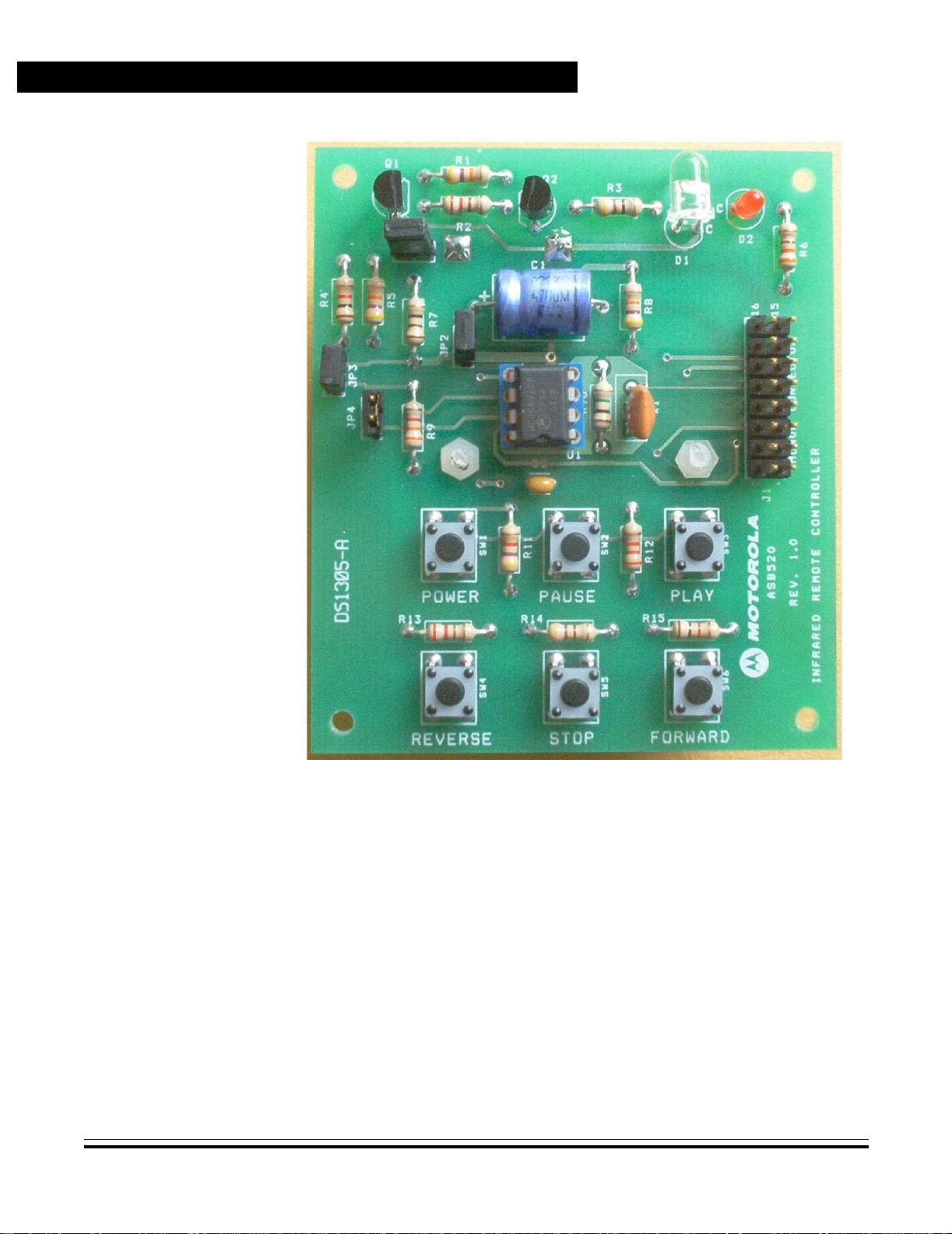
A few of the more noteworthy features of the reference PC board are listed as
follows:
• 8-pin MC68HC908QT2 microcontroller
• Infrared LED and driver
• Visible LED to show activity
• Six user push buttons
• MON08 programming interface for in-circuit FLASH programming
• Battery holder for 3-AA cells
• Microcontroller current monitor jumper block
A photograph of the reference PC board appears in Figure 1-1.
Key items can be found in the following locations in this manual:
• Setup instructions are found in 1.3 Setup Guide.
• Schematics are found in 4.2 Schematic.
• Pin assignments for MON08 connector J1 are shown in Table 3-1.
MON08 Pin Assignments.
• User interfaces are described in 2.3 LEDs.
• For those interested in the design aspects of the reference PC board’s
circuitry, a description is provided in Section 5. Design
Considerations.
• System testing, hardware and software, are described in detail in
Section 6. System Testing.
Using the ASB520 MC68HC908QT2 Based Infrared Remote Control Reference PC Board DRM045
MOTOROLA Introduction and Setup 7
For More Information On This Product,
Go to: www.freescale.com
Page 8
Introduction and Setup
nc...
I
Freescale Semiconductor, Inc.
cale Semiconductor,
Frees
1.3 Setup Guide
Figure 1-1. MC68HC908QT2 IR Reference PC Board Photograph
Setup for the reference design PC board can be broken into two parts.
• The first is normal user operation mode.
• The second is MC68HC908QT2 FLASH programming configuration.
FLASH programming is explained in Section 6. System Testing.
It is assumed for user operational mode, the MC68HC908QT1 has been
programmed with the remote control program. If not, refer to Section 6.
System Testing for FLASH programming information.
Figure 2-1. PC Board shows the locations of the various jumper blocks and
MON08 connector.
DRM045 Using the ASB520 MC68HC908QT2 Based Infrared Remote Control Re ference PC Board
8 Introduction and Setup MOTOROLA
For More Information On This Product,
Go to: www.freescale.com
Page 9

Freescale Semiconductor, Inc.
For user operation mode, shorting jumpers need to be installed to jumper
blocks JP1–JP4. Shorting jumper block JP1 is not necessary if the small PC
board trace under jumper block JP1, on the bottom side of the PC board, has
not been cut for microcontroller current monitoring.
Installation of 3-AA Alkaline batteries into the battery holder mounted on the
bottom of the PC board is also required for setup. Note battery polarity on the
battery holder. The PC board is now ready for use as an infrared remote
control.
nc...
I
Introduction and Setup
Setup Guide
cale Semiconductor,
Frees
Using the ASB520 MC68HC908QT2 Based Infrared Remote Control Reference PC Board DRM045
MOTOROLA Introduction and Setup 9
For More Information On This Product,
Go to: www.freescale.com
Page 10

Introduction and Setup
nc...
I
Freescale Semiconductor, Inc.
cale Semiconductor,
Frees
DRM045 Using the ASB520 MC68HC908QT2 Based Infrared Remote Control Re ference PC Board
10 Introduction and Setup MOTOROLA
For More Information On This Product,
Go to: www.freescale.com
Page 11

Freescale Semiconductor, Inc.
Designer Reference Manual — DRM045
Section 2. Operational Description
2.1 Introduction
The following subsections describe the operation of the ASB520,
MC68HC908QT2 infrared remote control reference design system. LEDs,
switches, jumper blocks and FLASH programmer headers, and current monitor
jumper block are described here. Figure 2-1 shows the locations of these
nc...
I
items.
cale Semiconductor,
Frees
2.2 Push Buttons
There are six push button switches resident on the lower portion of the
reference PC board. They are labeled as switches SW1–SW6 on the PC board
schematic. Each button has a dedicated function. The switches are labeled as
POWER, PAUSE, PLAY, REVERSE, STOP, and FORWARD. These labels
describe the button’s operation function related to control of a DVD player.
2.3 LEDs
There are two LEDs located in the upper right hand corner of the PC board. Th e
LED labeled D1 is an infrared LED and the one labeled D2 is a visible red LED
and is used to show system activity.
2.3.1 Red Activity Indicator LED
D2 is a visible red LED and is used to show IR LED activity. It blinks as long
any push button is depressed
2.3.2 Infrared LED
D1 is an infrared LED. It is modulated to control the DVD.
Using the ASB520 MC68HC908QT2 Based Infrared Remote Control Reference PC Board DRM045
MOTOROLA Operational Description 11
For More Information On This Product,
Go to: www.freescale.com
Page 12

Freescale Semiconductor, Inc.
Operational Description
JP1
JP2
nc...
I
JP3
J1
JP4
cale Semiconductor,
Frees
Figure 2-1. PC Board
DRM045 Using the ASB520 MC68HC908QT2 Based Infrared Remote Control Re ference PC Board
12 Operational Description MOTOROLA
For More Information On This Product,
Go to: www.freescale.com
Page 13

nc...
I
cale Semiconductor,
Frees
Freescale Semiconductor, Inc.
2.4 Header and Jumpers Blocks
There is one 16-pin header (2 x 8-pin), J1, and four 2-pin jumper blocks,
JP1–JP4, on the PC board. See Figure 2-1 for their locations on the PC board.
The header and jumper functions are described as follows.
J1: Jumper block J1 is used to program the MC68HC908QT2, located in
the center of the PC board. The connections to this board follow the
standard MON08 connector scheme. It is also used to put the ASB520
system into test mode. In a production environment, J1 could be
replaced by a “bed of nails” test fixture to reduce PC board parts costs.
JP1: Jumper block JP1 is on the PC board measure the current consumed
by the microcontroller. Its primary purpose is to measure stop current of
the microcontroller. A small trace on the bottom of the PC board must
be cut to use this feature. When using this feature to measure stop
current you should remove shorting jumper JP2. Removing the shunt
from JP2 removes the system’s 470 µF bulk capacitor. Removing that
capacitor will improve accuracy of the current measurement, as large
capacitors have leakage current associated with them. Select the
lowest voltage rating bulk capacitor for your circuit as possible because
lower voltage rated ones tend to have less leakage than higher voltage
ones for a given capacitance value.
JP2: Jumper block JP2 disconnects the bulk capacitor during FLASH
programming and optionally during stop current monitoring. The value
of the capacitor is large enough to cause power switching issues when
using the Cyclone programmer. During the programming procedure,
the Cyclone programmer cycles power to the target PC board. Large
value bulk capacitors greater than approximately 100 µF present
excessive currents to the Cyclone programmer and interfere with the
POR circuit of the target’s microcontroller as voltage on larger
capacitance devices do not discharge fast enough during voltage
cycling.
The purpose for the bulk capacitor is two fold: First is tends to help lower
the effects of the battery’s internal resistance during periods of high
current demands while the IR LED is being modulated. This is a
particular benefit toward the battery’s end of life period, when its internal
resistance is increasing. Second, if a system uses RAM to store user
information, the bulk capacitor will retain voltage to the microcontroller
during battery changes.
Operational Description
Header and Jumpers Blocks
JP3: Jumper block JP3 disconnects pullup resistor, R9, during FLASH
programming.
JP4: Jumper block JP4 disconnects LED drive circuitry during FLASH
programming.
Using the ASB520 MC68HC908QT2 Based Infrared Remote Control Reference PC Board DRM045
MOTOROLA Operational Description 13
For More Information On This Product,
Go to: www.freescale.com
Page 14

Operational Description
2.5 Microcontroller Current Monitor Jumper Block
nc...
I
Freescale Semiconductor, Inc.
Jumper block JP1 is intended as a connection on the PC board to measure the
stop current of the MC68HC908QT2. To use the feature, you must cut the small
PC board trace located on the bottom side of the PC board between the two
pins of the jumper block. After cutting the trace, and when not using an amp
meter to measure system current a shunt must be installed on JP1.
cale Semiconductor,
Frees
DRM045 Using the ASB520 MC68HC908QT2 Based Infrared Remote Control Re ference PC Board
14 Operational Description MOTOROLA
For More Information On This Product,
Go to: www.freescale.com
Page 15

Designer Reference Manual — DRM045
3.1 Introduction
nc...
3.2 16-Pin Connector J1
I
Freescale Semiconductor, Inc.
Section 3. Pin Description
There is one connector resident on the control board, labeled J1. It is the
MON08 connector. The following subsection describes signals on connector
J1.
Signals to and from the MON08 connector are grouped together on 16-pin
(2 x 8-pin) ribbon cable connector J1. Pin assignments for connector J1 are
shown in Table 3-1. In a production environment, J1 could be replaced by a
“bed of nails” test fixture to reduce PC board parts costs.
cale Semiconductor,
Frees
Table 3-1. MON08 Pin Assignments
Pin Number Function
1, 3, 4, 5, 7, 9, 11,14, 16 No connect
2GND
(PTA2)
6
8COM (PTA0)
10 MOD1 (PTA4)
12 MOD0 (PTA1)
13 OSC1 (PTA5)
15
V
TST
V
DD
Using the ASB520 MC68HC908QT2 Based Infrared Remote Control Reference PC Board DRM045
MOTOROLA Pin Description 15
For More Information On This Product,
Go to: www.freescale.com
Page 16

Pin Description
nc...
I
Freescale Semiconductor, Inc.
cale Semiconductor,
Frees
DRM045 Using the ASB520 MC68HC908QT2 Based Infrared Remote Control Re ference PC Board
16 Pin Description MOTOROLA
For More Information On This Product,
Go to: www.freescale.com
Page 17

Freescale Semiconductor, Inc.
Designer Reference Manual — DRM045
4.1 Introduction
Schematic and parts list detail are documented in this section.
4.2 Schematic
Section 4. Schematic and Parts List
nc...
I
cale Semiconductor,
Frees
A schematic of the reference design PC board appears in Figure 4-1. Unless
otherwise specified, capacitor values are in microfarads, resistor values are in
ohms. All resistors are specified as 1/4-watt ± 5%, and interrupted lines coded
with the same letters are electrically connected.
Using the ASB520 MC68HC908QT2 Based Infrared Remote Control Reference PC Board DRM045
MOTOROLA Schematic and Parts List 17
For More Information On This Product,
Go to: www.freescale.com
Page 18

Schematic and Parts List
Vbat
nc...
I
Freescale Semiconductor, Inc.
2N3906
Q2
R2
330
R1
47K
R4
JP4
PTA0
8
Vss
Q1
12
1 2
7
2N3904
1K
IR_DISC
IR_LED
D1
R3
47
R6
470
D2
RED
R5
47K
PTA1_ATD1
PTA2
5
6
cale Semiconductor,
Frees
PTA2/IRQ/KBI2
PTA1/AD1/TCH1/KBI1
PTA0/AD0/TCH0/KBI0
SW_DISC
JP3
U1
1
Vdd
PTA5
PTA5/OSC1/AD3/KBI5
Vdd
2
R10
10M
16MHz
X1
Vdd
R7
Vbat
JP1
1 2
12
PTA4/OSC2/AD2/KBI4
3
4
PTA4
C2
JP2
10
CAP_DISC
12
Idd_TEST
+-
NITRON_8_PIN_ADC
PTA3/RST/KBI3
R8
Vdd
0.1
12
+
1 2
C1
Vdd
47K
470uF
12
R9
3.3K
1 2
POWER
R11
4.7K
SW1
PAUSE
PTA1_ATD1
SW2
J1
13579
R12
2.2k
PLAY
SW3
PTA1_ATD1
PTA0
PTA2
PTA4
864
2
135791113
111315 16
R15
1k
FWD
SW6
1412108642
141210
15 16
MON08 CONNECTOR
Vdd
PTA5
R14
470
STOP
SW5
R13
REV
220
SW4
Figure 4-1. ASB520 PC Board Schematic
BAT1
BATTERY
DRM045 Using the ASB520 MC68HC908QT2 Based Infrared Remote Control Reference PC Board
18 Schematic and Parts List MOTOROLA
For More Information On This Product,
Go to: www.freescale.com
Page 19
nc...
I
cale Semiconductor,
Frees
Freescale Semiconductor, Inc.
Schematic and Parts List
Parts List
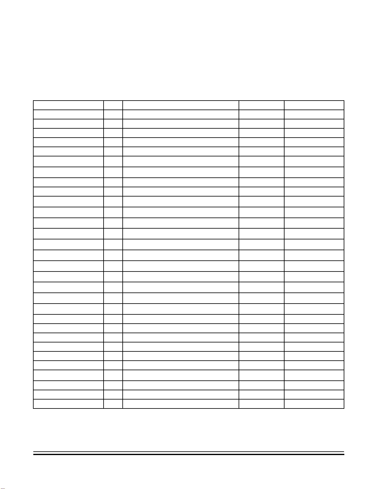
4.3 Parts List
The following parts list describes the parts content for the IR reference PC
board.
Table 4-1. Reference PC Board Parts List
Designators Qty. Description Manufacturer Part Number
BAT1 1 3-AA Battery Holder Digi-Key 2464K-ND
C1 1 470 µF Cap@6.3WV Digi-Key P5508-ND
C2 1 0.1 µF Capacitor Digi-Key 399-2127-ND
D1 1 Infrared LED Digi-Key 160-1061-ND
D2 1 Red LED Digi-Key 160-1061-ND
J1 1
JP1–JP4 4
Q1 1 2N3904 Digi-Key 2N3904-ND
Q2 1 2N3906 Digi-Key 2N3906-ND
R1, R8, R5 3
R3 1
R4, R15 2
R13 1
R2 1
R6, R14 2
R7 1
R9 1
R11 1
R10 1
R12 1
SW1–SW6 6 Momentary Push Button Switch Digi-Key CKN90 09-ND
U1 1 Nitron 8-pin DIP with A/D and 1.5K FLASH Digi-Key MC68HC908QT1CP
X1 1 16.00 MHz Resonator Digi-Key X908-ND
No Designator (optional) 1 8-pin socket for U1 Digi-Key A400-ND
No Designator 1 2-56 x 3/8” nylon screw Any Any
No Designator 1 2-56 nylon nut Any Any
No Designator 1
No Designator 1 ASB520 Bare PCB DS Electronics ASB520
No Designator 4 Shunts for JP1–JP4 Digi-Key S9000-ND
No Designator 3 AA Alkaline Battery Any Any
2 x 8 Pin Header
2 Pin Header
47K Ohm Resistor
47 Ohm Resistor
1K Ohm Resistor
220 Ohm Resistor
330 Ohm Resistor
470 Ohm Resistor
10 Ohm Resistor
3.3K Ohm Resistor
4.7K Ohm Resistor
1 Meg Ohm Resistor
2.2K Ohm Resistor
Tape, double-sided foam 1/8” x 1”
(1)
(1)
(2)
(2)
(2)
(2)
(2)
(2)
(2)
(2)
(2)
(2)
(2)
(3)
Digi-Key
Digi-Key
Digi-Key 47QBK-ND
Digi-Key 47QBK-ND
Digi-Key 1.0KQBK-ND
Digi-Key 220QBK-ND
Digi-Key 330QBK-ND
Digi-Key 470QBK-ND
Digi-Key 10QBK-ND
Digi-Key 3.3KQBK-ND
Digi-Key 4.7KQBK-ND
Digi-Key 1.0MQBK-ND
Digi-Key 2.2KQBK-ND
Digi-Key 3M4008-ND
S2211-36-ND
S1211-36-ND
(1)
(1)
1. Shipped in strips of 36 x 1 or 36 x 2. Cut to length.
2. All resistors are 1/4 W with a tolerance of 5% unless otherwise noted.
3. Cut to size.
Using the ASB520 MC68HC908QT2 Based Infrared Remote Control Reference PC Board DRM045
MOTOROLA Schematic and Parts List 19
For More Information On This Product,
Go to: www.freescale.com
Page 20

Schematic and Parts List
nc...
I
Freescale Semiconductor, Inc.
cale Semiconductor,
Frees
DRM045 Using the ASB520 MC68HC908QT2 Based Infrared Remote Control Re ference PC Board
20 Schematic and Parts List MOTOROLA
For More Information On This Product,
Go to: www.freescale.com
Page 21

Freescale Semiconductor, Inc.
Designer Reference Manual — DRM045
Section 5. Design Considerations
5.1 Introduction
Microcontroller systems, in general, have a number of important design
considerations related to PC board layout and grounding considerations.
These design considerations are discussed in 5.2 Grounding, 5.3 Infrared
and Visible LED Drive Circuit, and 5.4 Switch Circuitry. A description of two
nc...
I
of the reference board’s major circuits are included in 5.3 Infrared and Visible
LED Drive Circuit and 5.4 Switch Circuitry.
cale Semiconductor,
Frees
5.2 Grounding
PC board layout is an important design consideration. In particular, ground
planes and how grounds are tied together influence noise immunity. To
maximize oscillator noise immunity, it is a good practice have ground plane
under the resonator, X1. One good grounding practice is to carry all of the
ground connections, in a star configuration, to a single point which could be the
power supply’s bulk capacitor or in this case, the battery ground terminal.
5.3 Infrared and Visible LED Drive Circuit
Figure 5-1 is the driver schematic, used to drive both LEDs on the PC board.
Because the microcontroller will not source or sink enough current to drive the
two LEDs, a discrete driver is necessary. This circuit uses two transistors. The
first transistor is a small signal NPN, followed by a small signal PNP transistor.
To PTA0
1 2
IR_DISC
JP4
12
R5
47K
Vbat
R1
47K
R2
330
R4
1K
Q1
2N3904
R6
470
Q2
2N3906
R3
47
RED
D2
D1
IR_LED
Figure 5-1. Infrared LED Drive Circuit
Using the ASB520 MC68HC908QT2 Based Infrared Remote Control Reference PC Board DRM045
MOTOROLA Design Considerations 21
For More Information On This Product,
Go to: www.freescale.com
Page 22

Design Considerations
5.4 Switch Circuitry
nc...
I
Freescale Semiconductor, Inc.
A logic 1 from port A, bit 0 will turn the NPN transistor on, driving its collector
low. The low level applied to the base of the PNP transistor, Q2, will drive its
emitter to collector into conduction, illuminating the two LEDs. Resistor R5 is in
place to guarantee that Q1 is biased off during initial power on and before the
microcontroller’s program has configured port A, bit 1 to behave as a digital
output.
A simple circuit is used to give the ability of reading several switches into an
A/D port. Figure 5-2 shows the circuit. This circuit has the advantage of using
only one I/O pin for the six switches. Using a switch matrix and the keyboard
interrupt pins is an alternative approach, but in this case would require a
microcontroller with more I/O pins.
Vdd
2
JP3
2
SW_DISC
1
1
cale Semiconductor,
Frees
R9
3.3K
POWER
PTA1_ATD1
SW1
PLAY
SW2
FWD
SW3
REV
SW6
PAUSE
SW5
STOP
SW4
Figure 5-2. Switch Circuitry
R11
4.7K
R12
2.2k
R15
1k
R14
470
R13
220
DRM045 Using the ASB520 MC68HC908QT2 Based Infrared Remote Control Re ference PC Board
22 Design Considerations MOTOROLA
For More Information On This Product,
Go to: www.freescale.com
Page 23
Freescale Semiconductor, Inc.
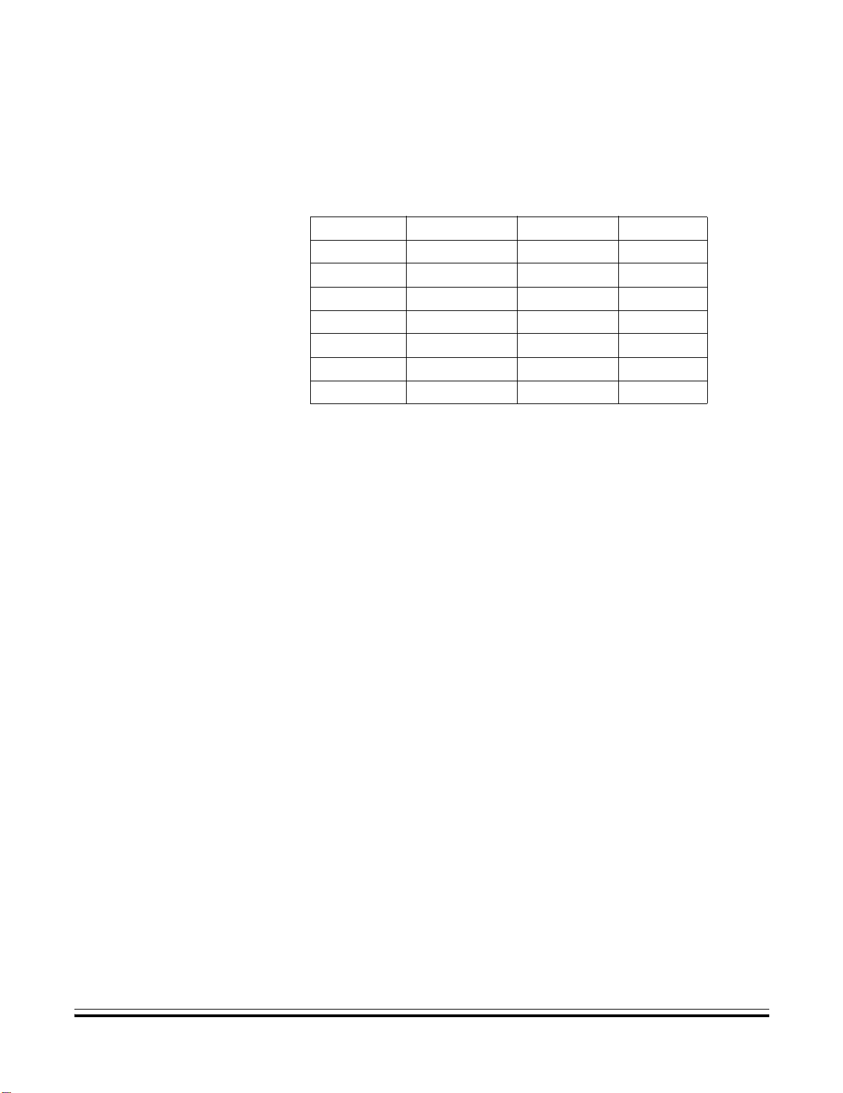
The spreadsheet in Table 5-1 gives the decimal values seen by the A/D, based
on which switch is depressed. Because the voltage from the switches is
ratiometric to V
nc...
I
Design Considerations
, power supply variation will have no effect on A/D readings.
DD
Table 5-1. Switch Input A/D Values
Switch Ideal Value Minus 6% Plus 6%
No switch 255 239.7 255
Powe r 170.5 160.3 180.7
Play 127.7 120 153.3
Forward 79.9 75.1 84.7
Reverse 40.8 38.4 43.3
Pause 14.8 13.9 15.6
Stop 0 0 0
Switch Circuitry
cale Semiconductor,
Frees
The ±6% values in Table 5-1 indicate worst case values, as the resistors used
in the design are ±5%. The software uses the minimum values from the table
to decode the switches.
Using the ASB520 MC68HC908QT2 Based Infrared Remote Control Reference PC Board DRM045
MOTOROLA Design Considerations 23
For More Information On This Product,
Go to: www.freescale.com
Page 24

Design Considerations
nc...
I
Freescale Semiconductor, Inc.
cale Semiconductor,
Frees
DRM045 Using the ASB520 MC68HC908QT2 Based Infrared Remote Control Re ference PC Board
24 Design Considerations MOTOROLA
For More Information On This Product,
Go to: www.freescale.com
Page 25

Freescale Semiconductor, Inc.
Designer Reference Manual — DRM045
Section 6. System Testing
6.1 Introduction
This section will first explain how to program the control program into FLASH
memory of the MC68HC908QT2 microcontroller. It will then, in detail, provide
functional testing of both hardware and user software for the ASB520 infrared
remote control reference design.
nc...
I
6.2 Hardware/Software Testing Summary
cale Semiconductor,
Frees
Because the PC board has minimal user interface, hardware testing will be
performed in stages.
6.3 FLASH Programming
The following steps are used to initially program the MC68HC908QT2:
Follow the P&E Microcomputer Systems, Inc. instructions to program the
MC68HC908QT2, with the remote control program file. The file name to
program into the device is ASB520.S19.
After FLASH programming is complete, disconnect the Cyclone’s ribbon cable
connected to J1 of the ASB520 PC board.
• First the control program will be programmed into the
MC68HC908QT2’s FLASH memory.
• The keyboard and red LED will be tested next.
• Finally, the ASB520 PC board will be used to control a DVD.
1. If installed, remove the batteries from the battery holder located on the
bottom of the PC board
2. Remove jumpers JP1–JP4.
3. Connect the P&E Microcomputer Systems, Inc. MON08 Cyclone’s
ribbon cable from the programmer to J1, noting the location of pin 1 on
J1.
In a production environment, the Cyclone Programmer can be setup so that a
single press of a button will initiate an automatic programming operation. The
Application Program would be pre-loaded into nonvolatile memory in the
Cyclone and no PC would need to be present during production programming.
Using the ASB520 MC68HC908QT2 Based Infrared Remote Control Reference PC Board DRM045
MOTOROLA System Testing 25
For More Information On This Product,
Go to: www.freescale.com
Page 26

System Testing
6.4 LED and Push Button Test Code
nc...
I
cale Semiconductor,
Frees
Freescale Semiconductor, Inc.
Test code is embedded in the ASB520 control program. This test code will test
the switches, LED drive circuitry and visible LED, D2. The infrared led, D1, is
illuminated, but you can’t see it. To run the test program, follow the next 12
steps:
1. Connect a jumper lead between pins 2 and 6 on connector J1.
2. Install shorting jumpers on jumper blocks JP1–JP4
3. Install 3-AA Alkaline batteries into the battery holder mounted on the
4. Depress the POWER switch, SW1. The red LED will flash once, delay
5. Depress the PAUSE switch, SW2. The red LED will flash twice, delay for
6. Depress the PLAY switch, SW3. The red LED will flash three times,
7. Depress the REVERSE switch, SW4. The red LED will flash four times,
8. Depress the STOP switch, SW5. The red LED will flash five t imes, delay
9. Depress the FORWARD switch, SW6. The red LED will flash six times,
10. Remove one battery. It doesn’t matter which one.
11. Remove the jumper lead from connector J1.
12. Replace the battery. (The system is now in user mode.)
bottom of the PC board. Note battery polarity on the battery holder.
When the last battery is installed, you will see the red LED, D2, flash five
times.
for approximately 2 seconds, flash again and continue that sequence
until the button is released. You will note the POWER button is SW1;
thus one blink. (This is the sequence for the remainder of the switches.)
approximately 2 seconds, flash twice again and continue that sequence
until the button is released.
delay for approximately 2 seconds, flash three times again and con tinue
that sequence until the button is released.
delay for approximately 2 seconds, flash four times again and continue
that sequence until the button is released.
for approximately 2 seconds, flash five times again and continue that
sequence until the button is released.
delay for approximately 2 seconds, flash six times again and continue
that sequence until the button is released.
All hardware except for the infrared diode, D1, has been tested at this point.
DRM045 Using the ASB520 MC68HC908QT2 Based Infrared Remote Control Re ference PC Board
26 System Testing MOTOROLA
For More Information On This Product,
Go to: www.freescale.com
Page 27

nc...
I
cale Semiconductor,
Frees
Freescale Semiconductor, Inc.
6.5 DVD Player Control Test
To test the infrared diode and the rest of the system in user mode, install a
music CD in the APEX model 1201 DVD player. Music CDs appear to respond
faster than video CD’s in this CD player.
To test the software, infrared diode and the rest of the ASM520 PC board,
follow these steps:
1. Configure the television and DVD player, following the instructions
2. On the DVD player, depress the power switch on the left side of th e DVD
3. On the DVD player, depress the OPEN/CLOSE switch located to the
4. Install a music CD in the APEX model 1201 DVD player.
5. Depress the OPEN/CLOSE switch on the DVD player to close the DVD
6. Wait for the yellow LED, located on the lower right hand end of the DVD
7. Point the ASB520 board with LED D1 toward the DVD player and
8. Verify the yellow MP3/CD JPEG LED turns off.
9. Point the ASB520 board with LED D1 toward the DVD player and again,
10. Point the ASB520 board with LED D1 toward the DVD player and
11. Point the ASB520 board with LED D1 toward the DVD player and
12. Point the ASB520 board with LED D1 toward the DVD player and
13. Point the ASB520 board with LED D1 toward the DVD player and
14. Point the ASB520 board with LED D1 toward the DVD player and
System Testing
DVD Player Control Test
provided with the DVD player.
player to turn it on.
right of the DVD drawer to open the DVD drawer.
drawer.
player, labeled MP3/CD JPEG to illuminate. It can take up to 10 seconds
on this DVD player.
depress the POWER switch on the ASB520 PC board to turn the DVD
player off.
press the POWER switch on the ASB520 PC board. In approximately 10
seconds, the MP3/CD JPEG LED will once again illuminate. This delay
is a function of the DVD player and not the controller.
depress the PLAY switch on the ASB520 PC board. The first song on
the CD will play.
depress the PAUSE switch on the ASB520 PC board. The music will
stop playing.
depress the PLAY switch on the ASB520 PC board. The music will
resume at the point it was paused.
depress the STOP switch on the ASB520 PC board. The music will stop
playing.
depress the PLAY switch on the ASB520 PC board. The music will
restart at the beginning of the song.
Using the ASB520 MC68HC908QT2 Based Infrared Remote Control Reference PC Board DRM045
MOTOROLA System Testing 27
For More Information On This Product,
Go to: www.freescale.com
Page 28

System Testing
nc...
I
Freescale Semiconductor, Inc.
15. Point the ASB520 board with LED D1 toward the DVD player and
16. Point the ASB520 board with LED D1 toward the DVD player and
17. Point the ASB520 board with LED D1 toward the DVD player and
18. Power to the DVD player may now be turned off by depress the power
This completes the hardware and software testing of the ASB520 infrared
remote controller system.
The controller is ready for use with the APEX model 1201 DVD player.
depress the REVERSE switch on the ASB520 PC board. The music will
back-up, at a high rate, until it reaches the beginning of the song, at
which time it will restart the song.
depress the FORWARD switch on the ASB520 PC board. The music will
play very fast.
depress the PLAY switch on the ASB520 PC board. The music will
resume at normal rate.
switch on the left side of the DVD player.
cale Semiconductor,
Frees
DRM045 Using the ASB520 MC68HC908QT2 Based Infrared Remote Control Re ference PC Board
28 System Testing MOTOROLA
For More Information On This Product,
Go to: www.freescale.com
Page 29

Freescale Semiconductor, Inc.
nc...
I
cale Semiconductor,
Frees
For More Information On This Product,
Go to: www.freescale.com
Page 30

Freescale Semiconductor, Inc.
HOW TO REACH US:
USA/EUROPE/LOCATIONS NOT LISTED:
Motorola Literature Distribution
P.O. Box 5405
Denver, Colorado 80217
1-800-521-6274 or 480-768-2130
JAPAN:
Motorola Japan Ltd.
SPS, Technical Information Center
3-20-1, Minami-Azabu, Minato-ku
Tokyo 106-8573, Japan
81-3-3440-3569
ASIA/PACIFIC:
Motorola Semiconductors H.K. Ltd.
Silicon Harbour Centre
2 Dai King Street
Tai Po Industrial Estate
nc...
I
Tai Po, N.T., Hong Kong
852-26668334
HOME PAGE:
http://motorola.com/semiconductors
cale Semiconductor,
Frees
Information in this document is provided solely to enable system and software implementers to use Motorola products.
There are no express or implied copyright licenses granted hereunder to design or fabric ate any integrated circuits or
integrated circuits based on the information in this document.
Motorola reserves the right to make changes without further notice to any pr od ucts her e in . Mot or ola ma kes no warranty ,
representation or guarantee regarding the suitability of its products for any particular purpose, nor does Motorola assume
any liability arising out of the application or use of any product or circuit, and specifically disclaims any and all liability,
including without limitation consequential or incidental damages. “Typical” parameters that may be provided in Motorola
data sheets and/or specification s can an d do vary in different applications and act ual p er formance may vary over time . All
operating parameters, i ncluding “Typicals”, must be v alidated for each customer application by customer’ s technical e xperts.
Motorola does not convey any license under its patent rights nor the rights of others. Motorola products are not desig ned ,
intended, or authorized for use as components in systems inte nded f or surgical implant int o the body, or other applications
intended to support or sustain life, or for any other application in which the failure of the Motorola product could create a
situation where personal injury or death may occur. Should Buyer purchase or use Motorola products for any such
unintended or unauthorized applicatio n, Buy er shall inde mnify and ho ld Motorol a and its offi cers, emplo y ees , subsidia ries,
affiliates, and distributors harmless against all claims, cost s, damages, and expens es, and reasonab le attorney f ees arising
out of, directly or indirectly, any claim of personal injury or death associated with such unintended or unauthorized use, even
if such claim alleges that Motorola was negligent regarding the design or manufacture of the part.
MOTOROLA and the Stylized M Logo are registered in the US Patent and Trademark Office. All other product or service
names are the property of their respective owners. Motorola, Inc. is an Equal Opportunity/Affirmative Action Employer.
© Motorola Inc. 2003
DRM045/D
Rev. 0
9/2003
For More Information On This Product,
Go to: www.freescale.com
 Loading...