

Page 1

MC1322x Simple Media Access
Controller (SMAC)
Reference Manual
Document Number: 22xSMACRM
Rev. 1.7
09/2011
Page 2

How to Reach Us:
Home Page:
www.freescale.com
E-mail:
support@freescale.com
USA/Europe or Locations Not Listed:
Freescale Semiconductor
Technical Information Center, CH370
1300 N. Alma School Road
Chandler, Arizona 85224
+1-800-521-6274 or +1-480-768-2130
support@freescale.com
Europe, Middle East, and Africa:
Freescale Halbleiter Deutschland GmbH
Technical Information Center
Schatzbogen 7
81829 Muenchen, Germany
+44 1296 380 456 (English)
+46 8 52200080 (English)
+49 89 92103 559 (German)
+33 1 69 35 48 48 (French)
support@freescale.com
Japan:
Freescale Semiconductor Japan Ltd.
Headquarters
ARCO Tower 15F
1-8-1, Shimo-Meguro, Meguro-ku,
Tokyo 153-0064, Japan
0120 191014 or +81 3 5437 9125
support.japan@freescale.com
Asia/Pacific:
Freescale Semiconductor Hong Kong Ltd.
Technical Information Center
2 Dai King Street
Tai Po Industrial Estate
Tai Po, N.T., Hong Kong
+800 2666 8080
support.asia@freescale.com
For Literature Requests Only:
Freescale Semiconductor Literature Distribution Center
P.O. Box 5405
Denver, Colorado 80217
1-800-521-6274 or 303-675-2140
Fax: 303-675-2150
LDCForFreescaleSemiconductor@hibbertgroup.com
Information in this document is provided solely to enable system and software implementers to use
Freescale Semiconductor products. There are no express or implied copyright licenses granted
hereunder to design or fabricate any integrated circuits or integrated circuits based on the information
in this document.
Freescale Semiconductor reserves the right to make changes without further notice to any products
herein. Freescale Semiconductor makes no warranty, representation or guarantee regarding the
suitability of its products for any particular purpose, nor does Freescale Semiconductor assume any
liability arising out of the application or use of any product or circuit, and specifically disclaims any
and all liability, including without limitation consequential or incidental damages. “Typical” parameters
that may be provided in Freescale Semiconductor data sheets and/or specifications can and do vary
in different applications and actual performance may vary over time. All operating parameters,
including “Typicals”, must be validated for each customer application by customer’s technical
experts. Freescale Semiconductor does not convey any license under its patent rights nor the rights
of others. Freescale Semiconductor products are not designed, intended, or authorized for use as
components in systems intended for surgical implant into the body, or other applications intended to
support or sustain life, or for any other application in which the failure of the Freescale Semiconductor
product could create a situation where personal injury or death may occur. Should Buyer purchase
or use Freescale Semiconductor products for any such unintended or unauthorized application,
Buyer shall indemnify and hold Freescale Semiconductor and its officers, employees, subsidiaries,
affiliates, and distributors harmless against all claims, costs, damages, and expenses, and
reasonable attorney fees arising out of, directly or indirectly, any claim of personal injury or death
associated with such unintended or unauthorized use, even if such claim alleges that Freescale
Semiconductor was negligent regarding the design or manufacture of the part.
ARM is the registered trademark of ARM Limited. ARM7TDMI-S is the trademark of ARM Limited.
IAR Systems, IAR Embedded Workbench, C-SPY, visualSTATE, From Idea to Target, IAR KickStart
Kit, IAR PowerPac, IAR YellowSuite, and IAR are trademarks or registered trademarks owned by IAR
Systems AB.
Copyright © 2007 IAR Systems AB.
Freescale™ and the Freescale logo are trademarks of Freescale Semiconductor, Inc. All other
product or service names are the property of their respective owners.
© Freescale Semiconductor, Inc. 2005, 2006, 2007, 2008, 2009, 2010, 2011. All rights reserved.
Page 3

Contents
About This Book
Audience . . . . . . . . . . . . . . . . . . . . . . . . . . . . . . . . . . . . . . . . . . . . . . . . . . . . . . . . . . . . . . . . . . . . iii
Organization . . . . . . . . . . . . . . . . . . . . . . . . . . . . . . . . . . . . . . . . . . . . . . . . . . . . . . . . . . . . . . . . . iii
Revision History . . . . . . . . . . . . . . . . . . . . . . . . . . . . . . . . . . . . . . . . . . . . . . . . . . . . . . . . . . . . . . iii
Definitions, Acronyms, and Abbreviations . . . . . . . . . . . . . . . . . . . . . . . . . . . . . . . . . . . . . . . . . iv
Chapter 1
MC1322x SMAC Introduction
1.1 Available Devices . . . . . . . . . . . . . . . . . . . . . . . . . . . . . . . . . . . . . . . . . . . . . . . . . . . . . . . . . . . . 1-2
1.2 Features. . . . . . . . . . . . . . . . . . . . . . . . . . . . . . . . . . . . . . . . . . . . . . . . . . . . . . . . . . . . . . . . . . . . 1-2
1.3 MCU Resource Requirements . . . . . . . . . . . . . . . . . . . . . . . . . . . . . . . . . . . . . . . . . . . . . . . . . . 1-3
1.4 Introducing BeeKit . . . . . . . . . . . . . . . . . . . . . . . . . . . . . . . . . . . . . . . . . . . . . . . . . . . . . . . . . . . 1-3
1.4.1 BeeKit Concepts . . . . . . . . . . . . . . . . . . . . . . . . . . . . . . . . . . . . . . . . . . . . . . . . . . . . . . . . . . 1-3
Chapter 2
MC1322x SMAC Software Architecture
2.1 MC1322x SMAC Block Diagram . . . . . . . . . . . . . . . . . . . . . . . . . . . . . . . . . . . . . . . . . . . . . . . 2-1
2.2 Hardware Support . . . . . . . . . . . . . . . . . . . . . . . . . . . . . . . . . . . . . . . . . . . . . . . . . . . . . . . . . . . . 2-2
2.3 Optional Modules . . . . . . . . . . . . . . . . . . . . . . . . . . . . . . . . . . . . . . . . . . . . . . . . . . . . . . . . . . . . 2-2
2.3.1 OTAP Module. . . . . . . . . . . . . . . . . . . . . . . . . . . . . . . . . . . . . . . . . . . . . . . . . . . . . . . . . . . . 2-2
2.3.2 Security Module . . . . . . . . . . . . . . . . . . . . . . . . . . . . . . . . . . . . . . . . . . . . . . . . . . . . . . . . . . 2-3
2.4 MC1322x SMAC Messages . . . . . . . . . . . . . . . . . . . . . . . . . . . . . . . . . . . . . . . . . . . . . . . . . . . . 2-3
2.4.1 Message Types . . . . . . . . . . . . . . . . . . . . . . . . . . . . . . . . . . . . . . . . . . . . . . . . . . . . . . . . . . . 2-4
2.4.2 Message State Machine . . . . . . . . . . . . . . . . . . . . . . . . . . . . . . . . . . . . . . . . . . . . . . . . . . . . 2-6
2.4.3 Message Constraints . . . . . . . . . . . . . . . . . . . . . . . . . . . . . . . . . . . . . . . . . . . . . . . . . . . . . . . 2-6
2.5 MC1322x SMAC Data Types. . . . . . . . . . . . . . . . . . . . . . . . . . . . . . . . . . . . . . . . . . . . . . . . . . . 2-7
2.5.1 message_t . . . . . . . . . . . . . . . . . . . . . . . . . . . . . . . . . . . . . . . . . . . . . . . . . . . . . . . . . . . . . . . 2-7
2.6 Generic Application Code Example . . . . . . . . . . . . . . . . . . . . . . . . . . . . . . . . . . . . . . . . . . . . . . 2-8
Chapter 3
MC1322x SMAC Primitives
3.1 Common Data Types . . . . . . . . . . . . . . . . . . . . . . . . . . . . . . . . . . . . . . . . . . . . . . . . . . . . . . . . . 3-1
3.1.1 callback_t . . . . . . . . . . . . . . . . . . . . . . . . . . . . . . . . . . . . . . . . . . . . . . . . . . . . . . . . . . . . . . . 3-1
3.1.2 FuncReturn_t . . . . . . . . . . . . . . . . . . . . . . . . . . . . . . . . . . . . . . . . . . . . . . . . . . . . . . . . . . . . 3-1
3.2 Core SMAC API. . . . . . . . . . . . . . . . . . . . . . . . . . . . . . . . . . . . . . . . . . . . . . . . . . . . . . . . . . . . . 3-2
3.2.1 ConfigureBuckRegulator . . . . . . . . . . . . . . . . . . . . . . . . . . . . . . . . . . . . . . . . . . . . . . . . . . . 3-2
3.2.2 DRVConfigureRTC . . . . . . . . . . . . . . . . . . . . . . . . . . . . . . . . . . . . . . . . . . . . . . . . . . . . . . . 3-3
3.2.3 MCPSDataRequest . . . . . . . . . . . . . . . . . . . . . . . . . . . . . . . . . . . . . . . . . . . . . . . . . . . . . . . . 3-3
3.2.4 MLMEDozeRequest . . . . . . . . . . . . . . . . . . . . . . . . . . . . . . . . . . . . . . . . . . . . . . . . . . . . . . . 3-4
3.2.5 MLMEEnergyDetect . . . . . . . . . . . . . . . . . . . . . . . . . . . . . . . . . . . . . . . . . . . . . . . . . . . . . . 3-5
3.2.6 MLMEGetChannelRequest . . . . . . . . . . . . . . . . . . . . . . . . . . . . . . . . . . . . . . . . . . . . . . . . . 3-6
3.2.7 MLMEGetPromiscuousMode. . . . . . . . . . . . . . . . . . . . . . . . . . . . . . . . . . . . . . . . . . . . . . . . 3-6
Freescale Semiconductor i
MC1322x SMAC Reference Manual, Rev. 1.7
Page 4

3.2.8 MLMEGetRficVersion . . . . . . . . . . . . . . . . . . . . . . . . . . . . . . . . . . . . . . . . . . . . . . . . . . . . . 3-7
3.2.9 MLMEHibernateRequest . . . . . . . . . . . . . . . . . . . . . . . . . . . . . . . . . . . . . . . . . . . . . . . . . . . 3-7
3.2.10 MLMELinkQuality. . . . . . . . . . . . . . . . . . . . . . . . . . . . . . . . . . . . . . . . . . . . . . . . . . . . . . . . 3-8
3.2.11 MLMEPAOutputAdjust . . . . . . . . . . . . . . . . . . . . . . . . . . . . . . . . . . . . . . . . . . . . . . . . . . . . 3-9
3.2.12 MLMEPHYResetIndication . . . . . . . . . . . . . . . . . . . . . . . . . . . . . . . . . . . . . . . . . . . . . . . . 3-10
3.2.13 MLMEPHYSoftReset. . . . . . . . . . . . . . . . . . . . . . . . . . . . . . . . . . . . . . . . . . . . . . . . . . . . . 3-10
3.2.14 MLMEPHYXtalAdjust. . . . . . . . . . . . . . . . . . . . . . . . . . . . . . . . . . . . . . . . . . . . . . . . . . . . 3-11
3.2.15 MLMERadioInit . . . . . . . . . . . . . . . . . . . . . . . . . . . . . . . . . . . . . . . . . . . . . . . . . . . . . . . . . 3-11
3.2.16 MLMERXDisableRequest . . . . . . . . . . . . . . . . . . . . . . . . . . . . . . . . . . . . . . . . . . . . . . . . . 3-12
3.2.17 MLMERXEnableRequest. . . . . . . . . . . . . . . . . . . . . . . . . . . . . . . . . . . . . . . . . . . . . . . . . . 3-12
3.2.18 MLMEScanRequest . . . . . . . . . . . . . . . . . . . . . . . . . . . . . . . . . . . . . . . . . . . . . . . . . . . . . . 3-13
3.2.19 MLMESetChannelRequest . . . . . . . . . . . . . . . . . . . . . . . . . . . . . . . . . . . . . . . . . . . . . . . . . 3-14
3.2.20 MLMESetPromiscuousMode . . . . . . . . . . . . . . . . . . . . . . . . . . . . . . . . . . . . . . . . . . . . . . . 3-15
3.2.21 MLMESetWakeupSource. . . . . . . . . . . . . . . . . . . . . . . . . . . . . . . . . . . . . . . . . . . . . . . . . . 3-15
3.2.22 MLMETestMode . . . . . . . . . . . . . . . . . . . . . . . . . . . . . . . . . . . . . . . . . . . . . . . . . . . . . . . . 3-16
3.3 Security - Module API . . . . . . . . . . . . . . . . . . . . . . . . . . . . . . . . . . . . . . . . . . . . . . . . . . . . . . . 3-17
3.3.1 CipherConfigure . . . . . . . . . . . . . . . . . . . . . . . . . . . . . . . . . . . . . . . . . . . . . . . . . . . . . . . . . 3-17
3.3.2 CipherEngineInit. . . . . . . . . . . . . . . . . . . . . . . . . . . . . . . . . . . . . . . . . . . . . . . . . . . . . . . . . 3-18
3.3.3 CipherMsg and CipherMsgU8 . . . . . . . . . . . . . . . . . . . . . . . . . . . . . . . . . . . . . . . . . . . . . . 3-19
3.3.4 DecipherMsg and DecipherMsgU8 . . . . . . . . . . . . . . . . . . . . . . . . . . . . . . . . . . . . . . . . . . 3-20
3.4 OTAP - Module API. . . . . . . . . . . . . . . . . . . . . . . . . . . . . . . . . . . . . . . . . . . . . . . . . . . . . . . . . 3-21
3.4.1 OTAP_data_indication_execute . . . . . . . . . . . . . . . . . . . . . . . . . . . . . . . . . . . . . . . . . . . . . 3-21
3.4.2 OTAP_execute . . . . . . . . . . . . . . . . . . . . . . . . . . . . . . . . . . . . . . . . . . . . . . . . . . . . . . . . . . 3-22
3.4.3 OTAP_Init . . . . . . . . . . . . . . . . . . . . . . . . . . . . . . . . . . . . . . . . . . . . . . . . . . . . . . . . . . . . . 3-23
3.5 Support Function API . . . . . . . . . . . . . . . . . . . . . . . . . . . . . . . . . . . . . . . . . . . . . . . . . . . . . . . . 3-24
3.5.1 ConfigureRfCtlSignals . . . . . . . . . . . . . . . . . . . . . . . . . . . . . . . . . . . . . . . . . . . . . . . . . . . . 3-24
3.5.2 SetEdCcaThreshold . . . . . . . . . . . . . . . . . . . . . . . . . . . . . . . . . . . . . . . . . . . . . . . . . . . . . . 3-25
3.5.3 SetComplementaryPAState . . . . . . . . . . . . . . . . . . . . . . . . . . . . . . . . . . . . . . . . . . . . . . . . 3-25
3.5.4 SetDemulatorMode. . . . . . . . . . . . . . . . . . . . . . . . . . . . . . . . . . . . . . . . . . . . . . . . . . . . . . . 3-26
3.5.5 SetPowerLevelLockMode . . . . . . . . . . . . . . . . . . . . . . . . . . . . . . . . . . . . . . . . . . . . . . . . . 3-27
3.5.6 RadioInit . . . . . . . . . . . . . . . . . . . . . . . . . . . . . . . . . . . . . . . . . . . . . . . . . . . . . . . . . . . . . . . 3-27
ii Freescale Semiconductor
MC1322x SMAC Reference Manual, Rev. 1.7
Page 5

About This Book
This guide provides a description of the Freescale MC1322x Simple Media Access Controller (MC1322x
SMAC).
Audience
This document is intended for application developers building IEEE 802.15.4 PHY compliant wireless
applications.
The MC1322x SMAC is incorporated in the Freescale BeeKit Wireless Connectivity Toolkit. The
incorporation of the MC1322x SMAC into BeeKit makes it easier for users to employ and customize the
MC1322x SMAC and associated applications.
The MC1322x SMAC is not the same SMAC used for the MC1319x and MC1321x. The primary
differences are as follows:
• MC1322x SMAC does not have blocking functions
• MC1322x SMAC has a new Radio Management module which allows management of multiple
messages depending on the application needs
• MC1322x file and directory structure are different
• MC1322x API is different
Organization
This document is organized into three (3) chapters.
Chapter 1 MC1322x SMAC Introduction — This chapter introduces the MC1322x SMAC
features and functionality.
Chapter 2 MC1322x SMAC Software Architecture — This chapter describes the MC1322x
SMAC software architecture.
Chapter 3 MC1322x SMAC Primitives — This chapter provides a detailed description of
MC1322x SMAC primitives.
Revision History
The following table summarizes revisions to this document since the previous release. (Rev 1.6)
Revision History
Location Revision
Chapter 3 Added new function
Freescale Semiconductor iii
MC1322x SMAC Reference Manual, Rev. 1.7
Page 6

Definitions, Acronyms, and Abbreviations
The following list defines the acronyms and abbreviations used in this document.
AES Advanced Encryption Standard
API Application Programming Interface
ASM Advanced Security Module
BDM debugger A debugger using the BDM interface for communication with the MCU. An
example is the P&E BDM Multilink debugger for HCS08
BDM Background Debug Module
CBC Cipher Block Chaining
CBC-MAC Cipher Block Chaining Message Authentication Code
CCM Counter with CBC-MAC
CTR Counter
dBm Decibels relative to one milliwatt.
EN End Node - Evaluation Boards
EVB Evaluation Boards
EVK Evaluation Kit
GUI Graphical User Interface
IDE Integrated Development Environment
MAC Medium Access Control
MAC2 Message Authentication Code
MCU MicroController Unit
NVM Non-volatile Memory
OTAP Over The Air Programming
PC Personal Computer
PCB Printed Circuit Board
S19 S - Record. 'S19' is the file extension used for the Freescale binary image format.
The S19 file encapsulates the binary image as a list of ASCII records. Each record
contains a length -, address -, data - and checksum field. The 16 bit address field
allows a memory space for up to 64 KB. The S19 can be generated with
CodeWarrior IDE and is the product from the linking process. S19 does not
contain additional information for a debugger (where to look for source files)
Safe Mode Boot The Embedded Bootloader boots up using safe default system values
SMAC Simple Media Access Controller
iv Freescale Semiconductor
MC1322x SMAC Reference Manual, Rev. 1.7
Page 7

Chapter 1
MC1322x SMAC Introduction
The Freescale MC1322x Simple Media Access Controller (MC1322x SMAC) is a simple ANSI C based
code stack available as sample source code. The MC1322x SMAC can be used for developing proprietary
RF transceiver applications using the Freescale MC1322x Platform in a Package (PiP). The MC1322x
SMAC is designed to work with the MC1322x MCUs. See Section 1.1, “Available Devices” for more
information.
The MC1322x SMAC is incorporated in the Freescale BeeKit Wireless Connectivity Toolkit. The
incorporation of the MC1322x SMAC into BeeKit makes it easier for users to employ and customize the
MC1322x SMAC and associated applications, see the MC1322x SMAC Demonstration Applications
User’s Guide (22xSMACDAUG) for more information on these applications.
To use any of the existing applications available in the MC1322x SMAC, users must first generate the
applications as projects in a BeeKit solution. For more information about BeeKit, BeeKit Projects, and
BeeKit Solutions, refer to the BeeKit Wireless Connectivity Toolkit User’s Guide (BKWCTKUG) and the
BeeKit on-line help.
The following is a list of MC1322x SMAC based demonstration applications:
•Wireless UART
• Connectivity
• Accelerometer
• Low Power Bell
• Generic Application
• Simple ZTC
• Repeater
• Weather Station
• OTAP Programmer
For more details on running the MC1322x SMAC demonstration applications, refer to the MC1322x
SMAC Demonstration Applications User’s Guide. (22xSMACDAUG)
For more details about the MC1322x device, refer to the appropriate MC1322x Reference Manual
(MC1322xRM) and/or Data Sheet (MC1322x).
MC1322x SMAC Reference Manual, Rev. 1.7
Freescale Semiconductor 1-1
Page 8

MC1322x SMAC Introduction
1.1 Available Devices
The MC1322x family is available as two part numbers. These device types differ only in their ROM
contents, all other device hardware, performance, and specifications are identical:
• MC13224V - this is the original version and is the generic part type.
— The MC13224V is intended for most IEEE 802.15.4 applications including MAC-based,
ZigBee-2007 Profile 1, and ZigBee RF4CE targets.
— It has a more complete set of peripheral drivers in ROM.
• MC13226V - this is a more recent version and is provided specifically for ZigBee-2007 Profile 2
(Pro) applications. Only the onboard ROM image has been changed to optimize ROM usage for
the ZigBee Pro profile and maximize the amount of available RAM for application use.
— The IEEE MAC/PHY functionality has been streamlined to include only that functionality
required by the ZigBee specification. The MAC functionality is 802.15.4 compatible.
— For a typical application, up to 20 kbytes more of RAM is available versus the M13224V
— Some drivers present in the MC13224 ROM have been removed and these include the ADC,
LCDfont, and SSI drivers. These drivers are still available as library functions, but now
compile into the RAM space.
— The Low Level Component (LLC) functionality has also been streamlined for the ZigBee
specification
NOTE
• When running the Freescale IEEE 802.15.4 MAC (or a related stack) on
the MC1322x platform, neither beaconing or GTS are supported.
• See the MC1322x Reference Manual (Document No MC1322xRM), for
information on using applications on these devices.
1.2 Features
• Compact footprint:
— Read Only - Code: ~5 Kb
— Read Only - Data: ~0.5 Kb
— Read Write - Data: ~2.5 Kb
• No blocking functions. (A blocking function means that the calling function will not return until
the routine is complete. Non-blocking functions return immediately, allowing core processing to
occur concurrently. A callback mechanism is included with the non-blocking functions to allow
synchronization.)
• Very-low power, proprietary, bi-directional RF communication link
• ANSI C source code targeted for the MC1322x core
• Easy-to-use sample application included
• Support for AES128 security for the transmission/reception of secured data in the SMAC packets
1-2 Freescale Semiconductor
MC1322x SMAC Reference Manual, Rev. 1.7
Page 9

MC1322x SMAC Introduction
1.3 MCU Resource Requirements
The MCU requires an external reference clock with allowed values from 13 MHz to 26 MHz.
Besides the memory resources, the SMAC uses the MACA module and thus all radio portions of the
MC1322x device. Depending on the demonstration, other resources are used such as the ADC, KBI, GPIO,
Timers and others.
1.4 Introducing BeeKit
The Freescale BeeKit Wireless Connectivity Toolkit is a comprehensive Codebase of wireless networking
libraries, application templates, and sample applications. The BeeKit Graphical User Interface (GUI), part
of the BeeKit Wireless Connectivity Toolkit, allows users to create, modify, and update various wireless
networking implementations.
The MC1322x SMAC is released in an independent Codebase that is part of the Freescale BeeKit Wireless
Connectivity Toolkit. To create a project for the MC1322x SMAC, users must employ the BeeKit
Codebase that contains the MC1322x SMAC code. For more information on BeeKit, refer to the BeeKit
Wireless Connectivity Toolkit User’s Guide (BKWCTKUG).
For more information on the Codebase as it applies to MC1322x SMAC, refer to the MC1322x SMAC
Demonstration Application User's Guide. (22xSMACDAUG)
1.4.1 BeeKit Concepts
This section highlights some basic BeeKit terms and concepts. Again, for a more detailed description of
BeeKit, refer to the BeeKit Wireless Connectivity Toolkit User’s Guide (BKWCTKUG).
Codebase A group of source files, configuration files, and generation rules that serve as a
repository from which all BeeKit demos, templates, and other applications are
generated.
Solution A group of projects which are linked to a specific folder within the file structure
of the computer and in this file structure, all other projects will generate their own
folders.
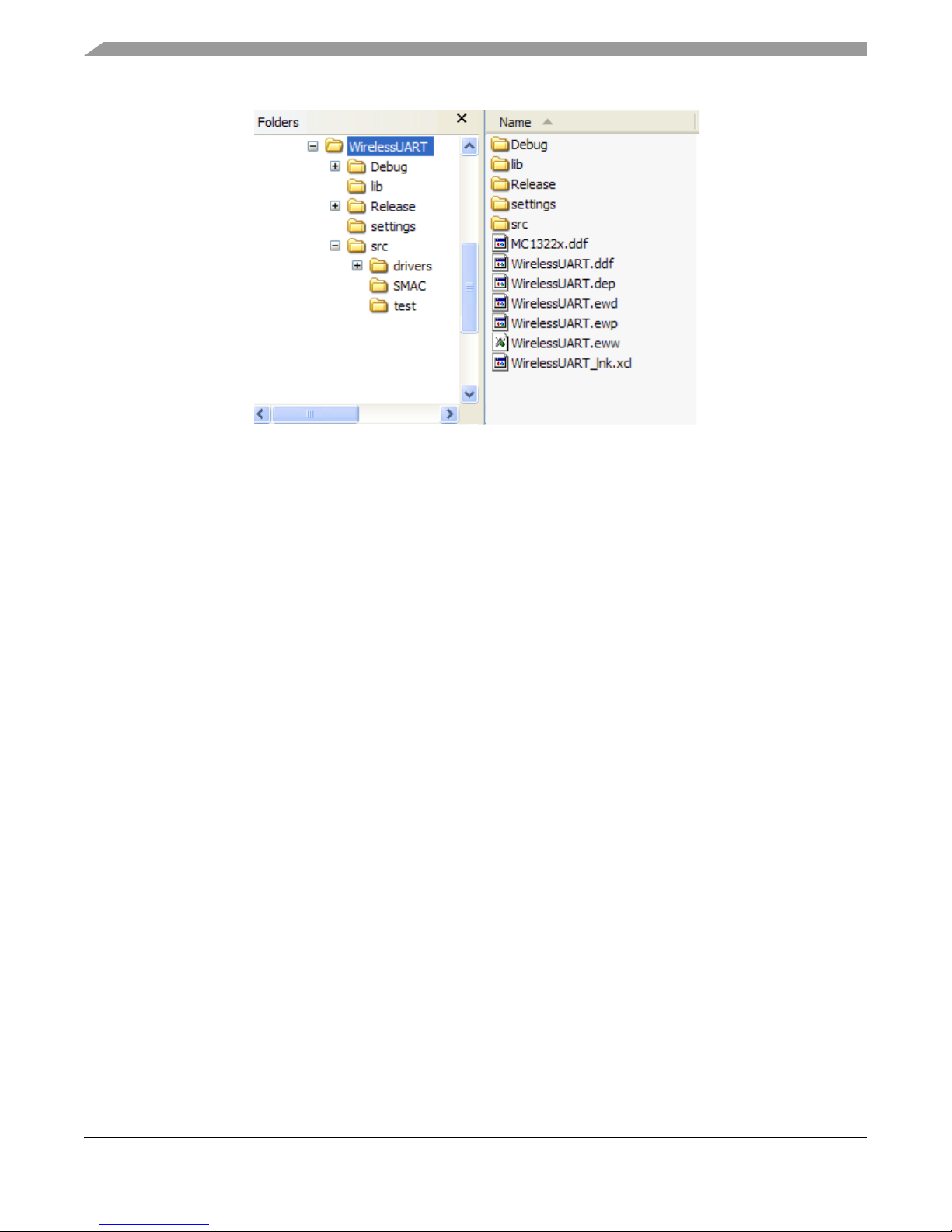
BeeKit Project A specific group of files in a directory tree that BeeKit can export for the
developer. An XML Project File in the tree describes the content and organization
of the project..
XML Project File A BeeKit generated XML file ready to import into CodeWarrior or IAR´s
Embedded Workbench IDE.
Figure 1-1 shows the folder structure of a typical project generated using MC1322x SMAC Codebase for
BeeKit.
Freescale Semiconductor 1-3
MC1322x SMAC Reference Manual, Rev. 1.7
Page 10
MC1322x SMAC Introduction
Figure 1-1. Example Project Folder Structure
1-4 Freescale Semiconductor
MC1322x SMAC Reference Manual, Rev. 1.7
Page 11
Chapter 2
MC1322x SMAC Software Architecture
This chapter describes the MC1322x SMAC software architecture. The MC1322x SMAC Codebase is
different than the S08 targeted SMAC Codebase. BeeKit can use the MC1322x SMAC codebase to create
projects to be compiled with the IAR Embedded Workbench IDE.
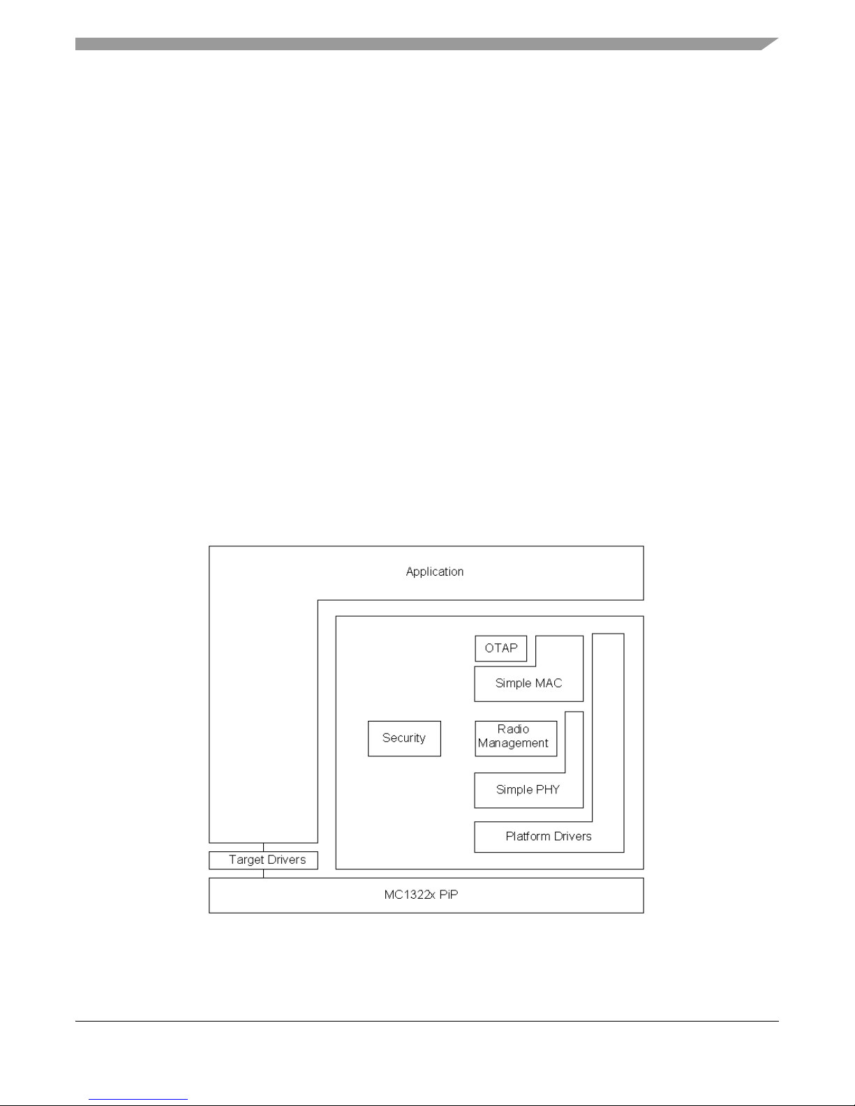
2.1 MC1322x SMAC Block Diagram
The Freescale MC1322x is a Platform in a Package (PiP) which integrates an RF transceiver modem,
MCU, AES ciphering and is fully compliant with the IEEE 802.15.4 standard. The MC1322x SMAC uses
its advanced, integrated functionality to provide a simple and high performance software package for IEEE
802.15.4 PHY wireless connectivity.
Figure 2-1 shows the MC1322x SMAC block diagram and the various MC1322x SMAC software
components. It is important to note the optional MC1322x SMAC modules:
• Security Module
• Over The Air Programmer (OTAP) Module
Figure 2-1. MC1322x SMAC Block Diagram
Freescale Semiconductor 2-1
MC1322x SMAC Reference Manual, Rev. 1.7
Page 12

MC1322x SMAC Software Architecture
Security, and OTAP modules and their APIs are included in the BeeKit project when the following
MC1322x SMAC BeeKit properties are set to True:
• Security Enabled
•OTAP Enabled
An API is implemented in the MC1322x SMAC as a C header file (.h) that allows access to the code. The
code includes the API to specific functions.
2.2 Hardware Support
This section describes the MC1322x SMAC hardware support
The MC1322x SMAC only supports the Freescale MC1322x transceivers and the MC1322x SMAC
projects only support the following Freescale development boards:
• MC1322x Sensor Node (MC13224 and MC13226)
• MC1322x Network Node (MC13224 and MC13226)
• MC1322x Low Power Node (MC13224 only)
• MC1322x USB (MC13224 only)
The changes required in the software to support any of the Freescale transceivers are generated
automatically by BeeKit after exporting a solution with the projects correctly configured. For more
information on exporting projects, see the BeeKit Wireless Connectivity Toolkit User’s Guide
(BKWCTKUG) and the BeeKit on-line help.
2.3 Optional Modules
2.3.1 OTAP Module
The Over the Air Programmer (OTAP) application allows users to update a board’s FLASH remotely
without a physical connection. Given an OTAP enabled application and an OTAP programmer, users can
replace an existing application on a board with a new application. Two boards are required for the OTAP
application:
• One board used as the OTAP Programmer
• One board used as the OTAP-enabled target
Freescale recommends that both of the images to be flashed are OTAP-enabled applications.
The following summarizes what users will accomplish with the OTAP application:
• On the OTAP Programmer Board:
— Download and run the OTAP Programmer software
— Download an OTAP-enabled application via the UART.
– The downloaded application must have its OTAP module property enabled when the project
is generated in BeeKit
— Any of the MC1322x development boards can be used as the OTAP Programmer
2-2 Freescale Semiconductor
MC1322x SMAC Reference Manual, Rev. 1.7
Page 13

MC1322x SMAC Software Architecture
• OTAP-enabled target Board (The board having its firmware updated.)
— Download and run an OTAP-enabled application on the board. The currently loaded
application will be replaced by the new application using the OTAP Programmer.
– The application being replaced must have its OTAP module property enabled when the
project is generated in BeeKit.
— Any of the MC1322x development boards can be used as an OTAP enabled target board.
2.3.2 Security Module
The security module is a software component that allows the ciphering and deciphering of messages
through its API. This section describes the procedure for implementing security in a MC1322x SMAC
application.
The MC1322x SMAC security management module allows implementation of wireless security
mechanisms. The MC1322x SMAC security module defines all functions required to cipher and decipher
the messages to be sent or received with the MC1322x SMAC on the MC1322x transceiver. The cipher
process is executed by the ASM module which implements the AES algorithm. It can perform CTR, CBC,
and CCM. CCM is a combination of CTR and CBC. For further details about the security implemented on
22x SMAC and the MC1322x, see Annex B of the IEEE standard 802.15.4-2003.
To enable security features, the security module must first be initialized, then the key and counter must be
set. After that, plain/cipher text can be ciphered/deciphered.
NOTE
The resulting ciphered/deciphered text is put on the same buffer where the
plain text is provided, for CBC and CCM modes which generate Message
Authentication Code, the provided buffer must also allocate 16 extra bytes
for the MAC.
The Security Module API is as follows:
FuncReturn_t CipherEngineInit(void)
FuncReturn_t CipherConfigure(cipher_mode_t u8CipherMode, cipher_key_t * pCipherKey,
ctr_value_t * pCtrValue)
FuncReturn_t CipherMsg (uint32_t * pu32CipherBuffer, uint8_t u8BufferLength)
FuncReturn_t DecipherMsg (uint32_t *pu32DecipherBuffer, uint8_t u8BufferLength)
FuncReturn_t CipherMsgU8(uint8_t *pu8CipherBuffer, uint8_t u8BufferLength)
FuncReturn_t DecipherMsgU8(uint8_t *pu8CipherBuffer, uint8_t u8BufferLength)
2.4 MC1322x SMAC Messages
This section describes the MC1322x SMAC messages, their types, operations and states. Send and receive
are basic functions of the MC1322x SMAC and they are implemented as messages. Energy detection and
radio idle time out are also implemented as messages. That is why messages are the core of the MC1322x
SMAC and it is important to explain the messages in detail both in how are they structured and how they
are processed and interfaced.
Freescale Semiconductor 2-3
MC1322x SMAC Reference Manual, Rev. 1.7
Page 14

MC1322x SMAC Software Architecture
Messages are processed by the Radio Management module. The Radio Management module has a circular
queue with the messages that need to be processed as a FIFO structure. The messages are attended in the
same order as they arrive.
Messages are added to the message queue using the following functions:
• MCPSDataRequest (for TX messages)
• MLMERXEnableRequest (for RX messages)
• MLMEEnergyDetect (for ED messages)
These functions call the Radio Management handle_new_message function.
Because the messages are processed by their states, the process_radio_msg function must also be called
periodically to run the message state machine.
2.4.1 Message Types
The MC1322x SMAC defines four types of messages:
• Reception (RX)
• Transmission (TX)
• Energy Detect (ED)
• Time out (TO)
These types of messages are directly related with radio operation. Messages types are defined at the
enumeration msg_type_t declared in the RadioManagement.h file. Each type of message has its own life
cycle. This cycle is defined by the different states that a message can take. The following code declared at
the RadioManagement.h file describes each message state:
2-4 Freescale Semiconductor
MC1322x SMAC Reference Manual, Rev. 1.7
Page 15

Transmit
typedef enum msg_tx_state_tag{
MSG_TX_RQST = initial_state_c,
MSG_TX_PASSED_TO_DEVICE,
MSG_TX_ACTION_STARTED,
MSG_TX_ACTION_COMPLETE_CHANN_BUSY,
MSG_TX_ACTION_COMPLETE_SUCCESS,
MSG_TX_ACTION_COMPLETE_FAIL,
MSG_TX_RQST_ABORT,
MSG_TX_ABORTED,
MAX_MSG_TX_STATE
}msg_tx_state_t;
Receive
typedef enum msg_rx_state_tag{
MSG_RX_RQST = initial_state_c,
MSG_RX_PASSED_TO_DEVICE,
MSG_RX_ACTION_STARTED,
MSG_RX_SYNC_FOUND,
MSG_RX_TIMEOUT_FAIL,
MSG_RX_ACTION_COMPLETE_SUCCESS,
MSG_RX_ACTION_COMPLETE_FAIL,
MSG_RX_RQST_ABORT,
MSG_RX_ABORTED,
MAX_MSG_RX_STATE
}msg_rx_state_t;
MC1322x SMAC Software Architecture
Energy Detect
typedef enum msg_ed_state_tag{
MSG_ED_RQST = initial_state_c,
MSG_ED_PASSED_TO_DEVICE,
MSG_ED_ACTION_COMPLETE_SUCCESS,
MSG_ED_ACTION_COMPLETE_FAIL,
MSG_ED_RQST_ABORT,
MSG_ED_ABORTED,
MAX_MSG_ED_STATE
}msg_ed_state_t;
Timeout
typedef enum msg_to_state_tag {
MSG_TO_RQST = initial_state_c,
MSG_TO_PASSED_TO_DEVICE,
MSG_TO_ACTION_COMPLETE_SUCCESS,
MSG_TO_ACTION_COMPLETE_FAIL,
MSG_TO_RQST_ABORT,
MSG_TO_ABORTED,
MC1322x SMAC Reference Manual, Rev. 1.7
Freescale Semiconductor 2-5
Page 16

MC1322x SMAC Software Architecture
MAX_MSG_TO_STATE
}msg_to_state_t;
2.4.2 Message State Machine
Messages passed to the Radio Management module are in an initial state of “requested”. Then they are
commanded to the MACA module in the MC1322x PiP to request that the radio perform the indicated
command. Then the Radio Management module processes the messages depending on the MACA
interrupts. The general model for the Messages State Machine is shown in Figure 2-2.
Figure 2-2. General Message State Machine
2.4.3 Message Constraints
Messages are not copied when they are attached to the messages queue. A pointer to the message is added
to the queue. An application developer must consider the following:
• Message data must not be modified during the period from putting the message in the message
queue until it is in a final state (The final state is any of the following states: action complete,
aborted or timeout occurs). Modifying data of a message before the message is on a final state
could cause a corrupted TX or RX.
• Message objects must be declared in a context such that they are not destroyed in the middle of
processing.
• Once a message goes to a final state, it is removed from the queue. If a message does not go to a
final state, the next message on the queue is not processed. For example, a reception message
without timeout does not allow the next message to be processed until the radio receives something
or the message is aborted.
• If a function (MCPSDataRequest, MLMERXEnableRequest or MLMEEnergyDetect) tries to add a message
to the queue and it is full, the return value will be the gFailNoResourcesAvailable_c error. When
calling this function, validate the return value to ensure that the message was added to the queue.
2-6 Freescale Semiconductor
MC1322x SMAC Reference Manual, Rev. 1.7
Page 17

MC1322x SMAC Software Architecture
The Radio Management module can catch and hold as many messages as the queue can hold at any given
time. The queue size is defined by the MAX_NUM_MSG declared in the RadioManagement.c file.
The process_radio_msg function must be called in order to process the messages. If this function is not
properly called, message processing will not work as expected. The application must periodically call
process_radio_msg at least until the message queue is empty.
2.5 MC1322x SMAC Data Types
The following list shows the fundamental data types and the naming convention used in MC1322x SMAC:
uint8_t Unsigned 8 bit definition
uint16_t Unsigned 16 bit definition
uint32_t Unsigned 32 bit definition
int8_t Signed 8 bit definition
int16_t Signed 16 bit definition
int32_t Signed 32 bit definition
Usage
These data types are used in the MC1322x SMAC project as well as in the applications projects. They are
defined in the typedef.h file.
2.5.1 message_t
This type defines a structure to store the messages information. It is located in the RadioManagement.h file
and is defined as follows:
typedef struct message_tag {
msg_status_t u8Status;
smac_pdu_t *pu8Buffer;
uint8_t u8BufSize;
callback_t cbDataIndication;
}message_t;
Members
u8Status The status of the message, it is formed by three bits for the message type and 5 bits
for the message state, this is defined with the msg_status_t type. There are four
types of messages: TX, RX, Time Out and Energy Detect. The application must
not write to this member, it is initialized when the message is passed to
MCPSDataRequest, MLMERXEnableRequest or MLMEEnergyDetect function
and updated by the process_radio_msg function.
* pu8Buffer A pointer to the data buffer to transmit or receive.
Freescale Semiconductor 2-7
MC1322x SMAC Reference Manual, Rev. 1.7
Page 18

MC1322x SMAC Software Architecture
u8BufSize Depending on the type of message this field means: the length of the buffer to be
transmitted; the maximum bytes to receive, at the end of the reception this field
stores the number of bytes received; the channel where the ED must be assessed.
cbDataIndication A pointer to the function that will be called when a message is completed, it can
be NULL
Usage
This data type is used by an application as follows:
1. The application declares as many message_t global variables as messages are required. For
example, the application can declare one for TX and one for RX
2. The application creates one data buffer for each message using the smac_pdu_size macro; for
example if the TX message will have 18 bytes of data the buffer would be declared as uint8_t
data[smac_pdu_size(18)];
3. The application initiates the message using the MSG_INIT macro. This macro is used as follow:
MSG_INIT([the message], [pointer to the data buffer], [callback pointer]); MSG_INIT is defined
in RadioManagement.h as:
#define MSG_INIT(msg, buff, cb) \
do { \
msg.pu8Buffer = (smac_pdu_t *)(buff); \
msg.cbDataIndication = cb; \
} while(0)
4. The application initializes the system, including the radio - MLMERadioInit() -.
5. The application requests a message transmission using the MCPSDataRequest function, or a
reception message using MLMERXEnableRequest function.
6. The application must call the process_radio_msg function periodically to process the messages.
Sample code is shown in the following section.
2.6 Generic Application Code Example
This section provides a sample generic application code snippet. For details about a specific function see
Chapter 3, MC1322x SMAC Primitives.
void a_simple_rx_callback_fn (void)
{
...
}
...
message_t a_TX_msg;
message_t a_RX_msg;
...
uint8_t dataTX[smac_pdu_size(TX SIZE)];
uint8_t dataRX[smac_pdu_size(RX SIZE)];
...
uint8_t main()
2-8 Freescale Semiconductor
MC1322x SMAC Reference Manual, Rev. 1.7
Page 19

{
...
/* Initiate the TX message */
MSG_INIT(a_TX_msg, &dataTX, NULL);
a_TX_msg.u8BufSize = TX_SIZE;
/* Initiate the RX message */
MSG_INIT(a_RX_msg, &dataRX, a_simple_rx_callback_fn);
a_RX_msg.u8BufSize = RX_SIZE;
...
/* Initiate Radio transceiver */
MLMERadioInit();
...
for(;;)
{
/* Process messages in the queue */
process_radio_msg();
...
/* Put in the queue a message to be transmitted */
if([Need to transmit a message]){
MCPSDataRequest(&a_TX_msg);
}
...
if([Need to receive a message]){
/* Put in the queue an RX message to put the transceiver in reception */
MLMERXEnableRequest(&a_RX_msg, TIME_OUT);
}
...
}
}
MC1322x SMAC Software Architecture
The following code snippets examples can be used for application development:
Validates if a TX message is complete:
((MSG_[Type of message]_ACTION_COMPLETE_SUCCESS == [message name].u8Status.msg_state) ||
(MSG_[Type of message]_ACTION_COMPLETE_FAIL == [message name].u8Status.msg_state))
This macro obtains the message type:
get_pmsg_type([pointer to the message])
This macro reads a message state:
get_pmsg_state([pointer to the message])
This macro reads a message buffer:
tx_pmsg_payload_buffer([Pointer to the message], [Position in the buffer])
This macro sets a message size:
set_pmsg_size([Pointer to the message], [Size in bytes])
Freescale Semiconductor 2-9
MC1322x SMAC Reference Manual, Rev. 1.7
Page 20

MC1322x SMAC Software Architecture
2-10 Freescale Semiconductor
MC1322x SMAC Reference Manual, Rev. 1.7
Page 21

Chapter 3
MC1322x SMAC Primitives
The following sections provide a detailed description of MC1322x SMAC primitives and common data
types associated with the three MC1322x SMAC APIs.
3.1 Common Data Types
This section highlights common data types used at MC1322x SMAC code.
3.1.1 callback_t
This is the type defined for general callbacks, that is a function that is that is passed as an argument to other
code. It allows the MC1322x SMAC API to call a subroutine (or function) defined in the application layer.
This type is defined for void functions that do not receive parameters.
typedef void(*callback_t)(void);
This type is used at MLMEHibernateRequest, MLMEDozeRequest, MLMEScanRequest functions and
also at objects of type message among others.
3.1.2 FuncReturn_t
This is the most common return type at the MC1322x SMAC functions. FuncReturn_t is an enumeration
defined as follows:
typedef enum FuncReturn_tag
{
gSuccess_c = 0,
gFailOutOfRange_c,
gFailNoResourcesAvailable_c,
gFailNoValidCondition_c,
gFailBusy_c,
gFailCorrupted_c,
gFailTest_c,
gAuthenticationFailed_c,
gAuthenticationPassed_c,
gFail_c
} FuncReturn_t;
MC1322x SMAC Reference Manual, Rev. 1.7
Freescale Semiconductor 3-1
Page 22

MC1322x SMAC Primitives
Returns
gSuccess General success return value.
gFailOutOfRange_c When one or more parameters are out of the valid range.
gFailNoResourcesAvailable_c When a needed resource to perform the requested action is not available
or is full.
gFailNoValidCondition_c When the requested action tries to put on an invalid state or tries to use
unavailable data. For example, this can happen when a module is not
correctly initialized.
gFailBusy_c If a hardware module is busy.
gFailCorrupted_c If a data corruption is detected while performing the requested action.
gFailTest_c Returned by ciphering functions when a function tries to perform a
ciphering/deciphering operation but the cipher engine has failed its
initialization.
gAuthenticationFailed_c When the ciphering process detect an authentication problem when
validation the authentication code value.
gAuthenticationPassed_c When the ciphering process success when validating the authentication
code value.
gFail_c Is the generic (all other failed cases) fail.
3.2 Core SMAC API
This section describes the MC1322x SMAC API functions.
3.2.1 ConfigureBuckRegulator
This primitive allows users to enable, disable or bypass the buck regulator.
Prototype
void ConfigureBuckRegulator(BuckTypes_t BuckRegState);
Arguments
BuckRegState The following arguments determine the required configuration of the buck
regulator:
BUCK_DISABLE
BUCK_BYPASS
BUCK_ENABLE
Returns
NONE
3-2 Freescale Semiconductor
MC1322x SMAC Reference Manual, Rev. 1.7
Page 23

MC1322x SMAC Primitives
Usage
Call ConfigureBuckRegulator with the required parameters.
NOTE
Do not enable the buck regulator when the operating voltage is lower than
2.5 volts. See the MC1322x Reference Manual for more details.
3.2.2 DRVConfigureRTC
This primitive allows configuring the Real Time Clock (RTC) to call back a function with a rate defined
by the RTC using the indicated reference clock.
Prototype
FuncReturn_t DRVConfigureRTC(crm_rtc_timingReference_t mTimingRef, uint32_t mTimeout,
callback_t pfUserCallbackFn);
Arguments
mTimingRef This argument indicates to reference clock to be used, it could be:
– gTimerRef_2Khz_c or
– gTimerRef_32Khz_c
mTimeout Time out referenced to the main clock. The value is on RTC ticks.
pfUserCallbackFn Is the pointer to the function that must be executed.
Returns
gFailOutOfRange_c If mTimingRef is not a valid reference or pfUserCallbackFn is equal to
NULL.
gFailNoValidCondition_c If the hardware does not get configured after some retries.
gSuccess_c If pfUserCallbackFn was successfully associated with the RTC interrupt.
gFail_c If it was not possible to associate pfUserCallbackFn with the RTC
interrupt.
Usage
Call DRVConfigureRTC with the required parameters.
3.2.3 MCPSDataRequest
This data primitive is used to send a packet.
Prototype
FuncReturn_t MCPSDataRequest (message_t *msg);
Freescale Semiconductor 3-3
MC1322x SMAC Reference Manual, Rev. 1.7
Page 24

MC1322x SMAC Primitives
Arguments
msg Pointer to the message to be transmitted.
Returns
gFailNoResourcesAvailable_c When there is no space in the messages queue.
gSuccess_c When the message can be added to the message queue.
Usage
• The application creates a message object
• The application associates a buffer to be transmitted with such message object
• Calls MCPSDataRequest() passing the message as parameter. Success response means that the
message has been added to the message queue, to validate the successful transition of the message
check the [msg].u8Status.msg_state
• Ensure that the process_radio_msg() is called because this function processes the pending
messages
This function does not perform blocking which is different than previous SMAC versions.
NOTE
Consider all the possible messages states as explained in chapter two to
implement the proper logic. Example, if the transmission was not successful
the application may want to transmit again like in the following code:
...
if(MSG_TX_ACTION_COMPLETE_FAIL == [The TX message].u8Status.msg_state) {
MCPSDataRequest([Pointer to the TX message]);
}
...
3.2.4 MLMEDozeRequest
Doze request allow the user to put the SoC Doze Mode. Review the appropriate MC1322x Reference
Manual for details regarding low power modes.
Prototype
FuncReturn_t MLMEDozeRequest(crmSleepCtrl_t SleepCtl);
Arguments
SleepCtl A structure of type crmSleepCtrl_t.
typedef struct
{
uint8_t sleepType:1;
uint8_t ramRet:2;
uint8_t mcuRet:1;
uint8_t digPadRet:1;
pfCallback_t pfToDoBeforeSleep;
3-4 Freescale Semiconductor
MC1322x SMAC Reference Manual, Rev. 1.7
Page 25

MC1322x SMAC Primitives
}crmSleepCtrl_t;
Returns
gFailNoValidCondition_c When there is no wakeup source configured.
gSuccess_c If the action is performed.
Usage
• Configures a wakeup source using MLMESetWakeupSource
• Ensure there is and assigned interrupt handler if needed (CrmAssignHandler can be used)
• Call MLMEDozeRequest
3.2.5 MLMEEnergyDetect
This call starts an energy detect (ED)/ Clear Channel Assessment (CCA) cycle and returns the energy value
for a given channel. This function receives a message as a parameter and shall be treated similar to a TX
or RX message. When an ED message goes to a successful final state, the energy detect value can be read
from the data buffer of the message. To properly process an ED message as well as a TX or RX message,
process_radio_msg must be periodically called, at least until all the messages in the message queue are
empty.
Energy detect values range from 0x00 to 0xFF.
0x00 The channel has practically no activity
0xFF The channel has heavy traffic and is very busy
Prototype
FuncReturn_t MLMEEnergyDetect (message_t *msg, channel_num_t u8channel);
Arguments
msg Pointer to the ED message.
u8channel The channel to be assessed. Valid values are from gChannel11_c to
gChannel26_c.
Returns
gFailOutOfRange_c If msg is a NULL value.
gFailNoResourcesAvailable_c When there is no space in the messages queue.
gSuccess_c When the message can be added to the message queue.
Usage
• Create a message object
• Associate a buffer with such message object, this buffer will used to store the energy detect value.
Use the macro MSG_INIT
Freescale Semiconductor 3-5
MC1322x SMAC Reference Manual, Rev. 1.7
Page 26

MC1322x SMAC Primitives
• Set the message type to energy detect by using [msg].u8Status.msg_type = ED;
• Call MLMEEnergyDetect() passing the message and the channel to be asses as parameters.
Success response means that the message has been added to the message queue, to validate the
successful transition of the message check the [msg].u8Status.msg_state
• Ensure that the process_radio_msg() is called since this function processes the pending messages
• When the message is on a MSG_ED_ACTION_COMPLETE_SUCCESS state, read the energy
detect value at [msg].pu8Buffer->u8Data[0].
This function does not perform blocking which is different than previous SMAC versions.
NOTE
To perform energy detect on two or more channels use the
MLMEScanRequest function. See the MLMEScanRequest description for
more details.
3.2.6 MLMEGetChannelRequest
This function returns the current channel, if an error is detected it returns 255.
Prototype
uint8_t MLMEGetChannelRequest (void);
Arguments
None.
Returns
gChannel11_c to gChannel26_c The current RF channel.
0xFF If current channel could not be detected
Usage
Call MLMEGetPromiscuousMode.
3.2.7 MLMEGetPromiscuousMode
This function returns the current state of promiscuous mode.
Prototype
bool_t MLMEGetPromiscuousMode(void);
Arguments
None.
3-6 Freescale Semiconductor
MC1322x SMAC Reference Manual, Rev. 1.7
Page 27

MC1322x SMAC Primitives
Returns
TRUE If promiscuous mode is active.
FALSE If promiscuous mode is inactive.
Usage
Call MLMEGetPromiscuousMode.
3.2.8 MLMEGetRficVersion
This function is used to read the version number of different hardware and software modules inside the
MC1322x.
Prototype
FuncReturn_t MLMEGetRficVersion(Versioned_Entity_t Entity, uint32_t *Buffer);
Arguments
Entity The module for which the version is required. The actual possible values are:
– HW_MACA_MC1322X_ID
– SW_SMAC_VERSION
– SW_BOOTSTRAP_VERSION
Buffer A pointer to the buffer where the version will be written.
Returns
gFailOutOfRange_c If the requested Entity is not part of the stored ones.
gSuccess_c If the action is performed.
Usage
• Declares a variable to store the version.
• Calls the MLMEGetRficVersion() passing the required Entity identifier and the pointer to store the
version.
3.2.9 MLMEHibernateRequest
This call places the radio into Hibernate mode. Refer to the MC1322x Reference Manual for more
information on the operation modes. This low power mode retains the 96Kb of RAM. If no fail is returned,
gSuccess_c is returned after the system wakes up.
Prototype
FuncReturn_t MLMEHibernateRequest(uint8_t u8HibClock, crmSleepCtrl_t SleepCtl);
Freescale Semiconductor 3-7
MC1322x SMAC Reference Manual, Rev. 1.7
Page 28

MC1322x SMAC Primitives
Arguments
u8HibClock Selects the clock to be used while hibernating. The possible values for this
argument are: gXtal32khz_c and gRingOsc2khz_c.
SleepCtl A structure of type crmSleepCtrl_t.
typedef struct
{
uint8_t sleepType:1;
uint8_t ramRet:2;
uint8_t mcuRet:1;
uint8_t digPadRet:1;
pfCallback_t pfToDoBeforeSleep;
}crmSleepCtrl_t;
Returns
gFailNoValidCondition_c When there is no wakeup source configured.
gFailOutOfRange_c When the u8HibClock argument is not a valid value.
gSuccess_c In any other case.
Usage
• Configures a wakeup source using MLMESetWakeupSource
• Must have an assigned interrupt handler if needed (CrmAssignHandler can be used)
• Calls MLMEHibernateRequest
3.2.10 MLMELinkQuality
This function reads the Link Quality Indication of the last received message.
Link Quality Indication (LQI) is an integer value from 0x00-0xFF.
0x00 Equates to -100 dBm
0xFF Equates to -15 dBm.
The LQI formula in dBm is as follows:
LQi(dbm) = (LQI(dec)/3)-100 Eqn. 3-1
Prototype
FuncReturn_t MLMELinkQuality (uint8_t * u8ReturnValue);
Arguments
u8ReturnValue A pointer to a 8 bit value where the LQI value will be stored.
Returns
gSuccess_c This function always return gSuccess_c.
3-8 Freescale Semiconductor
MC1322x SMAC Reference Manual, Rev. 1.7
Page 29

MC1322x SMAC Primitives
Usage
Simply calls the MLMELinkQuality () then read the LQI value at u8ReturnValue.
NOTE
To get a reliable value from this function, at least one reception must occur
before calling it. The LQI value will keep its value until a new message is
received.
3.2.11 MLMEPAOutputAdjust
This function adjusts the output power of the transmitter. Table 3-1 shows the output power at the antenna,
minimum (0x00) to maximum (0x11).
Prototype
FuncReturn_t MLMEPAOutputAdjust (uint8_t u8Power );
Arguments
u8Power 8 bit value for the required output power.
Returns
gFailOutOfRange_c If u8Power exceeds the maximum power value (0x11).
gFailNoValidCondition_cIf the requested power value in conjunction with the actual channel and external
power amplifier (enabled/disabled) do not match a valid configuration.
gSuccess_c If the action is performed.
Usage
This function can be called with an argument between 0x00 and 0x12. Tab le 3-1 shows these values.
Tabl e 3-1. U8PaValu e
u8Power
0x00 -30 dBm Yes
0x01 -28 dBm Yes
0x02 -27 dBm Yes
0x03 -26 dBm Yes
0x04 -24 dBm Yes
0x05 -21 dBm Yes
Typical Output Power
1322x-SRB (dBm)
Use for Power
Lock Mode
Freescale Semiconductor 3-9
0x06 -19 dBm Yes
0x07 -17 dBm Yes
0x08 -16 dBm No
MC1322x SMAC Reference Manual, Rev. 1.7
Page 30

MC1322x SMAC Primitives
Table 3-1. U8PaValue (continued)
0x09 -15 dBm No
0x0A -11 dBm No
0x0B -10 dBm No
0x0C -4.5 dBm Yes
0x0D -3 dBm No
0x0E -1.5 dBm No
0x0F -1 dBm No
0x10 1.7 dBm No
0x11 3 dBm No
3.2.12 MLMEPHYResetIndication
This is an empty function that must be filled by the user, it is called by the MLMEPHYSoftReset, before
resetting the device.
Prototype
void MLMEPhyResetIndication(void);
Arguments
None
Returns
void
Usage
Fills the logic for this function or leaves it void.
3.2.13 MLMEPHYSoftReset
The MLMEPHYSoftReset function is called to perform a soft reset to the SoC. This function differs from
previous SMAC where just the radio is reset.
Prototype
void MLMEPHYSoftReset(void);
Arguments
None
3-10 Freescale Semiconductor
MC1322x SMAC Reference Manual, Rev. 1.7
Page 31

MC1322x SMAC Primitives
Returns
None
Usage
Simply calls the MLMEPHYSoftReset () function directly.
NOTE
This function resets the complete MC1322x PiP. The behavior is the same
as a power on reset.
3.2.14 MLMEPHYXtalAdjust
This function adjusts the external oscillator supply by a trim value. For more information about the trim
value, see the MC1322x Reference Manual and Data Sheet.
Prototype
FuncReturn_t MLMEPHYXtalAdjust(uint8_t u8CoarseTrim, uint8_t u8FineTrim);
Arguments
u8CorseTrim 8 bit value representing the coarse trim value to the oscillator. Max value is 0x1f.
u8FineTrim 8 bit value representing the fine trim value to the oscillator. Max value is 0x1f.
Returns
gFailOutOfRange_c If TrimValue exceeds the maximum trim value.
gSuccess_c If the action is performed.
Usage
Simply calls the MLMEMCXtalAdjust () function directly, passing the appropriate trim values.
3.2.15 MLMERadioInit
This function initializes the Radio parameters.
Prototype
FuncReturn_t MLMERadioInit(void);
Arguments
None
Returns
gSuccess_c
Freescale Semiconductor 3-11
MC1322x SMAC Reference Manual, Rev. 1.7
Page 32

MC1322x SMAC Primitives
Usage
Use this function like a generic MCU initialization prior commanding the transceiver.
3.2.16 MLMERXDisableRequest
Returns the radio to idle mode from receive mode. When there are not messages in the message queue the
transceiver is in idle state, in that case there is not need to call this function in order to force an idle state.
Prototype
FuncReturn_t MLMERXDisableRequest (message_t *msg);
Arguments
msg Pointer to the RX message to be disabled.
Returns
gFailNoValidCondition_c If the argument message is not a RX message.
gFailOutOfRange_c If the message is not currently allocated at the messages queue
gSuccess_c When the message was aborted or disabled.
Usage
Simply calls MLMERXDisableRequest () passing the message to be disabled as parameter.
NOTE
This function can be used to abort the reception of a message prior to a
timeout event or to disable the receiver after it was turned on without a
timeout.
3.2.17 MLMERXEnableRequest
Adds a message to the messages queue in order to put the radio into receive mode on the selected channel.
This function specifies a message structure to hold a message not yet received. This function commands
the transceiver to reception mode.
Prototype
FuncReturn_t MLMERXEnableRequest (message_t *msg, uint32_t timeout);
Arguments
msg Pointer to the message where the received data will be stored.
timeout Timeout value. After this time the transceiver will go to idle state if there is no
message reception. Use zero value for receive without a timeout. The timeout
value is given in MACA CLK ticks. If this is a 250 KHz frequency, then each
count on the Timeout value represents 4 micro seconds.
3-12 Freescale Semiconductor
MC1322x SMAC Reference Manual, Rev. 1.7
Page 33

MC1322x SMAC Primitives
Returns
{gFailNoResourcesAvailable_c} When there is no space in the messages queue.
{gSuccess_c} When the message can be added to the message queue.
Usage
• Create a message object
• Associate a buffer with such message object, this buffer will used to store the received data. Use
the macro MSG_INIT
• Set length to the maximum bytes to receive in that buffer, this can be done by accessing direct to
the message [msg].u8BufSize = [length] or using the macro set_rx_datasize([message],[length])
• Call MLMERXEnableRequest() passing the message as parameter. Success response means that
the message has been added to the message queue, to validate the successful transition of the
message check the [msg].u8Status.msg_state
• Ensure that the process_radio_msg() is called since this function processes the pending messages
This function does not perform blocking which is different than previous SMAC versions.
Notes
u32Timeout value of zero causes the receiver to never timeout and stay in receive mode until a data packet
is received or the MLMERXDisableRequest function is called. At those points, the radio returns to idle
mode.
NOTE
Consider all the possible messages states as explained in Chapter 2,
MC1322x SMAC Software Architecture, in order to implement the proper
message state handling logic. For instance, consider the following example
for handling of the different receive action messages states..
...
if(MSG_RX_ACTION_COMPLETE_SUCCESS == RX_msg.u8Status.msg_state){
/* Go to idle*/
}
else if((MSG_RX_ACTION_COMPLETE_FAIL == RX_msg.u8Status.msg_state) ||
(MSG_RX_TIMEOUT_FAIL == RX_msg.u8Status.msg_state)){
RX_msg.u8BufSize = RX_SIZE;
MLMERXEnableRequest(&RX_msg, 0x000F0000);
}
...
3.2.18 MLMEScanRequest
This function scans the predefined channels and stores the scanned Energy Detect value on every channel.
Energy detect values range from 0x00 to 0xFF
0x00 The channel has practically no activity
0xFF The channel has heavy traffic and is very busy
Freescale Semiconductor 3-13
MC1322x SMAC Reference Manual, Rev. 1.7
Page 34

MC1322x SMAC Primitives
Prototype
FuncReturn_t MLMEScanRequest (uint16_t u16Channels, vScanCallback_t cbFn);
Arguments
u16Channels A bit mapped mask indicating which channels are going to be scanned, LSB
corresponds to gChannel11_c while MSB corresponds to gChannel26_c.
cbFn A callback function to notify that the scan has finished, this callback function
receive the best channel as argument. The best channel will be the one with the
lowest energy detect reading from the selected set at u16Channels.
Returns
gSuccess_c
Usage
Call this function with the callback function used to notify the processing finish. The energy values per
channel are stored at the global array u8ScanValPerChann each element in the array corresponds to each
channel. u8ScanValPerChann[CHANNEL11] is the energy value at channel 11 while
u8ScanValPerChann[CHANNEL26] is the energy value at channel 26.
NOTE
The values stored at u8ScanValPerChann are valid only if the specific
channel is active at u16Channels.
3.2.19 MLMESetChannelRequest
This sets the actual frequency that the radio transmits and receives on.
Prototype
FuncReturn_t MLMESetChannelRequest (channel_num_t u8channel);
Arguments
u8channel An 8 bit value that represents the requested channels.
Valid range is gChannel11_c to gChannel26_c on normal operation or
gChannel11_c to gChannel25_c when using external PA.
Returns
gSuccess_c If a correct channel between gChannel11_c to gChannel26_c is requested.
gFailNoValidCondition_cIf trying to set gChannel26_c while external PA is configured.
gFailOutOfRange_c If the value passed is not between gChannel11_c to gChannel26_c.
3-14 Freescale Semiconductor
MC1322x SMAC Reference Manual, Rev. 1.7
Page 35

MC1322x SMAC Primitives
Usage
• Simply calls MLMESetChannelRequest (channel requested).
3.2.20 MLMESetPromiscuousMode
SMAC appends 0xFF7E as the first two bytes of the packet to identify its own packets from other packets
in the same PHY layer. When promiscuous mode is off SMAC filters the received packets and just allows
those beginning with 0xFF7E; when promiscuous mode is on SMAC let pass all the messages beginning
or not with 0xFF7E. MLMESetPromiscuousMode allows setting or clearing the promiscuous mode.
Prototype
FuncReturn_t MLMESetPromiscuousMode(bool_t isPromiscousMode);
Arguments
isPromiscousMode This is a boolean value that indicates if the promiscuous mode is on (TRUE) or
off (FALSE).
Returns
gSuccess_c This is always the returned value.
Usage
Calls MLMESetPromiscuousMode with TRUE or FALSE depending on desired mode of operation.
NOTE
This function must be called with an empty message queue. If called with
a non-empty queue, the results are undefined.
3.2.21 MLMESetWakeupSource
This function configures the device auto wake up capability. Three types of wakeups are possible:
1. An external wakeup signal though 4 pins.
2. An internal time wake up.
3. A Real Time Clock timeout.
Prototype
FuncReturn_t MLMESetWakeupSource(uint8_t u8Mode, uint8_t u8KBIPol,uint8_t u8KBIEdge);
Arguments
u8Mode This argument indicates which of the three wakeup sources must been activated,
any combination is possible: one, two, all, etc. (the flags that indicate each one of
the options are: gTimerWuEn_c, gRTCWuEn_c and gExtWuKBI_c).
u8KBIPol This argument indicates the polarity at KBI which will awake the device.
Freescale Semiconductor 3-15
MC1322x SMAC Reference Manual, Rev. 1.7
Page 36

MC1322x SMAC Primitives
u8KBIEdge This argument indicates the edge at KBI which will awake the device.
Returns
gSuccess_c If a wakeup source is configured.
gFailNoValidCondition_cThe fail is return if there was no wakeup source defined at u8Mode.
Usage
Call MLMESetWakeupSource with the flags of each one of the desired wakeup sources.
3.2.22 MLMETestMode
By employing this function, users can execute a test of the radio. Some basic test modes are necessary to
help MC1322x SMAC users evaluate their hardware. Test mode implements the following:
• Force_idle — Places the radio back into idle mode
• Continuos RX — Places the radio into receive mode and allows developers to look for any spectral
issues related to the RX section of the radio. Also, this mode can be used to measure the static RX
current for the radio
• Continuos TX — Allows an RF engineer to characterize the TX output power and look for issues
related to this CW mode
Prototype
void MLMETestMode (Test_Mode_t u8Mode);
Arguments
u8Mode The test mode to start
– SMAC_TEST_MODE_IDLE
– SMAC_TEST_MODE_CONTINUOUS_TX_NOMOD
– SMAC_TEST_MODE_CONTINUOUS_TX_MOD.
Returns
void
Usage
Call the MLMETestMode() function with the packet to be transmitted and the mode to be executed. See
the notes for a list of modes implemented.
Notes
This following is a list of the modes implemented (defined as Macros):
• SMAC_TEST_MODE_IDLE: Forces the radio to back to the original IDLE mode.
3-16 Freescale Semiconductor
MC1322x SMAC Reference Manual, Rev. 1.7
Page 37

MC1322x SMAC Primitives
• SMAC_TEST_MODE_CONTINUOUS_TX_NOMOD: Sets the radio into continuous
unmodulated TX.
• SMAC_TEST_MODE_CONTINUOUS_TX_MOD: Sets the device to continuous modulated TX.
To stop continuous transmission simply call MLMETestMode(SMAC_TEST_MODE_IDLE).This action will set the
transceiver to idle state.
If this function is called in the middle of a TX or RX operation the corresponding message will be aborted.
3.3 Security - Module API
This section describes the functions available for the application from the security module. The ciphering
process is base on AES-128 and supporting three operation modes:
•CTR
• CBC
• CCM
For further details about MC1322x Advanced Security Module, refer to the MC1322x Reference Manual.
3.3.1 CipherConfigure
The CipherConfigure function sets the key, counter, and cipher mode.
Function
FuncReturn_t CipherConfigure(cipher_mode_t u8CipherMode, cipher_key_t * pCipherKey,
ctr_value_t * pCtrValue)
cipher_mode_t is an enumeration, cipher_key_t and ctr_value_t are structures defined at
SecurityMngmnt.h as it is shown:
typedef enum cipher_mode_tag{
gCTRMode_c = 0,
gCBCMode_c ,
gCCMMode_c,
gMaxCipherMode
} cipher_mode_t;
typedef struct cipher_key_tag{
uint32_t key0;
uint32_t key1;
uint32_t key2;
uint32_t key3;
} cipher_key_t;
typedef struct ctr_value_tag{
uint32_t ctr0;
uint32_t ctr1;
uint32_t ctr2;
uint32_t ctr3;
}ctr_value_t;
Freescale Semiconductor 3-17
MC1322x SMAC Reference Manual, Rev. 1.7
Page 38

MC1322x SMAC Primitives
Arguments
u8CipherMode The cipher mode to use (gCTRMode_c, gCBCMode_c or gCCMMode_c).
pCipherKey A pointer to the 128 bits key.
pCtrValue A pointer to the 128 counter value.
Returns
gFailTest_c CipherEngineInit has not been executed or self test failed.
gFailOutOfRange_c u8CipherMode is not a valid value.
gSuccess_c Configuration action was performed
3.3.2 CipherEngineInit
Call the CipherEngineInit function to initiate the security module. This function allows carrying out a self
test to verify encryption engine operation.
Function
FuncReturn_t CipherEngineInit(void)
Returns
gFailTest_c Cipher Engine Self Test failed.
gSuccess_c Cipher Engine Self Test succeed.
Figure 3-1 shows the security CTR and CBC modes. CCM mode combines the CTR mode for protecting
the privacy of data and the CBC mode to generate a MAC to protect the data from unauthorized
modifications.
Figure 3-1. CTR and CBC Ciphering Modes
3-18 Freescale Semiconductor
MC1322x SMAC Reference Manual, Rev. 1.7
Page 39

MC1322x SMAC Primitives
3.3.3 CipherMsg and CipherMsgU8
CipherMsg or CipherMsgU8 cipher a message in blocks of 16 bytes. The CipherMsg function uses
approximately 66 cycles to cipher 128 bits. For an external 24 MHz clock, this happens in approximately
5.5 µs. In the CTR and CCM modes, the cipher data is stored in the buffer that is received as a parameter.
When the function completes, the buffer of plain text contains the cipher text. For the CBC and CCM
modes, the MAC is written in the last 16 bytes of the buffer, then the u8BufferLenght must be 16 bytes
longer than the data size.
Functions
FuncReturn_t CipherMsg(uint32_t * pu32CipherBuffer, uint8_t u8BufferLength)
FuncReturn_t CipherMsgU8(uint8_t *pu8CipherBuffer, uint8_t u8BufferLength)
cipher_mode_t is an enumeration, cipher_key_t and ctr_value_t are structures defined at
SecurityMngmnt.h as it is shown:
Arguments
pu32CipherBuffer A pointer to 32bit data buffer where the data to be ciphered is stored. The
ciphertext will be stored at the same buffer.
pu8CipherBuffer A pointer to 8bit data buffer where the data to be ciphered is stored. The ciphertext
will be stored at the same buffer.
u8BufferLength Buffer´s length in bytes.
Returns
gFailTest_c CipherEngineInit has not been executed or self test failed.
gFailOutOfRange_c One or more of the following conditions were true:
– Buffer length exceeds the maximum value
– Buffer length is not a multiple of 128 bits
– Buffer length is zero
gFailCorrupted ASM hardware does not respond.
gSuccess_c Ciphering action was performed.
Freescale Semiconductor 3-19
MC1322x SMAC Reference Manual, Rev. 1.7
Page 40

MC1322x SMAC Primitives
3.3.4 DecipherMsg and DecipherMsgU8
The DecipherMsg and DecipherMsgU8 routine allows decipher encrypted messages in CTR and CCM
modes. For the CBC and CCM modes, it authenticates the data through the authentication code value.
Functions
FuncReturn_t DecipherMsg (uint32_t *pu32DecipherBuffer, uint8_t u8BufferLength)
FuncReturn_t DecipherMsgU8 (uint32_t *pu8DecipherBuffer, uint8_t u8BufferLength)
Arguments
pu32DecipherBuffer A pointer to 32bit cipher text buffer where the data to be deciphered is stored. The
deciphered text will be stored at the same buffer.
pu8DecipherBuffer A pointer to 8bit cipher text buffer where the data to be deciphered is stored. The
deciphered text will be stored at the same buffer.
u8BufferLength Buffer length in bytes.
Returns
gFailTest_c CipherEngineInit has not been executed or self test failed.
gAuthenticationFailed_c Received MAC2 does not match with the calculated one.
gAuthenticationPassed_c Received MAC2 matches with the calculated one.
gFailOutOfRange_c One or more of the following conditions were true:
– Buffer length exceeds the maximum value
– Buffer length is not a multiple of 128 bits
– Buffer length is zero
gFailCorrupted ASM hardware does not respond.
gSuccess_c Deciphering action was performed.
The data length must be a multiple of 128 bits and no larger than 112 bytes. The following example code
shows how to use the security functions.
/* Variable declarations */
ctr_value_t Ctr_Value;
cipher_key_t CTR_Key;
...
/* Init section */
CipherEngineInit();
...
Ctr_Value.ctr0 = [32BitsValue];
Ctr_Value.ctr1 = [32BitsValue];
Ctr_Value.ctr2 = [32BitsValue];
Ctr_Value.ctr3 = [32BitsValue];
CTR_Key.key0 = [32BitsValue];
CTR_Key.key1 = [32BitsValue];
CTR_Key.key2 = [32BitsValue];
3-20 Freescale Semiconductor
MC1322x SMAC Reference Manual, Rev. 1.7
Page 41

MC1322x SMAC Primitives
CTR_Key.key3 = [32BitsValue];
CipherConfigure([MODE], &CTR_Key, &Ctr_Value);
...
CipherMsg([Pointer to 32bit data buffer], [length of the buffer]);
...
DecipherMsg([Pointer to 32bit cipherdata buffer], [length of the buffer]);
...
CipherMsgU8([Pointer to 8bit data buffer], [length of the buffer]);
...
DecipherMsgU8([Pointer to 8bit cipherdata buffer], [length of the buffer]);
...
3.4 OTAP - Module API
This section details the functions required to use the OTAP module from the application. Only one function
is currently provided. For more details about how an application uses the OTAP module, see the MC1322x
SMAC Demonstration Applications User’s Guide (22xSMACDAUG).
3.4.1 OTAP_data_indication_execute
OTAP_data_indication_execute must be called at the application data execution. This function identifies
an incoming messages that pretend to put the application in OTAP mode.
Prototype
void OTAP_execute(void)
Arguments
None
Returns
None
Usage
OTAP_data_indication_execute must be called to process received telegrams. The following example
code is taken from the repeater demo.
...
/************************************************************************************
* data_indication_execute function
*
* This function process an incoming message.
*
************************************************************************************/
void data_indication_execute(void)
{
if( ( (MSG_RX_TIMEOUT_FAIL == RX_msg.u8Status.msg_state) ||
Freescale Semiconductor 3-21
MC1322x SMAC Reference Manual, Rev. 1.7
Page 42

MC1322x SMAC Primitives
(MSG_RX_ABORTED == RX_msg.u8Status.msg_state) ||
(MSG_RX_ACTION_COMPLETE_FAIL == RX_msg.u8Status.msg_state) ||
(MSG_RX_ACTION_COMPLETE_SUCCESS == RX_msg.u8Status.msg_state) ) &&
(TRUE == gbDataIndicationFlag) )
{
gbDataIndicationFlag = FALSE;
#if OTAP_ENABLED == TRUE
OTAP_data_indication_execute();
if(!gbOtapExecute)
#endif
{
gbRdyToProcessEvnt = TRUE;
}
}
}
3.4.2 OTAP_execute
OTAP_execute function executes all the OTAP tasks.
Prototype
void OTAP_execute(void)
Arguments
None
Returns
None
Usage
OTAP_execute must be called at the main loop when the device is on OTAP mode. See the following code
taken from the accelerometer project
...
#if OTAP_ENABLED == TRUE
if(gbOtapExecute)
{
OTAP_execute();
}
else
#endif
{
[Normal application tasks]
}
The global variable gbOtapExecute controls the execution of the OTAP and
this variable is set or reset by OTAP module, it does not write to it.
3-22 Freescale Semiconductor
NOTE
MC1322x SMAC Reference Manual, Rev. 1.7
Page 43

MC1322x SMAC Primitives
3.4.3 OTAP_Init
OTAP_Init must be called at the application data execution. This function identifies an incoming message
which pretends to put the application on OTAP mode.
Prototype
void OTAP_Init(message_t * pRxMsg)
Arguments
pRxMsg A message of RX type, OTAP will check the incoming data on this message, this
message can be the same RX message from the application or the application shall
copy the data from its buffer to the pRxMsg´s buffer, the easiest solution is to
share the RX message between the application and the OTAP module.
Returns
None
Usage
OTAP_Init must be called at the end of the initialization section as shown on the following sample code.
...
#if OTAP_ENABLED == TRUE
OTAP_Init(&RX_msg);
gbOtapExecute = OTAP_ENABLED;
#endif
...
Freescale Semiconductor 3-23
MC1322x SMAC Reference Manual, Rev. 1.7
Page 44

MC1322x SMAC Primitives
3.5 Support Function API
This section describes support functions included with the MC1322x SMAC Codebase, accessible through
the MC1322x.a library. For more details about module configuration and these functions, see the MC1322x
Reference Manual (MC1322xRM).
3.5.1 ConfigureRfCtlSignals
ConfigureRfCtlSignals the the functionality for RF signals: ANT1, ANT2, TXON and RXON.
Prototype
void ConfigureRfCtlSignals(RfSignalType_t signalType, RfSignalFunction_t function, bool_t
gpioOutput, bool_t gpioOutputHigh);
Arguments
signalType gRfSignalANT1_c, gRfSignalANT2_c, gRfSignalTXON_c or
gRfSignalRXON_c depending on which signal is going to be configured.
function gRfSignalFunctionGPIO_c, gRfSignalFunction1_c or gRfSignalFunction2_c
based on which functionality is required.
gpioOutput TRUE or FALSE, use tis parameter configure as output (TRUE) or input (FALSE)
when gRfSignalFunctionGPIO_c has been selected; does not matter its value
when other functionality has been selected.
gpioOutputHigh TRUE or FALSE, this parameter configures the current value of the specified pin
when it was selected as gRfSignalFunctionGPIO_c and output; does not matter its
value on other configurations.
Returns
None
Usage
.
...
ConfigureRfCtlSignals(gRfSignalANT2_c, gRfSignalFunctionGPIO_c, TRUE, FALSE);
...
NOTE
This signals are also configured at the initialization based on the
gDualPortRFOperation_c property value.
3-24 Freescale Semiconductor
MC1322x SMAC Reference Manual, Rev. 1.7
Page 45

MC1322x SMAC Primitives
3.5.2 SetEdCcaThreshold
SetEdCcaThreshold sets the threshold value for CCA which is the same threshold used to indicate a valid
ED value.
Prototype
void SetEdCcaThreshold(uint8_t u8CcaThreshold);
Arguments
u8CcaThreshold CCA and ED threshold value.
Returns
None
Usage
Call this function with TRUE or FALSE, depending on the desired mode.
...
SetEdCcaThreshold(0x40);
...
NOTE
If SetEdCcaThreshold is not called, the threshold value keeps its default
value 0x39.
3.5.3 SetComplementaryPAState
SetComplementaryPAState enables (argument equals TRUE) or disables (argument equals FALSE) the
complementary PA.
Prototype
void SetComplementaryPAState(bool_t state);
Arguments
state Enable or disable the complementary PA.
Returns
None
Freescale Semiconductor 3-25
MC1322x SMAC Reference Manual, Rev. 1.7
Page 46

MC1322x SMAC Primitives
Usage
Call this function with TRUE or FALSE, depending on the desired mode.
...
SetComplementaryPAState(FALSE);
...
NOTE
gEnableComplementaryPAOutput_c property is used in the BeeKit
Platform Editor to configure the complementary PA.
3.5.4 SetDemulatorMode
SetDemulatorMode selects either Non-coherent Detect (NCD) or Differential Chip Detect (DCD) mode.
If the SetDemulatorMode option is not used, by default, the SMAC uses DCD.
Prototype
void SetDemulatorMode(DemTypes_t demodulator);
Arguments
demodulator Chooses the type of demodulator.
Returns
None
Usage
Call this function with NCD or DCD, depending on the desired mode.
...
SetDemulatorMode(NCD);
...
3-26 Freescale Semiconductor
MC1322x SMAC Reference Manual, Rev. 1.7
Page 47

MC1322x SMAC Primitives
3.5.5 SetPowerLevelLockMode
SetPowerLevelLockMode enables (argument equals TRUE) or disables (argument equals FALSE) the PA
lock mode to be used when using an external PA.
Prototype
uint8_t SetPowerLevelLockMode(bool_t state);
Arguments
state Enable or disable the PA Lock Mode.
Returns
gSuccess_c The requested mode was set.
0xff The requested mode was NOT set, due to an invalid condition.
Usage
Call this function with TRUE or FALSE, depending on the desired mode.
...
SetPowerLevelLockMode(FALSE);
...
NOTE
When setting Lock Mode the following conditions must be true:
• Current channel different than gChannel26_c
• Current power level must be one of the available levels (when using
Lock Mode) as shown in Tabl e 3-1.
3.5.6 RadioInit
This function initializes the radio and it is called inside of the MLMERadioInit function. It is also used at
the application level in the SMAC Low Power Bell Tx demonstration application as part of the procedure
to set the low power modes.
Prototype
void RadioInit(uint32_t u32ClockFreq, uint8_t u8PN, uint32_t u32LoopDiv);
Arguments
uint32_t u32ClockFreq This is the platform clock frequency set to 24 MHz.
uint8_t u8PN Integer value of the reference XTAL| loop divider for synthesizer.
uint32_t u32LoopDiv Loop divider frequency.
Freescale Semiconductor 3-27
MC1322x SMAC Reference Manual, Rev. 1.7
Page 48

MC1322x SMAC Primitives
Returns
None
Usage
Call this function to configure the radio and for low power mode operation.
...
RadioInit(PLATFORM_CLOCK, gDigitalClock_PN_c, u32LoopDiv);
...
3-28 Freescale Semiconductor
MC1322x SMAC Reference Manual, Rev. 1.7
 Loading...