

Freescale Semiconductor Logic Zoom ColdFire LITE Series, Logic Zoom ColdFire LITE M5484EVB, Logic Zoom ColdFire LITE M5474EVB Quick Start Manual
Page 1
™
Zoom
ColdFire Development Kit
ColdFire LITEKIT QuickStart Guide
developed by
Page 2

Zoom™ ColdFire Lite Development Kit QuickStart Guide Logic PN: 1000331
REVISION HISTORY
REV EDITOR REVISION DESCRIPTION APPROVAL DATE
Eric Harnisch
A
James Wicks Pilot Release JAW 8/31/04
Nathan Kro
B
James Wicks Corrected ‘Section 5: Jumper/ Switch Table’ ELH 4/11/05
Please check www.logicpd.com for the latest revision of this manual, product change notifications, and
additional application notes.
This file contains source code, ideas, techniques, and information (the Information) which are Proprietary and Confidential
Information of Logic Product Development, Inc. This information may not be used by or disclosed to any third party except under
written license, and shall be subject to the limitations prescribed under license.
No warranties of any nature are extended by this document. Any product and related material disclosed herein are only furnished
pursuant and subject to the terms and conditions of a duly executed license or agreement to purchase or lease equipments. The
only warranties made by Logic Product Development, if any, with respect to the products described in this document are set forth in
such license or agreement. Logic Product Development cannot accept any financial or other responsibility that may be the result of
your use of the information in this document or software material, including direct, indirect, special or consequential damages.
Logic Product Development may have patents, patent applications, trademarks, copyrights, or other intellectual property rights
covering the subject matter in this document. Except as expressly provided in any written agreement from Logic Product
Development, the furnishing of this document does not give you any license to these patents, trademarks, copyrights, or other
intellectual property.
The information contained herein is subject to change without notice. Revisions may be issued to advise of such changes and/or
additions.
© Copyright 2002, Logic Product Development, Inc. All Rights Reserved.
Zoom ColdFire Lite QuickStart Guide
i
Page 3

Table of Contents
1 Introduction ..........................................................................................................................................1
1.1 Zoom ColdFire LITE Development Kit Features ............................................................................1
2 Getting Started .....................................................................................................................................2
2.1 Unpacking the System.................................................................................................................... 2
2.2 CD-ROM Contents.......................................................................................................................... 3
2.3 Development PC Requirements.....................................................................................................3
2.4 Mini ITX Lite Baseboard Connection Diagram ............................................................................... 4
2.5 P&E Shielded BDM Interface Connection Diagram .......................................................................5
3 QuickStart............................................................................................................................................. 6
3.1 Inserting the Fire Engine into the Mini-ITX Lite Baseboard............................................................ 6
3.2 Connecting the Mini-ITX Lite Baseboard to your PC...................................................................... 7
3.3 Power Supply..................................................................................................................................7
4 Test Drive the Zoom ColdFire LITE Development Kit ...................................................................... 8
4.1 Terminal Emulation Installation ......................................................................................................8
4.2 Power-up the Development Kit....................................................................................................... 8
4.2.1 dBUG ROM Monitor Power-up................................................................................................ 9
4.2.2 LogicLoader (bootloader/monitor) Power-up........................................................................... 9
4.3 Using the Development Kit with the P&E ColdFire LITE BDM Interface...................................... 10
4.3.1 Using the BDM with the GNU Cross Development Toolchain .............................................. 10
4.4 Sample Application....................................................................................................................... 12
5 Jumper/Switch Table ......................................................................................................................... 13
6 Product Notices ................................................................................................................................. 14
7 Product Registration .........................................................................................................................14
8 Ordering Information ......................................................................................................................... 15
8.1 Zoom ColdFire LITE Development Kits........................................................................................ 15
8.2 Fire Engine Configurations ........................................................................................................... 15
8.3 Zoom ColdFire LITE Display Kits .................................................................................................15
9 Support ............................................................................................................................................... 16
9.1 Frequently Asked Questions ........................................................................................................16
9.2 Technical Discussion Group......................................................................................................... 16
10 Zoom Display Kits.............................................................................................................................. 17
10.1 Zoom Display Kits Specification Table ......................................................................................... 17
11 Fire Engine CPLD Important Notice.................................................................................................18
12 Troubleshooting................................................................................................................................. 19
13 Warranty Statement ........................................................................................................................... 19
ii
Zoom ColdFire QuickStart Guide
Page 4

Congratulations on your purchase of the Zoom ColdFire LITE Development Kit. The Zoom
ColdFire LITE Development Kit provides a product-ready software and hardware platform for
evaluating the functionality of the ColdFire LITE processor and Fire Engine. This results in an
embedded product development cycle with less time, less cost, less risk… more innovation.
1 Introduction
1.1 Zoom ColdFire LITE Development Kit Features
Common Features
Fire Engine Included (64MB DDR, 4MB Boot Flash)
PC Card Expansion One PCI 2.2 slot (32 Bit, 33 or 66MHz, 3.3V)
Serial Ports One 115.2kbps RS-232 serial ports; Two TTL serial ports
Can 2.0b One port (MCF5485 only)
USB USB 2.0 One High speed device (on Fire Engine)
SPI
RTC
Network Support One RJ45 Ethernet jack connectors (application/debug)
Cables
Serial cable (null modem)
5 volt power supply with power adapters
Ethernet Crossover
Parallel Extension Cable (for BDM interface)
BDM Interface
Software
LogicLoader™ (bootloader/monitor)
Freescale dBUG ROM Monitor
Third party development tools and software wrapped in individual CDs
Cygwin and GNU Cross Development Toolchain
Mechanical Mini-ITX
6.7” (170mm) long x 6.7” (170mm) wide x 1.3” (33mm) high
* Third Party Software available from Freescale
Zoom ColdFire Lite QuickStart Guide
1
Page 5
2 Getting Started
2.1 Unpacking the System
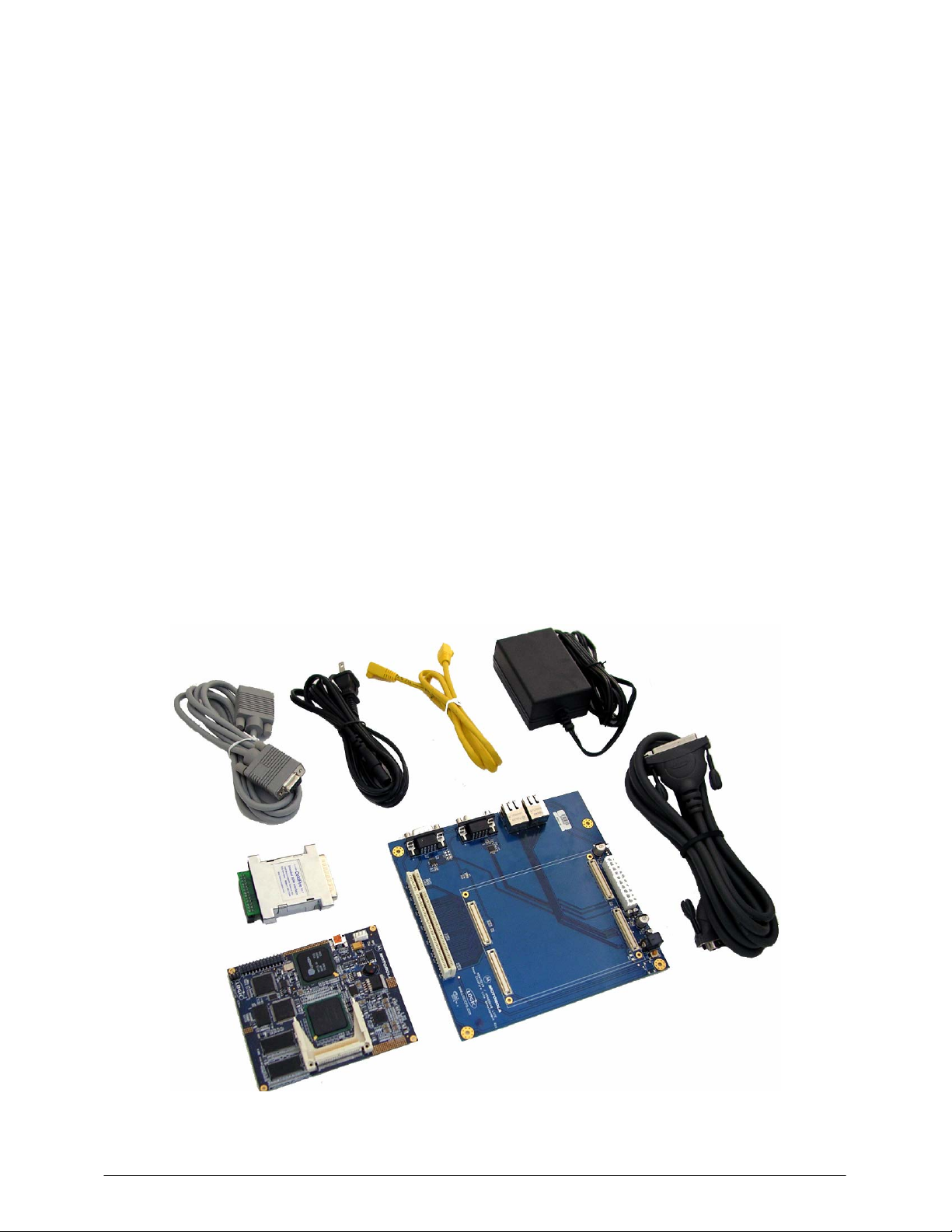
The Zoom ColdFire LITE Development Kit is comprised of the following items:
■ Mini-ITX LITE Baseboard
■ Fire Engine
■ CD ROM (See CD ROM Contents Section)
■ Serial Cable
■ BDM Interface
■ Ethernet crossover cable
■ Parallel extension cable
■ 5 volt power supply with power adapters (US, UK, EUR, and Japan)
■ Warranty Card
■ QuickStart Guide
■ Packing List
■ Third party development tools and software wrapped in individual CDs
Note: Avoid touching the MOS devices. Static discharge can and will damage these devices.
Once you have verified that all the items are present, remove the board from its protective jacket
and anti-static bag. Check the board for any visible damage and ensure that there are no broken,
damaged, or missing parts.
Figure 2.1 – Kit Contents
2
Zoom ColdFire QuickStart Guide
Page 6

2.2 CD-ROM Contents
Product Documentation
Fire Engine and Zoom ColdFire LITE Development Kit product briefs
Bill of Materials (.pdf format) for Fire Engine and Mini-ITX LITE Baseboard
Schematics (.pdf format) for Fire Engine and Mini-ITX LITE Baseboard
MCF547x/MCF548x Fire Engine Hardware Specification
MCF547x/MCF548x Fire Engine CPLD Specification, see section 11
Zoom ColdFire LITE User’s Manual
Fire Engine Design Guideline Application Note
Zoom ColdFire LITE Development Kit QuickStart Guide
LogicLoader User’s Manual
Software Development Tools
Tera-Term serial emulation program
Cygwin and GNU Cross Development Toolchain
Sample applications
References, Resources, and Support
Freescale Technical Information Center (TIC) www.freescale.com
Logic FAQ, Technical Discussion Group
Support Packages
Product Registration & Downloads
2.3 Development PC Requirements
General
Pentium processor or equivalent
64 MB RAM minimum
1 Gigabyte free hard disk space
115200 baud capable RS-232 port (COM port)
Tera Term serial emulation program (or equivalent)
Zoom ColdFire Lite QuickStart Guide
3
Page 7
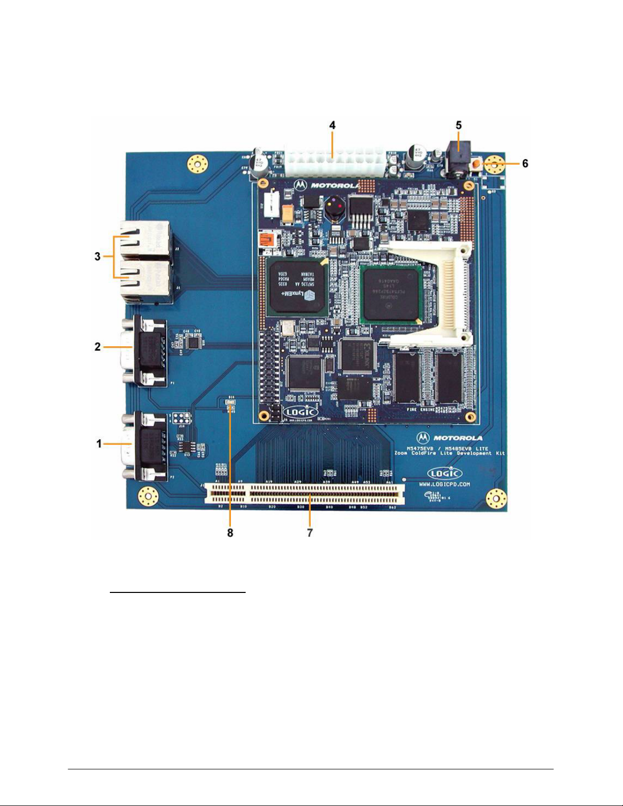
2.4 Mini ITX Lite Baseboard Connection Diagram
4
Figure 2.2 – Connection Diagram for the ITX Baseboard
Connection Diagram Details
1. CAN Port
2. Serial Port
3. Ethernet Ports
• Ethernet Port 1 (top in this image)
• Ethernet Port 0 (bottom in this image)
4. ATX Power Connector
5. 5V Power In -- use appropriate power adaptor
6. System Reset Button
7. PCI Connector
8. Power On LED
:
Important Note: The ITX baseboard is a common assembly board for all ColdFire LITE Development Kits and may
contain peripheral connectors that are not supported by the Fire Engine purchased.
Zoom ColdFire QuickStart Guide
Page 8

2.5 P&E Shielded BDM Interface Connection Diagram
Please ensure that your P&E Shielded BDM Interface is properly connected.
Figure 2.3 – P&E Shielded BDM Interface Properly Connected to the Fire Engine
Zoom ColdFire Lite QuickStart Guide
5
Page 9

3 QuickStart
3.1 Inserting the Fire Engine into the Mini-ITX Lite Baseboard
Insert the Fire Engine into the Hirose connectors on the Mini-ITX Lite Baseboard.
1) Position the Fire Engine’s four white 100 pin Hirose connectors directly above the four mating
Hirose connectors on the ITX Baseboard (see picture below).
2) Firmly press the Fire Engine downward on each connector until it is fully seated.
3) Verify that the Hirose connectors on the Fire Engine and Mini-ITX Baseboard have mated
correctly. To remove the Fire Engine, carefully pull upwards on any chosen corner of the Fire
Engine until one of the Hirose connectors on the baseboard releases. Repeat this motion
until all four Hirose connectors are no longer mated to the ITX Baseboard and remove.
Figure 3.1 – Inserting the Fire Engine into the Mini- ITX Lite Baseboard
6
Zoom ColdFire QuickStart Guide
Page 10

3.2 Connecting the Mini-ITX Lite Baseboard to your PC
Figure 3.2 – Connecting the Mini ITX Lite Baseboard to your PC
1. Connect the null-modem serial cable (supplied in the kit) to the serial port connector on the
baseboard and to a COM port on the Host PC.
2. Connect the regulated 5V power supply to the appropriate power adapter. Plug the power
adapter into the power outlet and the 5V line output connector into the power connector on the
baseboard.
3.3 Power Supply
The Fire Engine is equipped with 2 options for providing power:
■ 2.1 mm barrel connector with a positive center tap
■ Standard ATX power supply receptacle
Note: Do not connect more than one power supply at a time. The use of some PCI expansion
cards may require a separate ATX power supply due to power requirements of the card. See
Mini-ITX Lite Hardware Specification for power supply rating
Zoom ColdFire Lite QuickStart Guide
7
Page 11

4 Test Drive the Zoom ColdFire LITE Development Kit
4.1 Terminal Emulation Installation
The Zoom ColdFire LITE Developer Kit is designed to communicate with terminal emulation
programs via the null-modem serial cable included, using the following settings: 19200 baud, 8data-bits, 1-stop-bit, no-parity, and no-flow-control. The terminal emulation program must support
binary transfers in order to download software to the kit.
Although Logic Product Development does not support any particular terminal emulation
program, we suggest using Tera Term Pro for Windows 2000 or Windows XP. Tera Term Pro is
provided on the CD-ROM or can be downloaded for free from Logic’s website at the following
location: https://www.logicpd.com/auth/login.php
Logic Product Development does not guarantee or support any terminal emulation programs
under Linux or Windows platforms.
Once the terminal emulation program has been installed, open a new serial port connection using
the port where the null-modem serial cable is connected. For example, using Tera Term, set the
‘baud-rate’ to 19200, ‘data’ to 8-bit, ‘stop’ to 1-bit ,‘parity’ to none, and ‘flow control’ to none.
Figure 4.1 - Tera Term: Serial port setup window
. Tera Term Pro is not available for Linux users.
4.2 Power-up the Development Kit
The Zoom ColdFire LITE Development Kit will ship with both the Freescale and Logic
bootloader(s) installed in resident Flash. The Freescale ‘dBUG’ ROM monitor is the default
bootloader. LogicLoader can be accessed via dBUG ROM monitor, see section 4.2.2.
LogicLoader provides the capability for loading operating systems and applications. In addition, it
provides a full suite of commands for interfacing to the Fire Engine. These commands: load
operating systems, configure hardware platforms, bring-up hardware, customize applications,
perform tests, and manage in-field devices.
8
Zoom ColdFire QuickStart Guide
Page 12

4.2.1 dBUG ROM Monitor Power-up
When you start up your ColdFire LITE Development Kit in Tera Term, the dBUG ROM Monitor
will appear. The dBUG ROM Monitor is programmed into the Fire Engine’s boot Flash device.
Accessing dBUG
Interface to dBUG via a terminal emulation program connected via a null-modem serial cable to
the “Terminal” port of Fire Engine (Serial Port 0, top on the baseboard). Use the following default
terminal settings: 19200 baud, 8-data-bits, 1-stop-bit, no-parity, and no-flow-control.
1 Start a terminal program on the host computer (i.e. Tera Term, HyperTerminal, etc.).
2 Connect a serial cable to the host computer and to the Serial Port on the CDK.
3 Apply power to the Fire Engine.
4 In the terminal program you should now see a dBUG screen presenting text similar to this:
External Reset
ColdFire MCF548X on the M5485EVB
Firmware v3b.1a.1a (Built on Jul 13 2004 13:22:36)
Copyright 1995-2004 Freescale Semiconductor, Inc.
Check ColdFire website for dBUG updates
Enter 'help' for help.
dBUG>
Note: If the dBUG Monitor screen does not appear, please check Tera Term serial settings, all
cable connections, board connections, and press system reset.
5 Logic recommends that you immediately increase the baud rate for faster downloads and for
ease of interfacing to LogicLoader. To do so, enter the command ‘set baud 115200’ at the
dBUG prompt. Next, adjust the baud rate on your terminal emulation program to 115200.
Then press System Reset and you should see the startup screen that you saw in step 4.
Since the dBUG monitor program stores its settings in flash, the higher baud rate setting will
remain in effect until the next time it is changed.
4.2.2 LogicLoader (bootloader/monitor) Power-up
The Fire Engine is shipped with a version of the LogicLoader (bootloader/monitor) programmed
into the Boot Flash device at an offset of 0x40000.
Accessing LogicLoader
Interface to LogicLoader via a terminal emulation program connected via a null-modem serial
cable to the “Terminal” port of Fire Engine (Serial Port on the CDK). If you did not change the
baud rate, as suggested in step 5 of the previous section, use the following default terminal
settings: 19200 baud, 8-data-bits, 1-stop-bit, no-parity, and no-flow-control.
1 Start a terminal program on the host computer (i.e. Tera Term, HyperTerminal, etc.).
2 Connect a serial cable to the host computer and to the Serial Port on the CDK.
3 Apply power to the Fire Engine. By default dBUG will appear.
4 If you have not already done so, change the baud rate of dBUG to 115200 by following
the steps outlined in Section 4.2.1, Step 5 (above).
5 At the dBUG prompt enter the command ‘go ff840000’. Press Enter.
Zoom ColdFire Lite QuickStart Guide
9
Page 13

6 In the terminal program you should now see a LogicLoader screen presenting text similar to
the one below. Please refer to Section 11 for important information about the CPLD code.
dBUG> go ff840000
spi not initialized: cpld code not detected.
serial eeprom not initialized: cpld code not detected.
CPLD not programmed.
video-set-default: unable to open '/dev/serial_eeprom'
no default screen
*****************************************************************
LogicLoader
(c) Copyright 2002-2004, Logic Product Development, Inc.
All Rights Reserved.
Version 1.5.2-MCF5475_10 0001
*****************************************************************
Type 'help all' for a list of commands.
losh>
4.3 Using the Development Kit with the P&E ColdFire LITE BDM Interface
The Zoom ColdFire LITE Development Kit includes a ColdFire LITE BDM Interface from P&E
Microcomputer Systems that can be used with a variety of development tools. The installation
and use of the cable may vary between different development tool vendors.
In order to use the BDM with a particular toolset, please refer to readme files included with each
vendor’s development tools for specific instructions.
The BDM Interface should be plugged into the ETX board connector J10 (see Figure 2.3). Use
the included parallel cable included to connect the BDM to your PC’s parallel port. Refer to the
Pemicro website https://www.pemicro.com
use with your PC.
4.3.1 Using the BDM with the GNU Cross Development Toolchain
In order to use the BDM with the GNU cross development toolchain provided by Logic, jumper J1
must be moved to position 1-2 (Labeled ‘No’ in the silkscreen) on the BDM.
for the latest information on configuring the BDM for
10
Zoom ColdFire QuickStart Guide
Page 14

1. You must remove the BDM enclosure to change the jumper as shown below.
Figure 4.2 – Remove BDM Enclosure to change the Jumper
2. Next, configure your jumper as presented in the figure below.
Figure 4.3 – Jumper Setting for GNU Cross Development Toolchain
Zoom ColdFire Lite QuickStart Guide
11
Page 15

Connecting with the GDB Debugger
Please follow the steps below to connect your board with the GDB debugger.
1 Install Cygwin and the GNU Cross Development Tool Chain provided on the CD-ROM or
downloaded for free from Logic’s website at the following location:
https://www.logicpd.com/auth/login.php
2 Connect the BDM Interface to the ETX board connector J10 and a parallel cable to PC.
3 Open a Cygwin window and at the Cygwin prompt, then launch GDB by typing:
‘m68k-bdm-elf-gdb’ <enter>.
4 Connect GDB to the BDM Interface by typing ‘target bdm /dev/bdmcf0’ <enter>.
5 If you see the text ‘error: could not access the GiveIO device,’ you must manually start the
GIVEIO driver to give hardware access to GDB.
a. To manually start GIVEIO in Windows 2000, go to Device Manager and show
hidden devices by selecting View>Show Hidden Devices. Expand the Non-Plug
and Play Drivers category and double click on GIVEIO. Click the drivers tab. In
the ‘Current Status’ section, click ‘Start’. In the ‘Startup’ section, select
‘Automatic’. Click OK. Retry step 2 above.
6 Test the connection by typing ‘frame 0’ <enter>, ‘info reg’ <enter> to display system registers.
If you see the list of system registers, you are successfully connected.
4.4 Sample Application
The Zoom CDK LITE comes with a sample application that can be found on the website. For
instructions, see the Zoom CDK LITE User’s Manual.
.
12
Zoom ColdFire QuickStart Guide
Page 16

5 Jumper/Switch Table
The following table describes the function of the jumpers on the Fire Engine.
Table 5.1: Jumper Switch Table
Jumper Settings Function
J14 Jmp 2-4
Jmp 4-6
J14 Jmp 1-3
Jmp 3-5
CAN Port 1 Non-terminated
data line
CAN Port 1 Terminated data
line
CAN Port 1 Non-terminated
data line
CAN Port 1 Terminated data
line
Zoom ColdFire Lite QuickStart Guide
13
Page 17

6 Product Notices
The Zoom ColdFire LITE Development Kit being sold by Logic is intended for ENGINEERING
DEVELOPMENT OR EVALUATION PURPOSES ONLY. As such, the goods being provided may
not be complete in terms of required design, marketing, and/or manufacturing related protective
considerations, including product safety measures typically found in the end product incorporating
the goods. The user assumes all responsibility and liability for proper and safe handling of the
Zoom ColdFire LITE Development Kit.
ESD
Due to the open construction of the product, it is the user’s responsibility to take any and all
appropriate precautions with regard to electrostatic discharge. The various debug header pins are
tied to actual lines on the Fire Engine and ITX baseboard. Some of them will reset the board if
they are touched directly. Be aware of this situation. Logic’s warranty does not cover product
damaged by ESD.
Approvals
This product is compliant with emissions standard EN55022 level A, and may be operated in
industrial areas as defined by national regulations. This product may require a special permit for
operation at other locations. Cases of interference at such locations need to be handled
according to the requirements of the national EMC legislation
7 Product Registration
In order to access the latest revision of this manual, product change notifications, application
notes, schematics, and hardware specifications, please register your product online with a recent
version of Internet Explorer or Netscape.
In addition, you will be notified when Logic releases updates to your product.
Go to the Log In section on the Logic website at http://www.logicpd.com/support/
user account. You will receive an e-mail with your new username and password and additional
instructions. At this point, log in and complete the product registration form to gain access to
product download files.
, and create a
14
Zoom ColdFire QuickStart Guide
Page 18

8 Ordering Information
Zoom ColdFire LITE Development Kits, Fire Engines, and Display Kits are available direct from
Freescale or their worldwide distributors.
8.1 Zoom ColdFire LITE Development Kits
M5474EVB includes M5475CFE Fire Engine
M5484EVB includes M5485CFE Fire Engine
8.2 Fire Engine Configurations
DDR
Freescale PN
Mem
MCF5475AFE 64 0 Y - -
MCF5475BFE 64 16 Y - -
MCF5475CFE** 64 16 Y Y Y
MCF5475DFE 64 0 Y - Y
MCF5475EFE 64 0 Y Y Y
MCF5475FFE 128 32 Y Y Y
* When ordering Fire Engines with USB Host PCI slot is locked at 33 MHz
** Denotes the Fire Engine Configuration on M5475EVB Zoom ColdFire LITE Development
Kit
DDR
Freescale PN
Mem
MCF5485AFE 64 0 Y - -
MCF5485BFE 64 16 Y - -
MCF5485CFE** 64 16 Y Y Y
MCF5485DFE 64 0 Y - Y
MCF5485EFE 64 0 Y Y Y
MCF5485FFE 128 32 Y Y Y
* When ordering Fire Engines with USB Host PCI slot is locked at 25 MHz
** Denotes the Fire Engine Configuration on M5485EVB Zoom ColdFire LITE Development
Kit
Nor
Flash
Nor
Flash
Boot
Flash
Boot
Flash
Graphics
Ctrlr
Graphics
Ctrlr
USB
*
USB
*
8.3 Zoom ColdFire LITE Display Kits
See section 10.
Zoom ColdFire Lite QuickStart Guide
15
Page 19

9 Support
The Zoom ColdFire LITE Development Kit is a Freescale part number. Technical support should
be handled as follows:
1. First, contact your local Freescale sales office if there are any issues or questions.
2. Second, use Freescale’s Technical Information Center. See enclosed information card in box.
http:// freescale.com/semiconductors
3. Third, Logic has created an FAQ and Technical Discussion Group section on the Logic
website to make it easier for our customers to find answers to their questions. For additional
technical support, please see support packages below.
What support comes with the Zoom ColdFire LITE Development Kit?
Freescale local FAEs and online support forum at www.freescale.com
Unlimited access to Logic’s technical discussion group and FAQ’s available at
http://www.logicpd.com/support/
What is supported in the ColdFire LITE Development Kit?
Zoom ColdFire LITE Development Kit hardware
LogicLoader (Bootloader/Monitor)
What does Logic Product Development NOT support?
See respective third party solutions for technical support.
Freescale’s dBUG ROM Monitor
GNU cross development toolchain (http://www.gnu.org/)
Tera Term
Cygwin (http://www.cygwin.com/)
IC Components (contact appropriate IC vendor)
Additional Support Services Available for Purchase
Product Development Services
Industrial Design
Mechanical Engineering
Electrical Engineering
Systems & Software Engineering
PCB Design & Layout
FPGA/DSP Design
Support Packages
Visit http://www.logicpd.com/support/
Gold Support Package
Silver Support Package
Bronze Support Package
Hotline Incident
for complete descriptions, price, and purchase.
9.1 Frequently Asked Questions
Visit http://www.logicpd.com/support/ for a complete list of FAQ’s for the Zoom ColdFire LITE
Development Kit.
9.2 Technical Discussion Group
Visit http://www.logicpd.com/support/ to join our technical discussion group and share valuable
information with other designers.
16
Zoom ColdFire QuickStart Guide
Page 20

10 Zoom Display Kits
Display Kits are ideal for embedded solutions requiring a graphical user interface. Logic offers a
variety of display sizes (3.5”, 6.4”, 12.1”), resolutions (QVGA, VGA, SVGA), and types (TFT, etc.).
Zoom Display Kits are sold separately.
Visit Logic’s website at http://www.logicpd.com for a complete listing of Display Kits and
accessories for the ColdFire LITE Development Kits.
Figure 10.1 – Zoom Display Kit plugged into a Zoom ColdFire LITE Development Kit
10.1 Zoom Display Kits Specification Table
Logic offers the following Display Kits for use with the Application Development Kits. Visit our
website for current information on Zoom Display Kits.
Figure 10.2– Zoom Display Kits Specification Table
Logic Model Sharp LCD P/N
MQVGADK LQ035Q7DB02 3.5 in.
MVGADK LQ64D343 6.4 in.
MSVGADK LQ121S1DG41 12.1 in.
Important Notice: Please verify the selected processor supports the display kits.
Please contact Logic for other display requirements.
Zoom ColdFire Lite QuickStart Guide
Display Size
Diagonal
Display
Format
(240x320)
(640x480)
(800x600)
QVGA
VGA
SVGA
Type Key Features
Color TFT
Color TFT
Color TFT
Color,
transreflective
Color,
transmissive
Color,
transmissive
17
Page 21

11 Fire Engine CPLD Important Notice
The CPLD device on the Fire Engine included in the M547xEVB and M548xEVB development
kits does not contain any CPLD code.
The CPLD is not required to run the microprocessor memory architecture or on-chip peripherals.
Logic has developed additional features in the CPLD that provide the following interfaces and
functionality:
1 ISA-Like bus interface
2 Serial EEPROM interface
This interface can be used for scripting. Scripting is a method to execute losh commands
automatically by listing them in a script file and using the command "source" to run the script
in the file. This is useful for automating repetitive command line entries. For example: the
command "source /cf_card/MYSCRIPT.TXT" will execute the script stored in the file
"myscript.txt" on a mounted CompactFlash card.
3 CompactFlash Type 1 memory mode only interface
The LogicLoader contains support for booting from the CompactFlash interface on the Fire
Engine. This command makes that interface available to other commands through the file
system. If an ELF, BIN, RAW, or S-record image is stored on the CompactFlash card, that
image may be loaded into memory.
4 Board Power Management features
These interfaces are supported in LogicLoader (bootloader/monitor). For more information on
LogicLoader, please see User’s manual on CD-ROM. Other operating systems will need to
develop drivers to support the interfaces.
The CPLD code is available free of charge for customers designing the Fire Engine into their final
product or for purchase if implementing in a custom board solution. For more information on
purchasing or licensing the CPLD VHDL code, please contact Logic sales at
product.sales@logicpd.com and request a license agreement.
Fire Engines are available with CPLD code pre-loaded and can be ordered from Freescale using
the following part number M547xxFE and M548xxFE, where ‘xx’ denotes configuration. See Fire
Engine product brief for a complete list of configurations.
18
Zoom ColdFire QuickStart Guide
Page 22

12 Troubleshooting
Q: My board does not respond with BDM interface connected, what can I do?
A: Try pressing the System Reset button (see Figure 2.2).
Q: My CompactFlash connector does not work, why?
A: See Section 11 regarding CompactFlash functionality.
Q: How do I use CPLD devices on the board?
A: See Section 11 for a list of functionality and options for obtaining CPLD code.
13 Warranty Statement
Refer to warranty card enclosed in development kit.
Zoom ColdFire Lite QuickStart Guide
19
 Loading...