

Freescale Semiconductor, Inc.
© Freescale Semiconductor, Inc., 2013. All rights reserved.
Document Number: KTUSBSPIEVMEUG
User’s Guide
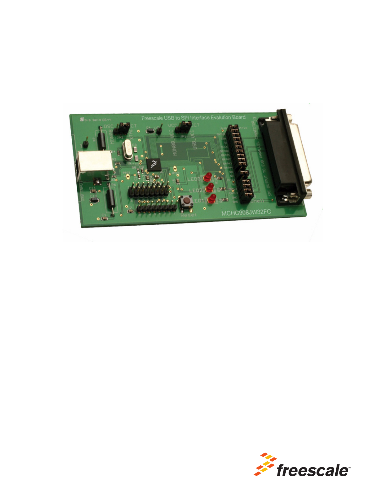
KITUSBSPIEVME USB-to-SPI Interface Board
Featuring the MC68HC908JW32
Rev. 4.0, 4/2013
Figure 1. KITUSBSPIEVME Board
Table of Contents
1 Kit Contents/Packing List . . . . . . . . . . . . . . . . . . . . . . . . . . . . . . . . . . . . . . . . . . . . . . . . . . . . . . . . . . . 2
2 Jump Start. . . . . . . . . . . . . . . . . . . . . . . . . . . . . . . . . . . . . . . . . . . . . . . . . . . . . . . . . . . . . . . . . . . . . . . 2
3 Important Notice . . . . . . . . . . . . . . . . . . . . . . . . . . . . . . . . . . . . . . . . . . . . . . . . . . . . . . . . . . . . . . . . . . 3
4 Introduction . . . . . . . . . . . . . . . . . . . . . . . . . . . . . . . . . . . . . . . . . . . . . . . . . . . . . . . . . . . . . . . . . . . . . . 4
6 Board Layout. . . . . . . . . . . . . . . . . . . . . . . . . . . . . . . . . . . . . . . . . . . . . . . . . . . . . . . . . . . . . . . . . . . . . 6
7 Bill of Material . . . . . . . . . . . . . . . . . . . . . . . . . . . . . . . . . . . . . . . . . . . . . . . . . . . . . . . . . . . . . . . . . . . . 8
8 References . . . . . . . . . . . . . . . . . . . . . . . . . . . . . . . . . . . . . . . . . . . . . . . . . . . . . . . . . . . . . . . . . . . . . 10
9 Revision History . . . . . . . . . . . . . . . . . . . . . . . . . . . . . . . . . . . . . . . . . . . . . . . . . . . . . . . . . . . . . . . . . 11
Kit Contents/Packing List
Jump Start Your Design
1 Kit Contents/Packing List
•Assembled and tested interface board/module in anti-static bag.
•Six-foot USB 2.0 A-M to B-M cable
•Warranty card
2Jump Start
•Go to www.freescale.com/analogtools
• Locate your kit
• Review your Tool Summary Page
• Look for
• Download documents, software and other information
KTUSBSPIEVMEUG User’s Guide Rev. 4.0 4/2013
2 Freescale Semiconductor

3 Important Notice
Freescale provides the enclosed product(s) under the following conditions:
This evaluation kit is intended for use of ENGINEERING DEVELOPMENT OR EVALUATION PURPOSES ONLY. It
is provided as a sample IC pre-soldered to a printed circuit board to make it easier to access inputs, outputs, and
supply terminals. This EVB may be used with any development system or other source of I/O signals by simply
connecting it to the host MCU or computer board via off-the-shelf cables. This EVB is not a Reference Design and is
not intended to represent a final design recommendation for any particular application. Final device in an application
will be heavily dependent on proper printed circuit board layout and heat sinking design as well as attention to supply
filtering, transient suppression, and I/O signal quality.
The goods provided may not be complete in terms of required design, marketing, and or manufacturing related
protective considerations, including product safety measures typically found in the end product incorporating the
goods. Due to the open construction of the product, it is the user's responsibility to take any and all appropriate
precautions with regard to electrostatic discharge. In order to minimize risks associated with the customers
applications, adequate design and operating safeguards must be provided by the customer to minimize inherent or
procedural hazards. For any safety concerns, contact Freescale sales and technical support services.
Should this evaluation kit not meet the specifications indicated in the kit, it may be returned within 30 days from the
date of delivery and will be replaced by a new kit.
Freescale reserves the right to make changes without further notice to any products herein. Freescale makes no
warranty, representation or guarantee regarding the suitability of its products for any particular purpose, nor does
Freescale assume any liability arising out of the application or use of any product or circuit, and specifically disclaims
any and all liability, including without limitation consequential or incidental damages. “Typical” parameters can and
do vary in different applications and actual performance may vary over time. All operating parameters, including
“Typical”, must be validated for each customer application by customer’s technical experts.
Freescale does not convey any license under its patent rights nor the rights of others. Freescale products are not
designed, intended, or authorized for use as components in systems intended for surgical implant into the body, or
other applications intended to support or sustain life, or for any other application in which the failure of the Freescale
product could create a situation where personal injury or death may occur.
Should the Buyer purchase or use Freescale products for any such unintended or unauthorized application, the Buyer
shall indemnify and hold Freescale and its officers, employees, subsidiaries, affiliates, and distributors harmless
against all claims, costs, damages, and expenses, and reasonable attorney fees arising out of, directly or indirectly,
any claim of personal injury or death associated with such unintended or unauthorized use, even if such claim alleges
that Freescale was negligent regarding the design or manufacture of the part.Freescale™ and the Freescale logo
are trademarks of Freescale Semiconductor, Inc. All other product or service names are the property of their
respective owners.
© Freescale Semiconductor, Inc. 2013
Important Notice
KTUSBSPIEVMEUG User’s Guide Rev. 4.0 4/2013
Freescale Semiconductor 3
Introduction
4 Introduction
The KITUSBSPIEVME board converts from USB to SPI and from USB to parallel data transmission. The
main function provided by this board is to allow a PC that may not have a parallel port to communicate
with other Freescale evaluation boards via a USB port.
.
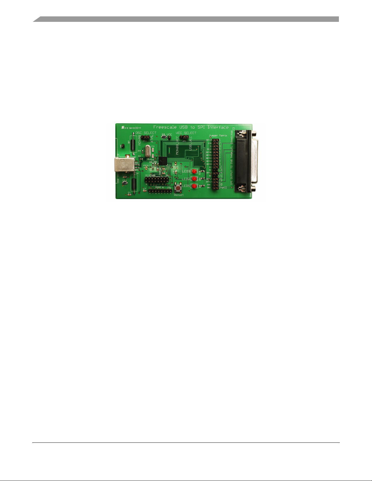
Figure 1. KITUSBSPIEVME Converter Board
Freescale analog ICs are manufactured using the SMAR
manufacturing flow that integrates precision analog, power functions and dense CMOS logic together on
a single cost-effective die.
TMOS process, a combinational BiCMOS
KTUSBSPIEVMEUG User’s Guide Rev. 4.0 4/2013
4 Freescale Semiconductor

5 Schematic
Z
Z
USB_VCC
+5V
D-
D+
GND
1
2
3
4
USB
Ferrite
Ferrite
C1
.1μF
27
27
R1
R2
R3
1.5K
D-
D+
30
31
32
REG33V
MON08
J4
1
16
JP2
Oscillator
Select
12 3
2526
OSC1
OSC2
10M
XTAL-1
27 pF
27 pF
C2
C3
2
PTC1
PTA1
PTA0
2
4
6
8
1012141816
20
22
2426283032
34
1
1
JUMPER
MATRIX
25 PIN D-SUB
CONNECTOR
3
352
7
9
111315
17
19
21
23
25
456
7
8
9
12
13
14
20
31
33
15
16
17
CNTL0
CSB
SI
SCLK
DATA0
DATA1
DATA2
DATA3
DATA4
SO
CNTL1
CNTL2
CNTL3
GND
27
29
11
PTE4/SPCLK
10
PTE5/MOSI
9
PTE6/MISO
17
PTD4
161514
13
PTD0
PTD1
PTD2
PTD3
8
PTE7/SSB
18
PTD5
PTD6
19
22
PTD7
7
PTC0/1CH0
123
JP1
VCC
Select
VCC
447481
RST
37
IRQB
38
C7
.1μF
RESET
PUSBUTTON
4 mHz
LED2
LED1
LED3
VCC
VCC
VCC
R9
470
470
470
R10
R8
PTB56PTB1
28
PTB0
27
29
VSS
VSSPLL
33
VSS33VDDPLL
35 44
VDD
VCC
.1μF
C6
C13
.1μF
C12 C11
+
10 μF
10 V
.1μF
42
C9
2.2 nF
C8
100 pF
R5
2.2K
CGMXFC
34
U1
PORT A
J2
PTA7
36
PTA6
PTA5
PTA4
PTA3
PTA2
39404546
PTA2
PTA1
PTA0
RST
IRQB
MON08_VCC
PTC3
5
J10
PTC3
PTC2 PTC2
41
VCC Select and Oscillator Select Jumpers
shown in the Operate Position
VCC Select
Jumper 1-2 = Operate Position
Jumper 2-3 = Programming Position
Oscillator Select
Jumper 1-2 = Operate Position
Jumper 2-3 = Programming Position
.1μF
C5
REG25V
43
C10
.1μF
Schematic
KTUSBSPIEVMEUG User’s Guide Rev. 4.0 4/2013
Freescale Semiconductor 5

Board Layout
6 Board Layout
6.1 Top Layer Routing
KTUSBSPIEVMEUG User’s Guide Rev. 4.0 4/2013
6 Freescale Semiconductor

6.2 Bottom Layer Routing
Board Layout
KTUSBSPIEVMEUG User’s Guide Rev. 4.0 4/2013
Freescale Semiconductor 7

Bill of Material
7 Bill of Material
Schematic
Label
Device/
Signal
Name
Value/Description Manufacturer Part Number Package
Capacitors
C1 USB_VCC CAP CER 0.1 μF 50 V 20% Z5U CC1206
C2
C3
C4
C5
C6 VCC CAP CER 0.1 μF 50 V 20% Z5U CC1206
C7 VOSC CAP CER 0.1 μF 50 V 20% Z5U CC1206
C8 CGMXFC CAP CER 100 PF 50 V 10% COG 0603
C9 CGMXFC CAP CER 0.022 μF 25 V 10% X7R CC0603 CC1206
C10 REG2.5V CAP CER 0.1 μF 50 V 20% Z5U CC1206
C11 REG3.3V CAP CER 0.1 μF 50 V 20% Z5U CC1206
C12 REG3.3V CAP TANT 10 μF 10 V 10% -- CASE_A
C13 VDD_PLL CAP CER 0.1 μF 50 V 20% Z5U CC1206
C14 VR_OUT CAP TANT 10 μF 10 V 10% -- CASE_A
OSC2 CAP CER 27 PF 50 V 5% C0G CC1206 CC1206
OSC1 CAP CER 27 PF 50 V 5% C0G CC1206 CC1206
VBAT CAP CER 0.1 μF 50 V 20% Z5U CC1206
MON08_VCC CAP CER 0.1 μF 50 V 20% Z5U CC1206
ROHS COMPLIANT
ROHS COMPLIANT
ROHS COMPLIANT
ROHS COMPLIANT
ROHS COMPLIANT
ROHS
ROHS COMPLIANT
ROHS COMPLIANT
ROHS
ROHS COMPLIANT
ROHS
Resistors
R1 D- RES TF 27 1/10 W 1% RC0603 ROHS
R2 D+ RES TF 27 1/10 W 1% RC0603 ROHS
R3 D- RES TF 1.50 K 1/10 W 1% RC0603 ROHS
R4 OSC1 OSC2 RES TF 10 M 1/10 W 5% RC0603 ROHS
R5 CGMXFC RES TF 2.2 K 1/10 W 5% RC0603 ROHS
R6 USB_VCC JUMPER WIRE WITH FERRITE BEAD
R7 GND JUMPER WIRE WITH FERRITE BEAD
R8 LED1 PU RES TF 470 1/8 W 5% RC0805 ROHS
R9 LED2 PU RES TF 470 1/8 W 5% RC0805 ROHS
R10 LED3 PU RES TF 470 1/8 W 5% RC0805 ROHS
COMPLIANT
COMPLIANT
COMPLIANT
COMPLIANT
COMPLIANT
28L0138-40R-10
28L0138-40R-10
COMPLIANT
COMPLIANT
COMPLIANT
CC1206
CC1206
CC1206
CC1206
CC1206
CC1206
CC1206
CC1206
Case A
CC1206
Case A
RC0603
RC0603
RC0603
RC0603
RC0603
RC0805
RC0805
RC0805
KTUSBSPIEVMEUG User’s Guide Rev. 4.0 4/2013
8 Freescale Semiconductor

Bill of Material
Schematic
Label
Device/
Signal
Name
Value/Description Manufacturer Part Number Package
LEDs
LED1 LED LED 5 mm VERT LOW CUR RED PC MNT DIALIGHT 561-1101-060 PCB Vertical
5 mm
LED2 LED LED 5 mm VERT LOW CUR RED PC MNT DIALIGHT 561-1101-060 PCB Vertical
5 mm
LED3 LED LED 5 mm VERT LOW CUR RED PC MNT DIALIGHT 561-1101-060 PCB Vertical
5 mm
Integrated Circuits
U1 MICRO MC68HC908JW32 8 bit USB/SPI
microcontroller ROHS COMPLIANT
FREESCALE
SEMICONDUCTOR
MC68HC908JW32 QFN-48
Crystal Oscillators
XTAL-1 OSC1 OSC2 XTAL 4.0 MHZ RSN 50 PPM TH CL=10 PF
ROHS
FOX ELECTRONICS FOXSLF/040 HC49/S
Connectors, Jumpers and Switches
JP1 VCC
SELECT
JP2 OSC
SELECT
J1 USB USB B PC MOUNT FEMALE CONNECTOR
J2 PORT A 8 pin HDR 1X10 100 MIL CTR LOW
J3 PARALLEL
PORT
J4 MON08 16-pin HDR 2X8 100 MIL CTR LOW
J5 VCC 1 pin HDR 1X1 100 MIL CTR LOW
J6 JUMPER
MATRIX
J7 GND 1 pin HDR 1X1 100 MIL CTR LOW
J8 PORT D 8 pin HDR 1X9 100 MIL CTR LOW
J9 PTC2 1 pin HDR 1X1 100 MIL CTR LOW
J10 PTC3 1 pin HDR 1X1 100 MIL CTR LOW
SW1 RESET PB SW PB MOM SMT
Note: Freescale does not assume liability, endorse, or warrant components from external manufacturers that are referenced in circuit drawings
or tables. While Freescale offers component recommendations in this configuration, it is the customer’s responsibility to validate their application.
3 pin HDR 1X10 100 MIL CTR LOW
PROFILE BREAKAWAY ROHS
COMPLIANT
3 pin HDR 1X10 100 MIL CTR LOW
PROFILE BREAKAWAY ROHS
COMPLIANT
ROHS COMPLIANT
PROFILE BREAKAWAY ROHS
COMPLIANT
CON 25 DB RA SKT TH -- AU BRDLK
ROHS COMPLIANT
PROFILE BREAKAWAY ROHS
COMPLIANT
PROFILE BREAKAWAY ROHS
COMPLIANT
34 pin HDR 2X17 100 MIL CTR LOW
PROFILE BREAKAWAY ROHS
COMPLIANT
PROFILE BREAKAWAY ROHS
COMPLIANT
PROFILE BREAKAWAY ROHS
COMPLIANT
PROFILE BREAKAWAY ROHS
COMPLIANT
PROFILE BREAKAWAY ROHS
COMPLIANT
KTUSBSPIEVMEUG User’s Guide Rev. 4.0 4/2013
Freescale Semiconductor 9

References
8 References
Following are URLs where you can obtain information on other Freescale products and application
solutions:
Freescale.com
Support Pages
KITUSBSPIEVME
Tool Summary Page
SPIGen
Tool Summary Page
Analog Home Page http://www.freescale.com/analog
Automotive Home Page http://www.freescale.com/automotive
http://www.freescale.com/webapp/sps/site/prod_summary.jsp?code=KITUSBSPIEVME
http://www.freescale.com/files/soft_dev_tools/software/device_drivers/SPIGen.html
8.1 Support
Visit www.freescale.com/support for a list of phone numbers within your region.
8.2 Warranty
Visit www.freescale.com/warranty for a list of phone numbers within your region.
URL
KTUSBSPIEVMEUG User’s Guide Rev. 4.0 4/2013
10 Freescale Semiconductor

9 Revision History
Revision Date Description of Changes
1.0 2/2008 • Initial Release
2.0 12/2009 • Converted to new format
3.0 3/2010 • Updated to new format
4.0 4/2013 • Add Jump Start link for downloading software and/or documents
• Add Introduction including board photo
Revision History
KTUSBSPIEVMEUG User’s Guide Rev. 4.0 4/2013
Freescale Semiconductor 11

How to Reach Us:
Home Page:
freescale.com
Web Support:
freescale.com/support
Information in this document is provided solely to enable system and software implementers to use Freescale
products. There are no express or implied copyright licenses granted hereunder to design or fabricate any
integrated circuits based on the information in this document.
Freescale reserves the right to make changes without further notice to any products herein. Freescale makes no
warranty, representation, or guarantee regarding the suitability of its products for any particular purpose, nor does
Freescale assume any liability arising out of the application or use of any product or circuit, and specifically
disclaims any and all liability, including without limitation consequential or incidental damages. “Typical” parameters
that may be provided in Freescale data sheets and/or specifications can and do vary in different applications, and
actual performance may vary over time. All operating parameters, including “typicals,” must be validated for each
customer application by customer’s technical experts. Freescale does not convey any license under its patent rights
nor the rights of others. Freescale sells products pursuant to standard terms and conditions of sale, which can be
found at the following address: freescale.com/SalesTermsandConditions.
Freescale and the Freescale logo are trademarks of Freescale Semiconductor, Inc., Reg. U.S. Pat. & Tm. Off.
SMARTMOS is a trademark of Freescale Semiconductor, Inc. All other product or service names are the property
of their respective owners.
© 2013 Freescale Semiconductor, Inc.
Document Number: KTUSBSPIEVMEUG
Rev. 4.0
4/2013
 Loading...