

Freescale Semiconductor
Document Number: KTUSBSPIDGLUG
User’s Guide
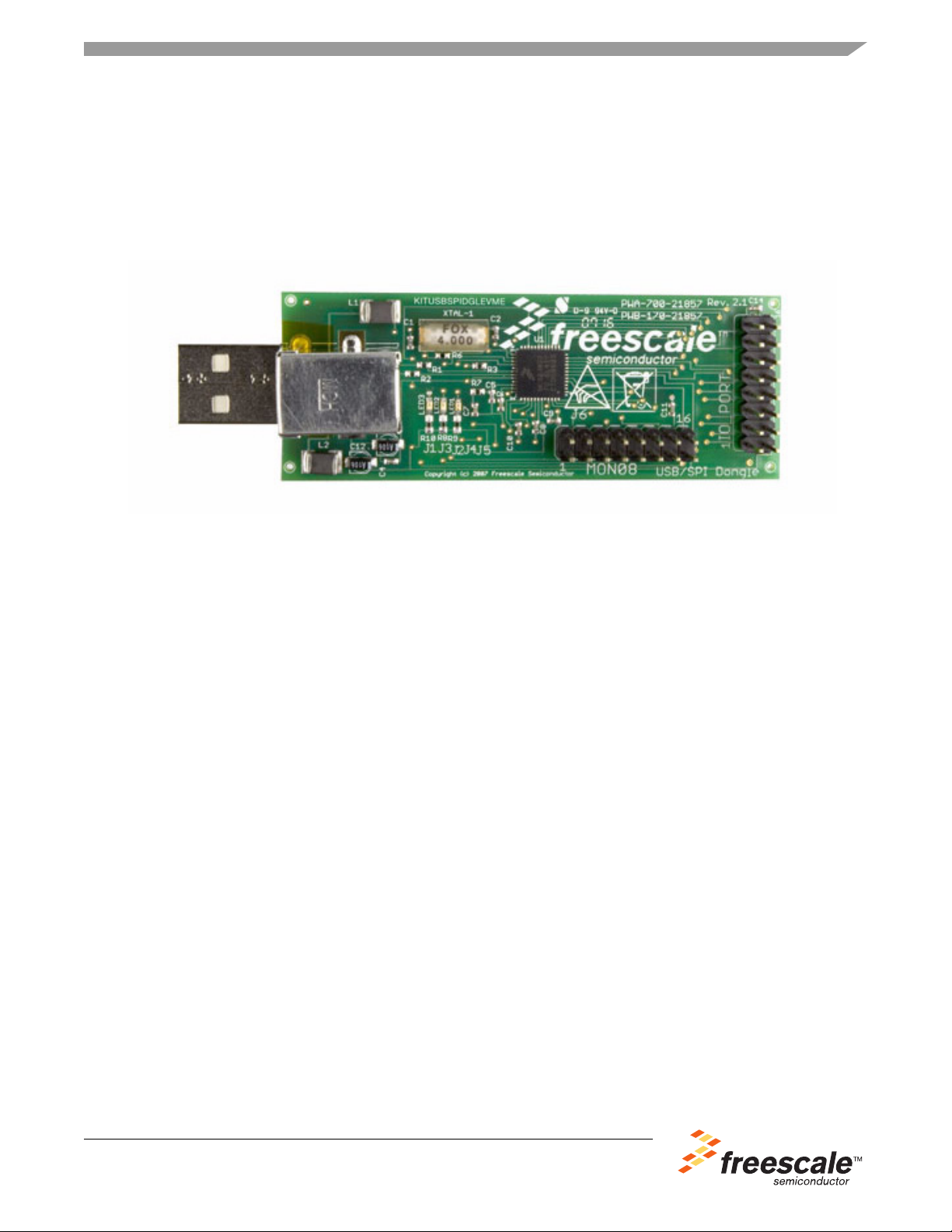
KITUSBSPIDGLEVME USB-to-SPI Interface Board
Featuring the MC68HC908JW32 with Dongle
Figure 1. KITUSBSPIDGLEVME Board
Rev. 2.0, 4/2013
Table of Contents
1 Kit Contents/Packing List . . . . . . . . . . . . . . . . . . . . . . . . . . . . . . . . . . . . . . . . . . . . . . . . . . . . . . . . . . . 2
2 Jump Start. . . . . . . . . . . . . . . . . . . . . . . . . . . . . . . . . . . . . . . . . . . . . . . . . . . . . . . . . . . . . . . . . . . . . . . 2
3 Important Notice . . . . . . . . . . . . . . . . . . . . . . . . . . . . . . . . . . . . . . . . . . . . . . . . . . . . . . . . . . . . . . . . . . 3
4 Introduction . . . . . . . . . . . . . . . . . . . . . . . . . . . . . . . . . . . . . . . . . . . . . . . . . . . . . . . . . . . . . . . . . . . . . . 4
5 Schematic . . . . . . . . . . . . . . . . . . . . . . . . . . . . . . . . . . . . . . . . . . . . . . . . . . . . . . . . . . . . . . . . . . . . . . . 5
6 Board Layout. . . . . . . . . . . . . . . . . . . . . . . . . . . . . . . . . . . . . . . . . . . . . . . . . . . . . . . . . . . . . . . . . . . . . 6
7 Bill of Material . . . . . . . . . . . . . . . . . . . . . . . . . . . . . . . . . . . . . . . . . . . . . . . . . . . . . . . . . . . . . . . . . . . . 7
8 References . . . . . . . . . . . . . . . . . . . . . . . . . . . . . . . . . . . . . . . . . . . . . . . . . . . . . . . . . . . . . . . . . . . . . . 9
9 Revision History . . . . . . . . . . . . . . . . . . . . . . . . . . . . . . . . . . . . . . . . . . . . . . . . . . . . . . . . . . . . . . . . . 10
© Freescale Semiconductor, Inc., 2013. All rights reserved.

Kit Contents/Packing List
Jump Start Your Design
Go to www.freescale.com/analogtools, select your product
and download installation software and documentation.
1 Kit Contents/Packing List
• Assembled and tested interface board/module in anti-static bag.
• Six-foot USB 2.0 A-M to B-M cable
• Six-inch 16-pin ribbon cabl
• Warranty card
e assy, 0.100" pitch
2Jump Start
Go to www.freescale.com/analogtools and select your kit.
KTUSBSPIDGLUG User’s Guide Rev. 2.0 4/2013
2 Freescale Semiconductor

3 Important Notice
Freescale provides the enclosed product(s) under the following conditions:
This evaluation kit is intended for use of ENGINEERING DEVELOPMENT OR EVALUATION PURPOSES ONLY. It
is provided as a sample IC pre-soldered to a printed circuit board to make it easier to access inputs, outputs, and
supply terminals. This EVB may be used with any development system or other source of I/O signals by simply
connecting it to the host MCU or computer board via off-the-shelf cables. This EVB is not a Reference Design and is
not intended to represent a final design recommendation for any particular application. Final device in an application
will be heavily dependent on proper printed circuit board layout and heat sinking design as well as attention to supply
filtering, transient suppression, and I/O signal quality.
The goods provided may not be complete in terms of required design, marketing, and or manufacturing related
protective considerations, including product safety measures typically found in the end product incorporating the
goods. Due to the open construction of the product, it is the user's responsibility to take any and all appropriate
precautions with regard to electrostatic discharge. In order to minimize risks associated with the customers
applications, adequate design and operating safeguards must be provided by the customer to minimize inherent or
procedural hazards. For any safety concerns, contact Freescale sales and technical support services.
Should this evaluation kit not meet the specifications indicated in the kit, it may be returned within 30 days from the
date of delivery and will be replaced by a new kit.
Freescale reserves the right to make changes without further notice to any products herein. Freescale makes no
warranty, representation or guarantee regarding the suitability of its products for any particular purpose, nor does
Freescale assume any liability arising out of the application or use of any product or circuit, and specifically disclaims
any and all liability, including without limitation consequential or incidental damages. “Typical” parameters can and
do vary in different applications and actual performance may vary over time. All operating parameters, including
“Typical”, must be validated for each customer application by customer’s technical experts.
Freescale does not convey any license under its patent rights nor the rights of others. Freescale products are not
designed, intended, or authorized for use as components in systems intended for surgical implant into the body, or
other applications intended to support or sustain life, or for any other application in which the failure of the Freescale
product could create a situation where personal injury or death may occur.
Should the Buyer purchase or use Freescale products for any such unintended or unauthorized application, the Buyer
shall indemnify and hold Freescale and its officers, employees, subsidiaries, affiliates, and distributors harmless
against all claims, costs, damages, and expenses, and reasonable attorney fees arising out of, directly or indirectly,
any claim of personal injury or death associated with such unintended or unauthorized use, even if such claim alleges
that Freescale was negligent regarding the design or manufacture of the part.Freescale™ and the Freescale logo
are trademarks of Freescale Semiconductor, Inc. All other product or service names are the property of their
respective owners.
© Freescale Semiconductor, Inc., 2013. All rights reserved.
Important Notice
KTUSBSPIDGLUG User’s Guide Rev. 2.0 4/2013
Freescale Semiconductor 3
Introduction
4 Introduction
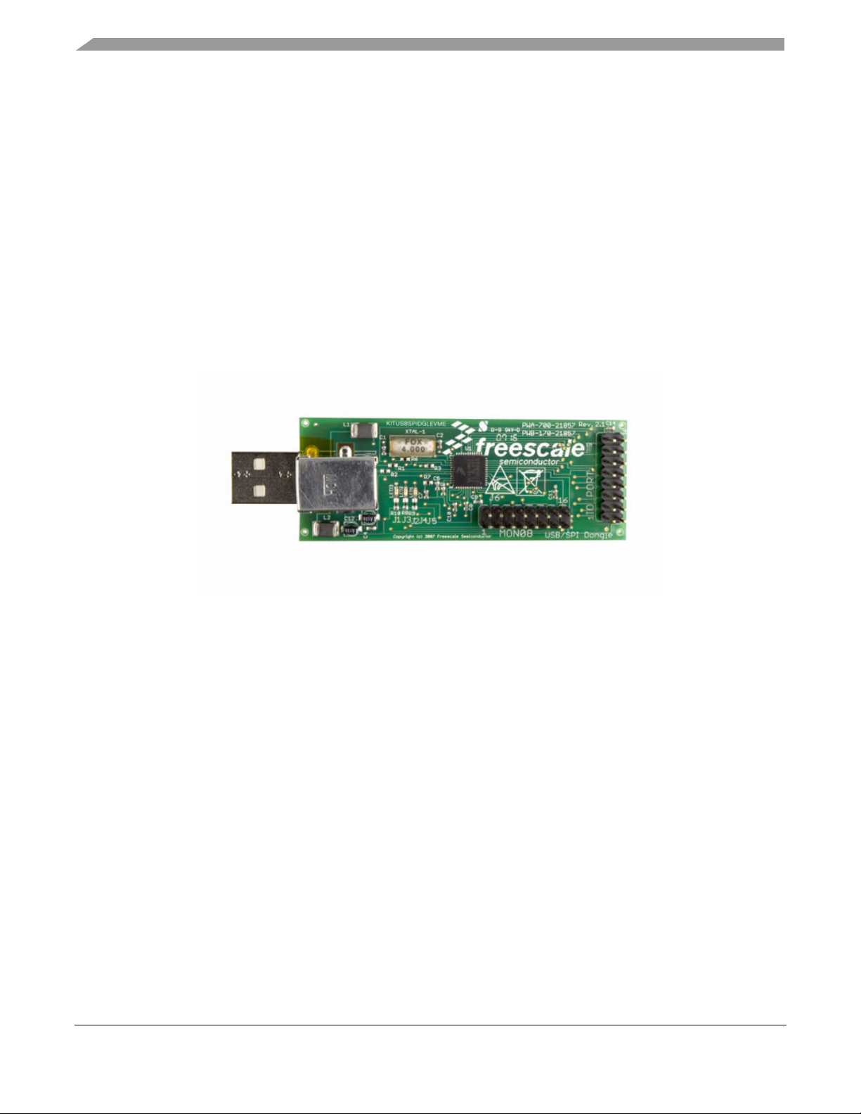
The KITUSBSPIDGLEVME interface board (shown below) provides a USB-to-SPI interface that features
the MC68HC908JW32 with Dongle. It is a working hardware/software example that allows a user to
become familiar with the MC68HC908JW32 microcontroller by means of an actual useful application, a
USB-to-SPI and USB-to-parallel converter. The main function provided by this kit is to allow a PC, that
may not have a parallel port, to communicate with other Freescale Evaluation Kits, via a USB port. The
USB port is a standard feature on almost every new PC. This kit makes use of the MC68HC908JW32’s
built-in USB, SPI and parallel ports.
Freescale analog ICs are manufactured using the SMARTMOS process, a combinational BiCMOS
manufacturing flow that integrates precision analog, power functions and dense CMOS logic together on
a single cost-effective die.
Figure 2. KITUSBSPIDGLEVME Interface Kit
KTUSBSPIDGLUG User’s Guide Rev. 2.0 4/2013
4 Freescale Semiconductor

5 Schematic
VDD VDD
VDD
VDD
MON08
IO PORT
USB INPUT
CNTL2
CNTL1
CNTL0
DATA4
DATA3
DATA2
DATA1
DATA0
CNTL3
CSBSOSI
SCLK
VDD
REG 3.3V
OSC1
PTA7
PTA6
PTA5
PTA4
PTC2
PTA3
PTC1
PTA2
PTA1
PTA0
PTC3
IRQB
RESETB
GND
VDD
GND
USB_TYPE_B_MALE
1
2
34
+D
-D
G
V
J1
CCUSBB-32004-00X
1
2
34
+D
-D
G
V
J1
CCUSBB-32004-00X
123
4
S1
S2
R8
470 OHMR8470 OHM
HC908JW32
U1
HC908JW32
HC908JW32
U1
HC908JW32
PTA2/KBA2
47
PTA3/KBA3
46
PTA4/KBA4
45
PTA5/KBA5
40
PTA6/KBA6
39
PTA7/KBA7
36
PTB027PTB1
28
PTC1/TCLK1
4
PTC2/T1CH1
41
PTC35PTD518PTD417PTD316PTD215PTD114PTD0
13
VDD
42
VSS
44
IRQ38RESET
37
PTD7
22
OSC125OSC2
26
PTA0/KBA0
1
PTA1/KBA1
48
PTC0/T1CH0
7
PTD6
19
VDDPLL
35
PTB5
6
CGMXFC
34
REG33V32REG25V
43
VSS33
29
PTE7/SS
8
PTE6/MISO9PTE5/MOSI
10
PTE4/SPCLK
11
PTE3/D-
31
PTE2/PS2CLK/D+
30
NC320NC421NC523NC6
24
NC02NC13NC2
12
VSSPLL
33
+
C12
10UF
+
C12
10UF
1 2
C7
2200PFC72200PF
12
R7
2.2KR72.2K
LED1
RED
LED1
RED
21
J6
0ohmJ60ohm
R1
27 OHMR127 OHM
C8
0.1uFC80.1uF
12
C1
22PFC122PF
12
C6
0.1uFC60.1uF
1 2
C2
22PFC222PF
12
XTAL-1
4MHz
XTAL-1
4MHz
1 2
J1
0ohmJ10ohm
J2
0ohmJ20ohm
C9
0.1uFC90.1uF
12
R6
10MR610M
R10
470 OHM
R10
470 OHM
+
C3
10UF+C3
10UF
12
J2
TSW-108-07-GD
J2
TSW-108-07-GD
12
34
6 5
78
910
1112
1314
1516
C10
0.1uF
C10
0.1uF
12
L2
100 ohmL2100 ohm
1 2
J3
0ohmJ30ohm
LED2
RED
LED2
RED
21
J4
0ohmJ40ohm
VD-D+G
J4
USB_TYPE_A_MALE
VD-D+G
J4
USB_TYPE_A_MALE
S1
A1
A2
A3
A4
S2
R2
27 OHMR227 OHM
L1
100 ohmL1100 ohm
1 2
C14
0.1uF
C14
0.1uF
12
R9
470 OHMR9470 OHM
J5
0ohmJ50ohm
C4
0.1uFC40.1uF
12
R3
1.5KR31.5K
LED3
RED
LED3
RED
21
J3
TSW-108-07-GD
J3
TSW-108-07-GD
1 2
3 4657 8
9 10
11 12
13 14
15 16
C5
100pFC5100pF
12
Schematic
Freescale Semiconductor 5
KTUSBSPIDGLUG User’s Guide Rev. 2.0 4/2013

Board Layout
6 Board Layout
6.1 Assembly Layer Top
6.2 Top Layer Routing
6.3 Bottom Layer Routing
KTUSBSPIDGLUG User’s Guide Rev. 2.0 4/2013
6 Freescale Semiconductor

7 Bill of Material
Bill of Material
Schematic
Label
Capacitors
C1 OSC2 CAP CER 22PF 50V 5% C0G CC0402
C2 OSC1 CAP CER 22PF 50V 5% C0G CC0402
C3 REG3.3V CAP TANT 10UF 10V 10%
C4 REG3.3V CAP CER 0.1UF 10V 20% Y5V 0402
C5 CGMXFC CAP CERAMIC 100PF 50V NP0 0402
C6 VDD PLL CAP CER 0.1UF 10V 20% Y5V 0402
C7 CGMXFC CAP CERM .022UF 10% 16V X7R 0402
C8 VDD CAP CER 0.1UF 10V 20% Y5V 0402
C9 REG2.5V CAP CER 0.1UF 10V 20% Y5V 0402
C10 RESET CAP CER 0.1UF 10V 20% Y5V 0402
C11 VDD CAP CER 0.1UF 10V 20% Y5V 0402
C12 VDD CAP TANT 10UF 10V 10%
C14 VDD CAP CER 0.1UF 10V 20% Y5V 0402
Resistors
R1 D+ RES 27 OHM 1/16W 5% 0402 SMD
R2 D- RES 27 OHM 1/16W 5% 0402 SMD
R3 D+ RES TF 1.5K 1/16W 1% RC0402 ROHS
R6 OSC1 OSC2 RESISTOR 10M OHM 1/16W 5% 0402
R7 CGMXFC RES 2.2K OHM 1/16W 5% 0402 SMD
R8 LED1 RES 470 OHM 1/10W 5% 0603 SMD
R9 LED2 RES 470 OHM 1/10W 5% 0603 SMD
R10 LED3 RES 470 OHM 1/10W 5% 0603 SMD
Inductors
L1 +5V FERRITE 8A 125 OHMS 1812 SMD
L2 GND FERRITE 8A 125 OHMS 1812 SMD
LEDs
LED1 LED1 LED 660NM RED DIFF 0603 SMD AVAGO TECHNOLOGIES
LED2 LED2 LED 660NM RED DIFF 0603 SMD AVAGO TECHNOLOGIES
LED3 LED3 LED 660NM RED DIFF 0603 SMD AVAGO TECHNOLOGIES
Integrated Circuits
U1 MICRO MC68HC908JW32 8-bit USB/SPI
Crystal Oscillators
XTAL-1 OSC1 OSC2 CRYSTAL 4.0 MHZ 20PF SMD FOX ELECTRONICS FQ1045A-4
Device/
Signal Name
Value/Description Manufacturer Part Number
microcontroller ROHS COMPLIANT
US INC.
US INC.
US INC.
FREESCALE
SEMICONDUCTOR
HSMH-C190
HSMH-C190
HSMH-C190
MC68HC908JW32
KTUSBSPIDGLUG User’s Guide Rev. 2.0 4/2013
Freescale Semiconductor 7

Bill of Material
Schematic
Label
Connectors and Jumpers
J1 PTA7 JUMPER TO CONNECT PTA7 to Pin 11
J2 PTA6 JUMPER TO CONNECT PTA6 to Pin 9 of
J3 PTA5 JUMPER TO CONNECT PTA5 to Pin 7 of
J4 PTA4 JUMPER TO CONNECT PTA4 to Pin 5 of
J5 PTA3 JUMPER TO CONNECT PTA3 to Pin 1 of
J6 PTC2 JUMPER TO CONNECT PTC2 to Pin 3 of
IO PORT MA08-2 CONN HEADER .100 DUAL STR 16POS
MON08 MA08-2 CONN HEADER .100 DUAL STR 16POS
USB-A USB-A Input USB-A Male PC Board mount
USB-B USB-B Input CONN USB RT ANG RECPT TYPE B
Note: Freescale does not assume liability, endorse, or warrant components from external manufacturers that are referenced in circuit drawings
or tables. While Freescale offers component recommendations in this configuration, it is the customer’s responsibility to validate their application.
Device/
Signal Name
Value/Description Manufacturer Part Number
of MON08 connector
MON08 connector
MON08 connector
MON08 connector
MON08 connector
MON08 connector
BLK
KTUSBSPIDGLUG User’s Guide Rev. 2.0 4/2013
8 Freescale Semiconductor

8 References
Following are URLs where you can obtain information on other Freescale products and application
solutions:
References
Freescale.com
Support Pages
KITUSBSPIDGLEVME
Tool Summary Page
SPIGen
Tool Summary Page
Analog Home Page http://www.freescale.com/analog
Automotive Home Page http://www.freescale.com/automotive
http://www.freescale.com/webapp/sps/site/prod_summary.jsp?code=KITUSBSPIDGLE
VME
http://www.freescale.com/files/soft_dev_tools/software/device_drivers/SPIGen.html
8.1 Support
Visit www.freescale.com/support for a list of phone numbers within your region.
8.2 Warranty
Visit www.freescale.com/warranty for a list of phone numbers within your region.
URL
KTUSBSPIDGLUG User’s Guide Rev. 2.0 4/2013
Freescale Semiconductor 9

Revision History
9 Revision History
Revision Date Description of Changes
1.0 8/2010 Initial Release
2.0 4/2013 •Add Jump Start link for downloading software and/or documents
•Add Introduction including board photo
KTUSBSPIDGLUG User’s Guide Rev. 2.0 4/2013
10 Freescale Semiconductor

Revision History
KTUSBSPIDGLUG User’s Guide Rev. 2.0 4/2013
Freescale Semiconductor 11

How to Reach Us:
Home Page:
freescale.com
Web Support:
freescale.com/support
Information in this document is provided solely to enable system and software implementers to use Freescale
products. There are no express or implied copyright licenses granted hereunder to design or fabricate any
integrated circuits on the information in this document.
Freescale reserves the right to make changes without further notice to any products herein. Freescale makes no
warranty, representation, or guarantee regarding the suitability of its products for any particular purpose, nor does
Freescale assume any liability arising out of the application or use of any product or circuit, and specifically
disclaims any and all liability, including without limitation consequential or incidental damages. “Typical” parameters
that may be provided in Freescale data sheets and/or specifications can and do vary in different applications, and
actual performance may vary over time. All operating parameters, including “typicals,” must be validated for each
customer application by customer’s technical experts. Freescale does not convey any license under its patent rights
nor the rights of others. Freescale sells products pursuant to standard terms and conditions of sale, which can be
found at the following address: http://www.reg.net/v2/webservices/Freescale/Docs/TermsandConditions.htm
Freescale and the Freescale logo are trademarks of Freescale Semiconductor, Inc., Reg. U.S. Pat. & Tm. Off.
SMARTMOS is a trademark of Freescale Semiconductor, Inc. All other product or service names are the property
of their respective owners.
© 2013 Freescale Semiconductor, Inc.
Document Number: KTUSBSPIDGLUG
Rev. 2.0
4/2013
 Loading...