

Page 1
Freescale Semiconductor, Inc.
© Freescale Semiconductor, Inc., 2013. All rights reserved.
User’s Guide
Document Number: KT33972UG
Rev. 1.0, 7/2013
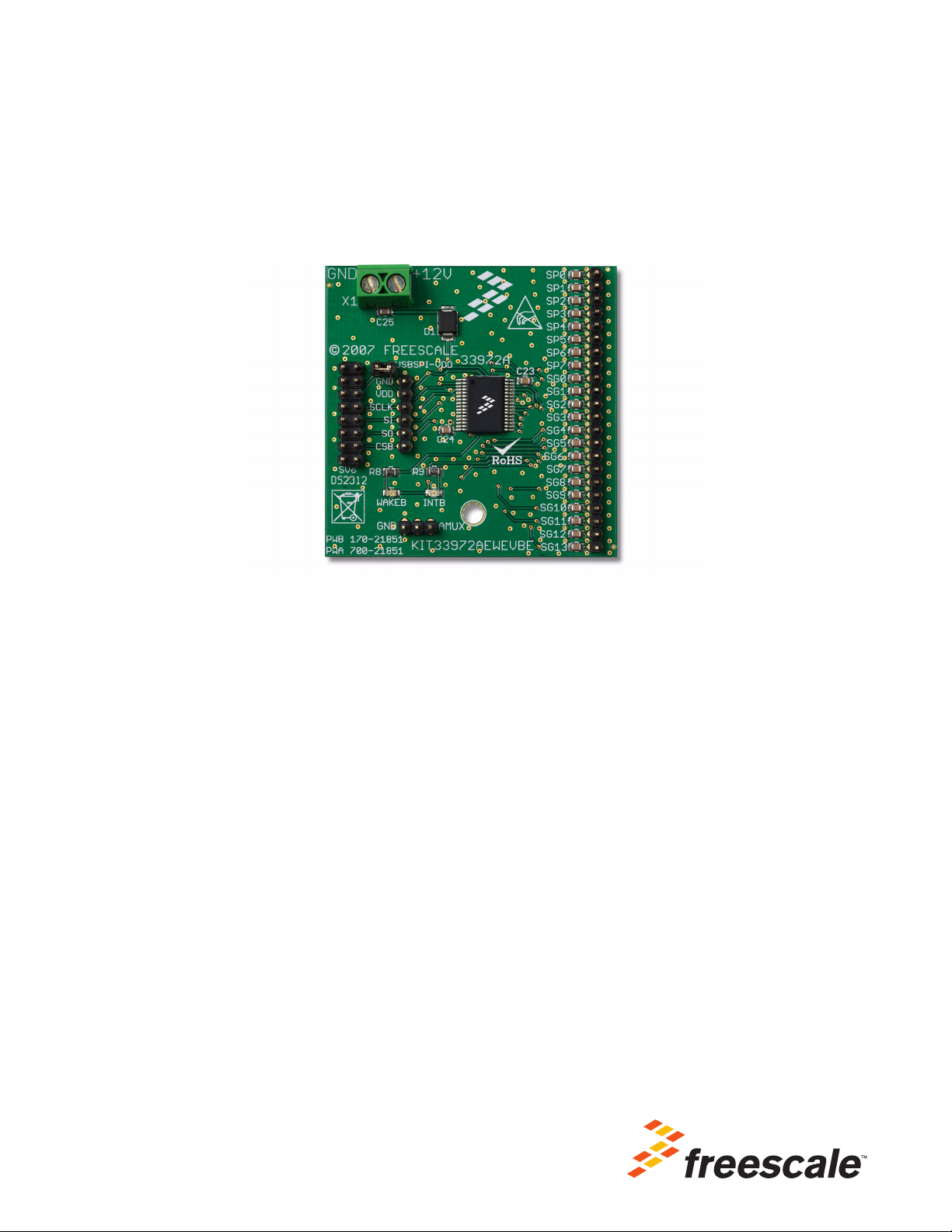
KIT33972AEWEVBE Evaluation Board
Featuring the MC33972A Multiple Switch Detection Interface IC
Figure 1. KIT33972AEWEVBE Evaluation Board
Contents
1 Kit Contents/Packing List . . . . . . . . . . . . . . . . . . . . . . . . . . . . . . . . . . . . . . . . . . . . . . . . . . . . . . . . . . . . . 2
2 Jump Start . . . . . . . . . . . . . . . . . . . . . . . . . . . . . . . . . . . . . . . . . . . . . . . . . . . . . . . . . . . . . . . . . . . . . . . . . 2
3 Important Notice . . . . . . . . . . . . . . . . . . . . . . . . . . . . . . . . . . . . . . . . . . . . . . . . . . . . . . . . . . . . . . . . . . . . 3
4 Introduction . . . . . . . . . . . . . . . . . . . . . . . . . . . . . . . . . . . . . . . . . . . . . . . . . . . . . . . . . . . . . . . . . . . . . . . . 4
5 Evaluation Board Features . . . . . . . . . . . . . . . . . . . . . . . . . . . . . . . . . . . . . . . . . . . . . . . . . . . . . . . . . . . . 4
6 MC33972A Device Features . . . . . . . . . . . . . . . . . . . . . . . . . . . . . . . . . . . . . . . . . . . . . . . . . . . . . . . . . . . 4
7 Accessory Interface Board . . . . . . . . . . . . . . . . . . . . . . . . . . . . . . . . . . . . . . . . . . . . . . . . . . . . . . . . . . . . 5
8 Required Equipment . . . . . . . . . . . . . . . . . . . . . . . . . . . . . . . . . . . . . . . . . . . . . . . . . . . . . . . . . . . . . . . . . 5
9 Evaluation Board Configuration. . . . . . . . . . . . . . . . . . . . . . . . . . . . . . . . . . . . . . . . . . . . . . . . . . . . . . . . . 6
10 Installing SPIGen Freeware on your Computer. . . . . . . . . . . . . . . . . . . . . . . . . . . . . . . . . . . . . . . . . . . . 7
11 Setup and Using the Hardware . . . . . . . . . . . . . . . . . . . . . . . . . . . . . . . . . . . . . . . . . . . . . . . . . . . . . . . . 8
12 Schematic . . . . . . . . . . . . . . . . . . . . . . . . . . . . . . . . . . . . . . . . . . . . . . . . . . . . . . . . . . . . . . . . . . . . . . . . 9
13 Board Layout . . . . . . . . . . . . . . . . . . . . . . . . . . . . . . . . . . . . . . . . . . . . . . . . . . . . . . . . . . . . . . . . . . . . . 10
14 Bill of Material . . . . . . . . . . . . . . . . . . . . . . . . . . . . . . . . . . . . . . . . . . . . . . . . . . . . . . . . . . . . . . . . . . . . 12
15 References . . . . . . . . . . . . . . . . . . . . . . . . . . . . . . . . . . . . . . . . . . . . . . . . . . . . . . . . . . . . . . . . . . . . . . 13
16 Revision History . . . . . . . . . . . . . . . . . . . . . . . . . . . . . . . . . . . . . . . . . . . . . . . . . . . . . . . . . . . . . . . . . . 14
Page 2

Kit Contents/Packing List
Jump Start Your Design
1 Kit Contents/Packing List
• Assembled and tested evaluation board/module in anti-static bag.
• Warranty card
2Jump Start
•Go to www.freescale.com/analogtools
• Locate your kit
• Review your Tool Summary Page
• Look for
• Download documents, software and other information
KT33972UG User’s Guide Rev. 1.0 7/2013
2 Freescale Semiconductor
Page 3

3 Important Notice
Freescale provides the enclosed product(s) under the following conditions:
This evaluation kit is intended for use of ENGINEERING DEVELOPMENT OR EVALUATION
PURPOSES ONLY. It is provided as a sample IC pre-soldered to a printed circuit board to make
it easier to access inputs, outputs, and supply terminals. This evaluation board may be used with
any development system or other source of I/O signals by simply connecting it to the host MCU
or computer board via off-the-shelf cables. This evaluation board is not a Reference Design and
is not intended to represent a final design recommendation for any particular application. Final
device in an application will be heavily dependent on proper printed circuit board layout and heat
sinking design as well as attention to supply filtering, transient suppression, and I/O signal quality.
The goods provided may not be complete in terms of required design, marketing, and or
manufacturing related protective considerations, including product safety measures typically
found in the end product incorporating the goods. Due to the open construction of the product, it
is the user's responsibility to take any and all appropriate precautions with regard to electrostatic
discharge. In order to minimize risks associated with the customers applications, adequate design
and operating safeguards must be provided by the customer to minimize inherent or procedural
hazards. For any safety concerns, contact Freescale sales and technical support services.
Should this evaluation kit not meet the specifications indicated in the kit, it may be returned within
30 days from the date of delivery and will be replaced by a new kit.
Freescale reserves the right to make changes without further notice to any products herein.
Freescale makes no warranty, representation or guarantee regarding the suitability of its products
for any particular purpose, nor does Freescale assume any liability arising out of the application
or use of any product or circuit, and specifically disclaims any and all liability, including without
limitation consequential or incidental damages. “Typical” parameters can and do vary in different
applications and actual performance may vary over time. All operating parameters, including
“Typical”, must be validated for each customer application by customer’s technical experts.
Freescale does not convey any license under its patent rights nor the rights of others. Freescale
products are not designed, intended, or authorized for use as components in systems intended
for surgical implant into the body, or other applications intended to support or sustain life, or for
any other application in which the failure of the Freescale product could create a situation where
personal injury or death may occur.
Should the Buyer purchase or use Freescale products for any such unintended or unauthorized
application, the Buyer shall indemnify and hold Freescale and its officers, employees,
subsidiaries, affiliates, and distributors harmless against all claims, costs, damages, and
expenses, and reasonable attorney fees arising out of, directly or indirectly, any claim of personal
injury or death associated with such unintended or unauthorized use, even if such claim alleges
that Freescale was negligent regarding the design or manufacture of the part.Freescale™ and the
Freescale logo are trademarks of Freescale Semiconductor, Inc. All other product or service
names are the property of their respective owners.
© Freescale Semiconductor, Inc. 2013
Important Notice
KT33972UG User’s Guide Rev. 1.0 7/2013
Freescale Semiconductor, Inc. 3
Page 4

Introduction
4 Introduction
This evaluation kit features the MC33972A Multiple Switch Detection Interface with suppressed wake-up.
The kit is designed to detect the closing and opening of up to 22 switch contacts. The switch status, either
open or closed, is transferred to the microprocessor unit (MCU) through a serial peripheral interface (SPI).
The device also features a 22-to-1 analog multiplexer for reading inputs as analog. The analog input signal
is buffered and provided on the AMUX output pin for the MCU to read.The MC33972A device has two
modes of operation, Normal and Sleep. Normal Mode allows programming of the device and supplies switch
contacts with pull-up or pull-down current as it monitors switch change-of-state. The Sleep Mode provides
low quiescent current, which makes the MC33972A ideal for automotive and industrial products requiring
low sleep-state currents.
5 Evaluation Board Features
The board has the following capabilities:
• The MC33972A device can monitor as many as twenty-two switches and provide their states as
information to a PC for evaluation.
• An onboard 16-pin USB port connects to the PC through the Freescale SPI-to-USB Interface Dongle
(KITUSBSPIDGLEVME). See
Accessory Interface Board.
• The MC33972A device can be programmed using the SPIGen utility running on the PC. See
“
Installing SPIGen Freeware on your Computer”.
• LEDs report the status of the MC33972A Interrupt (INT) and Wake-Up lines.
6 MC33972A Device Features
The MC33972A device supports the following functions:
• Designed to operate 5.5 V ≤ V
• Switch input voltage range -14 V to VPWR, 40 V Max
• Interfaces directly to MPU using 3.3 V/5.0 V SPI protocol
• Selectable wake-up on change of state
• Selectable wetting current (16 or 2.0 mA)
• 8 programmable inputs (switches to battery or ground)
• 14 switch-to-ground inputs
• Typical standby current: V
• Active interrupt (INT) on change-of-switch state
Freescale analog ICs are manufactured using the SMARTMOS process, a combinational BiCMOS
manufacturing flow that integrates precision analog, power functions and dense CMOS logic together on a
single cost-effective die.
PWR
≤ 26V
PWR
= 100 µA and VDD = 20 µA
KT33972UG User’s Guide Rev. 1.0 7/2013
4 Freescale Semiconductor
Page 5
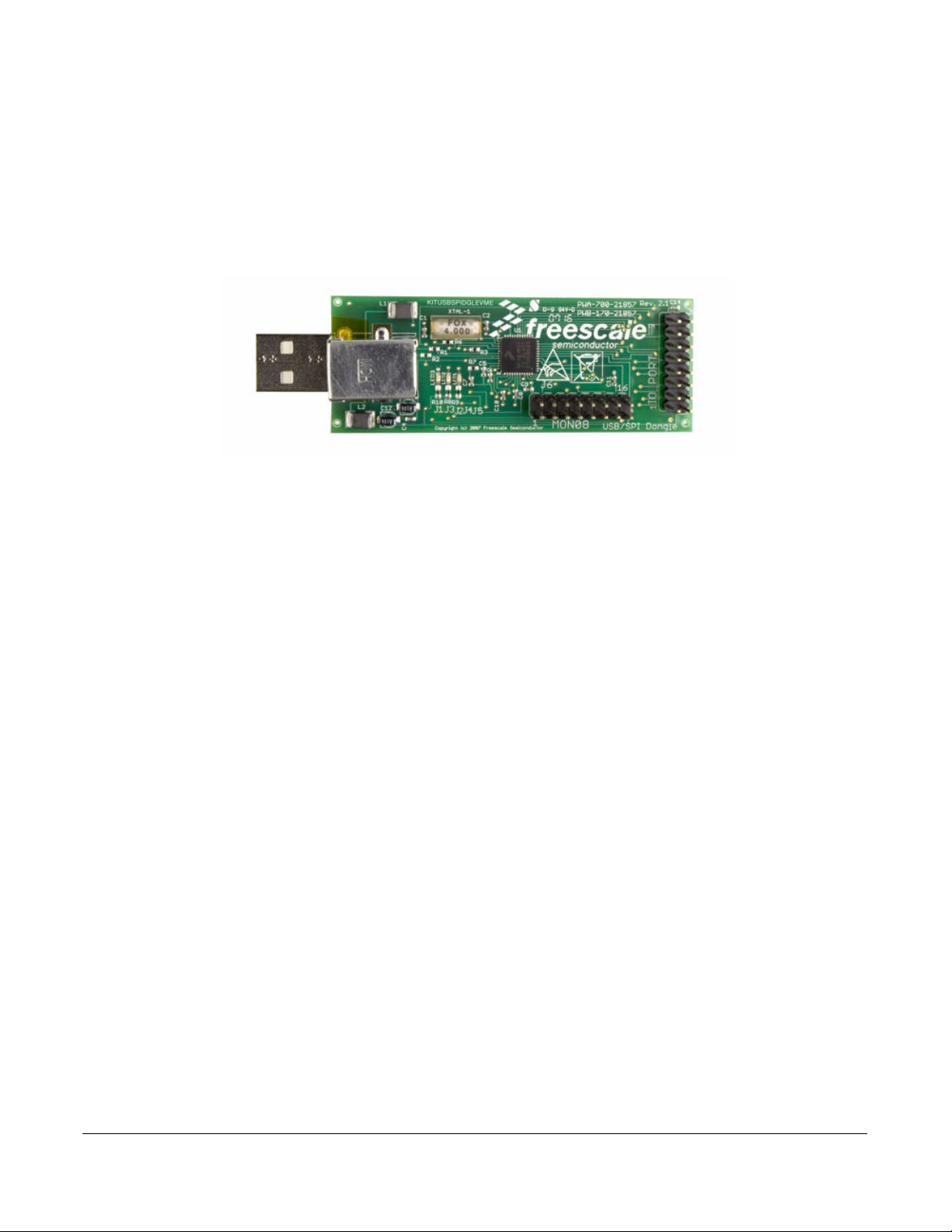
7 Accessory Interface Board
The KIT33972AEWEVBE board may be used with the KITUSBSPIDGLEVME interface dongle (shown
below), which provides a USB-to-SPI interface. This small board makes use of the USB and SPI ports built
into Freescale’s MC68HC908JW32 microcontroller. The main function provided by this dongle is to allow
Freescale evaluation boards that have an SPI port to communicate with a PC through its USB port.
Figure 2. KITUSBSPIDGLEVME Interface Dongle
Accessory Interface Board
8 Required Equipment
Minimum equipment required:
• DC power supply
• USB-enabled PC with Windows XP or higher
• KITUSBSPIDGLEVME Interface Dongle
KT33972UG User’s Guide Rev. 1.0 7/2013
Freescale Semiconductor, Inc. 5
Page 6
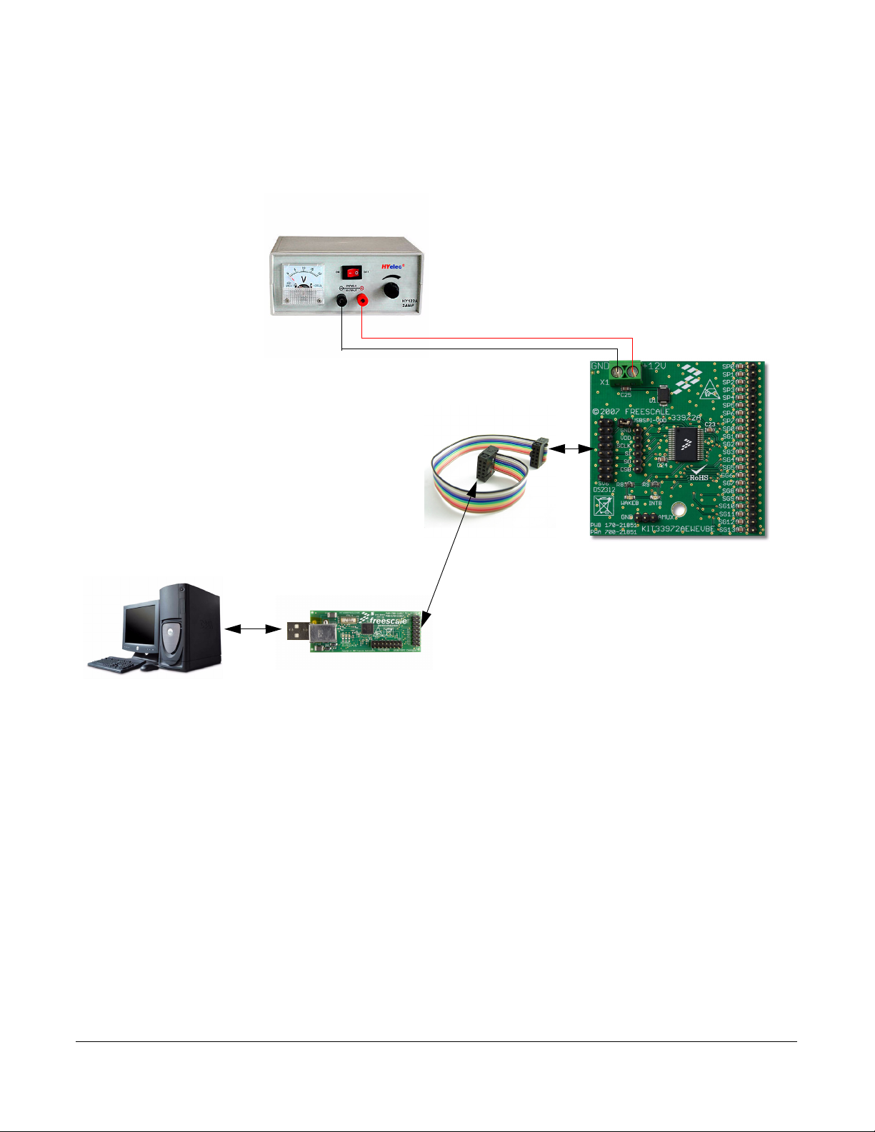
Evaluation Board Configuration
Power Supply
GND
+12V
KIT33972AEWEVBE
USB/SPI Dongle
(KITUSBSPIDGLEVME)
16-Pin SPI Ribbon
Cable
9 Evaluation Board Configuration
Figure 3. KIT33972AEWEVBE plus KITUSBSPIDGLEVME Board Setup
KT33972UG User’s Guide Rev. 1.0 7/2013
6 Freescale Semiconductor
Page 7
Installing SPIGen Freeware on your Computer
10 Installing SPIGen Freeware on your Computer
The latest version of SPIGen is designed to run on any Windows 8, Windows 7, Vista or XP-based operating
system. To install the software, go to
to open the corresponding Tool Summary Page. Look for “Jump Start Your Design”. Download to your
computer desktop the SPIGen software as well as the associated configuration file.
Run the install program from the desktop. The Installation Wizard will guide you through the rest of the
process.
To use SPIGen, go to the Windows Start menu, then Programs, then SPIGen, and click on the SPIGen icon.
The SPIGen Graphic User Interface (GUI) will appear. Go to the file menu in the upper left hand corner of
the GUI, and select “Open”. In the file selection window that appears, set the “Files of type:” drop-down
menu to “SPIGen Files (*.spi)”. (As an exceptional case, the file name may have a .txt extension, in which
case you should set the menu to “All Files (*.*)”.) Next, browse for the configuration file you saved on your
desktop earlier and select it. Click “Open”, and SPIGen will create a specially configured SPI command
generator for your evaluation board.
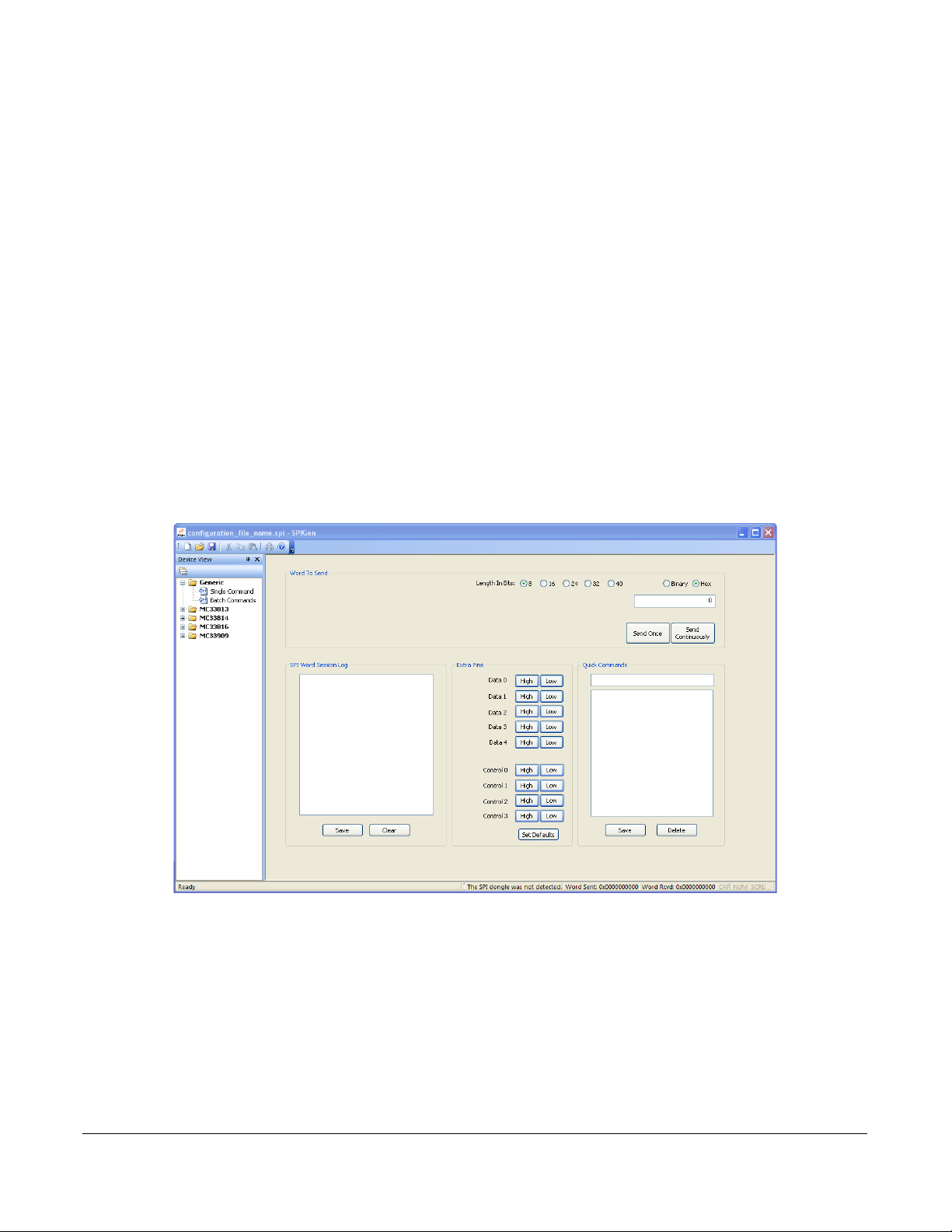
The GUI is shown in Figure 4. The text at the top is the name of the configuration file loaded. The left side
panel displays folders that group user interfaces. The process of loading the configuration file has assigned
a list of “Extra Pins” as well as a list “Quick Commands”, all of which are board-specific.
www.freescale.com/analogtools and select your kit. Click on that link
Figure 4. SPIGen GUI
KT33972UG User’s Guide Rev. 1.0 7/2013
Freescale Semiconductor, Inc. 7
Page 8

Setup and Using the Hardware
11 Setup and Using the Hardware
In order to perform the demonstration examples, first set up the evaluation board hardware and software as
follows:
1. The KIT33972AEWEVBE evaluation board allows the customer to quickly evaluate features of the
device with a simple bench top setup. All switch inputs may be evaluated using the onboard switch
banks or actual system switches connected to the switch input edge connector.
2. Using a standard USB cable, the USB to SPI dongle board and the enclosed SPIGen SPI Driver
software, you can use a personal computer to provide the Serial Peripheral Interface (SPI)
communication with this EVB. (See
3. Connect power supply to the +12 V and GND terminals on the EVB's power terminal block. Make sure
the voltages provided are in accordance with the device data sheet and that the supply currents are
sufficient to supply the switch contact wetting current.
4. With power applied to the KIT33972AEWEVBE Evaluation board, the 33972A device will be in
NORMAL mode with both LEDs illuminated. The 33972A device is now ready to receive SPI
commands and be configured via SPI to read the switch inputs. External switches may be used to
evaluate the device.
5. To use SPIGen, go to the Windows Start menu, then Programs, then SPIGen, and click on the SPIGen
icon. The SPIGen GUI will appear. Loading of the configuration file specific to theKIT33972AEWEVBE
board is described in section “
configuration file, SPIGen will open a specifically configured SPI command generator for the
evaluation board. The configuration file will set all parameters for SPI signals from the PC and provide
a list of commands that may be sent to the EVB.
6. To initialize the MCZ33972AEW device to read switch inputs, the user may use batch commands. To
do this, select the “Batch Commands” option inside the “Generic” folder on the left-hand panel. In the
window that appears, select “Full Initialize” from the “Batch Name” drop-down menu. To send this
batch of commands to the evaluation board, click the “Send Once” tab.
7. To quickly evaluate the board as well as the MCZ33972AEW device, simply select the “Single
Command” option inside the “Generic” folder on the left-hand panel. In the window that appears, select
the “Switch Status” command from the “Quick Commands” list, then click the “Send Continuously”
button. The opening and closing of switches may now be seen in the “Word Rcvd” field located at the
bottom of the SPIGen GUI. Refer to the MCZ33972AEW data sheet for detailed information on I/O
communication and device operation.
Evaluation Board Configuration.)
Installing SPIGen Freeware on your Computer”. Once having loaded the
KT33972UG User’s Guide Rev. 1.0 7/2013
8 Freescale Semiconductor
Page 9

12 Schematic
Schematic
Figure 5. Evaluation Board Schematic
KT33972UG User’s Guide Rev. 1.0 7/2013
Freescale Semiconductor, Inc. 9
Page 10

Board Layout
13 Board Layout
13.1 Assembly Layer Top
KT33972UG User’s Guide Rev. 1.0 7/2013
10 Freescale Semiconductor
Page 11
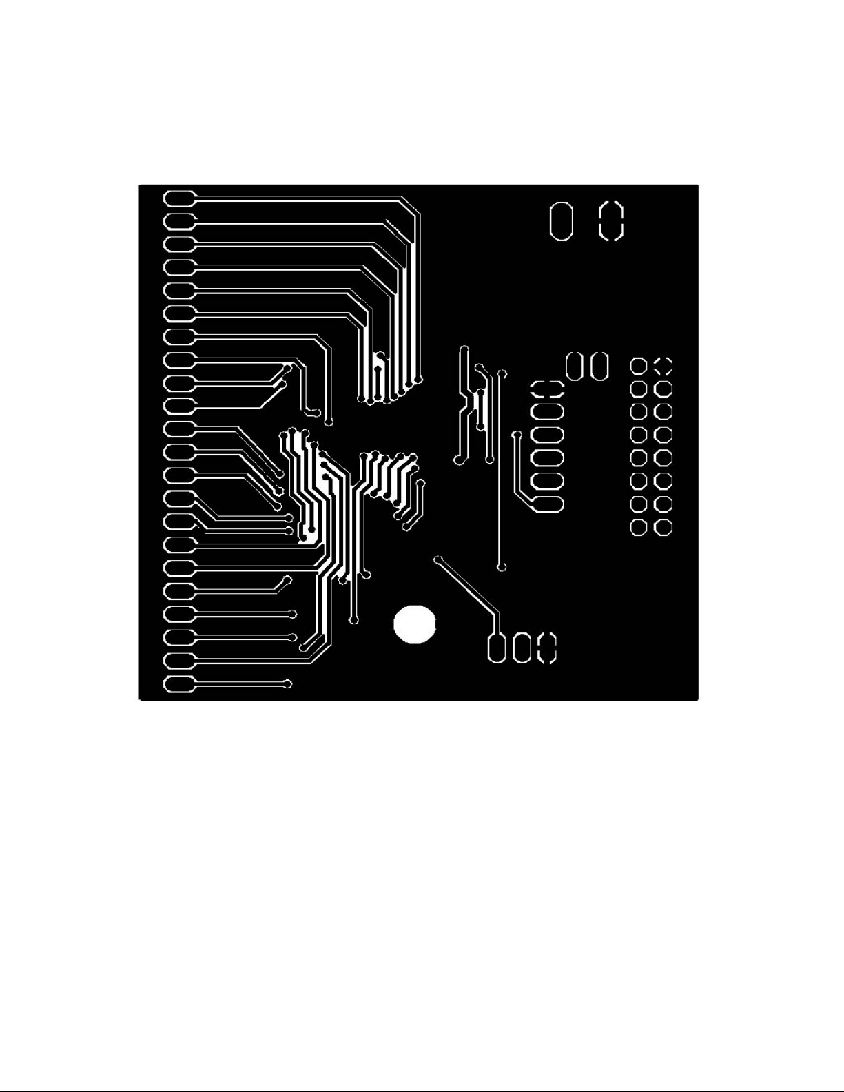
13.2 Bottom Layer Routing
Note: This image is an exception to the standard top-view mode of representation used in this document. It has been flipped
to show a bottom view.
Board Layout
KT33972UG User’s Guide Rev. 1.0 7/2013
Freescale Semiconductor, Inc. 11
Page 12

Bill of Material
14 Bill of Material
Qty
Integrated Circuits
Diodes
LEDs
Capacitors
Resistors
Switches, Connectors, and Board
Schematic
Label
1 MC33972AEW Freescale MC339972AEW SO-32WB
1 D1 1.0 amp Schottky Diode MURS120T3G SMB
1 WAKEB Green Through Hole LED 2.5 mm LED
1 INTB Red Through Hole LED 2.5 mm LED
25 C1-C25 100 nF 50V X7R CAP C0805
2 R8, R9 1.0 K 5% Resistor R0805
1 JP1 1 x 2 Pin Header Straight
Value Description Package
1 SV3,JP1 1 x 3 Pin Header Straight
1 SV4,JP1 1 x 6 Pin Header Straight
1 SV6 2 x 8 Pin Header Straight
1 SV1,SV2
SV5
1 X1 AK500/2 2-Terminal Power Connector
1 2.3" X 3.0" X 0.062" EVB Circuit Board 1 oz. Copper
Note: Freescale does not assume liability, endorse, or warrant components from external manufacturers that are referenced in circuit drawings
or tables. While Freescale offers component recommendations in this configuration, it is the customer’s responsibility to validate their application.
1 x 22 Pin Header 90 Degree
KT33972UG User’s Guide Rev. 1.0 7/2013
12 Freescale Semiconductor
Page 13

15 References
Following are URLs where you can obtain information on related Freescale products and application
solutions:
References
Freescale.com
Support Pages
MC33972A
Product Summary Page
KIT33972AEWEVBE
Tool Summary Page
KITUSBSPIDGLEVME
Tool Summary Page
SPIGen
Tool Summary Page
Analog Home Page http://www.freescale.com/analog
Automotive Home Page http://www.freescale.com/automotive
http://www.freescale.com/webapp/sps/site/prod_summary.jsp?code=MC33972A
http://www.freescale.com/webapp/sps/site/prod_summary.jsp?code=KIT33972AEWEVBE
http://www.freescale.com/webapp/sps/site/prod_summary.jsp?code=KITUSBSPIDGLEVME
http://www.freescale.com/files/soft_dev_tools/software/device_drivers/SPIGen.html
15.1 Support
Visit www.freescale.com/support for a list of phone numbers within your region.
15.2 Warranty
Visit www.freescale.com/warranty for a list of phone numbers within your region.
URL
KT33972UG User’s Guide Rev. 1.0 7/2013
Freescale Semiconductor, Inc. 13
Page 14

Revision History
16 Revision History
Revision Date Description of Changes
1.0
7/2013 • Initial Release
KT33972UG User’s Guide Rev. 1.0 7/2013
14 Freescale Semiconductor
Page 15

How to Reach Us:
Home Page:
freescale.com
Web Support:
freescale.com/support
Information in this document is provided solely to enable system and software implementers to use Freescale
products. There are no express or implied copyright licenses granted hereunder to design or fabricate any
integrated circuits based on the information in this document.
Freescale reserves the right to make changes without further notice to any products herein. Freescale makes no
warranty, representation, or guarantee regarding the suitability of its products for any particular purpose, nor does
Freescale assume any liability arising out of the application or use of any product or circuit, and specifically
disclaims any and all liability, including without limitation consequential or incidental damages. “Typical” parameters
that may be provided in Freescale data sheets and/or specifications can and do vary in different applications, and
actual performance may vary over time. All operating parameters, including “typicals,” must be validated for each
customer application by customer’s technical experts. Freescale does not convey any license under its patent rights
nor the rights of others. Freescale sells products pursuant to standard terms and conditions of sale, which can be
found at the following address: freescale.com/SalesTermsandConditions.
Freescale and the Freescale logo are trademarks of Freescale Semiconductor, Inc., Reg. U.S. Pat. & Tm. Off.
SMARTMOSis a trademark of Freescale Semiconductor, Inc. All other product or service names are the property
of their respective owners.
© 2013 Freescale Semiconductor, Inc.
Document Number: KT33972UG
Rev. 1.0
7/2013
 Loading...