

Page 1
Freescale Semiconductor
User’s Guide
Document Number: KT33926UG
Rev. 2.0, 12/2012
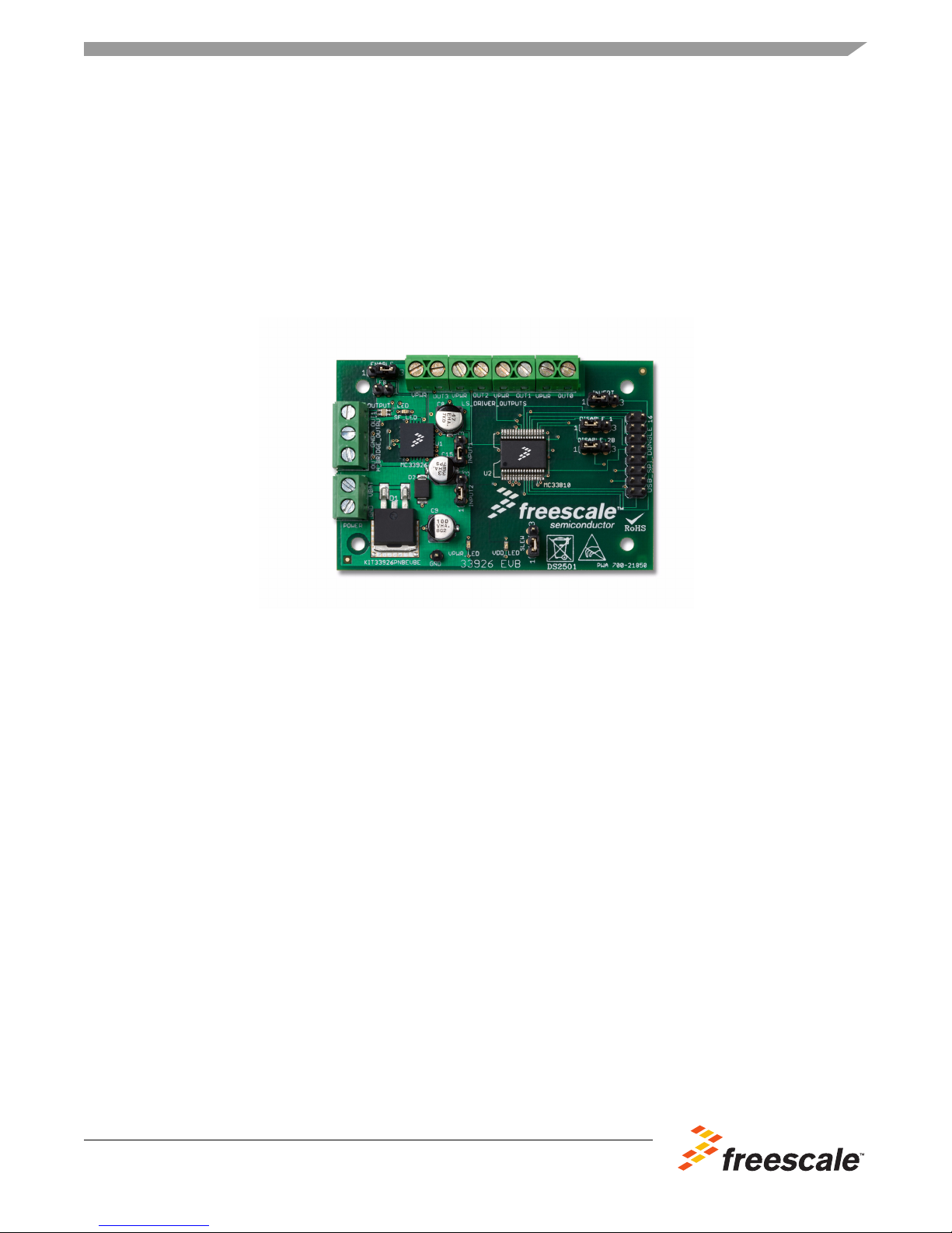
KIT33926PNBEVBE Evaluation Board User’s Guide
Featuring the MC33926 5.0A Throttle Control H-Bridge IC with Slew Rate Control
and the MC33810 Automotive Engine Control IC
Figure 1. KIT33926PNBEVBE Evaluation Board
Table of Contents
1 Kit Contents / Packing List . . . . . . . . . . . . . . . . . . . . . . . . . . . . . . . . . . . . . . . . . . . . . . . . . . . . . . . . . . . . . . . . . . . . . . 2
2 Important Notice . . . . . . . . . . . . . . . . . . . . . . . . . . . . . . . . . . . . . . . . . . . . . . . . . . . . . . . . . . . . . . . . . . . . . . . . . . . . . . 3
3 Introduction . . . . . . . . . . . . . . . . . . . . . . . . . . . . . . . . . . . . . . . . . . . . . . . . . . . . . . . . . . . . . . . . . . . . . . . . . . . . . . . . . . 4
4 Evaluation Board Features . . . . . . . . . . . . . . . . . . . . . . . . . . . . . . . . . . . . . . . . . . . . . . . . . . . . . . . . . . . . . . . . . . . . . . 4
5 MC33926 Device Features . . . . . . . . . . . . . . . . . . . . . . . . . . . . . . . . . . . . . . . . . . . . . . . . . . . . . . . . . . . . . . . . . . . . . . 4
6 MC33810 Device Features . . . . . . . . . . . . . . . . . . . . . . . . . . . . . . . . . . . . . . . . . . . . . . . . . . . . . . . . . . . . . . . . . . . . . . 4
7 Required Equipment . . . . . . . . . . . . . . . . . . . . . . . . . . . . . . . . . . . . . . . . . . . . . . . . . . . . . . . . . . . . . . . . . . . . . . . . . . . 5
8 Evaluation Board Configuration . . . . . . . . . . . . . . . . . . . . . . . . . . . . . . . . . . . . . . . . . . . . . . . . . . . . . . . . . . . . . . . . . . 5
9 Installing SPIGen Freeware on your Computer . . . . . . . . . . . . . . . . . . . . . . . . . . . . . . . . . . . . . . . . . . . . . . . . . . . . . . 6
10 EVB Setup and Using the Hardware. . . . . . . . . . . . . . . . . . . . . . . . . . . . . . . . . . . . . . . . . . . . . . . . . . . . . . . . . . . . . . 7
11 Evaluation Board Hardware Description . . . . . . . . . . . . . . . . . . . . . . . . . . . . . . . . . . . . . . . . . . . . . . . . . . . . . . . . . . . 8
12 Schematic . . . . . . . . . . . . . . . . . . . . . . . . . . . . . . . . . . . . . . . . . . . . . . . . . . . . . . . . . . . . . . . . . . . . . . . . . . . . . . . . . 13
13 Board Layout. . . . . . . . . . . . . . . . . . . . . . . . . . . . . . . . . . . . . . . . . . . . . . . . . . . . . . . . . . . . . . . . . . . . . . . . . . . . . . . 14
14 Bill of Material . . . . . . . . . . . . . . . . . . . . . . . . . . . . . . . . . . . . . . . . . . . . . . . . . . . . . . . . . . . . . . . . . . . . . . . . . . . . . . 20
15 References . . . . . . . . . . . . . . . . . . . . . . . . . . . . . . . . . . . . . . . . . . . . . . . . . . . . . . . . . . . . . . . . . . . . . . . . . . . . . . . . 23
16 Revision History . . . . . . . . . . . . . . . . . . . . . . . . . . . . . . . . . . . . . . . . . . . . . . . . . . . . . . . . . . . . . . . . . . . . . . . . . . . . 24
© Freescale Semiconductor, Inc., 2012. All rights reserved.
Page 2

Kit Contents / Packing List
1 Kit Contents / Packing List
• Assembled and tested evaluation board/module in anti-static bag.
• Ribbon cable assembly with 16-pin connector
• CD-ROM containing:
• Supporting documentation for featured device (including data sheet and user's guide)
– Schematic of evaluation board
–PCB artwork
– Bill of material for evaluation board
– Instruction sheet for evaluation board
• SPIGen 5.0.1 software
• Warranty card
2 Freescale Semiconductor
KT33926UG, Rev. 2.0
Page 3

2 Important Notice
Freescale provides the enclosed product(s) under the following conditions:
This evaluation kit is intended for use of ENGINEERING DEVELOPMENT OR EVALUATION
PURPOSES ONLY. It is provided as a sample IC pre-soldered to a printed circuit board to make it easier
to access inputs, outputs, and supply terminals. This EVB may be used with any development system or
other source of I/O signals by simply connecting it to the host MCU or computer board via off-the-shelf
cables. This EVB is not a Reference Design and is not intended to represent a final design
recommendation for any particular application. Final device in an application will be heavily dependent
on proper printed circuit board layout and heat sinking design as well as attention to supply filtering,
transient suppression, and I/O signal quality.
The goods provided may not be complete in terms of required design, marketing, and or manufacturing
related protective considerations, including product safety measures typically found in the end product
incorporating the goods. Due to the open construction of the product, it is the user's responsibility to take
any and all appropriate precautions with regard to electrostatic discharge. In order to minimize risks
associated with the customers applications, adequate design and operating safeguards must be provided
by the customer to minimize inherent or procedural hazards. For any safety concerns, contact Freescale
sales and technical support services.
Should this evaluation kit not meet the specifications indicated in the kit, it may be returned within 30 days
from the date of delivery and will be replaced by a new kit.
Freescale reserves the right to make changes without further notice to any products herein. Freescale
makes no warranty, representation or guarantee regarding the suitability of its products for any particular
purpose, nor does Freescale assume any liability arising out of the application or use of any product or
circuit, and specifically disclaims any and all liability, including without limitation consequential or
incidental damages. “Typical” parameters can and do vary in different applications and actual
performance may vary over time. All operating parameters, including “Typical”, must be validated for each
customer application by customer’s technical experts.
Freescale does not convey any license under its patent rights nor the rights of others. Freescale products
are not designed, intended, or authorized for use as components in systems intended for surgical implant
into the body, or other applications intended to support or sustain life, or for any other application in which
the failure of the Freescale product could create a situation where personal injury or death may occur.
Important Notice
Should the buyer purchase or use Freescale products for any such unintended or unauthorized
application, the buyer shall indemnify and hold Freescale and its officers, employees, subsidiaries,
affiliates, and distributors harmless against all claims, costs, damages, and expenses, and reasonable
attorney fees arising out of, directly or indirectly, any claim of personal injury or death associated with
such unintended or unauthorized use, even if such claim alleges that Freescale was negligent regarding
the design or manufacture of the part. Freescale™ and the Freescale logo are trademarks of Freescale
Semiconductor, Inc. All other product or service names are the property of their respective owners.
© Freescale Semiconductor, Inc. 2012
KT33926UG, Rev. 2.0
Freescale Semiconductor 3
Page 4

Introduction
3 Introduction
The KIT33926PNBEVBE Evaluation Board (EVB) is an easy-to-use circuit board that allows the user to
exercise all the functions of the MC33926 H-Bridge circuit. The EVB communicates to a PC through a
USB/SPI Dongle connected to the PC’s USB port. The Freescale SPIGen program provides the User
Interface to the MC33926 EVB’s SPI port and allows the user to send commands to and receive error
messages from the IC. There is also a MC33810 circuit on the EVB which contains four, low side, drivers
and four General Purpose MOSFET Gate drivers which are used to provide PWM signals to the various
MC33926 inputs.
4 Evaluation Board Features
• A MC33926 H-Bridge IC
• A MC33810 PWM Driver (IID) IC
• A USB to SPI Dongle interface, through which 5V power is supplied
• Power conditioning circuitry
• A set of seven Input Select Jumpers.
5 MC33926 Device Features
This MC33926 is designed primarily for automotive electronic throttle control, but is applicable to any
low-voltage DC servo motor control application within the current and voltage limits stated in this
specification. This device has the following features:
• 8.0 V to 28 V Continuous Operation (Transient Operation from 5.0 V to 40 V)
• 225 m maximum RDS(ON) @ 150°C (each H-Bridge MOSFET)
• 3.0 V and 5.0 V TTL / CMOS Logic Compatible Inputs
• Overcurrent Limiting (Regulation) via Internal Constant-Off-Time PWM
• Output Short Circuit Protection (Short to VPWR or Ground)
• Temperature-Dependant Current-Limit Threshold Reduction
• All Inputs have an Internal Source/Sink to Define the Default (Floating Input) States
• Sleep Mode with Current Draw < 50 µA (with Inputs Floating or Set to Match Default Logic States)
6 MC33810 Device Features
The MC33810 is an eight channel output driver IC intended for automotive engine control applications.
This device has the following features:
• Designed to Operate over the range of 4.5 V ≤ VPWR ≤ 36 V
• Quad Ignition IGBT or MOSFET gate pre-driver with Parallel/SPI and/or PWM Control
• Quad Injector Driver with Parallel/SPI Control
• Interfaces Directly to MCU Using 3.3 V / 5.0 V SPI Protocol
• Injector Driver Current Limit - 4.5A Typical
• Independent Fault Protection and Diagnostics
• VPWR Standby Current 10 µA Typical
4 Freescale Semiconductor
KT33926UG, Rev. 2.0
Page 5
7 Required Equipment
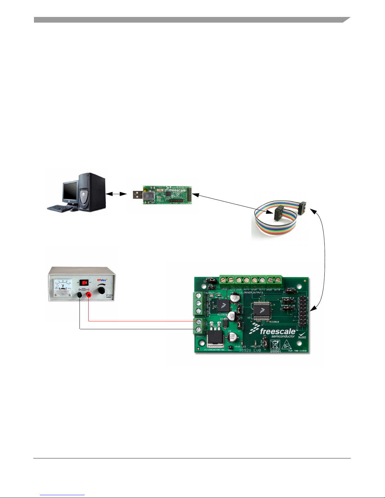
USB/SPI Dongle
(KITUSBSPIDGLEVME)
Throttle Control H-Bridge
(KIT33926PNBEVBE)
16-Pin SPI Ribbon
Cable
Power Supply
GND
VBAT
Minimum required equipment:
• USB enabled Computer with Windows XP or higher
• SPIGen 7.0 or greater
• One of the following two USB-to-SPI kits:
• USB/SPI Dongle board (KITUSBSPIDGLEVME) plus 16-Pin Ribbon Cable
• Typical loads (DC servo motor, fuel injectors, solenoids, lamps, and relays)
8 Evaluation Board Configuration
Required Equipment
Figure 2. Evaluation Board Setup
Freescale Semiconductor 5
KT33926UG, Rev. 2.0
Page 6
Installing SPIGen Freeware on your Computer
9 Installing SPIGen Freeware on your Computer
There current version of SPIGen is designed to run on a USB enabled computer with Windows XP,
Windows 2000, or Windows NT.
This version of SPIGen includes a README.txt file which will describe the operating systems where the
software should be installed. Before you install the program, refer to the SPIGen README.txt file to check
the compatibility of the installation program and your computer operating system.
To install the software from the CD-ROM, insert the CD-ROM into your CD drive. Click the Start button,
and then click “Run…”.
While running Windows NT, Windows 2000, or Windows XP, type
“D:\SPIGen_Win_NT_2000_XP\Setup.exe” in the box, and then click “OK”.
Several temporary files will be copied to your computer, and then the Installation Wizard will guide you
through the rest of the process.
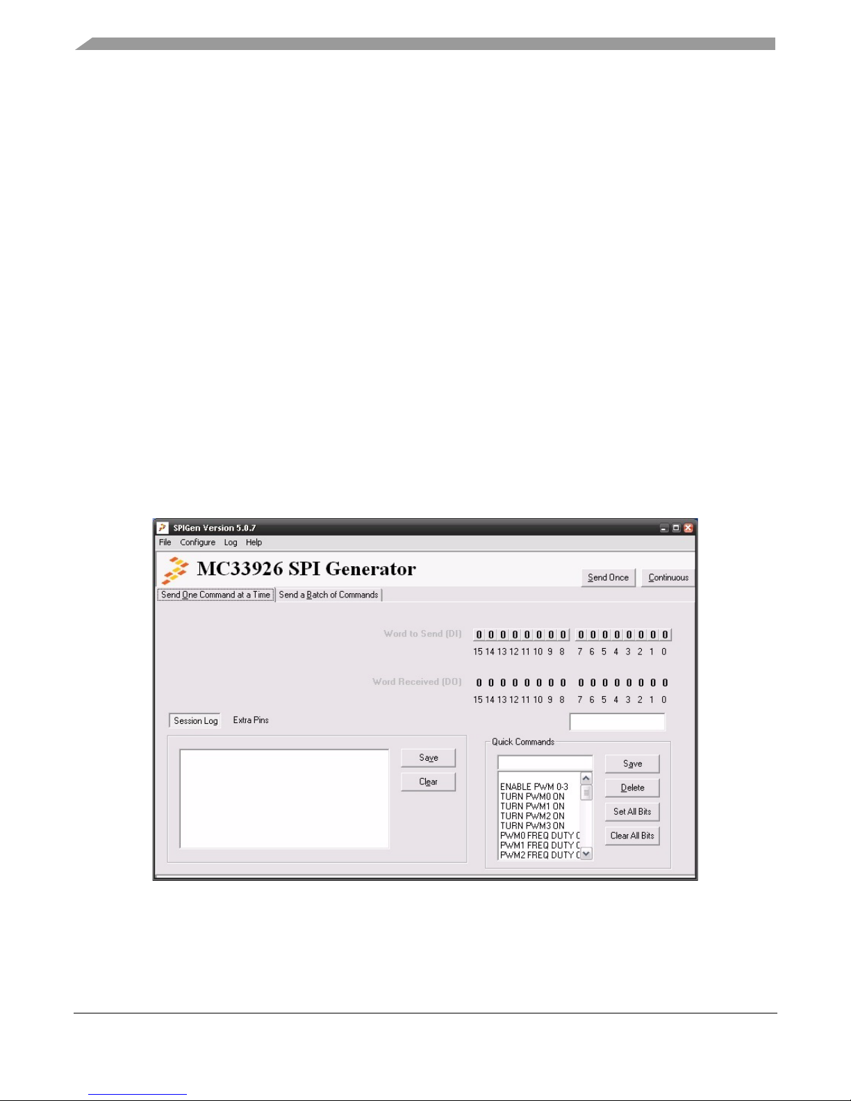
To use SPIGen, Go to the Windows Start menu, then Programs, then SPIGen, and click on the SPIGen
icon. The SPIGen “Generic SPI Generator” graphic user interface (GUI) will appear. Go to the File menu
in the upper left hand corner of the GUI, and select Open, then browse the CD to find and select the
SPIGen Configuration “.spi” file for the EVB you are using. Click Open, and SPIGen will open a
specifically configured SPI command generator for your EVB.
6 Freescale Semiconductor
Figure 3. SPI Generator GUI
KT33926UG, Rev. 2.0
Page 7

10 EVB Setup and Using the Hardware
To perform the examples included in the CD the following connections and setup must be performed:
1.Make sure the SPIGen 5.0X program is installed on the PC and it can communicate with the USB/SPI Dongle as
described in that kit’s documentation.
2.Connect the USB/SPI Dongle to the MC33926 EVB via a 16 pin ribbon cable. Make sure to orient the cable so that
pin1 on both the USB/SPI Dongle and the MC33926 EVB are connected correctly, pin 1 to pin 1.
3.Connect the USB/SPI Dongle to a PC, LED 2 on the USB/SPI Dongle and the VDD LED on the MC33926 board
should both be illuminated.
4.Attach a +12 VDC supply (do not turn on power yet) to the power connector on the MC33926 EVB, making sure to
observe the GND and +12 V terminals. The current capability of the +12 V supply should exceed the maximum
total current that the number of simultaneously ON loads will require.
5.Attach loads to the MC33810 OUT0 - OUT3 terminals between the VPWR terminals and the OUTx terminals. One
possible demo load is a 10 W halogen G4 Base T3 bulb (used in landscape lighting applications). This load will
draw approximately 850 mA and fits nicely into the screw terminals.
6.Attach 10 W halogen G4 Base T3 bulbs to the H-Bridge OUT1 and OUT-2 terminals from OUT1 to GND and
another load from OUT2 to GND.
7.Launch SPIGen and from the “File” menu, select “Open” and browse to the CD containing the
“MC33926_EVB_CONFIGURATION_FILE.spi” file. The title on the SPIGen screen should change from
“Generic SPI Generator” to “MC33926 SPI Generator”.
EVB Setup and Using the Hardware
8.Turn on the +12 Volt Supply. The bulbs connected to the H-Bridge OUT1 and OUT2 should illuminate immediately.
Verify that all is working correctly by clicking on the “Extra Pins” button in the SPIGen main screen and then click
on the DATA 0 “High” button. The OUT1 bulb should extinguish. Clicking on the DATA 1 “High” button should
extinguish the OUT2 bulb.
9.Click on the Control 0 “High” button. The bulb connected to OUT0 on the MC33926 EVB and LED1 on the
USB/SPI Dongle should be illuminated. Click on the Control 0 “Low” button and the bulb connected to OUT0 and
LED1 on the USB/SPI Dongle.
Freescale Semiconductor 7
KT33926UG, Rev. 2.0
Page 8
Evaluation Board Hardware Description
Reverse Battery
And Transi ent
Protecti on
MC33810
33810
OUT0 –
OUT3
Screw
Connectors
MC 33926
H-Br idge
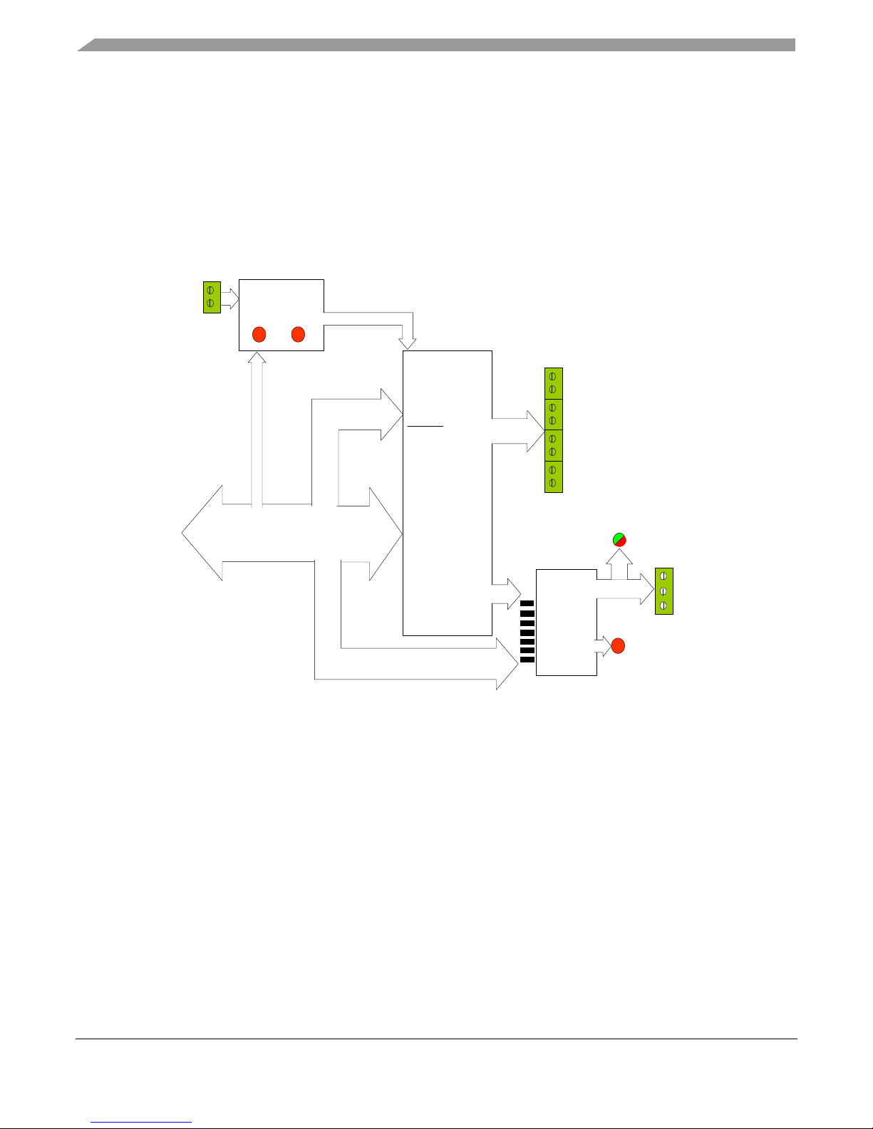
MC33926 Evaluation Board Block Diagram
4
4
2
16 conductor Flat Cable
SO, SI ,
CSB,
CLK
4
SPI
Port
DIN0-3
GIN0- 3
VPWR
LED
8 paral lel contr ol
lines
OUT0 -3
GD1- 3
VBat
2
VPWR,
VDD
RED/GREEN
OUTPUT LED
TO
USB/SPI
DONGLE
VDD
LED
H-BRI DGE
OUT1 OUT2
Screw
Connectors
VDD
`
EN
DISABLE _1
DISABLE _2B
INPUT 1
INPUT 2
INVERT
SLEW
FAULT
LED
3 paral lel contr ol line s
JUMPERS
11 Evaluation Board Hardware Description
This EVB consists of a 33926 H-Bridge, a 33810 PWM Driver (IID) circuit, a USB to SPI Dongle interface,
power conditioning circuitry, and a set of seven Input Select Jumpers. All +5.0
by the EVB is obtained via the USB/SPI Dongle interface. The Hardware Block Diagram is shown below:
volt VDD power required
11.1 LED Display
Several LED’s are provided as visual output devices for the MC33926 EVB board. A list of the LED
devices is shown below:
8 Freescale Semiconductor
1.VDD LED - Indicates when a +5.0 Volt supply is connected
2.VPWR LED - Indicates when +12 Volt supply is connected
3.Fault LED - Illuminates when the MC33926 detects a fault
4.Output LED - Red/Green LED that indicates which direction the current is flowing in the legs of the H-Bridge.
Figure 4. 33926 EVB Block Diagram
KT33926UG, Rev. 2.0
Page 9

11.2 I/O Jumper Definitions (J3)
The EVB contains seven jumpers that connect the inputs of the 33926 as follows (Bold = factory setting):
NAME Position Connection
INPUT 1 1-2/DATA0 2-3/BGD0
INPUT 12 1-2/DATA1 2-3/BGD1
INVERT 1-2/GND 2-3/DATA4
ENABLE 1-2/GND 2-3/VDD
DISABLE_1 1-2/GND 2-3/BGD2
DISABLE_2B 1-2/VDD 2-3/BGD3
SLEW 1-2/GND 2-3/VDD
The DATA0 -DATA4 signals are parallel outputs from the USB/SPI Dongle that can be controlled directly
from the SPIGen program. The BGD0 - BGD3 signals are the outputs of the MC33810 pre-drivers (GD0
-GD3) after being buffered by discrete MOSFETS. (See the schematic for detailed information) The GD0
- GD3 outputs can be set-up to provide a PWM signal, to vary the H-Bridge output. The buffered PWM
signals (BGD0 - BGD3)can be selected via the jumpers to be connected to the Input 1, Input 2, Disable_1
or Disable_2B inputs. This flexibility is provided to illustrate the many ways the MC33926 can be driven
to achieve the same result. An example configuration file called
“MC33926_EVB_CONFIGURATION_FILE.spi” is provided on the CD which contains batch file
examples. In these batch file examples are the instructions to set-up the MC33810 to PWM the GDx
outputs. The MC33810 data sheet (also on the CD provided) describes, in detail, the way to set the PWM
frequency and duty cycle for each of the GD outputs (and corresponding BGDx outputs).
If the user prefers to supply the various MC33926 input signals externally, other than from the USB-SPI
Interface or the PWM signals (BGDx), the jumpers can be removed and connections can be made to the
open pin number 2’ s.
Evaluation Board Hardware Description
11.3 USB/SPI Dongle Connector
The USB/SPI dongle connector is a 16 pin,.1” center, dual-row connector that is designed to interface
directly to the USB/SPI Dongle unit. The USB/SPI dongle connector consists of the following 16 pins:
Number Name Description
1 CSB SPI signal, Chip Select Bar
2 CNTL2 Parallel port signal CNTL2
3 SO SPI signal, Serial Out
4 CNTL1 Parallel port signal CNTL1
5 SI SPI signal, Serial In
6 CNTL0 Parallel port signal CNTL0
Freescale Semiconductor 9
KT33926UG, Rev. 2.0
Page 10

Evaluation Board Hardware Description
Power Terminal
SPI/USB Dongle
Connector
Connector
H-Bridge Output
Connector
MC33810 Output
Terminal Connector
Number Name Description
7 SCLK SPI signal, Serial Clock
8 DATA4 Parallel port signal DATA4
9 CNTL3 Parallel port signal CNTL3
10 DATA3 Parallel port signal DATA3
11 VDD +5 Volt VDD from USB
12 DATA2 Parallel port signal DATA2
13 NC Unused
14 DATA1 Parallel port signal DATA1
15 GND Signal Ground
16 DATA0 Parallel port signal DATA0
This connector mates with the 16 conductor flat cable that connects to the USB/SPI Dongle
(KITUSBSPIDGLEVME).
11.4 Screw Terminal Connections -
The MC33926PNBEVBE board contains input and output screw terminal connections to allow easy
access to the MC33926’s drive circuits.
The diagram below shows the locations of the screw terminals and their functional definitions:
Figure 5. PCB Top Assembly Layer with Screw-Terminal Connectors Indicated
10 Freescale Semiconductor
KT33926UG, Rev. 2.0
Page 11

11.5 Power Terminal Connector
The Power Terminal Connector is a two position screw terminal that provides +12 Volt and Ground
Terminals. The Ground terminal is marked “GND” and the +12
11.6 H-Bridge Terminal Connector
The H-Bridge Terminal Connector is a three position screw terminal that provides the following three
connections:
1.Output 1 of the H-Bridge - Pins 12, 13, 14, and 15 of the MC33926
2.Ground
3.Output 2 of the H-Bridge - Pins 27, 28, 29, and 30 of the MC33926
Terminal 1 of this terminal connector is labeled “OUT1”
Terminal 2 of this terminal connector is labeled “GND”
Terminal 3 of this terminal connector is labeled “OUT2”
Evaluation Board Hardware Description
Volt Terminal is marked “VBAT”.
11.7 MC33810 Output Terminal Connector
The MC33810 Terminal Connector is an eight position screw terminal. Four of the terminals are
connected to the VPWR line and the remaining four terminals are connected to the four injector driver
outputs of the MC33810 (see data sheet).
These terminals are marked as follows:
Terminal 1 of this terminal connector is labeled “OUT0”
Terminal 2 of this terminal connector is labeled “VPWR”
Terminal 3 of this terminal connector is labeled “OUT1”
Terminal 4 of this terminal connector is labeled “VPWR”
Terminal 5 of this terminal connector is labeled “OUT2”
Terminal 6 of this terminal connector is labeled “VPWR”
Terminal 7 of this terminal connector is labeled “OUT3”
Terminal 8 of this terminal connector is labeled “VPWR”
The terminals are arranged in this alternating fashion to allow the connection of loads to pairs of screw
terminals.
11.8 Controlling the MC33810 Outputs
The MC33810 Injector Driver Outputs OUT0 - OUT3 are controlled either by sending a “Driver ON/OFF
Command” SPI word or by toggling the Parallel, DIN0 - DIN3, input lines. In the MC33926 EVB the DIN0
- DIN3 lines are connected to the CNTL0 - CNTL3 parallel lines from the USB/SPI Dongle. Using SPIGen,
the CNTL0 - CNTL3 lines can be set high or low from the “Extra Pins” menu. To get to this menu, follow
Freescale Semiconductor 11
KT33926UG, Rev. 2.0
Page 12

Evaluation Board Hardware Description
the setup procedure listed below and then click on the “Extra Pins” button while in the SPIGen “Send One
Command at Time” screen. Clicking on the Control 0 - 3, High and Low, buttons will toggle the DIN0 DIN3 lines, respectively causing the corresponding OUT0 - OUT3 outputs to toggle.
A High will turn on the output and a Low will turn it off.
11.9 Accessory Boards
This kit may be used with Freescale's one of the following kits:
The KITUSBSPIDGLEVME Evaluation board (shown below) provides a USB to SPI interface that
features the MC68HC908JW32 with dongle. It is a working hardware/software example that allows a user
to become familiar with the MC68HC908JW32 microcontroller by means of an actual useful application,
a USB to SPI and USB to parallel converter. The main function provided by this kit is to allow a PC, that
may not have a parallel port, to communicate with other Freescale Evaluation Kits, via a USB port. The
USB port is a standard feature on almost every new PC. This kit makes use of the MC68HC908JW32’s
built-in USB, SPI and parallel ports.
Figure 6. KITUSBSPIDGLEVME Evaluation Kit
KT33926UG, Rev. 2.0
12 Freescale Semiconductor
Page 13

12 Schematic
Schematic
Freescale Semiconductor 13
KT33926UG, Rev. 2.0
Page 14

Board Layout
13 Board Layout
13.1 Assembly Layer Top
14 Freescale Semiconductor
KT33926UG, Rev. 2.0
Page 15

13.2 Assembly Layer Bottom
Board Layout
Freescale Semiconductor 15
KT33926UG, Rev. 2.0
Page 16

Board Layout
13.3 Top Layer Routing
16 Freescale Semiconductor
KT33926UG, Rev. 2.0
Page 17

13.4 Inner Layer 1 Routing
Board Layout
Freescale Semiconductor 17
KT33926UG, Rev. 2.0
Page 18

Board Layout
13.5 Inner layer 2 Routing
18 Freescale Semiconductor
KT33926UG, Rev. 2.0
Page 19

13.6 Bottom Layer Routing
Board Layout
Freescale Semiconductor 19
KT33926UG, Rev. 2.0
Page 20

Bill of Material
14 Bill of Material
Item Qty S c h e m a t i c L a b e l Value
Capacitors
1 1 C1 0.1 F C1608X7R1H104K C0603
2 1 C2 0.1 F C1608X7R1H104K C0603K
3 1 C3 0.1 F C1608X7R1H104K C0603K
4 1 C4 0.1 F C1608X7R1H104K C0603
5 1 C5 0.01 F C1608X8R1H103K C0603
6 1 C6 0.01 F C1608X8R1H103K C0603
7 1 C7 0.1 F C1608X7R1H104K C0603K
8 1 C8 47 F /25V EEE-HA1E470P PANASONIC_D
9 1 C9 100 F /50V EEE-HA1H101P PANASONIC_D
10 1 C10 0.01 F C1608X8R1H103K C0805
11 1 C11 0.01 F C1608X8R1H103K C0603
12 1 C12 0.01 F C1608X8R1H103K C0603
13 1 C13 0.01 F C1608X8R1H103K C0603
Description/Part
Number
Package
14 1 C14 1 F UMK107C105KA-T C0603
15 1 C15 33 F EEE-HA1H330P PANASONIC_D
Diodes
16 1 D1 MBRB1645T4G MBRB1645T4G D2PAK
17 1 D2 SMBJ40 SMBJ40A DO214AA
Connector Pins
18 1 DISABLE_1 3 pin HDR 1X10 100MIL CTR 87220-3 MA03-1
19 1 DISABLE_2B 3 pin HDR 1X10 100MIL CTR 87220-3 MA03-1
20 1 ENABLE 3 pin HDR 1X10 100MIL CTR 87220-3 MA03-1
21 1 FB 2 pin HDR 1X10 100MIL CTR 87220-2 MA02-1
22 1 GND 1 pin HDR 1X10 100MIL CTR 87220-1 MA01-1
23 1 USB_SPI_DONGLE 16 pin HDR 2X10 100MIL CTR 9-146261-0-08 MA08-2
24 1 INPUT1 3 pin HDR 1X10 100MIL CTR 87220-3 MA03-1
KT33926UG, Rev. 2.0
20 Freescale Semiconductor
Page 21

Bill of Material
Item Qty S c h e m a t i c L a b e l Value
25 1 INPUT2 3 pin HDR 1X10 100MIL CTR 87220-3 MA03-1
26 1 INVERT 3 pin HDR 1X10 100MIL CTR 87220-3 MA03-1
27 1 SLEW 3 pin HDR 1X10 100MIL CTR 87220-3 MA03-1
Transistors
298 1 Q1 MMBT2907ALT1SMD MMBT2907ALT1 SOT23-BEC
Resistors
29 1 R1 1K RC0603FR-071KL R0603
30 1 R2 470 ERJ-3GEYJ471V R0603
31 1 R3 1K RC0603FR-071KL R0603
32 1 R4 1K RC0603FR-071KL R0603
33 1 R5 1K RC0603FR-071KL R0603
34 1 R6 1K RC0603FR-071KL R0603
35 1 R7 100 ERJ-3EKF1000V R0603
36 1 R8 43K ERJ-3GEYJ433V R0603
Description/Part
Number
Package
37 1 R9 1K RC0603FR-071KL R0603
38 1 R10 1K RC0603FR-071KL R0603
39 1 R11 1K RC0603FR-071KL R0603
40 1 R12 1K RC0603FR-071KL R0603
41 1 R13 1K RC0603FR-071KL R0603
42 1 R14 1K RC0603FR-071KL R0603
ICs
43 1 U1 5.0 A Throttle Control H-Bridge ICMC33926PNB 32-PIN PQFN
45 1 U2 Automotive Engine Control IC MCZ33810EK 32 SOICW-EP
45 1 U9 IRF7341 IRF7341 TRANSIS-
TOR-FET_SO-8
46 1 U10 IRF7341 IRF7341 TRANSIS-
TOR-FET_SO-8
LEDs
47 1 VDD_LED Green Low current LED 0603 LNJ308G8LRA CHIP-LED0603
Freescale Semiconductor 21
KT33926UG, Rev. 2.0
Page 22

Bill of Material
Item Qty S c h e m a t i c L a b e l Value
48 1 VPWR_LED Green Low current LED 0603 LNJ308G8LRA CHIP-LED0603
49 1 SF_LED Red Low current LED 0603 LNJ208R8ARA CHIP-LED0603
50 1 OUTPUT_LED Red/Green LED LT1ED67A 1.6X1.6
Screw Terminals
53 1 LS_DRIVER_OUTPUTS Conn Term Block 2 Pos 5mm 1729018 AK500/8
54 1 H_BRIDGE_OUTPUTS Conn Term Block 3 Pos 5mm 1729021 AK500/3
55 1 VBAT Conn Term Block 2 Pos 5mm 1729018 AK500/2
Description/Part
Number
Package
Freescale does not assume liability, endorse, or warrant components from external manufacturers that are
referenced in circuit drawings or tables. While Freescale offers component recommendations in this
configuration, it is the customer’s responsibility to validate their application.
22 Freescale Semiconductor
KT33926UG, Rev. 2.0
Page 23

15 References
The following table contains URLs where you can obtain information on other Freescale products:
References
Document
Number
MC33926 Data Sheet www.freescale.com/files/analog/doc/data_sheet/MC33926.pdf
MC33926FS Fact Sheet www.freescale.com/files/analog/doc/fact_sheet/MC33926FS.pdf
MC33810 Data Sheet http://cache.freescale.com/files/analog/doc/data_sheet/MC33810.pdf
MC33810FS Fact Sheet http://cache.freescale.com/files/analog/doc/fact_sheet/MC33810FS.pdf
Description URL
MC33926
Product Summary Page
MC33810
Product Summary Page
KITUSBSPIDGLEVME
Tool Summary Page
Analog Home Page www.freescale.com/analog
Automotive Home Page www.freescale.com/automotive
http://www.freescale.com/webapp/sps/site/prod_summary.jsp?code=MC33926
http://www.freescale.com/webapp/sps/site/prod_summary.jsp?code=MC33810
http://www.freescale.com/webapp/sps/site/
prod_summary.jsp?code=KITUSBSPIDGLEVME
15.1 Support
Visit Freescale.com/support for a list of phone numbers within your region.
15.2 Warranty
Visit Freescale.com/warranty for a list of phone numbers within your region.
Freescale Semiconductor 23
KT33926UG, Rev. 2.0
Page 24

Revision History
16 Revision History
Revision Date Description of Changes
2.0
12/2012 • Initial release
24 Freescale Semiconductor
KT33926UG, Rev. 2.0
Page 25

How to Reach Us:
Home Page:
freescale.com
Web Support:
freescale.com/support
Information in this document is provided solely to enable system and software
implementers to use Freescale products. There are no express or implied copyright
licenses granted hereunder to design or fabricate any integrated circuits based on the
information in this document.
Freescale reserves the right to make changes without further notice to any products
herein. Freescale makes no warranty, representation, or guarantee regarding the
suitability of its products for any particular purpose, nor does Freescale assume any
liability arising out of the application or use of any product or circuit, and specifically
disclaims any and all liability, including without limitation consequential or incidental
damages. “Typical” parameters that may be provided in Freescale data sheets and/or
specifications can and do vary in different applications, and actual performance may
vary over time. All operating parameters, including “typicals,” must be validated for
each customer application by customer’s technical experts. Freescale does not convey
any license under its patent rights nor the rights of others. Freescale sells products
pursuant to standard terms and conditions of sale, which can be found at the following
address: store.esellerate.net/store/Policy.aspx?Selector=RT&s=STR0326182960&pc.
Freescale, the Freescale logo, AltiVec, C-5, CodeTest, CodeWarrior, ColdFire,
C-Ware, Energy Efficient Solutions logo, Kinetis, mobileGT, PowerQUICC, Processor
Expert, QorIQ, Qorivva, StarCore, Symphony, and VortiQa are trademarks of
Freescale Semiconductor, Inc., Reg. U.S. Pat. & Tm. Off. Airfast, BeeKit, BeeStack,
ColdFire+, CoreNet, Flexis, MagniV, MXC, Platform in a Package, QorIQ Qonverge,
QUICC Engine, Ready Play, SafeAssure, SMARTMOS, TurboLink, Vybrid, and Xtrinsic
are trademarks of Freescale Semiconductor, Inc. All other product or service names
are the property of their respective owners.
© 2012 Freescale Semiconductor, Inc.
Document Number: KT33926UG
Rev. 2.0
12/2012
 Loading...