

Page 1
Freescale Semiconductor
Document Number: KT33814UG
User’s Guide
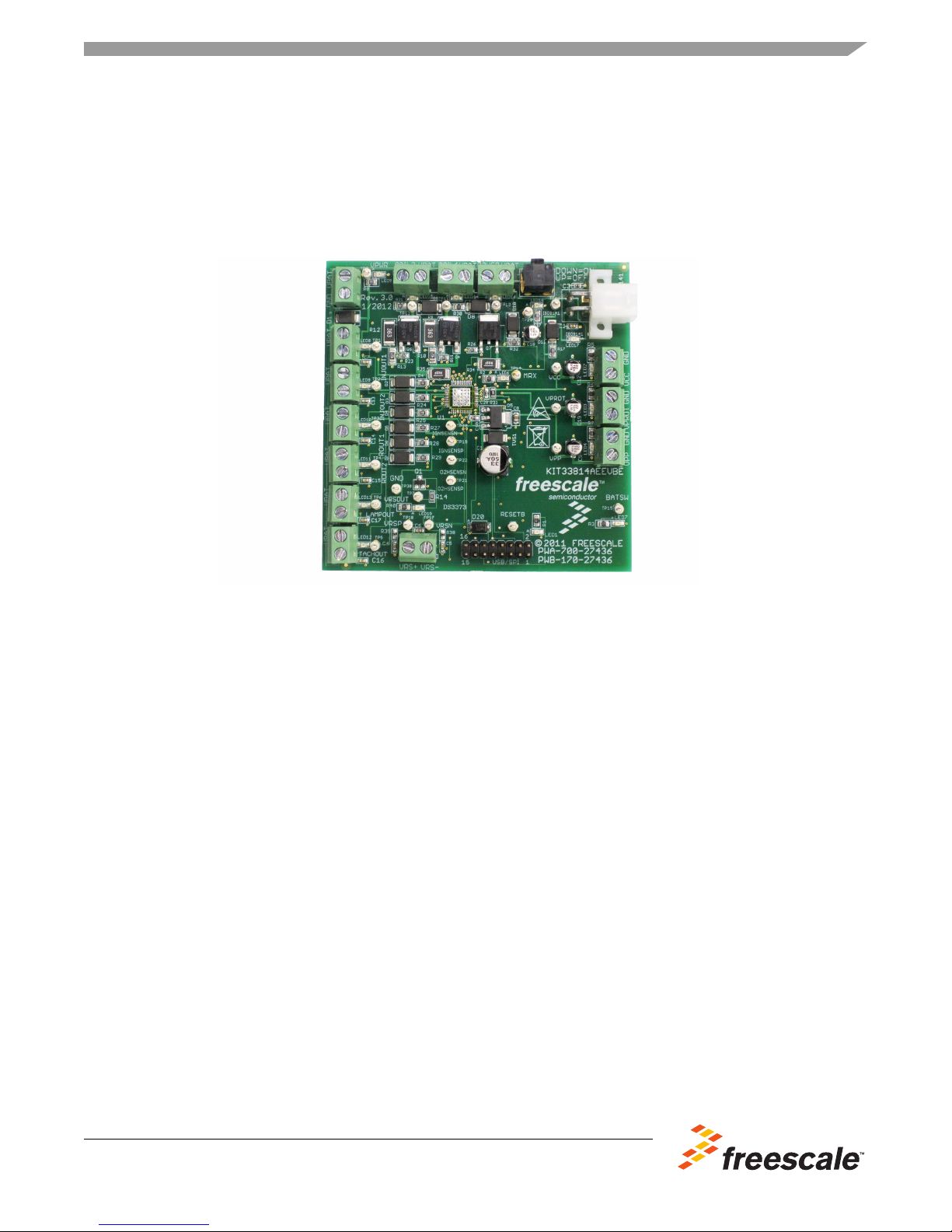
KIT33814AEEVBE Evaluation Board
Featuring the MC33814 Two Cylinder Small Engine Control IC
Rev. 2.0, 4/2013
Figure 1. KIT33814AEEVBE Evaluation Board
Table of Contents
1 Kit Contents / Packing List . . . . . . . . . . . . . . . . . . . . . . . . . . . . . . . . . . . . . . . . . . . . . . . . . . . . . . . . . . . . 2
2 Jump Start . . . . . . . . . . . . . . . . . . . . . . . . . . . . . . . . . . . . . . . . . . . . . . . . . . . . . . . . . . . . . . . . . . . . . . . . . 2
3 Important Notice . . . . . . . . . . . . . . . . . . . . . . . . . . . . . . . . . . . . . . . . . . . . . . . . . . . . . . . . . . . . . . . . . . . . 3
4 Introduction . . . . . . . . . . . . . . . . . . . . . . . . . . . . . . . . . . . . . . . . . . . . . . . . . . . . . . . . . . . . . . . . . . . . . . . . 4
5 Evaluation Board Features . . . . . . . . . . . . . . . . . . . . . . . . . . . . . . . . . . . . . . . . . . . . . . . . . . . . . . . . . . . . 4
6 MC33814 Device Features . . . . . . . . . . . . . . . . . . . . . . . . . . . . . . . . . . . . . . . . . . . . . . . . . . . . . . . . . . . . 4
7 Required Equipment . . . . . . . . . . . . . . . . . . . . . . . . . . . . . . . . . . . . . . . . . . . . . . . . . . . . . . . . . . . . . . . . . 5
8 Evaluation Board Configuration. . . . . . . . . . . . . . . . . . . . . . . . . . . . . . . . . . . . . . . . . . . . . . . . . . . . . . . . . 6
9 Installing SPIGen Freeware on your Computer. . . . . . . . . . . . . . . . . . . . . . . . . . . . . . . . . . . . . . . . . . . . . 7
10 Setup and Using the Hardware . . . . . . . . . . . . . . . . . . . . . . . . . . . . . . . . . . . . . . . . . . . . . . . . . . . . . . . . 8
11 Evaluation Board Hardware Description . . . . . . . . . . . . . . . . . . . . . . . . . . . . . . . . . . . . . . . . . . . . . . . . 10
12 Accessory Board . . . . . . . . . . . . . . . . . . . . . . . . . . . . . . . . . . . . . . . . . . . . . . . . . . . . . . . . . . . . . . . . . . 17
13 Schematic . . . . . . . . . . . . . . . . . . . . . . . . . . . . . . . . . . . . . . . . . . . . . . . . . . . . . . . . . . . . . . . . . . . . . . . 18
14 Board Layout . . . . . . . . . . . . . . . . . . . . . . . . . . . . . . . . . . . . . . . . . . . . . . . . . . . . . . . . . . . . . . . . . . . . . 20
15 Bill of Material . . . . . . . . . . . . . . . . . . . . . . . . . . . . . . . . . . . . . . . . . . . . . . . . . . . . . . . . . . . . . . . . . . . . 26
16 References . . . . . . . . . . . . . . . . . . . . . . . . . . . . . . . . . . . . . . . . . . . . . . . . . . . . . . . . . . . . . . . . . . . . . . 28
17 Revision History . . . . . . . . . . . . . . . . . . . . . . . . . . . . . . . . . . . . . . . . . . . . . . . . . . . . . . . . . . . . . . . . . . 29
© Freescale Semiconductor, Inc., 2013. All rights reserved.
Page 2

Kit Contents / Packing List
Jump Start Your Design
1 Kit Contents / Packing List
• Assembled and tested evaluation board/module in anti-static bag.
• Warranty card
2Jump Start
•Go to www.freescale.com/analogtools
• Locate your kit
• Review your Tool Summary Page
• Look for
• Download documents, software and other information
2 Freescale Semiconductor
KT33814UG User’s Guide Rev. 2.0 4/2013
Page 3

3 Important Notice
Freescale provides the enclosed product(s) under the following conditions:
This evaluation kit is intended for use of ENGINEERING DEVELOPMENT OR EVALUATION
PURPOSES ONLY. It is provided as a sample IC pre-soldered to a printed circuit board to make it easier
to access inputs, outputs, and supply terminals. This EVB may be used with any development system or
other source of I/O signals by simply connecting it to the host MCU or computer board via off-the-shelf
cables. This EVB is not a Reference Design and is not intended to represent a final design
recommendation for any particular application. Final device in an application will be heavily dependent
on proper printed circuit board layout and heat sinking design as well as attention to supply filtering,
transient suppression, and I/O signal quality.
The goods provided may not be complete in terms of required design, marketing, and or manufacturing
related protective considerations, including product safety measures typically found in the end product
incorporating the goods. Due to the open construction of the product, it is the user's responsibility to take
any and all appropriate precautions with regard to electrostatic discharge. In order to minimize risks
associated with the customers applications, adequate design and operating safeguards must be provided
by the customer to minimize inherent or procedural hazards. For any safety concerns, contact Freescale
sales and technical support services.
Should this evaluation kit not meet the specifications indicated in the kit, it may be returned within 30 days
from the date of delivery and will be replaced by a new kit.
Important Notice
Freescale reserves the right to make changes without further notice to any products herein. Freescale
makes no warranty, representation or guarantee regarding the suitability of its products for any particular
purpose, nor does Freescale assume any liability arising out of the application or use of any product or
circuit, and specifically disclaims any and all liability, including without limitation consequential or
incidental damages. “Typical” parameters can and do vary in different applications and actual
performance may vary over time. All operating parameters, including “Typical”, must be validated for each
customer application by customer’s technical experts.
Freescale does not convey any license under its patent rights nor the rights of others. Freescale products
are not designed, intended, or authorized for use as components in systems intended for surgical implant
into the body, or other applications intended to support or sustain life, or for any other application in which
the failure of the Freescale product could create a situation where personal injury or death may occur.
Should the buyer purchase or use Freescale products for any such unintended or unauthorized
application, the buyer shall indemnify and hold Freescale and its officers, employees, subsidiaries,
affiliates, and distributors harmless against all claims, costs, damages, and expenses, and reasonable
attorney fees arising out of, directly or indirectly, any claim of personal injury or death associated with
such unintended or unauthorized use, even if such claim alleges that Freescale was negligent regarding
the design or manufacture of the part. Freescale™ and the Freescale logo are trademarks of Freescale
Semiconductor, Inc. All other product or service names are the property of their respective owners.
© Freescale Semiconductor, Inc. 2013.
Freescale Semiconductor 3
KT33814UG User’s Guide Rev. 2.0 4/2013
Page 4

Introduction
4 Introduction
The KIT33814AEEVBE Evaluation Board is an easy-to-use circuit board that allows the user to exercise
all the functions of the MC33814 two cylinder small engine control IC. A PC communicates to the EVB
through a USB/SPI Dongle (KITUSBSPIDGLEVME) connected to the PC’s USB port. The Freescale
SPIGen (version 7.0) program provides the user interface to the MC33814 SPI port and allows the user
to send commands to the IC and receive status from the IC.
5 Evaluation Board Features
This evaluation board consists of a MC33814 two cylinder small engine control IC, a USB to SPI Dongle
interface, and power conditioning circuitry. All +5.0 V V
the MC33814 built-in power regulator. A +12
voltage regulators.
V V
BAT
6 MC33814 Device Features
power required by the board is obtained from
CC
supply provides the power to the three internal
The MC33814 is an engine control analog power IC intended for two cylinder motorcycle and other small
engine control applications. The IC supports the following functionality:
• Operates over supply voltage range of 4.5 V ≤ VPWR ≤ 36 V
• Logic stability guaranteed down to 2.5 V
• Two fuel injector drivers - typical of 1.3 A each
• Two Ignition IGBT or general purpose gate pre-drivers
• One O2 sensor (HEGO) heater general purpose gate pre-driver
• Relay 1 driver, typically 2.0 A, can be used for fuel pump control
• Relay 2 driver, typically 1.0 A, can be used as power relay control
• Lamp driver, typically 1.0 A can also be used to drive an LED
•V
• MCU reset generator - system integrity monitor (watchdog)
• VPP pre-regulator provides power for VCC and V
• Independent fault protection with all faults reported via the SPI
• ISO 9141 K-line interface for communicating diagnostic messages
• Start-up/shut-down control and power sequence logic
• Interfaces directly to MCU using a 5.0 V SPI and logic I/O
• Differential/single-ended VRS conditioning circuit
Freescale analog ICs are manufactured using the SMARTMOS process, a combinational BiCMOS
manufacturing flow that integrates precision analog, power functions and dense CMOS logic together on a
single cost-effective die.
protected sensor supply tracks VCC +5.0 V regulator
PROT
PROT
regulators
4 Freescale Semiconductor
KT33814UG User’s Guide Rev. 2.0 4/2013
Page 5

7 Required Equipment
Minimum equipment required:
• Power supply 12 V with current limit set initially to 1.0 A
• Oscilloscope (4 channel preferably) with current probe
• Multimeter
• USB-enabled PC with Windows XP or higher
• SPIGen 7.0 or greater
• USB/SPI Dongle board (KITUSBSPIDGLEVME) plus 16-Pin Ribbon Cable
• Typical loads (DC servo motor, fuel injectors, solenoids, lamps, relays and tachometer)
Required Equipment
Freescale Semiconductor 5
KT33814UG User’s Guide Rev. 2.0 4/2013
Page 6
Evaluation Board Configuration
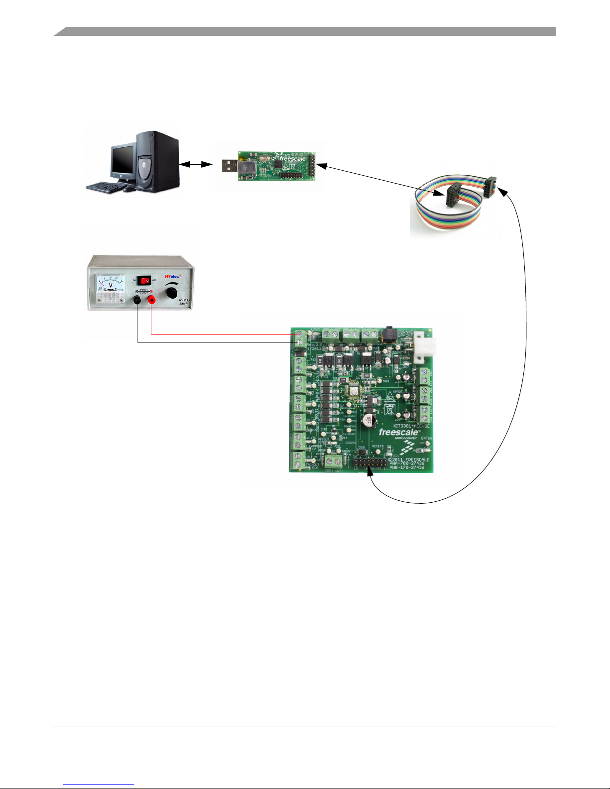
USB/SPI Dongle
(KITUSBSPIDGLEVME)
16-Pin SPI Ribbon
Cable
Power Supply
Two Cylinder Small Engine Control
(KIT33814AEEVBE)
V
BAT
GND
8 Evaluation Board Configuration
Figure 2. KIT33814AEEVBE plus KITUSBSPIDGLEVME Board Setup
6 Freescale Semiconductor
KT33814UG User’s Guide Rev. 2.0 4/2013
Page 7
Installing SPIGen Freeware on your Computer
9 Installing SPIGen Freeware on your Computer
The latest version of SPIGen is designed to run on any Windows 8, Windows 7, Vista or XP-based operating
system. To install the software, go to
open the corresponding Tool Summary Page. Look for “Jump Start Your Design”. Download to your
computer desktop the SPIGen software as well as the associated configuration file.
Run the install program from the desktop. The Installation Wizard will guide you through the rest of the
process.
To use SPIGen, go to the Windows Start menu, then Programs, then SPIGen, and click on the SPIGen icon.
The SPIGen Graphic User Interface (GUI) will appear. Go to the file menu in the upper left hand corner of
the GUI, and select “Open”. In the file selection window that appears, set the “Files of type: ” drop-down
menu to “SPIGen Files (*.spi)”. (As an exceptional case, the file name may have a .txt extension, in which
case you should set the menu to “All Files (*.*)”.) Next, browse for the configuration file you saved on your
desktop earlier and select it. Click “Open”, and SPIGen will create a specially configured SPI command
generator for your evaluation board.
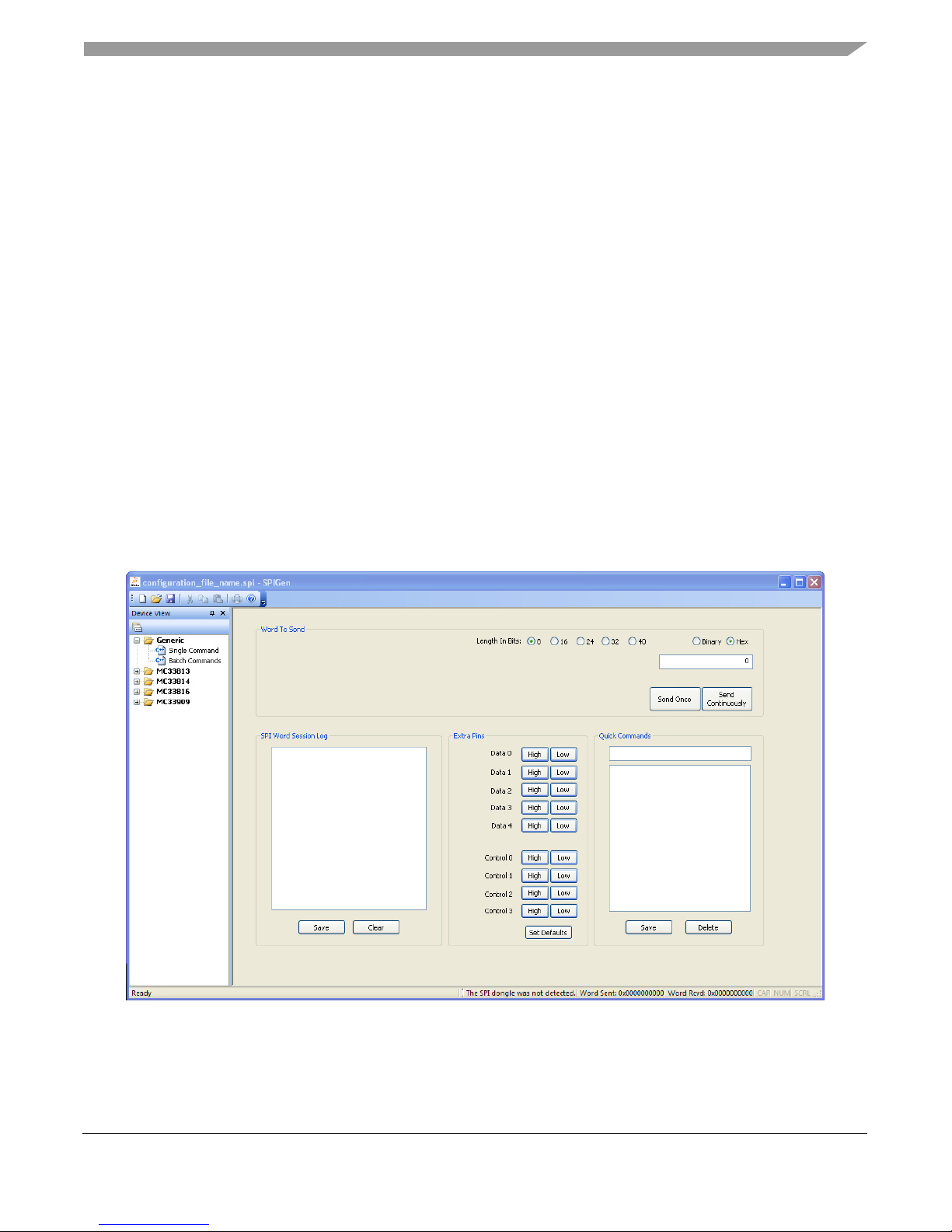
The GUI is shown in Figure 3. The text at the top is the name of the configuration file loaded. The left side
panel displays folders that group user interfaces. The interfaces in the pre-installed MC33814 folder pertain
specifically to the board under discussion.The process of loading the configuration file has assigned a list
of “Extra Pins” as well as a list “Quick Commands”, all of which are board-specific.
www.freescale.com/analogtools and select your kit. Click on that link to
Freescale Semiconductor 7
Figure 3. SPIGen GUI
KT33814UG User’s Guide Rev. 2.0 4/2013
Page 8

Setup and Using the Hardware
10 Setup and Using the Hardware
To perform the examples included in the software bundle, the following connections and setup must be
performed:
1. Make sure the SPIGen program is installed on the PC and can communicate with the USB/SPI dongle as
described in that kit’s documentation.
2. Connect the USB/SPI dongle to the MC33814 EVB via a 16 pin ribbon cable. Make sure to orient the cable so
that pin1 on both the USB/SPI dongle and the MC33814 EVB are connected correctly, pin 1 to pin 1.
3. Connect the USB/SPI dongle to a PC, LED 2 on the USB/SPI Dongle and the USB ON LED on the MC33814
board should both be illuminated.
4. Attach a +12 VDC supply (do not turn on power yet) to the VBAT input connector on the MC33814 EVB, making
sure to observe the GND and +12 V terminals. The current capability of the +12 V supply should exceed the
maximum total current that the number of simultaneously ON loads will require.
5. Attach loads to the COIL1, COIL2, O2HFB, INJOUT1, INJOUT2, ROUT1, ROUT2, LAMPOUT, TACHOUT, and
ISO9141 output terminals as desired.
6. Launch SPIGen and from the “File” menu, select “Open”, and browse to the location of the “KIT33814SW.spi”
file.
7. Turn on the +12 volt supply and set the KEYSW slide switch to the DOWN position. Verify that all is working
correctly, by observing the VPWR, VPP, VCC, and VPROT LEDs, which should all be illuminated. Click on the
“Extra Pins” button in the SPIGen main screen, then click on the following buttons:
8. Click on the INJIN1 “High” button. The INJECTOR 1 load, INJOUT1, and LED should turn on. Clicking on the
INJIN1 “Low” button should turn off the load and LED.
9. Click on the INJIN2 “High” button. The INJECTOR 2 load, INJOUT2 and LED should turn on. Clicking on the
INJIN2 “Low” button should turn off the load and LED.
10. Click on the RIN1 “High” button. The RELAY 1 load, ROUT1 and LED should turn on. Clicking on the RIN1
“Low” button should turn off the RELAY 1 load, ROUT1 and LED.
11. Click on the RIN2 “High” button. The RELAY 2 load, ROUT2, and LED should turn on. Clicking on the RIN2
“Low” button should turn off the RELAY 2 load, ROUT2 and LED.
12. Click on the IGNIN1 “High” button. The COIL1 load and LED should turn on. Clicking on the IGNIN1 “Low”
button should turn off the COIL1 load and LED.
13. Click on the IGNIN2 “High” button. The COIL2 load and LED should turn on. Clicking on the IGNIN1 “Low”
button should turn off the COIL2 load and LED.
14. Click on the O2HIN “High” button. The O2 Heater, O2HFB load and LED should turn on. Clicking on the O2HIN
“Low” button should turn off the O2HFB load and LED.
15. Click on the Data 3 “High” button. The LAMP load and LED should turn on. Clicking on the DATA 3 “Low” button
should turn off the LAMP load and LED.
16. Click on the Data 4 “High” button. The ISO9141 load should turn on. Clicking on the DATA 3 “Low” button
should turn off the ISO9141 load.
If everything described so far occurs then you are ready to proceed with the remaining examples.
8 Freescale Semiconductor
KT33814UG User’s Guide Rev. 2.0 4/2013
Page 9

10.1 Example 1: Running the example batch files
1. Click on the “Batch Commands” Tab in the SPIGen main screen.
2. In the box below the “Commands to Send:” column is a pull-down menu box containing several batch file names.
One of these example batch files is labeled “TOGGLE ALL OUTPUTS”.
3. Click on this label to load it. You should see a list of commands in the “Command to Send” box.
4. Click on the “Continuous” button and observe that the loads and LEDs attached to the MC33814 EVB board
are blinking on and then going out in succession.
There are other demo batch examples that can be run and examined for learning how to use the EVB.
Setup and Using the Hardware
Freescale Semiconductor 9
KT33814UG User’s Guide Rev. 2.0 4/2013
Page 10

Evaluation Board Hardware Description
COIL1
DATA4
DATA3
DATA2
DATA1
CNTL0
VBAT
Reverse Battery
and Transient
Protection
VPWR
+
-
VPWR
LED
VBAT
VBAT
VBAT
LAMPOUT
INJOUT1
ROUT1
IGBT and
Feedback
divider
IGNOUT1 LED
LAMP LED
INJOUT1 LED
ROUT1 LED
OUTPUTS
VPP PASS
TRANSISTOR
VPP
LED
USB/SPI Dongle
Connector
ISO 9141
CONNECTOR
RESETB
RESETB
MRX
BATSW LED
VRSOUT
INJOUT1
LAMPOUT
ROUT1
IGNOUT1
IGNFB1
VPP
(+6.5V)
VPWR
ISO9141
VPPSENS
VPPREF
MTX
IGNIN1
IGNIN2
INJIN1
DATA0
USB ON LED
VPWR
MC33814
GND
1
2
15
16
13
24
7
43
41
13
30
33
32
34
35
15
22
40
29
44
14
18
12V
VCC
LED
VPROT
LED
VCC
(+5V)
GND
GND
VPROT
(+5V)
VBAT
IGBT and
Feedback
divider
IGNOUT2
IGNFB2
COIL2
ROUT2
23
ROUT2
GND
VCC
VPROT
ROUT2 LED
VBAT
VBAT
VPWR
MOSFET
O2HOUT LED
O2HOUT
O2HFB
IGNOUT2 LED
O2HOUT
VBAT
TACHOUT
TACHOUT
TACH LED
IGNSENSE
O2HSENSE
VBAT
INJOUT2 LED
INJOUT2
39
INJOUT2
EXPOSED PAD
GND
VPWR
KEYSW
OFF
ON
MRX LED
BATSW BATSW
FILTER
VRSP
VRSN
MRX
27
VRSOUT LED
VRS IN
11
1
2
5, 6
45
3, 4
46
47
48
VRSOUT
SUPPLIES
INPUTS
21
26
19
EP
9
8
37
17
20
42
CNTL2
CNTL1
4
RIN1
6
8
10
12
14
36
28
O2HIN
RIN2
`
CSB
10
SPI CSB
3
SPI SO
SO
16
5
SI
SPI SI
SPI SCLK
SCLK
7
12
31
INJIN2
N.C.
CNTL3
9
11
13
RGND2
RGND1
INJGND1
38
INJGND2
KEYSWITCH
KEYSW LED
ISO9141 LED
11 Evaluation Board Hardware Description
This EVB consists of a MC33814 Small Engine Control Integrated Circuit (IC), a USB to SPI Dongle
interface, and power conditioning circuitry. All +5 volt VCC power required by the EVB is obtained from
the MC33813 built-in power regulator. A +12V VBAT supply provides the power to the three internal
voltage regulators.
Figure 4. MC33814 EVB Block Diagram
KT33814UG User’s Guide Rev. 2.0 4/2013
10 Freescale Semiconductor
Page 11

11.1 LED Display
Nineteen LED’s are provided as visual output devices for the MC33814 EVB board. A list of the LED
devices is shown below:
1. VPWR LED - Indicates when a +12 volt supply is connected to the EVB.
2. VPP LED - Indicates that the VPP Pre-regulator is supplying +6.5 volts to the two +5.0 volt regulators, VCC and
VPROT.
3. VCC LED - Indicates that the MC33814 internal +5.0 volt regulator is running and providing the +5.0 volt VCC
voltage supply.
4. VPROT LED - Indicates that the VPROT +5.0 volt regulator is turned on and is supplying 5.0 V.
5. KEYSW LED - Indicates when the Keyswitch is turned on supplying +12 V to the KEYSW input.
6. IGNOUT1 LED - Indicates that the Ignition input, IGNIN1 or SPI bit is active, and the Ignition 1 output driver is
turned on.
7. IGNOUT2 LED - Indicates that the Ignition input, IGNIN2 or SPI bit is active, and the Ignition 2 output driver is
turned on.
8. O2HOUT LED - Indicates that the O2HIN input, or the SPI bit is active, and the O2 Heater Driver output driver is
turned on.
Evaluation Board Hardware Description
9. INJOUT1 LED - Indicates that the Injector 1 input, INJIN1 or SPI bit is active, and the Injector 1 output is pulled
low.
10. INJOUT2 LED - Indicates that the Injector 2 input, INJIN2 or SPI bit is active, and the Injector 2 output is pulled
low.
11. ROUT1 LED - Indicates that the Relay 1 input RIN1, or SPI bit is active, and the Relay 1 output is pulled low.
12. ROUT2 LED - Indicates that the Relay 2 input RIN2, or SPI bit is active, and the Relay 2 output is pulled low.
13. LAMPOUT LED - Indicates that the Lamp SPI control bit is active and the LAMPOUT pin is pulled low.
14. VRSOUT LED - Indicates that there is activity on the VRSN and VRSP pins, and that the VRS circuit has
detected a valid VRS signal.
15. TACHOUT LED - Indicates the state of the TACHOUT output signal.
16. MRX LED - Indicates the state of the MRX line as a result of the data on the ISO9141 line.
17. BATSW LED - Indicates the state of the on-board Key Switch. When the Key Switch is ON the BATSW LED is
ON.
18. USB LED - Indicates that the USB SPI dongle is connected properly and is attached to an active USB port on a
PC.
19. ISO9141 LED - Indicates the state of the ISO9141 line. When this LED is ON, the ISO9141 line is LOW and
when the LED is OFF, the ISO9141 line is HIGH.
11.2 Test Point Definitions
The EVB contains twenty five (25) test point jumpers that provide access to certain signals in the
MC33814 as follows:
1. VPWR - 12 volts (VBAT minus Schottky diode drop)
2. GND - 0.0 volts
Freescale Semiconductor 11
KT33814UG User’s Guide Rev. 2.0 4/2013
Page 12

Evaluation Board Hardware Description
3. VPP - 6.5 volts
4. VCC - 5.0 volts
5. VPROT - 5.0 volts
6. BATSW - 0 or 5.0 volts depending on the state of KEYSW
7. KEYSW - 0 or 12 volts depending on the state of KEYSW
8. ISO9141 - 0 or 12 volts depending on the state of MTX
9. MRX - 0 or 5.0 volts depending on the state of ISO9141 line.
10. VRSOUT - 0 or 5.0 volts depending on the VRSN and VRSP inputs
11. TACHOUT - 0 or 5.0 volts depending on VRSOUT or internal SPI bits.
12. LAMPOUT - 0 or 12 volts depending on the SPI bits
13. ROUT2 - 0 or 12 volts depending on RIN2 or internal SPI bits.
14. ROUT1 - 0 or 12 volts depending on RIN1 or internal SPI bits.
15. INJOUT2 - 0 or 12 volts depending on INJIN2 or internal SPI bits.
16. INJOUT1 - 0 or 12 volts depending on INJIN1 or internal SPI bits.
17. COIL2 - 0 or 12 volts depending on IGNIN2 or internal SPI bits.
18. COIL1 - 0 or 12 volts depending on IGNIN1 or internal SPI bits.
19. O2HFB - 0 or 12 volts depending on O2HOUT or internal SPI bits.
20. VRSN - -0.3 to 5.0 volts (clamped internally) from VRS low side.
21. VRSP - -0.3 to 5.0 volts (clamped internally) from VRS high side.
22. O2HSENSN - Ground side of O2H driver current sense resistor (0.02 ohms)
23. O2HSENSP - High side of O2H driver current sense resistor (0.02 ohms)
24. IGNSENSN - Ground side of IGN1/2 driver current sense resistor (0.02 ohms)
25. IGNSENSP - High side of IGN1/2 driver current sense resistor (0.02 ohms)
11.3 Input Signal Definitions
The MC33814 has nine logic level input signals that are used to control certain outputs or functions inside
the circuit. These nine signals are:
1. O2HIN - Controls the O2 Heater Pre-Driver output
2. IGNIN1 - Controls the Ignition 1 Pre-Driver output
3. IGNIN2 - Controls the Ignition 2 Pre-Driver output
4. INJIN1 - Controls the state of the INJOUT1 output
5. INJIN2 - Controls the state of the INJOUT2 output
6. RIN1 - Controls the state of the ROUT1 output
7. RIN2 - Controls the state of the ROUT2 output
12 Freescale Semiconductor
KT33814UG User’s Guide Rev. 2.0 4/2013
Page 13

Evaluation Board Hardware Description
8. MTX - Provides the transmit data to the ISO9141 line
9. RESETB - When the RESETB line is held low, the MC33814 inhibits the internal watchdog reset.
These nine signals are provided by the nine parallel outputs from the USB/SPI interface as described
below:
1. O2HIN- Connected to the DATA4 signal
2. IGNIN1 - Connected to the DATA2 signal
3. IGNIN2 - Connected to the DATA3 signal
4. INJIN1 - Connected to the DATA0 signal
5. INJIN2 - Connected to the DATA1 signal
6. RIN1 - Connected to the CNTL1 signal
7. RIN2 - Connected to the CNTL0 signal
8. MTX - Connected to the CNTL2 signal
9. RESETB - Connected to the CNTL3 signal
The DATA0 -DATA4 and CNTL0-CNTL3 signals are logic level outputs from the USB/SPI dongle,
controllable directly from the SPIGen program. An example SPIGEN configuration file called
“KIT33814SW.spi” is provided in the software bundle which contains several batch file examples.
If the user prefers to supply the various MC33814 input signals externally, other than from the USB-SPI
Interface, the connections are available on the connector listed below.
Freescale Semiconductor 13
KT33814UG User’s Guide Rev. 2.0 4/2013
Page 14

Evaluation Board Hardware Description
11.4 USB/SPI Dongle Connector
The USB/SPI dongle connector is a 16-pin, 0.1” center, dual-row connector designed to interface directly
to the USB/SPI dongle unit (KITUSBSPIDGLEVME). This connector mates with the 16-conductor flat
cable that connects to the USB/SPI dongle .The USB/SPI dongle connector consists of the following 16
pins.
Table 1. USB/SPI Dongle Pin Description
Pin
Number
1 CSB SPI signal, Chip Select Bar
2 CNTL2 CNTL2 connected to MTX
3 SO SPI signal, Serial Out
4 CNTL1 CNTL1 connected to RIN1
5 SI SPI signal, Serial In
6 CNTL0 CNTL0 connected to RIN2
7 SCLK SPI signal, Serial Clock
8 DATA4 DATA4 connected to O2HIN
9 CNTL3 CNTL3 connected to RESETB
10 DATA3 DATA3 connected to IGNIN2
11 VDD +5.0 Volt VDD from USB
12 DATA2 DATA2 connected to IGNIN1
13 +3.3 V +3.3 V from USB (Not Used)
14 DATA1 DATA1 connected to INJIN2
15 GND Signal Ground
16 DATA0 DATA0 connected to INJIN1
Name Description
14 Freescale Semiconductor
KT33814UG User’s Guide Rev. 2.0 4/2013
Page 15

11.5 Screw Terminal Connections
VBAT Input
VRS Input
+5.0 V VCC
+5.0 V VPROT
+5.0 V VPP
INJOUT1
INJOUT2
ROUT1
ROUT2
LAMPOUT
TACHOUT
USB/SPI Dongle Input
COIL1
COIL2 O2HFB
ISO9141
The MC33814 board contains twelve output and two input screw terminal connections and one 4 pin I/O
connector to allow easy access to the MC33814’s circuits.
Evaluation Board Hardware Description
Figure
6 shows the locations of the screw terminals and their functional definitions.
Figure 5. Connector Designations
KT33814UG User’s Guide Rev. 2.0 4/2013
Freescale Semiconductor 15
Page 16

Evaluation Board Hardware Description
11.6 Evaluation Board Connectors
11.6.1 Input Connectors
There are two Input connectors and one input/output connector.
1. (VBAT) +12 VOLT POWER SUPPLY INPUT -
Screw Terminal 1 - Ground (-12 V)
Screw Terminal 2 - VBAT (+12 V)
2. (VRS) VARIABLE RELUCTANCE SENSOR INPUT -
Screw Terminal 1 - VRS- (Low Side)
Screw Terminal 2 - VRS+ (High Side)
3. (ISO9141) 4 PIN INPUT/OUTPUT -
Terminal 1 - Ground
Terminal 2 - N.C.
Terminal 3 - VPWR
Terminal 4- ISO9141 bidirectional signal.
11.6.2 Output Connectors
There are twelve output connectors which are two position screw terminals that provides the following
signals:
1. (COIL 1) IGNITION OUTPUT 1 -
Screw Terminal 1 - Low side drive, IGNOUT1 (IGBT collector)
Screw Terminal 2 - VBAT
2. (COIL 2) IGNITION OUTPUT 2 -
Screw Terminal 1 - Low side drive, IGNOUT2 (IGBT collector)
Screw Terminal 2 - VBAT
3. (O2HFB) O2 Heater OUTPUT -
Screw Terminal 1 - Low side drive, O2HOUT (MOSFET drain)
Screw Terminal 2 - VBAT
4. (INJOUT1) INJECTOR OUTPUT 1 -
Screw Terminal 1 - Low side drive, INJOUT1
Screw Terminal 2 - VBAT
5. (INJOUT2) INJECTOR OUTPUT 2 -
Screw Terminal 1 - Low side drive, INJOUT2
Screw Terminal 2 - VBAT
6. (ROUT1) RELAY OUTPUT 1 -
Screw Terminal 1 - Low side drive, ROUT1
Screw Terminal 2 - VBAT
7. (ROUT2) RELAY OUTPUT 2 -
Screw Terminal 1 - Low side drive, ROUT2
Screw Terminal 2 - VBAT
16 Freescale Semiconductor
KT33814UG User’s Guide Rev. 2.0 4/2013
Page 17

8. (LAMPOUT) LAMP DRIVER OUTPUT 2 -
Screw Terminal 1 - Low side drive, LAMPOUT
Screw Terminal 2 - VBAT
9. (TACHOUT) TACHOMETER DRIVER OUTPUT 2 -
Screw Terminal 1 - Low side drive, TACHOUT
Screw Terminal 2 - VBAT
10. (VPP) +6.5 VOLT REGULATOR OUTPUT -
Screw Terminal 1 - VPP OUTPUT
Screw Terminal 2 - GND
11. (VCC) +5 VOLT REGULATOR OUTPUT -
Screw Terminal 1 - VCC OUTPUT
Screw Terminal 2 - GND
12. (VPROT) PROTECTED +5 VOLT REGULATOR OUTPUT -
Screw Terminal 1 - VPROT OUTPUT
Screw Terminal 2 - GND
12 Accessory Board
Accessory Board
This kit may be used with Freescale's one of the following kits:
The KITUSBSPIDGLEVME Evaluation board (shown below) provides a USB to SPI interface that
features the MC68HC908JW32 with Dongle. It is a working hardware/software example that allows a user
to become familiar with the MC68HC908JW32 microcontroller by means of an actual useful application,
a USB to SPI and USB to parallel converter. The main function provided by this kit is to allow a PC, that
may not have a parallel port, to communicate with other Freescale Evaluation Kits, via a USB port. The
USB port is a standard feature on almost every new PC. This kit makes use of the MC68HC908JW32’s
built-in USB, SPI and parallel ports.
Figure 6. KITUSBSPIDGLEVME Evaluation Kit
Freescale Semiconductor 17
KT33814UG User’s Guide Rev. 2.0 4/2013
Page 18

Schematic
13 Schematic
Figure 7. Evaluation Board Schematic, Part 1
18 Freescale Semiconductor
KT33814UG User’s Guide Rev. 2.0 4/2013
Page 19

Schematic
Figure 8. Evaluation Board Schematic, Part 2
KT33814UG User’s Guide Rev. 2.0 4/2013
Freescale Semiconductor 19
Page 20

Board Layout
14 Board Layout
14.1 Assembly Layer Top
20 Freescale Semiconductor
KT33814UG User’s Guide Rev. 2.0 4/2013
Page 21

14.2 Assembly Layer Bottom
Note: For convenience when viewing the actual board, this image has been flipped horizontally with respect to the other layer
images in this document.
Board Layout
KT33814UG User’s Guide Rev. 2.0 4/2013
Freescale Semiconductor 21
Page 22

Board Layout
14.3 Top Layer Routing
22 Freescale Semiconductor
KT33814UG User’s Guide Rev. 2.0 4/2013
Page 23

14.4 Inner Layer 1 Routing
Board Layout
Freescale Semiconductor 23
KT33814UG User’s Guide Rev. 2.0 4/2013
Page 24

Board Layout
14.5 Inner Layer 2 Routing
24 Freescale Semiconductor
KT33814UG User’s Guide Rev. 2.0 4/2013
Page 25

14.6 Bottom Layer Routing
Board Layout
Freescale Semiconductor 25
KT33814UG User’s Guide Rev. 2.0 4/2013
Page 26

Bill of Material
15 Bill of Material
Item Qty Schematic Label Value Description Package
1 2 C1, C11 33 μF/50V CAP ALUM 33UF 50V 20% PANASONIC_E
2 2 C2, C7 0.01 μF CAP CER 10000PF 100V X7S C0402
3 2 C3, C10 0.1 μF CAP CER 0.1UF 25V Y5V C0402
4 1 C6 0.001 μF CAP CER 1000PF 100V 10% X7R C0402
51C8 1 μF CAP CER 1UF 16V Y5V C0805
6 3 C9, C18, C19 22 μF/16V CAP ALUM 22UF 16V 20% PANASONIC_B
8 1 C20 100 pF CAP CER 100PF 50V 5% NP0 C0402
9 1 D1 S35B-LTP DIODE SCHOTTKY 3A 50V SMB
10 10 D2-D11 S1B RECTIFIER GPP 100V 1A SMB
11 1 D20 S1A DIODE SCHOTTKY 30V 1A SMA
12 1 ISO9141 39-29-1048 CONN HEADER 4POS 4.2MM R/A TIN
13 1 KEYSW SW100-ND SWITCH SLIDE SPST 0.5A BLACK G-105-0513
14 19 LED1-LED19 LED LED MINI TOPLED GREEN 529NM SMD
17 1 Q1 2N7002 MOSFET N-CH 60V 115MA SOT23
18 2 Q4, Q6 ISL9V2040D3ST IGBT 440V 20A 125W DPAK
19 1 Q5 FZT789A TRANS PNP -25V -3000MA SOT223
20 1 Q7 BUK9230-100B MOSFET N-CH 100V 47A D-PAK
21 6 R1-R3, R5, R6, R40 470 RES 470 OHM 1/8W 5% M0805
22 13 R4, R8, R14, R17,
R24, R25, R27-R32,
R37
23 1 R7 680 RES 680 OHM 1/8W 5% M0805
24 2 R9, R12 36.0K RES 36K OHM 1W 5% R2512
25 2 R10, R13 4.02K RES 4.02K OHM 1/4W 1% R1206
26 3 R11, R23, R26 16K RES 16K OHM 1/10W 5% R0603
28 1 R33 10K RES 10K OHM 1/8W 5% 0805 R0603
29 2 R34, R35 0.02 RES 0.02 OHM 1/2W 1% R2010
1K RES 1K OHM 1/8W 5% M0805
30 2 R38, R39 15K RES 15K OHM 1/10W 5% 0402 SMD R0603
26 Freescale Semiconductor
KT33814UG User’s Guide Rev. 2.0 4/2013
Page 27

Bill of Material
Item Qty Schematic Label Value Description Package
31 24 RESETB, TP1-TP7,
MA01-1 TERM PC TEST POINT LOOP 0.020" BR
TP9,TP11-TP22,
TP29, TP30, VCC,
VPP, VPROT
32 1 TVS1 SMBJ40 DIODE TVS 40V 600W UNIDIR 5% SMB DO214AA
33 1 U1 MC33814AE Two Cylinder Small Engine Control IC 48-PIN LQFP-EP
34 1 USB/SPI Header CONN HEADER VERT 0.100 16POS
15AU
35 14 X1-X14 Dual screw terminal CONN TERM BLOCK 2POS 5.08MM PCB
Note: Freescale does not assume liability, endorse, or warrant components from external manufacturers that are referenced in circuit drawings
or tables. While Freescale offers component recommendations in this configuration, it is the customer’s responsibility to validate their application.
Freescale Semiconductor 27
KT33814UG User’s Guide Rev. 2.0 4/2013
Page 28

References
16 References
The following table contains URLs where you can obtain information on other Freescale products and
KIT33814AEEVBE product solutions:
Freescale.com Support Pages
MC33814
Product Summary Page
KITUSBSPIDGLEVME
Tool Summary Page
SPIGEN Tool Summary Page www.freescale.com/files/soft_dev_tools/software/device_drivers/SPIGen.html
Automotive Home Page www.freescale.com/automotive
Analog Home Page www.freescale.com/analog
www.freescale.com/webapp/sps/site/prod_summary.jsp?code=MC33814
http://www.freescale.com/webapp/sps/site/
prod_summary.jsp?code=KITUSBSPIDGLEVME
URL
16.1 Support
Visit Freescale.com/support for a list of phone numbers within your region.
16.2 Warranty
Visit Freescale.com/warranty for a list of phone numbers within your region.
28 Freescale Semiconductor
KT33814UG User’s Guide Rev. 2.0 4/2013
Page 29

17 Revision History
REVISION DATE DESCRIPTION OF CHANGES
Revision History
1.0
2.0
4
2/2012 • Initial Release
4/2013
• Add Jump Start link for downloading software and/or documents.
• Update SPIGen section to match latest template
Freescale Semiconductor 29
KT33814UG User’s Guide Rev. 2.0 4/2013
Page 30

How to Reach Us:
Home Page:
freescale.com
Web Support:
freescale.com/support
Information in this document is provided solely to enable system and software
implementers to use Freescale products. There are no express or implied copyright
licenses granted hereunder to design or fabricate any integrated circuits on the
information in this document.
Freescale reserves the right to make changes without further notice to any products
herein. Freescale makes no warranty, representation, or guarantee regarding the
suitability of its products for any particular purpose, nor does Freescale assume any
liability arising out of the application or use of any product or circuit, and specifically
disclaims any and all liability, including without limitation consequential or incidental
damages. “Typical” parameters that may be provided in Freescale data sheets and/or
specifications can and do vary in different applications, and actual performance may
vary over time. All operating parameters, including “typicals,” must be validated for
each customer application by customer’s technical experts. Freescale does not convey
any license under its patent rights nor the rights of others. Freescale sells products
pursuant to standard terms and conditions of sale, which can be found at the following
address: http://www.reg.net/v2/webservices/Freescale/Docs/TermsandConditions.htm
Freescale and the Freescale logo are trademarks of Freescale Semiconductor, Inc.,
Reg. U.S. Pat. & Tm. Off. SMARTMOS is a trademark of Freescale Semiconductor,
Inc. All other product or service names are the property of their respective owners.
© 2013 Freescale Semiconductor, Inc.
Document Number: KT33814UG
Rev. 2.0
4/2013
 Loading...