

Page 1
i.MX31 PDK 1.4
Windows Embedded CE 6.0/
Windows CE 5.0
Quick Start Guide
Page 2

Information in this document is provided solely to enable system and software implementers to use Freescale Semicon-
How to Reach Us:
Home Page:
www.freescale.com
E-mail:
support@freescale.com
USA/Europe or Locations Not Listed:
Freescale Semiconductor
Technical Information Center, CH370
1300 N. Alma School Road
Chandler, Arizona 85224
+1-800-521-6274 or +1-480-768-2130
support@freescale.com
Europe, Middle East, and Africa:
Freescale Halbleiter Deutschland GmbH
Technical Information Center
Schatzbogen 7
81829 Muenchen, Germany
+44 1296 380 456 (English)
+46 8 52200080 (English)
+49 89 92103 559 (German)
+33 1 69 35 48 48 (French)
support@freescale.com
Japa n:
Freescale Semiconductor Japan Ltd.
Headquarte rs
ARCO Tower 15F
1-8-1, Shimo-Meguro, Meguro-ku,
Tokyo 153-0064, Japan
0120 191014 or +81 3 5437 9125
support.japan@freescale.com
Asia/Pacific:
Freescale Semiconductor China Ltd.
Exchange Building 23F
No. 118 Jianguo Road
Chaoyang District
Beijing 100022
China
+86 010 5879 8000
support.asia@freescale.com
For Literature Requests Only:
Freescale Semiconductor Literature Distribution
Center
P.O. Box 5405
Denver, Colorado 80217
1-800-521-6274 or 303-675-2140
Fax: 303-675-2150
LDCForFreescaleSemiconductor@hibbertgroup.com
ductor products. There are no express or implied copyright licenses granted hereunder to design or fabricate any integrated circuits or integrated circuits based on the information in this document.
Freescale Semiconductor reserves the right to make changes without further notice to any products herein. Freescale
Semicond uc tor ma kes no w ar rant y, rep re se nt atio n o r gua ra nt ee re g ardin g the s u itab ility of its pro duc ts for any particular purpose, no r does F reesca le Semico ndu ctor as sum e any li abil ity ar is ing ou t of th e app lica tion or use o f any produ ct
or circuit, and specifically disclaims any and all liability, including without limitation consequential or incidental damages. “Typi cal” parameters that may be provided in Freescal e Semiconductor data sheets a nd/ or specifications can and
do vary in different applications and actual performance may vary over time. All operating parameters, including “Typicals”, must be validated for each c us tomer application by customer’s technical experts. Freescale S emiconductor does
not convey any license under its patent rights nor the rights of others. Freescale Semiconductor products are not designed, intended, or authorized for use as components in systems intended for surgical implant into the body, or other
applicat io ns in tend e d to sup po rt or sustain life, or for any oth er app li cati on in whi c h the fa ilur e of the Free sca le Se mi conductor product could create a situation where personal injury or death may occur. Should Buyer purchase or use
Freescale Semico ndu ctor p r oduct s for any su ch un inte nded o r u naut hor ized app lica tion , Buy er sh all i ndem nif y and ho ld
Freescale Semiconductor and its officers, employees, subsidiaries, affiliates, and distributors harmless against all
claims, costs, damages, and expenses, and reasonable attorney fees arising out of, directly or indirectly, any claim of
personal injury or death as s ociated with suc h unintended or unauthorized use, even if such claim alleges t hat Freescale
Semiconductor was negligent regarding the design or manuf acture of the part.
Federal Communications Commission Radio Frequency Interference Statement
This device complies with Part 15 of the FCC rules. Operation is subject to the following two conditions:
(1) This devi ce ma y not cause harmful interference and
(2) this device must accept any interference received, including interference that might caus e undesired operation.
Changes or mod if ications to thi s equipment not expressly approved by Freescale could void the user’s autho rity to operate the equipment.
Freescale™ and the Freescale logo are trademarks of Freescale Semiconductor, Inc. All ot her produc t or service names
are the property of their respect ive owner s. Microsof t and Windows are registe red trademarks of Microso ft Corporat ion.
RealView is a registered trademark of ARM Limited. ARM11 is the trademark of ARM Limited. The ARM logo is a
registered tra demark of ARM L td. Wi -Fi i s a regis tered t rademark of th e Wi-F i Al liance. Blu etoot h i s a re gi ster ed trad emark of the Bluet ooth SIG, Inc., and is used under lice ns e. Wi-Fi CERTIFIED is a trademark of t he Wi-Fi Alliance.
© Freescale Se m iconductor, Inc. 2007 - 2008. A ll r ights reserved.
Page 3

1 About the Boards 3
About the 3-Stack Platfo rm System . . . . . . . . . . . . . . . . . . . . . . . . . . . . . . . . . . . 3
CPU Board . . . . . . . . . . . . . . . . . . . . . . . . . . . . . . . . . . . . . . . . . . . . . . . . . . . . . . 7
Debug Board. . . . . . . . . . . . . . . . . . . . . . . . . . . . . . . . . . . . . . . . . . . . . . . . . . . . . 8
Personality Board . . . . . . . . . . . . . . . . . . . . . . . . . . . . . . . . . . . . . . . . . . . . . . . . 11
2 Getting Started 13
Unpack the Kit . . . . . . . . . . . . . . . . . . . . . . . . . . . . . . . . . . . . . . . . . . . . . . . . . . 13
CD-ROM Contents . . . . . . . . . . . . . . . . . . . . . . . . . . . . . . . . . . . . . . . . . . . . . . . 15
Provide a Development PC. . . . . . . . . . . . . . . . . . . . . . . . . . . . . . . . . . . . . . . . . 16
3 Build the Platform 17
Build a Development Platform: Assemble Three Boards. . . . . . . . . . . . . . . . . . 17
Connect Personality Board to Debug Board. . . . . . . . . . . . . . . . . . . . . . . . . 18
Connect CPU Board to Debug Board . . . . . . . . . . . . . . . . . . . . . . . . . . . . . .19
Connect Development Platform to PC; Run Preloaded Image. . . . . . . . . . .20
Build a Demo Platform: Assemble Two Boards. . . . . . . . . . . . . . . . . . . . . . . . . 21
Connect CPU Board to Pers onality Board . . . . . . . . . . . . . . . . . . . . . . . . . .22
Connect Power Supply; Run Preloaded Demo . . . . . . . . . . . . . . . . . . . . . . 23
4 Using the Demo Image 25
Multimedia Codecs Content . . . . . . . . . . . . . . . . . . . . . . . . . . . . . . . . . . . . . . . . 25
Touch Pad Calibration Tool . . . . . . . . . . . . . . . . . . . . . . . . . . . . . . . . . . . . . . . . 25
Downloading Multimedia to the 3-Stack Board . . . . . . . . . . . . . . . . . . . . . . . . . 28
Using Active Sync. . . . . . . . . . . . . . . . . . . . . . . . . . . . . . . . . . . . . . . . . . . . . 28
Using an SD Card . . . . . . . . . . . . . . . . . . . . . . . . . . . . . . . . . . . . . . . . . . . . .33
Using a USB Memory Stick . . . . . . . . . . . . . . . . . . . . . . . . . . . . . . . . . . . . . 34
Running the Demo Applications. . . . . . . . . . . . . . . . . . . . . . . . . . . . . . . . . . . . . 34
Running the TV-Out Application . . . . . . . . . . . . . . . . . . . . . . . . . . . . . . . . .35
Running the Rotate Application . . . . . . . . . . . . . . . . . . . . . . . . . . . . . . . . . .43
Changing the Windows CE 5.0 or Windows Embedded CE 6.0 Demo Image
Version . . . . . . . . . . . . . . . . . . . . . . . . . . . . . . . . . . . . . . . . . . . . . . . . . . . 45
Ready to Begin Your Development? . . . . . . . . . . . . . . . . . . . . . . . . . . . . . . . . . 46
i.MX31 PDK 1.4 Quick Start Guide, Rev. 1.4
1
Page 4

i.MX31 PDK Kit Configuration Guide
2
Page 5

About the Boards
This chapter provides detailed information about the three boards (CPU, Debug,
Personal ity) and the locations of the connect ors and switches for each.
CAUTION Your PDK arrives housed in a plastic device enclosure, which under
normal circumstanc es you should not remove. However, the PDK
documentation set includes information for board-level components, and
also explains in some documents how to assemble the boards into th e
enclosu re. Should you need to work dire ctly with the bo ards, please use
great caution in handling the components:
– To remove or work w ith the boards, use sta tic precautions.
– To remove or add the enclosure, firs t read the enclosure assembly instructions
carefully and note which areas are delicate, such as the speakers.
About the 3-Stack Platform System
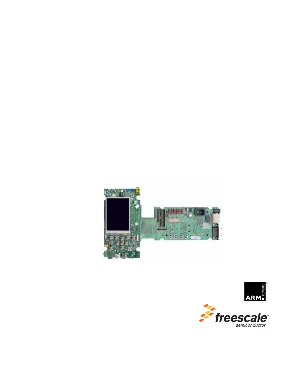
Freescale introduces the 3-Stack Pla tform System, which you use to develop multim edia
and connec tivity applications using the i.MX31 Applications Processor and the MC13783
Audio and Power Management device.
The 3-Stack Platform System decreases the time between first development and final
product release by providing you (as the system designer) with a near-to-final product
design, which you can use as a development platform for software and hardware.
There are two Board Support Packages (BSP) for the 3-Stack Platform System, with one
BSP for Microsoft® Windows CE™ 5.0/Windows Embedded CE™ 6.0, and one BSP for
Linux operat in g syst ems . Th ese BSPs co nt ain dr iv ers op ti mized f or mul timedi a operat i ons
using the i.MX31 and MC13783 devices.
Freescal e's 3-Stack Platform S ystem consists of three small boards: CPU, Debug , and
Personality.
• A CPU board contains the i.MX31 CPU, me m o ries, and the MC13783 Power
Management IC (PMIC).
• A Debug board provides the debug interfaces (such as JTAG), and also has a CPLD
that imple m ents an external Etherne t and serial controller for debug purposes.
• The Personal ity board implements the functionality of the 3-Stack board, and
contains hardware for Wi-Fi connec tivity, FM receiver, and so on. The Personality
board can b e modi fied to meet you r sp ecif ic requi reme nt s wi tho ut the nee d to modi fy
the other two boards (CPU, Debug). The Personality board was desig ned to support
1
i.MX31 PDK 1.4 Quick Start Guide
3
Page 6

About the Boards
About the 3-Stack Platform System
common multimedia applications, and has a 2.8-inch VGA display, im age sensor
camera, Wi-Fi CERTI FIED™ IEEE 802.11™ b/g st andards, FM receiver, SD Card
connector, USB OTG, USB Host, 2.4 QVGA smart display panel connector, ATA
connector and TV-Out connector. As the 3-Stack platform c ontinues t o evolve, more
Personality boards will be created to meet new multimedia requirements. Table 1.2
lists 3-Stack platform features in more detail.
Table 1.1 3-Stack Platform Features
Details
All boards • Near to final product form-factor demonstration
CPU board
Personality board • Peripheral components
Debug board • Two RS-232 interfaces
Expansion Headers • Utilizing reliable high density connector to interface
Battery Support • +4.2 V 2400mAh Battery power supply and Battery
LCD Display • 2.8 inch TFTLCD display panel with touch panel and
Smart LCD Connector • 2.4 inch QVGA smart display panel connector
modules and working platforms.
• Solid reference schematics that closely resemble
final products to aid customers' designs.
• i.MX31 ARM11
• MC13783 Atlas power management chip
• 256 MB of NAND Flash Memory
• 128 MB of 32 bit DDR SDRAM memory
• 37.914 mm x 67.517 mm
• Interface connectors
• 71.428 mm x 129.462 mm
• 10/100 Base-T Ethernet connector
• Current measure connectors
• 71.400 mm x 174.900 mm
between boards, 3 board assembly for software
development and 2-board assembly (without debug
board) for demonstration
Charging Function
LED backlight
™ Applications Processor
Camera Interface • Image sensor camera connector
Selectable Clock
Sources
4
i.MX31 PDK 1.4 Quick Start Guide
• Two selectable system clock sources: 32.768 KHz
and 26 Mhz
Page 7

About the 3-Stack Platform System
Table 1.1 3-Stack Platform Features
Details
About the Boards
Debug Port
Video and Audio
Stereo
GPS Connector • One connector to outboard GPS module
FM Receiver
TV Out • TV decoder that supports 8-bit color, NTSC and PAL
PC Card Expansion • SD card connectors, with card sense
Keypad • Onboard keypad and keypad connector
Network Support • Onboard Wi-Fi CERTIFIEDFter IEEE 802.11 b/g
USB • One USB OTG high-speed transceiver with mini-
ATA Support ATA5 controller with
•RealView
• Stereo microphone jack, headphone and video jack,
stereo and mono (ear piece) speaker terminals
formats
standards and Bluetooth(r) Core Specification
Version 2.0 + EDR (enhanced data rate)
combination module
• One Ethernet jack connector (for application/debug)
USB connector
• One USB high-speed host transceiver, with
standard USB host connector
• One 44-position dual row 2 mm header for small
form-factor disk drivers
• One 40-pin ZIF connector for Toshiba HDD
®-ICE debug support
Accelerometer • Onboard accelerometer with sensitivity in three
Serial Port Two RS-232 interfaces with DB-9 connectors
separate axes (X, Y, Z)
• One RS-232 interface is driven by a UART channel
internal to the MX31, and it supports DCE with
optional full modem controls
• The other RS-232 interface is DTE with optional full
modem controls
i.MX31 PDK 1.4 Quick Start Guide
5
Page 8

About the Boards
About the 3-Stack Platform System
Cables • 5.0V/2.4A universal power supply kit
Software • Sample Windows® embedded CE binary image
Application
Development Tools
Table 1.1 3-Stack Platform Features
Details
• RS-232 standard serial cable
• High Speed USB cables with mini-AB connector s for
OTG
• High speed cable with standard A-to-mini-B
connectors
• Mini-USB adaptor
• Jack to RCA audio/video cable
• Ethernet cables (2) with RJ45-8 connectors
from Freescale
• Windows embedded CE BSP available from
Freescale
• ATK software
• Platform Builder 5.0/6.0
• Visual Studio 2005
6
i.MX31 PDK 1.4 Quick Start Guide
Page 9
CPU Board
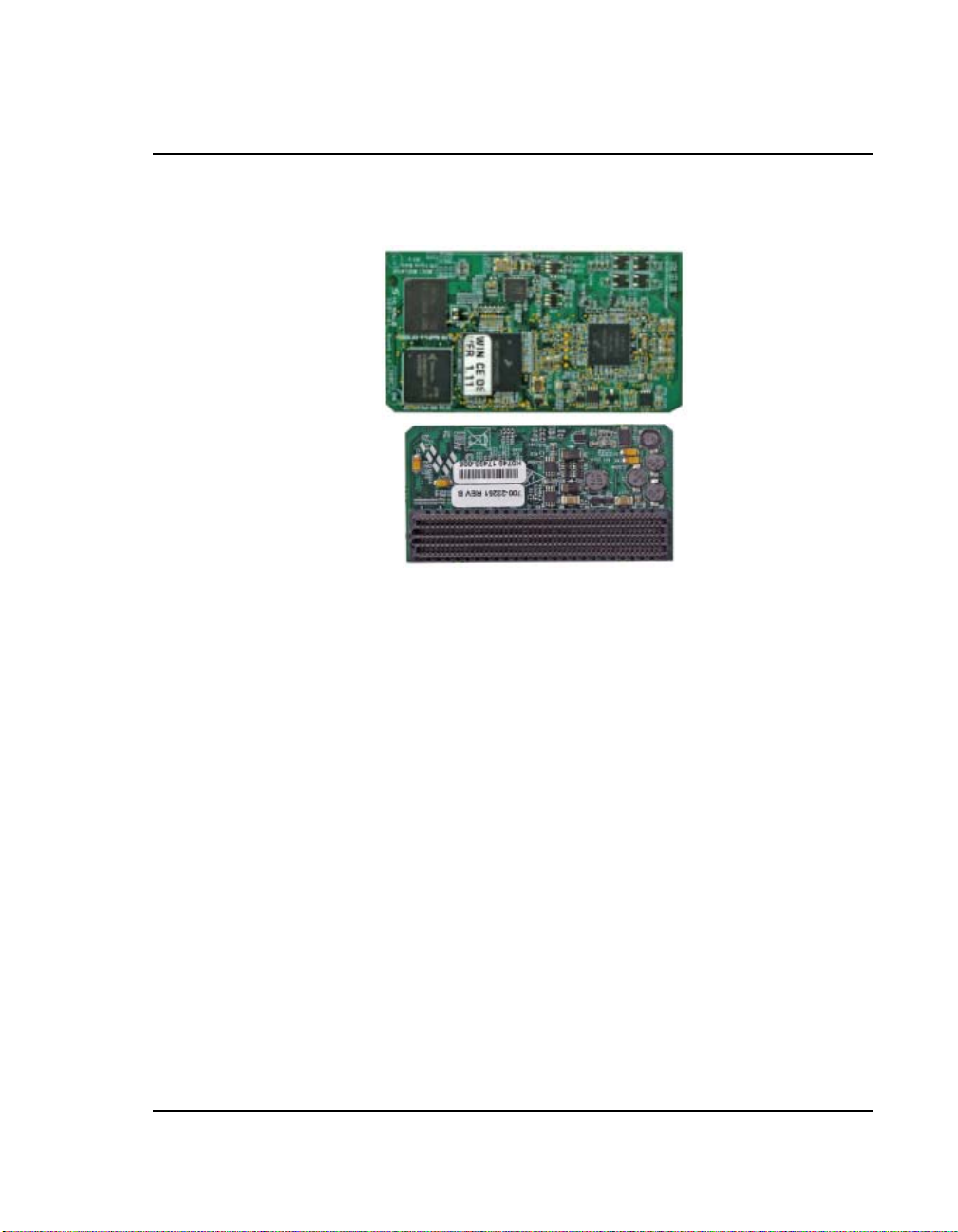
J1 Board-to-Board Connector
CPU
Board
Top
Bottom
About the Boards
CPU Board
Figure 1.1 CPU Board
You use the J 1 board-to-board connector (500 pins) to connect the CPU board to either of
the other two boards:
• Connect the CPU bo ard to a Personal ity board, for running dem os (no Debug board
is needed).
• Connect the CPU bo ard to a Debug board, (and connec t the Personality board to the
Debug board) for developing software. The Personality board plugs into the other
side of the Debug board.
i.MX31 PDK 1.4 Quick Start Guide
7
Page 10
About the Boards
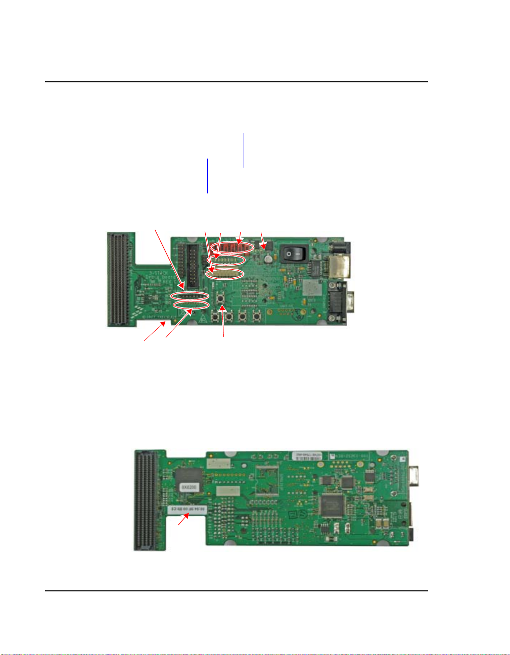
To Personality Board
Connector CN74
Current Measure J3
MX31 JTAG CN1
SW5–SW10 See Table 1.5
3.3V LED D9
Power-On S4
DC Power LED D11
DC Power J2
Ethernet J1
UART CON4
female
UART CON3
male
Device MAC
Address
Personality
CPLD JTAG
CN3
CPLD Test BT
Debug Reset S2
CPLD Test BT
Power S1
System Reset S3
CPLD LEDs D1–
SW4 See Table 1.4
Debug Board
TOP
Bottom
P1
P2
Resettable Fuse F1
To CPU Board Connector
Debug CPLD JTAG CN2
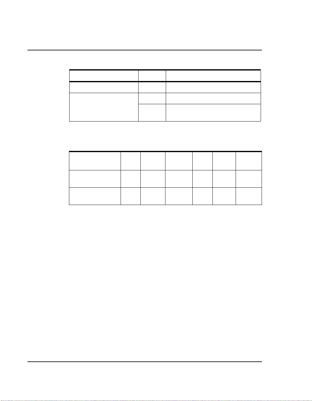
Address
MAC
Device
Debug Board
Debug Board
8
Figure 1.2 Debug Board
i.MX31 PDK 1.4 Quick Start Guide
Page 11

Table 1.2 Debug Board Physical Features
Type Physical Feature
Switches • S1: Power button
• S2: Debug board reset button
• S3: System reset switch
• S4: Power-on switch
• SW4: Enable switch
Connectors • J1:10/100 Base-T Ethernet RJ45 connector
• J2: 5.0V DC power connector
• J3: Current measure connector
• J4: 500-pin connector to CPU board
• P1: WEIM Address measure connector
• P2: WEIM Data measure connector
• CN1: i.MX31 JTAG connector
• CN2: Debug board CPLD JTAG connector
• CN3: Personality board CPLD JTAG connector (Reserved)
• CN74: 500-pin connector to Personality board
• CON4: UART (DCE) DB9 female connector
LEDs • D1–D8: LEDs for CPLD debug
• D9: LED for Debug board 3.3V power
• D11:LED for DC power supply
Buttons • BT1, BT2: Test buttons for CPLD
About the Boards
Debug Board
Fuse • F1: Resettable Fuse
i.MX31 PDK 1.4 Quick Start Guide
9
Page 12
About the Boards
Debug Board
Switch Setting Effect
SW4-1 UART Port Select ON Selects serial port UART (DCE) CON4
SW4-8 Power Enable ON Power is supplied to all three boards.
Table 1.3 Debug Board SW4 Switch
OFF Power is only supplied to the Debug
board.
Table 1.4 Boot Mode Setting (SW5–SW10)
Boot Mode
Device
UART/USB
bootloader
8-bit NAND Flash
(2KB page) Ext
SW5 Boot4
SW6
X0 0 0 0 0
X1 0 0 0 0
Boot3
SW7
SW8 SW9 SW10
10
i.MX31 PDK 1.4 Quick Start Guide
Page 13
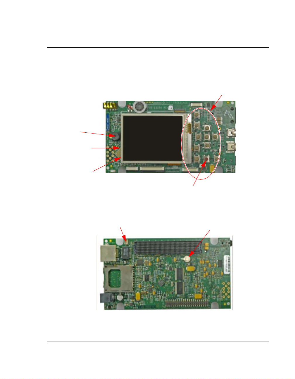
Personality Board
Bluetooth
Antenna
E2
Audio/Video
J19
USB OTG
J10
USB Host
J18
GPS CN13
GiantPlus QVGA Smart
Display J15
CMSO Sensor
CN14 (und erneath
LCD)
Debug Port fo
r
WiFi
and Bluet
o
oth CN16
ZIFF Connector
fo
r
HDD CN70
WVG
A
(n
o
t
p
o
pu
l
a
te
d
)
K
eypad Conn
ec
t
o
r
CN20
Rese
t
tab
l
e
F
us
e
F
1
TOP
On-Board
Keypad S1–S7
Fast
Ethernet
J16
SD Card
Socket
CN31
DC
Power
J12
HDD Connector CN12
Board-to-Board
Connector CN73
Coin Cell Battery
B1
Bottom
Personality
Board
WiFi Antenna
E1
Camera
R
eset
Bu
t
to
n
Epson VGA Dis play
Connector
(underneath LCD)
Battery Connector
About the Boards
Personality Board
Figure 1.3 Personality Board
i.MX31 PDK 1.4 Quick Start Guide
11
Page 14

About the Boards
Personality Board
Type Physical Feature
Connectors • CN12: 44-position dual row, 2 mm header for HDD
Battery • B1: Coin cell battery
Table 1.5 Personality Board Physical Features
• CN13: GPS module connector
• CN14: 2.0 M pixel CMOS sensor connector
• CN16: Debug port for WiFi and Bluetooth module
• CN31: SD card socket
• CN70: 40-pin ZIF connector for HDD
• CN73: 500-pin connector to CPU Engine board (in demo
configuration) or Debug board (in development configuration)
• J10: Mini-USBOTG high speed connector
• J12: 5.0 VDC power connector
• J14: Epson VGA display connector
• J15: Giantplus QVGA smart display connector
• J16: 10/100 BT Fast Ethernet Connector
• J18: Standard USB host high speed connector
• J19: Audio and video connector
12
Buttons • S7–S17: Onboard keypad
Fuse • F1: Resetable fuse
Antennas • E1: WiFi Antenna
• E2: Bluetooth antenna
i.MX31 PDK 1.4 Quick Start Guide
Page 15

Getting Started
Unpack the Kit
The 3-Stack P latform Syste m is shipped with t he items listed in Table 2.1.
Table 2.1 Contents
Type Items
Boards • CPU board
• Debug board
• Personality board
Cables • RS-232 serial cable
• Ethernet straight cable
• High-speed USB cables with mini AB
connectors for OTG
• High-speed cable with standard A to
mini B connectors
• Mini-USB adaptor
• Jack to RCA audio/video cable
Power Supply • 5.0V/2.4A universal power supply kit
2
• CD-ROMs: Content CD, Platform
Builder Trail CD, and Visual Studio
2005 Trial CD
• End-User License Agreement
• Quick Start Guide (this document)
• Warranty card
• Freescale Support card
Verify tha t all the items are contained in the packa g e. See Figure 2.1
Take out the three boards from their ant i-static bags and check the boards for any visible
damage.
i.MX31 PDK 1.4 Quick Start Guide
.
13
Page 16

Getting Started
RS-232
CD-ROM
A to Mini B
USB Cable
CPU
Board
Debug
Board
Universal
Power
Supply
Personality
Board
Ethernet
Straight Cable
Mini-AB
Jack to RCA
Audio/Video Cable
A to Mini-B
USB Cable
USB OTG
Unpack the Kit
Figure 2.1 PDK Kit Contents
14
i.MX31 PDK 1.4 Quick Start Guide
Page 17

CD-ROM Contents
Table 2.3.identifies the items on the CD-ROM set.
Table 2.2 Development PC Requirements
Type Requirement
Getting Started
CD-ROM Contents
Product
Documentation
Software
Development Tools
• i.MX31 PDK Product Brief
• Bill of Materials, Schematics, and Gerber files for
CPU Board, Personality Board, and Debug Board
• i.MX31 Demo Image Readme for Windows CE 5.0
and Windows Embedded CE 6.0
• i.MX Platform Hardware User’s Guide
• i.MX31 PDK Quick Start Guides for Windows CE
5.0/Windows Embedded CE 6.0 (this document)
• i.MX31 PDK Release Notes for Windows CE 5.0
and Windows Embedded CE 6.0
• i.MX31 PDK User’s Guides for Windows CE 5.0
and Windows Embedded CE 6.0
• i.MX31 PDK Reference Manuals for Windows CE
5.0 and Windows Embedded CE 6.0
• i.MX31 PDK Hello World Application Notes for
Windows CE 5.0 and Windows Embedded CE 6.0
• Data sheets for the i.MX31 PDK Platform’s nonFreescale components
• i.MX Platform Advanced ToolKit (ATK) User’s
Guide
• Microsoft Platform Builder, versions 5.0/6.0
• Visual Studio 2005
• Windows CE 6.0/Windows Embedded CE 6.0 SDK
installation file
• Advanced ToolKit (ATK) software
i.MX31 PDK 1.4 Quick Start Guide
15
Page 18

Getting Started
Provide a Development PC
Provide a Development PC
To develop applications usi ng the 3-Stack development kit, get a PC with the
require m ents listed in Table 2.3
Table 2.3 Development PC Requirements
Type Requirement
.
Operating System • Windows XP Professional with Service Pack 1
Network • Internet access
Software Tools • Microsoft .NET Framework, version 1.1
PC HW • 933 MHz Pentium II or later processor;
or
Windows 2000 Professional with Service Pack 4
2 GHz processor recommended
• 512 MB of RAM;
1 GB recommended
• 1 GB of available space required on system drive
• 18 GB of available hard-disk space
•DVD ROM drive
• 1024x768 or higher resolution display with 256
colors
16
i.MX31 PDK 1.4 Quick Start Guide
Page 19

Build the Platform
Development
Configuration
Personality Board
Debug Board
CPU Board
Demo
Configuration
Personality Board
CPU Board
3 Board Stack 2 Board Stack
This chapter explains how to connect the three types of 3-Stack boards (Debug,
Personality, CPU) together, to make either a development platform (Personality board +
CPU board + Debug board), or a demonstration platform (Personality board + CPU
board); and how to connect the 3-Stack platform to your PC. See Fi gure 3.1
Figure 3.1 3-Stack Platform Configurations
3
.
The three 3-Stack boards in your develo pm ent kit may already be assembl ed. If the three
boards ar e alre ady ass embled, re vi ew the pr oce dur es in t he f ollowi ng s ect ions , an d be sure
to configure the Debug board appropriately.
• To build a development platform, follow the procedures in “Build a Development
Platform: Assemble Three Boards” on page 17.
• To build a demonstration pla tform, follow the procedures in “Bui l d a D emo
Platform: Assemble Two Boards” on page 21.
Build a Development Platform: Assemble Three Boards
This section explains how to connect the Personal ity, Debug, and CPU boards.
i.MX31 PDK 1.4 Quick Start Guide
17
Page 20

Build the Platform
Personality
Board
Debug
Board
Align boards
PersonalityBoard
Debug
Board
1
2
Connect boards
Personality
Board
Debug
Board
Build a Development Platform: Assemble Three Boards
Connect Personality Board to Debug Board
The Personality board connects to the Debug board using a 500-pin connector. The
connecto r is keyed to avoid misconnection, so there is only one way t o connect these
boards. Connec t th e Person al ity boar d to the Debug boar d. The maxi mum all owa ble angl e
for mating and unma ting boar ds is 10 de gre es . See Figure 3.2
see: http:/ /samtec.com/ftppub /TESTRPT/tc076--1254rep ortrev3.pdf.
. For additional information,
18
Figure 3.2 Install Personality Board onto Debug Board
i.MX31 PDK 1.4 Quick Start Guide
Page 21

Personality Board
Debug Board
CPU
Board
Flip over Personality/
Debug assembly
1
2
Align boards
3
Connect CPU board to
underside of Debug
board
Personality Board
Debug Board
CPU Board
CPU Board
Build the Platform
Build a Development Platform: Assemble Three Boards
Connect CPU Board to Debug Board
After connect i ng the Per so nalit y bo ard to t he Deb ug bo ard, no w conn ect the CPU board t o
the unders ide of the Debug board.
Figure 3.3 Align CPU board and Debug/Personality board
i.MX31 PDK 1.4 Quick Start Guide
19
Page 22

Build the Platform
RS-232
cable
COM port
Female
1
3
4
5
6
DC
power
Regulated +5V
DC Supply
J2
S4
Configure serial
console application.
Set Bootstrap switches
(SW5–SW10) to NAND boot
2
Set SW4
Build a Development Platform: Assemble Three Boards
Connect Development Platform to PC; Run Preloaded Image
Figure 3.4 Connecting the Platform to your PC
To connect the 3-Stack platform to your host PC:
1. Connect one end of an RS-232 serial cabl e (included in the kit) to a serial port
connector (CO N4 ) on the Deb ug b oar d and co nne ct the ot her en d to a COM po rt on t he
host PC.
• Confi gure SW4-1 to ON.
• Make sure that SW4-8 is ON, to supply power to all three boards.
• Configure SW4-2 to OFF.
2. Confirm that the Bootstrap switches (SW5–SW10) are set for NAND boot. See Table
3.1.
Table 3.1 Boot Mode Setting (SW5–SW10)
20
Boot Mode
Device
UART/USB
bootloader
8-bit NAND Flash
(2KB page) Ext
SW5 SW6
(Boot4)
X0 0 0 0 0
X1 0 0 0 0
i.MX31 PDK 1.4 Quick Start Guide
SW7
(Boot3)
SW8 SW9 SW10
Page 23

Build the Platform
Build a Demo Platform: Assemble Two Boards
3. Connect the regulated 5V power supply to the appropriate power adapter. Plug the
power adapte r into an electrical outlet and the 5V li ne connector into the J2 (5V
POWER JACK) connector on the Debug board. See Figure 3-5.
4. Start a serial conso le application on your host PC with the following configuration
Table 3.2 Serial Console Configuration
Baud Rate 115200
Data Bits
Parity
Stop Bits
Flow Control
5. On the Debug board, swit ch the power switch (S4) to 1.
6. The OS image pre- loaded in the 3-Stack board will boot and the de bug messages from
the bootloader should now appear on the se rial console application on your PC.
8
None
1
None
Build a Demo Platform: Assemble Two
Boards
This section explains how to make a demonstration platform using the Personality and
CPU boards.
To make a demonstra ti on plat fo rm, the CPU bo ard is dire ctly conne ct ed to the Perso nal it y
board using the 500-pin connector; the Debug board is not used.
NOTE If your system is already configured as a development platform (using a ll three
boards), disconnect all boards from each other.
i.MX31 PDK 1.4 Quick Start Guide
21
Page 24

Build the Platform
Personality Board
CPU Board
Personality Board
CPU Board
Flip over Personality/
1
2
Align boards
Personality
Board
Personality
Board
Personality/CPU
Assembly
3
Install CPU board onto
underside of Personality
board
CPU Board
Build a Demo Platform: Assemble Two Boards
Connect CPU Board to Personality Board
Connect the CPU board to the Perso nality board. The connector is keyed to avoid
misconnec tions, so that there is only one w ay to connect the CPU board to the Personality
board.
22
Figure 3.5 Install CPU Board onto Personality Board
i.MX31 PDK 1.4 Quick Start Guide
Page 25

Build the Platform
CPU/Personality Board
DC
power
Regulated +5V
DC Supply
J12 power jack is on the underside
of the Personality board
1
2
Build a Demo Platform: Assemble Two Boards
Connect Power Supply; Run Preloaded Demo
1. Connect the regulated 5V power supply to the appropriate power adapter. Plug the 5V
2. The OS image pre-loaded in the 3-Stack sh ould boot and the Windows CE 5.0 or
Figure 3.6 Connect Personality Board to Power Supply
line into the J12 (5V POWER JACK) connector on the Personality board. See Figure
3.6. Turn the 5V power supply ON.
Windows Embedded CE 6.0 o per atin g sys tem should a ppe ar a t the Pe rso nali ty bo ard’s
LCD display.
i.MX31 PDK 1.4 Quick Start Guide
23
Page 26

Build the Platform
Build a Demo Platform: Assemble Two Boards
24
i.MX31 PDK 1.4 Quick Start Guide
Page 27

Using the Demo Image
This chapter expl ains ho w to us e th e touch pa nel and sty lus to load the mul timed ia cont ent
to the 3-Stack board, using the provided demo image.
Multimedia Codecs Content
The Windows CE 5.0 and Windows Embedded CE 6.0 Demo Images contain a set of
multimedia codecs tha t support various use cas es. These codecs are optimized to run on
the i.MX31 platform.
See the D e m o Im a g e R ea d m e do cumen t, pro vided w ith the dem o im ag e , fo r a full list of
the codecs provided.
These codec s are provided for demonstration purposes; therefore, they will only playback
the content for 30 seconds.
For more information about the multimedia codecs, or to obtain evaluation copies, please
contact a Freescale sales representative or distributor.
Touch Pad Calibration Tool
4
After you have assembled the 3-Stack board and powered it up, the Windows CE 5.0 or
Windows Embed ded CE 6.0 image that wa s loaded to the board will boot up. The first
i.MX31 PDK 1.4 Quick Start Guide
25
Page 28

Using the Demo Image
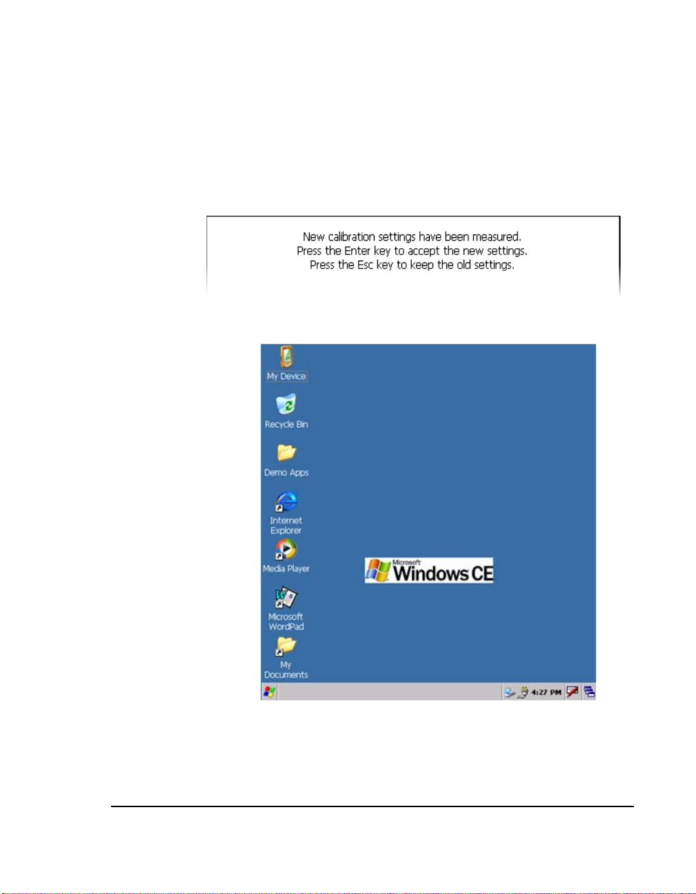
Touch Pad Calibration Tool
image you will see is the touch pa d calibration tool, which displays a cr oss in the center,
as shown in the partial screen image in Figure 4.1.
26
Figure 4.1 Touch Pad Calibration Tool
i.MX31 PDK 1.4 Quick Start Guide
Page 29
Using the Demo Image
Touch Pad Calibration Tool
To calib rate the T ou c h P an e l, fo llow the se ste ps :
1. Using the stylus pen , click on the cross.
The cross wil l m ove to the four corners of the screen. If the cali bration error is too
large, the program will reset and the process will have to be repea ted. When the touch
panel calibration is successful, the following message is displayed:
2. Tap with the stylus pen in any part of the screen.
The Windows CE desktop is displayed (see Figure 4.2.).
Figure 4.2 Windows CE Desktop
i.MX31 PDK 1.4 Quick Start Guide
27
Page 30

Using the Demo Image
Downloading Multimedia to the 3-Stack Board
Downloading Multimedia to the 3-Stack
Board
There are three ways to load multimedia content to the 3-Stack board using the Windows
CE 5.0 or Windows Embedded CE 6.0 image provided:
• Using Activ e Sync
• Using an SD Card
• Using a USB Card
Using Active Sync
Active Sync is a very useful tool to use with a Window s CE 5.0 or Windows Embedded
CE 6.0 device. To obtain the Active Sync download and instru ctions, go to:
http://www.microsoft.com/windowsmobile/activesync/activesync45.ms px/
Once Active Sync is installed, you can set up com m unication between your hos t PC and
the 3-Sta ck board.
To establish a communication between the Host PC and the 3-Stack board, follow these
steps:
1. Make sure that the 3-Stac k boa rd is ON and ru nni ng t he Wi ndows CE 5.0 or Wi ndows
Embedded CE 6.0 image.
2. Make sure that Active Sync is running on your host PC (the Active Sync icon should
appear gray o n the Windows task bar).
28
i.MX31 PDK 1.4 Quick Start Guide
Page 31
Using the Demo Image
Downloading Multimedia to the 3-Stack Board
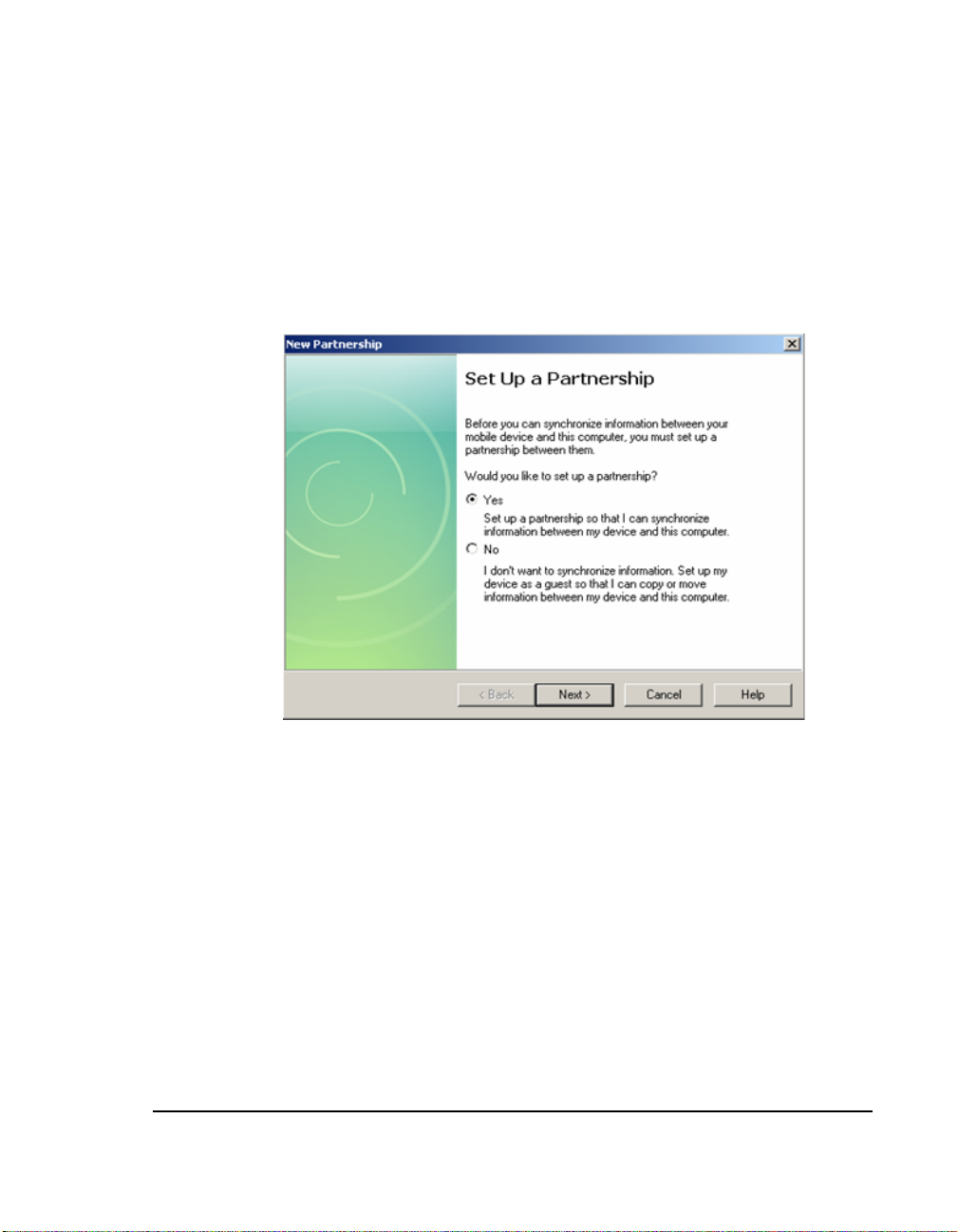
3. Use the A to mini AB USB cable provided in your i.MX 31 MAX WPDK kit and
connect the mini AB end to the J10 USB O TG connector on the Personality board,
then connec t the other end to the any available USB port on your Host PC.
Windows will r ecognize the 3-Stack boar d as a W indows CE 5.0 or Windows
Embedded CE 6.0 Devi ce and the Active Sync wizard will appear on the Host PC
(Figure 4.3).
Figure 4.3 Setting up a Partnership
i.MX31 PDK 1.4 Quick Start Guide
29
Page 32

Using the Demo Image
Downloading Multimedia to the 3-Stack Board
4. Select Yes, and then clic k Next.
The Select Synchronization Settings options are displayed (Figure 4. 4).
Figure 4.4 Selecting Synchronization Settings
30
Active Sync establishes communicati ons with the 3-St ack board, and the Active Syn c
screen displays the connection st atus (Figure 4.5).
Figure 4.5 Viewing the Connection Status
i.MX31 PDK 1.4 Quick Start Guide
Page 33

Using the Demo Image
Downloading Multimedia to the 3-Stack Board
5. To browse the Mobile De vice (3-Stack) folders, click on the Explore icon of the
Active Sync window
A new Windows Explorer window for your Mobile De vice opens on the Host PC
(Figure 4-6).
Figure 4.6 Windows Explorer for Mobile Device
6. To download a multimedia file, drag t he file to the Mobile Device wi ndow .
The Active Sync will transfer the file to the board, displa y a me ssage indicating that
the file will be converted.
7. Click OK.
8. The download begins.
NOTE For more information about the multimedia files supported by the Windows
CE 5.0 or Windows Embedded CE 6.0 image pre-loaded in the board, see the
Demo Image Readme file included in the PDK documentation.
i.MX31 PDK 1.4 Quick Start Guide
31
Page 34

Using the Demo Image
Downloading Multimedia to the 3-Stack Board
9. To access the files, double-click on the "My Device" icon in the Windows CE 5.0 or
Windows Embedded CE 6.0 desktop (on the 3-Stack board).
A Windows Explore r wi ndow wi ll ope n, disp la ying t he co ntent you do wnlo aded w ith
Active Sync (Figure 4-7).
Figure 4.7 Downloaded Content
Downloaded ContentF
10. Plug the headphones to the J19 Audio/Video jack connector in the Personality board.
11. Double-click on your multimedia file.
The Media Player opens and pla ys the file.
32
i.MX31 PDK 1.4 Quick Start Guide
Page 35

Using the Demo Image
Downloading Multimedia to the 3-Stack Board
Using an SD Card
If you have an SD Card with pic tu res or ot he r mul timedi a co ntent , y ou can use the 3-Stac k
Board to view its content.
To use access t he SD C ard, follow these steps :
1. Make sure the 3-Stack is powered and running the Windows CE 5.0 or Windows
Embedded CE 6.0 demo image.
2. Insert the SD Card in the SD Card slot, which is located in the lower part of the
personality board, just below the USB connectors.
3. Click on "My Device" i con lo cat ed in t he Wind ows CE 5.0 o r Wi ndows Embed ded CE
6.0 de sktop .
A Windows Explorer window opens, displaying the SD Memory icon (Fi gure 4-8).
Figure 4.8 Viewing the SD Memory Icon
4. To access the SD Card content, double cl ick-on the SD Memory icon.
i.MX31 PDK 1.4 Quick Start Guide
33
Page 36

Using the Demo Image
Running the Demo Applications
Using a USB Memory Stick
You must have a USB mini AB-to-A fem ale connector, for connecting the USB memory
stick to the 3-Stack board.
To use the USB memo ry stick with the 3-Stack board, follow these steps:
1. Make sure the 3-Stack is powered and running the Windows CE 5.0 or Windows
Embedded CE 6.0 demo image.
2. Connect the adapter to J18 USB Host connector on the Personality board, and connect
the USB memory stic k to th e ad a pt er.
3. Click on the "My Device" icon in the Windows CE 5.0 or Windows Em bedde d CE 6.0
desktop.
A Windows Explorer window opens, displaying the Hard Disk icon (Figure 4.9).
Figure 4.9 Viewing the Hard Disk Icon
4. Double-click the "Hard Disk" icon.
Running the Demo Applications
The Windows CE 5.0 or Wi ndow s Embedded CE 6.0 image pre-loaded in the 3-Stack
board has two applicatio ns:
• The TV-Out application all ow s you to use a TV as a display
• The Rotate application to switch the display from portrait to landscape
i.MX31 PDK 1.4 Quick Start Guide
34
Page 37

Using the Demo Image
Running the Demo Applications
Running the TV-Out Application
The TV Out appli cation has two output forma ts: PAL and NTSC. You will need a special
cable.
To use the TV-Out application, follow these steps:
1. Plug the RCA Video/Audio cable jack to the J19 Video/Audio jack on the Personality
board.
2. Connect the RCA end to the TV.
i.MX31 PDK 1.4 Quick Start Guide
35
Page 38

Using the Demo Image
Running the Demo Applications
3. Before running the appli cation, you m ust disable the power-saving features of the
Windows CE 5.0 or Windows Embedded CE 6.0 ima ge, because the TV Out signal
will be dropped if the power- saving state starts. To disable the backlight savings, tap
and hold the stylus for one or two seconds at the center of the Windows CE 5.0 or
Windows Embedded CE 6.0 desktop.
The Properties menu option is displayed ( Figure 4.10).
F
Figure 4.10 Properties Menu Option
36
i.MX31 PDK 1.4 Quick Start Guide
Page 39

Using the Demo Image
Running the Demo Applications
4. Select the Backlight tab, clear the two options on the tab, and then click OK at the top
right corner of the window (Figure 4.11).
Figure 4.11 Selecting the Background Tab
i.MX31 PDK 1.4 Quick Start Guide
37
Page 40

Using the Demo Image
Running the Demo Applications
5. The power settings on the Control Panel m ust be modified. To access the Control
Panel window, click the Windows logo at the lower left corner an d go to Settings
Control Pan el (Figure 4-12).
Figure 4.12 Selecting the Control Panel
38
i.MX31 PDK 1.4 Quick Start Guide
Page 41

6. Double-click the Pow er icon (Figure 4.13).
Figure 4.13 Selecting the Power Settings Icon
Using the Demo Image
Running the Demo Applications
i.MX31 PDK 1.4 Quick Start Guide
39
Page 42
Using the Demo Image
Running the Demo Applications
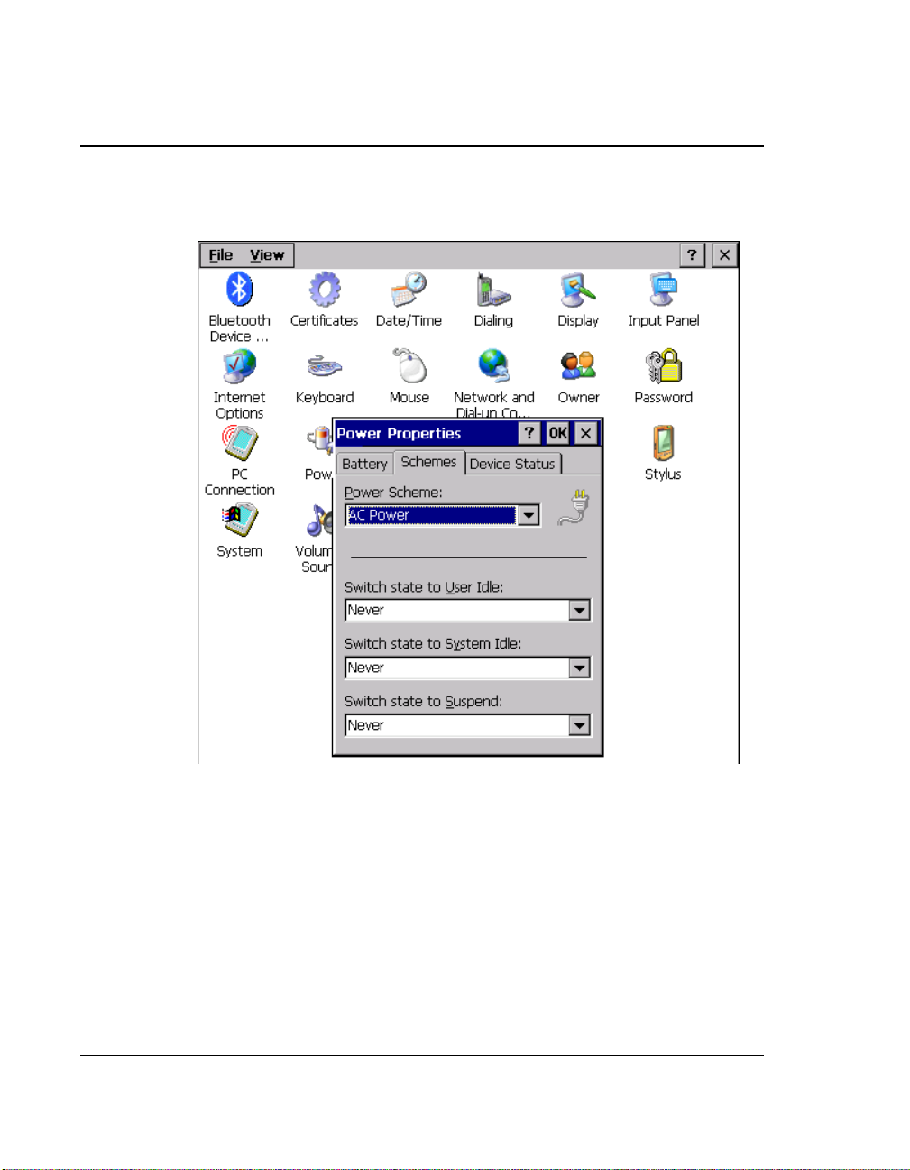
7. Select the Schemes tab (Figure 4.14).
Figure 4.14 Selecting the Schemes Tab
40
8. Change all the drop-down menu options to Never.
9. Click OK.
i.MX31 PDK 1.4 Quick Start Guide
Page 43
Using the Demo Image
Running the Demo Applications
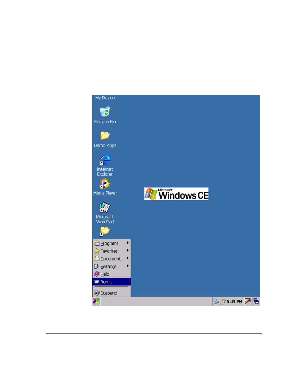
10. Now that the Pow er saving options are di sabled, you may use the TV-Out program
without a problem. To run the program, click on the Windows logo at the lower lef t
corner of the display, and then click Run (Figure 4.15).
The Ru n fi eld is dis p layed.
Figure 4.15 Selecting Run
i.MX31 PDK 1.4 Quick Start Guide
41
Page 44

Using the Demo Image
Running the Demo Applications
11. Type "tvout.exe 0" for TV s using PAL format or "tvout.exe 1" for TVs using NTSC
format, and then click OK. Figure 4.16 shows an example for a NTSC TV.
Once the program runs, the image should appear at the TV.
Figure 4.16 Example of an NTSC TV Usage
42
12. To navigate the desktop, use the keypad located below the display on the Personality
board, or you ca n conn ec t a USB mous e or keyboar d to the Pers ona lit y boa rd us ing th e
J18 USB Host conne ct or of the Per sonali t y board ( a Mini AB to A femal e ad aptor may
be require d for this option).
i.MX31 PDK 1.4 Quick Start Guide
Page 45
Using the Demo Image
Running the Demo Applications
Running the Rotate Application
The Rotate application enables you to switch the display from portrait to landscape.
To use the Rotate application, follow these st eps:
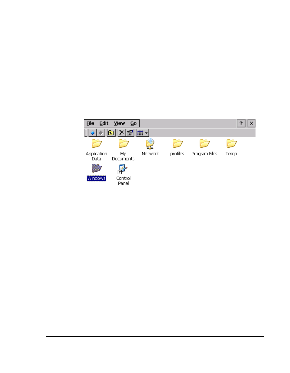
1. At the Windows CE 5.0 or Wi ndows Embedded CE 6.0 desktop, double-click on "My
Device" ic on at the top left corner.
A Windows Explorer window opens.
Figure 4.17 Opening the Windows Explorer Window
i.MX31 PDK 1.4 Quick Start Guide
43
Page 46
Using the Demo Image
Running the Demo Applications
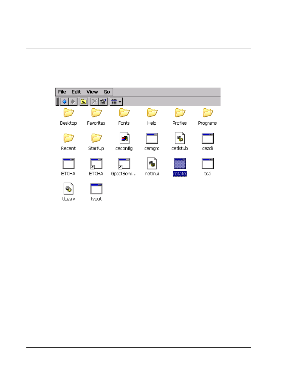
2. Locate the Rotate icon and double-click on it (Figure 4.18).
A Windows Explorer window opens.
Figure 4.18 Viewing the Icons in the Rotate Folder
44
i.MX31 PDK 1.4 Quick Start Guide
Page 47
Using the Demo Image
Running the Demo Applications
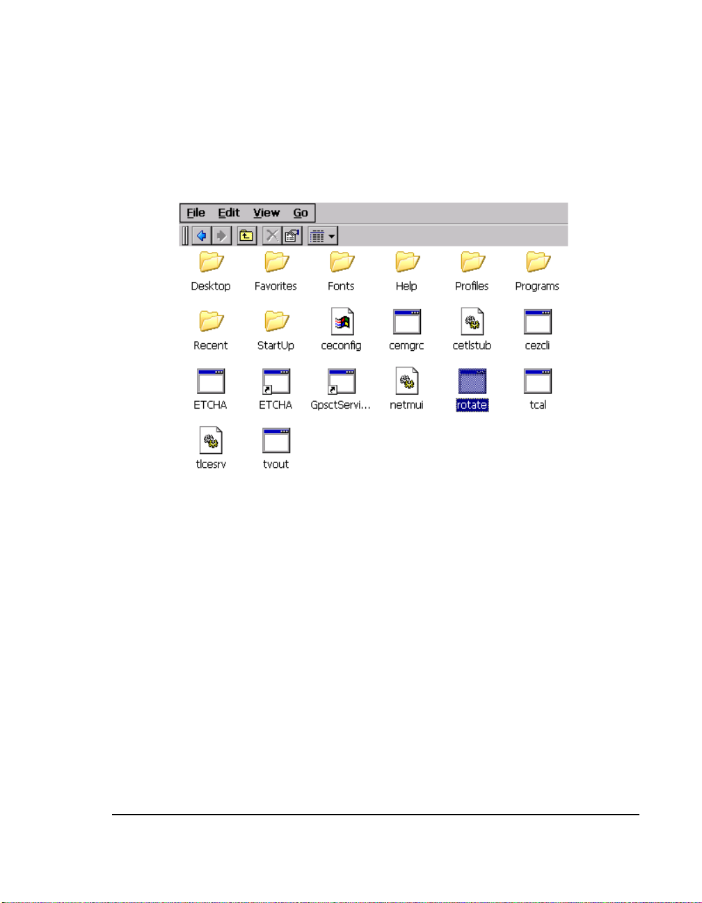
3. Clicking on the Rotate progr am toggles the display. Double-click Rotate to switch to
landscape (Figure 4.19).
Figure 4.19 Using the Rotate Application
4. To restore the port rait view, double-click the Rotate icon again.
Changing the Windows CE 5.0 or Windows Embedded CE 6.0 Demo Image Version
The PDK system provides two demo images: Windows CE 5.0 and Windows Embedded
CE 6.0.
To obtain instructions for switching images and running the selected version of the
Windows CE 5.0 or Windows Embedded CE 6.0 Demo Image on the PDK system, see
your Windows CE 5.0 or Windows Embedded CE 6.0 package, Chapter 5, Preparing for
Download and Debugging.
i.MX31 PDK 1.4 Quick Start Guide
45
Page 48

Ready to Begin Your Development?
If you are ready to develop new applications using the i.MX31 PDK, use the following
documents t o locate the information required for your developm ent:
• i.MX31 PDK 1.4 Hardware User's Guide provides all of the hardware information
for the 3-Stack board, including the connectors, switches, options, and pins.
• i.MX31 PDK 1.4 Release Notes for Windows CE 5.0 or Windows Embedded CE
6.0, provides the tools needed to use the PDK, including the driver avai lability and
known errors.
• i.MX31 PDK 1. 4 User’s Guide for Windows CE 5.0 or Windows Embedded CE 6.0
explains how to build and modify a Windows CE 5.0 or Windows Embedded CE 6.0
image and deploy the image to the 3-Stack board.
• i.MX31 PDK 1.4 Reference Manual for Windows CE 5.0 or Win dow s Embedded
CE 6.0 provides detailed information abo ut the Windows BSP drivers, including
functional informati on, dependencies, and bui lding optio ns for each driver.
• i.MX31 PDK 1.4 Hello World Application Note for Windows CE 5.0 or Windows
Embedded CE 6.0 expl ains how to crea te a sim ple Hel lo Worl d app licat i on using the
Microsoft Platform Builder 5.0/6.0.
For additional information, see the support informat ion in your i.MX31 PDK 1.4 pac kage.
i.MX31 PDK 1.4 Quick Start Guide
PN 926-23574 Rev. D
10/2008
 Loading...