

Page 1

FlexRay
Communication
freescale.com
Controllers
MFR4310RM
Rev. 2
03/2008
MFR4310
Reference Manual
Page 2

Page 3

MFR4310 Reference Manual
MFR4310RM
Rev. 2
03/2008
Page 4

To provide the most up-to-date information, the revision of our documents on the World Wide Web will
be the most current. Your printed copy may be an earlier revision. To verify that you have the latest
information available, refer to http://www.freescale.com/flexray.
The following revision history table summarizes changes made to this document.
Revision History
Date
9 May 2007 0 First public release.
20 Jun 2007 1 Added row for 1M63J maskset to Table 2-2.
21 Mar 2008 2 Revised Figure 1-1.
Revision
Level
Description
Changed Figure 4-2 read and reset values and following paragraph to reflect 1M63J maskset
as an example .
Updated Table A-1 (maximum junction temperature changed from +150C to +140C).
Updated Table A-5. Thermal Characteristics
Updated Table A-8. Supply Current Characteristics (50mA max for -40 C, 25C & 140 C).
Updated Table A-12. Oscillator Characteristics (VDCbias TYP = 2.5).
MFR4310 Reference Manual, Rev. 2
4 Freescale Semiconductor
Page 5

Introduction
Device Overview
FlexRay Module (FLEXRAYV4)
Port Integration Module (PIM)
Dual Output Voltage Regulator (VREG3V3V2)
Clocks and Reset Generator (CRG)
Oscillator (OSCV2)
Electrical Characteristics
Package Information
Printed Circuit Board Layout Recommendations
Index of Registers
MFR4310 Reference Manual, Rev. 2
Freescale Semiconductor 5
Page 6

MFR4310 Reference Manual, Rev. 2
6 Freescale Semiconductor
Page 7

Contents
Section Number Title Page
Chapter 1
Introduction
1.1 Audience . . . . . . . . . . . . . . . . . . . . . . . . . . . . . . . . . . . . . . . . . . . . . . . . . . . . . . . . . . . . . . . . . . . . . 25
1.2 Additional Reading . . . . . . . . . . . . . . . . . . . . . . . . . . . . . . . . . . . . . . . . . . . . . . . . . . . . . . . . . . . . 25
1.3 Terminology . . . . . . . . . . . . . . . . . . . . . . . . . . . . . . . . . . . . . . . . . . . . . . . . . . . . . . . . . . . . . . . . . . 26
1.4 Part Number Coding . . . . . . . . . . . . . . . . . . . . . . . . . . . . . . . . . . . . . . . . . . . . . . . . . . . . . . . . . . . . 27
Chapter 2
Device Overview
2.1 Introduction . . . . . . . . . . . . . . . . . . . . . . . . . . . . . . . . . . . . . . . . . . . . . . . . . . . . . . . . . . . . . . . . . . 29
2.2 Features . . . . . . . . . . . . . . . . . . . . . . . . . . . . . . . . . . . . . . . . . . . . . . . . . . . . . . . . . . . . . . . . . . . . . 29
2.3 Block Diagram . . . . . . . . . . . . . . . . . . . . . . . . . . . . . . . . . . . . . . . . . . . . . . . . . . . . . . . . . . . . . . . . 31
2.3.1 Memory Map . . . . . . . . . . . . . . . . . . . . . . . . . . . . . . . . . . . . . . . . . . . . . . . . . . . . . . . . . . 32
2.3.2 Part ID and Module Version Number Assignments . . . . . . . . . . . . . . . . . . . . . . . . . . . . . 33
2.4 Signal Descriptions . . . . . . . . . . . . . . . . . . . . . . . . . . . . . . . . . . . . . . . . . . . . . . . . . . . . . . . . . . . . 33
2.4.1 System Pinout . . . . . . . . . . . . . . . . . . . . . . . . . . . . . . . . . . . . . . . . . . . . . . . . . . . . . . . . . 33
2.4.2 Pin Functions and Signal Properties . . . . . . . . . . . . . . . . . . . . . . . . . . . . . . . . . . . . . . . . 35
2.4.3 Detailed Signal Descriptions . . . . . . . . . . . . . . . . . . . . . . . . . . . . . . . . . . . . . . . . . . . . . . 38
2.4.4 Power Supply Pins . . . . . . . . . . . . . . . . . . . . . . . . . . . . . . . . . . . . . . . . . . . . . . . . . . . . . . 44
2.5 Modes of Operation . . . . . . . . . . . . . . . . . . . . . . . . . . . . . . . . . . . . . . . . . . . . . . . . . . . . . . . . . . . . 45
2.6 External Clock and Host Interface Selection . . . . . . . . . . . . . . . . . . . . . . . . . . . . . . . . . . . . . . . . . 45
2.6.1 External 4/10/40 MHz Output Clock . . . . . . . . . . . . . . . . . . . . . . . . . . . . . . . . . . . . . . . . 45
2.6.2 External Host Interface Selection . . . . . . . . . . . . . . . . . . . . . . . . . . . . . . . . . . . . . . . . . . 46
2.6.3 Recommended Pullup/pulldown Resistor Values . . . . . . . . . . . . . . . . . . . . . . . . . . . . . . 47
2.7 External Host Interface . . . . . . . . . . . . . . . . . . . . . . . . . . . . . . . . . . . . . . . . . . . . . . . . . . . . . . . . . . 47
2.7.1 Asynchronous Memory Interface . . . . . . . . . . . . . . . . . . . . . . . . . . . . . . . . . . . . . . . . . . 47
2.7.2 MPC Interface . . . . . . . . . . . . . . . . . . . . . . . . . . . . . . . . . . . . . . . . . . . . . . . . . . . . . . . . . 50
2.7.3 HCS12 Interface . . . . . . . . . . . . . . . . . . . . . . . . . . . . . . . . . . . . . . . . . . . . . . . . . . . . . . . 52
2.8 Resets and Interrupts . . . . . . . . . . . . . . . . . . . . . . . . . . . . . . . . . . . . . . . . . . . . . . . . . . . . . . . . . . . 56
2.8.1 Resets . . . . . . . . . . . . . . . . . . . . . . . . . . . . . . . . . . . . . . . . . . . . . . . . . . . . . . . . . . . . . . . . 56
2.8.2 Interrupt Sources . . . . . . . . . . . . . . . . . . . . . . . . . . . . . . . . . . . . . . . . . . . . . . . . . . . . . . . 57
Chapter 3
FlexRay Module (FLEXRAYV4)
3.1 Introduction . . . . . . . . . . . . . . . . . . . . . . . . . . . . . . . . . . . . . . . . . . . . . . . . . . . . . . . . . . . . . . . . . . 59
3.1.1 Reference . . . . . . . . . . . . . . . . . . . . . . . . . . . . . . . . . . . . . . . . . . . . . . . . . . . . . . . . . . . . . 59
3.1.2 Glossary . . . . . . . . . . . . . . . . . . . . . . . . . . . . . . . . . . . . . . . . . . . . . . . . . . . . . . . . . . . . . . 59
3.1.3 Color Coding . . . . . . . . . . . . . . . . . . . . . . . . . . . . . . . . . . . . . . . . . . . . . . . . . . . . . . . . . . 60
MFR4310 Reference Manual, Rev. 2
Freescale Semiconductor 7
Page 8

Section Number Title Page
3.1.4 Overview . . . . . . . . . . . . . . . . . . . . . . . . . . . . . . . . . . . . . . . . . . . . . . . . . . . . . . . . . . . . . 60
3.1.5 Features . . . . . . . . . . . . . . . . . . . . . . . . . . . . . . . . . . . . . . . . . . . . . . . . . . . . . . . . . . . . . . 61
3.1.6 Modes of Operation . . . . . . . . . . . . . . . . . . . . . . . . . . . . . . . . . . . . . . . . . . . . . . . . . . . . . 63
3.2 External Signal Description . . . . . . . . . . . . . . . . . . . . . . . . . . . . . . . . . . . . . . . . . . . . . . . . . . . . . . 64
3.2.1 Detailed Signal Descriptions . . . . . . . . . . . . . . . . . . . . . . . . . . . . . . . . . . . . . . . . . . . . . . 64
3.3 Memory Map and Register Description . . . . . . . . . . . . . . . . . . . . . . . . . . . . . . . . . . . . . . . . . . . . . 65
3.3.1 Memory Map . . . . . . . . . . . . . . . . . . . . . . . . . . . . . . . . . . . . . . . . . . . . . . . . . . . . . . . . . . 65
3.3.2 Register Descriptions . . . . . . . . . . . . . . . . . . . . . . . . . . . . . . . . . . . . . . . . . . . . . . . . . . . . 68
3.4 Functional Description . . . . . . . . . . . . . . . . . . . . . . . . . . . . . . . . . . . . . . . . . . . . . . . . . . . . . . . . . 134
3.4.1 Message Buffer Concept . . . . . . . . . . . . . . . . . . . . . . . . . . . . . . . . . . . . . . . . . . . . . . . . 134
3.4.2 Physical Message Buffer . . . . . . . . . . . . . . . . . . . . . . . . . . . . . . . . . . . . . . . . . . . . . . . . 134
3.4.3 Message Buffer Types . . . . . . . . . . . . . . . . . . . . . . . . . . . . . . . . . . . . . . . . . . . . . . . . . . 135
3.4.4 FlexRay Memory Layout . . . . . . . . . . . . . . . . . . . . . . . . . . . . . . . . . . . . . . . . . . . . . . . . 140
3.4.5 Physical Message Buffer Description . . . . . . . . . . . . . . . . . . . . . . . . . . . . . . . . . . . . . . 142
3.4.6 Individual Message Buffer Functional Description . . . . . . . . . . . . . . . . . . . . . . . . . . . . 151
3.4.7 Individual Message Buffer Search . . . . . . . . . . . . . . . . . . . . . . . . . . . . . . . . . . . . . . . . . 176
3.4.8 Individual Message Buffer Reconfiguration . . . . . . . . . . . . . . . . . . . . . . . . . . . . . . . . . 178
3.4.9 Receive FIFO . . . . . . . . . . . . . . . . . . . . . . . . . . . . . . . . . . . . . . . . . . . . . . . . . . . . . . . . . 179
3.4.10 Channel Device Modes . . . . . . . . . . . . . . . . . . . . . . . . . . . . . . . . . . . . . . . . . . . . . . . . . 184
3.4.11 External Clock Synchronization . . . . . . . . . . . . . . . . . . . . . . . . . . . . . . . . . . . . . . . . . . 186
3.4.12 Sync Frame ID and Sync Frame Deviation Tables . . . . . . . . . . . . . . . . . . . . . . . . . . . . 186
3.4.13 MTS Generation . . . . . . . . . . . . . . . . . . . . . . . . . . . . . . . . . . . . . . . . . . . . . . . . . . . . . . 189
3.4.14 Sync Frame and Startup Frame Transmission . . . . . . . . . . . . . . . . . . . . . . . . . . . . . . . . 190
3.4.15 Sync Frame Filtering . . . . . . . . . . . . . . . . . . . . . . . . . . . . . . . . . . . . . . . . . . . . . . . . . . . 191
3.4.16 Strobe Signal Support . . . . . . . . . . . . . . . . . . . . . . . . . . . . . . . . . . . . . . . . . . . . . . . . . . 192
3.4.17 Timer Support . . . . . . . . . . . . . . . . . . . . . . . . . . . . . . . . . . . . . . . . . . . . . . . . . . . . . . . . 193
3.4.18 Slot Status Monitoring . . . . . . . . . . . . . . . . . . . . . . . . . . . . . . . . . . . . . . . . . . . . . . . . . . 194
3.4.19 Interrupt Support . . . . . . . . . . . . . . . . . . . . . . . . . . . . . . . . . . . . . . . . . . . . . . . . . . . . . . 197
3.4.20 Clock Domain Crossing . . . . . . . . . . . . . . . . . . . . . . . . . . . . . . . . . . . . . . . . . . . . . . . . . 202
3.5 Lower FlexRay Bit Rate Support . . . . . . . . . . . . . . . . . . . . . . . . . . . . . . . . . . . . . . . . . . . . . . . . . 202
3.6 Initialization Information . . . . . . . . . . . . . . . . . . . . . . . . . . . . . . . . . . . . . . . . . . . . . . . . . . . . . . . 202
3.6.1 FlexRay Initialization Sequence . . . . . . . . . . . . . . . . . . . . . . . . . . . . . . . . . . . . . . . . . . 203
3.6.2 Number of Usable Message Buffers . . . . . . . . . . . . . . . . . . . . . . . . . . . . . . . . . . . . . . . 203
3.7 Application Information . . . . . . . . . . . . . . . . . . . . . . . . . . . . . . . . . . . . . . . . . . . . . . . . . . . . . . . . 204
3.7.1 Shut Down Sequence . . . . . . . . . . . . . . . . . . . . . . . . . . . . . . . . . . . . . . . . . . . . . . . . . . . 204
3.7.2 Protocol Control Command Execution . . . . . . . . . . . . . . . . . . . . . . . . . . . . . . . . . . . . . 205
3.7.3 Protocol Reset Command . . . . . . . . . . . . . . . . . . . . . . . . . . . . . . . . . . . . . . . . . . . . . . . 206
Chapter 4
Port Integration Module (PIM)
4.1 Introduction . . . . . . . . . . . . . . . . . . . . . . . . . . . . . . . . . . . . . . . . . . . . . . . . . . . . . . . . . . . . . . . . . 207
4.1.1 Overview . . . . . . . . . . . . . . . . . . . . . . . . . . . . . . . . . . . . . . . . . . . . . . . . . . . . . . . . . . . . 207
MFR4310 Reference Manual, Rev. 2
8 Freescale Semiconductor
Page 9

Section Number Title Page
4.1.2 Features . . . . . . . . . . . . . . . . . . . . . . . . . . . . . . . . . . . . . . . . . . . . . . . . . . . . . . . . . . . . . 207
4.1.3 Modes of Operation . . . . . . . . . . . . . . . . . . . . . . . . . . . . . . . . . . . . . . . . . . . . . . . . . . . . 207
4.2 External Signal Description . . . . . . . . . . . . . . . . . . . . . . . . . . . . . . . . . . . . . . . . . . . . . . . . . . . . . 207
4.2.1 Functional Mode . . . . . . . . . . . . . . . . . . . . . . . . . . . . . . . . . . . . . . . . . . . . . . . . . . . . . . 208
4.2.2 Reset Mode . . . . . . . . . . . . . . . . . . . . . . . . . . . . . . . . . . . . . . . . . . . . . . . . . . . . . . . . . . 209
4.3 PIM Memory Map and Registers . . . . . . . . . . . . . . . . . . . . . . . . . . . . . . . . . . . . . . . . . . . . . . . . . 209
4.3.1 Port Integration Module Registers . . . . . . . . . . . . . . . . . . . . . . . . . . . . . . . . . . . . . . . . . 210
4.4 Functional Description . . . . . . . . . . . . . . . . . . . . . . . . . . . . . . . . . . . . . . . . . . . . . . . . . . . . . . . . . 215
4.4.1 Functional Mode . . . . . . . . . . . . . . . . . . . . . . . . . . . . . . . . . . . . . . . . . . . . . . . . . . . . . . 215
4.4.2 Reset Mode . . . . . . . . . . . . . . . . . . . . . . . . . . . . . . . . . . . . . . . . . . . . . . . . . . . . . . . . . . 216
Chapter 5
Dual Output Voltage Regulator (VREG3V3V2)
5.1 Introduction . . . . . . . . . . . . . . . . . . . . . . . . . . . . . . . . . . . . . . . . . . . . . . . . . . . . . . . . . . . . . . . . . 217
5.1.1 Features . . . . . . . . . . . . . . . . . . . . . . . . . . . . . . . . . . . . . . . . . . . . . . . . . . . . . . . . . . . . . 217
5.1.2 Modes of Operation . . . . . . . . . . . . . . . . . . . . . . . . . . . . . . . . . . . . . . . . . . . . . . . . . . . . 217
5.1.3 Block Diagram . . . . . . . . . . . . . . . . . . . . . . . . . . . . . . . . . . . . . . . . . . . . . . . . . . . . . . . . 217
5.2 External Signal Description . . . . . . . . . . . . . . . . . . . . . . . . . . . . . . . . . . . . . . . . . . . . . . . . . . . . . 219
5.2.1 V
5.2.2 V
5.2.3 V
5.2.4 V
5.3 Functional Description . . . . . . . . . . . . . . . . . . . . . . . . . . . . . . . . . . . . . . . . . . . . . . . . . . . . . . . . . 220
5.3.1 REG — Regulator Core . . . . . . . . . . . . . . . . . . . . . . . . . . . . . . . . . . . . . . . . . . . . . . . . . 220
5.3.2 Full-performance Mode . . . . . . . . . . . . . . . . . . . . . . . . . . . . . . . . . . . . . . . . . . . . . . . . . 220
5.3.3 POR — Power On Reset . . . . . . . . . . . . . . . . . . . . . . . . . . . . . . . . . . . . . . . . . . . . . . . . 220
5.3.4 LVR — Low Voltage Reset . . . . . . . . . . . . . . . . . . . . . . . . . . . . . . . . . . . . . . . . . . . . . . 221
5.3.5 CTRL — Regulator Control . . . . . . . . . . . . . . . . . . . . . . . . . . . . . . . . . . . . . . . . . . . . . 221
5.4 Resets . . . . . . . . . . . . . . . . . . . . . . . . . . . . . . . . . . . . . . . . . . . . . . . . . . . . . . . . . . . . . . . . . . . . . . 221
5.4.1 Power On Reset . . . . . . . . . . . . . . . . . . . . . . . . . . . . . . . . . . . . . . . . . . . . . . . . . . . . . . . 221
5.4.2 Low Voltage Reset . . . . . . . . . . . . . . . . . . . . . . . . . . . . . . . . . . . . . . . . . . . . . . . . . . . . . 221
, V
DDR
, V
DDA
DD2_5
DDOSC
— Regulator Power Input . . . . . . . . . . . . . . . . . . . . . . . . . . . . . . . . . . . . . 219
SSR
— Regulator Reference Supply . . . . . . . . . . . . . . . . . . . . . . . . . . . . . . . . 219
SSA
, V
, V
— Regulator Output1 (Core Logic) . . . . . . . . . . . . . . . . . . . . . . . . . . 220
SS2_5
— Regulator Output2 (OSC) . . . . . . . . . . . . . . . . . . . . . . . . . . . . . . 220
SSOSC
Chapter 6
Clocks and Reset Generator (CRG)
6.1 Introduction . . . . . . . . . . . . . . . . . . . . . . . . . . . . . . . . . . . . . . . . . . . . . . . . . . . . . . . . . . . . . . . . . 223
6.1.1 Overview . . . . . . . . . . . . . . . . . . . . . . . . . . . . . . . . . . . . . . . . . . . . . . . . . . . . . . . . . . . . 223
6.1.2 Features . . . . . . . . . . . . . . . . . . . . . . . . . . . . . . . . . . . . . . . . . . . . . . . . . . . . . . . . . . . . . 223
6.2 MFR4310 Relevant Pins for the CRG . . . . . . . . . . . . . . . . . . . . . . . . . . . . . . . . . . . . . . . . . . . . . 224
6.3 CRG Registers . . . . . . . . . . . . . . . . . . . . . . . . . . . . . . . . . . . . . . . . . . . . . . . . . . . . . . . . . . . . . . . 224
6.3.1 Detection Enable Register (DER) . . . . . . . . . . . . . . . . . . . . . . . . . . . . . . . . . . . . . . . . . 224
6.3.2 Clock and Reset Status Register (CRSR) . . . . . . . . . . . . . . . . . . . . . . . . . . . . . . . . . . . 225
6.4 Functional Description . . . . . . . . . . . . . . . . . . . . . . . . . . . . . . . . . . . . . . . . . . . . . . . . . . . . . . . . . 226
MFR4310 Reference Manual, Rev. 2
Freescale Semiconductor 9
Page 10

Section Number Title Page
6.4.1 Reset Generation . . . . . . . . . . . . . . . . . . . . . . . . . . . . . . . . . . . . . . . . . . . . . . . . . . . . . . 226
6.4.2 Interface Selection . . . . . . . . . . . . . . . . . . . . . . . . . . . . . . . . . . . . . . . . . . . . . . . . . . . . . 229
6.4.3 CLKOUT Mode Selection and Control . . . . . . . . . . . . . . . . . . . . . . . . . . . . . . . . . . . . . 230
Chapter 7
Oscillator (OSCV2)
7.1 Introduction . . . . . . . . . . . . . . . . . . . . . . . . . . . . . . . . . . . . . . . . . . . . . . . . . . . . . . . . . . . . . . . . . 235
7.1.1 Features . . . . . . . . . . . . . . . . . . . . . . . . . . . . . . . . . . . . . . . . . . . . . . . . . . . . . . . . . . . . . 235
7.1.2 Modes of Operation . . . . . . . . . . . . . . . . . . . . . . . . . . . . . . . . . . . . . . . . . . . . . . . . . . . . 235
7.2 External Signal Description . . . . . . . . . . . . . . . . . . . . . . . . . . . . . . . . . . . . . . . . . . . . . . . . . . . . . 235
7.2.1 V
DDOSC
and V
SSOSC
— OSC Operating Voltage, OSC Ground . . . . . . . . . . . . . . . . . . 235
7.2.2 EXTAL and XTAL — Clock/Crystal Source Pins . . . . . . . . . . . . . . . . . . . . . . . . . . . . 235
7.3 Memory Map and Register Definition . . . . . . . . . . . . . . . . . . . . . . . . . . . . . . . . . . . . . . . . . . . . . 236
7.4 Functional Description . . . . . . . . . . . . . . . . . . . . . . . . . . . . . . . . . . . . . . . . . . . . . . . . . . . . . . . . . 236
7.4.1 Clock Monitor (CM) . . . . . . . . . . . . . . . . . . . . . . . . . . . . . . . . . . . . . . . . . . . . . . . . . . . 236
7.5 Resets . . . . . . . . . . . . . . . . . . . . . . . . . . . . . . . . . . . . . . . . . . . . . . . . . . . . . . . . . . . . . . . . . . . . . . 236
Appendix A
Electrical Characteristics
A.1 General . . . . . . . . . . . . . . . . . . . . . . . . . . . . . . . . . . . . . . . . . . . . . . . . . . . . . . . . . . . . . . . . . . . . . 237
A.1.1 Parameter Classification . . . . . . . . . . . . . . . . . . . . . . . . . . . . . . . . . . . . . . . . . . . . . . . . . 237
A.1.2 Power Supply . . . . . . . . . . . . . . . . . . . . . . . . . . . . . . . . . . . . . . . . . . . . . . . . . . . . . . . . . 238
A.1.3 Pins . . . . . . . . . . . . . . . . . . . . . . . . . . . . . . . . . . . . . . . . . . . . . . . . . . . . . . . . . . . . . . . . . 238
A.1.4 Current Injection. . . . . . . . . . . . . . . . . . . . . . . . . . . . . . . . . . . . . . . . . . . . . . . . . . . . . . . 238
A.1.5 Absolute Maximum Ratings. . . . . . . . . . . . . . . . . . . . . . . . . . . . . . . . . . . . . . . . . . . . . . 239
A.1.6 ESD Protection and Latch-up Immunity . . . . . . . . . . . . . . . . . . . . . . . . . . . . . . . . . . . . 240
A.1.7 Operating Conditions . . . . . . . . . . . . . . . . . . . . . . . . . . . . . . . . . . . . . . . . . . . . . . . . . . . 241
A.1.8 Power Dissipation and Thermal Characteristics. . . . . . . . . . . . . . . . . . . . . . . . . . . . . . . 241
A.1.9 I/O Characteristics . . . . . . . . . . . . . . . . . . . . . . . . . . . . . . . . . . . . . . . . . . . . . . . . . . . . . 244
A.1.10 Supply Currents . . . . . . . . . . . . . . . . . . . . . . . . . . . . . . . . . . . . . . . . . . . . . . . . . . . . . . . 246
A.2 Voltage Regulator (VREG). . . . . . . . . . . . . . . . . . . . . . . . . . . . . . . . . . . . . . . . . . . . . . . . . . . . . . 247
A.2.1 Operating Conditions . . . . . . . . . . . . . . . . . . . . . . . . . . . . . . . . . . . . . . . . . . . . . . . . . . . 247
A.2.2 Chip Power-up and Voltage Drops. . . . . . . . . . . . . . . . . . . . . . . . . . . . . . . . . . . . . . . . . 248
A.2.3 Output Loads. . . . . . . . . . . . . . . . . . . . . . . . . . . . . . . . . . . . . . . . . . . . . . . . . . . . . . . . . . 248
A.3 Reset and Oscillator . . . . . . . . . . . . . . . . . . . . . . . . . . . . . . . . . . . . . . . . . . . . . . . . . . . . . . . . . . . 249
A.3.1 Startup. . . . . . . . . . . . . . . . . . . . . . . . . . . . . . . . . . . . . . . . . . . . . . . . . . . . . . . . . . . . . . . 249
A.3.2 Oscillator. . . . . . . . . . . . . . . . . . . . . . . . . . . . . . . . . . . . . . . . . . . . . . . . . . . . . . . . . . . . . 250
A.4 Asynchronous Memory Interface Timing. . . . . . . . . . . . . . . . . . . . . . . . . . . . . . . . . . . . . . . . . . . 250
A.5 MPC Interface Timing . . . . . . . . . . . . . . . . . . . . . . . . . . . . . . . . . . . . . . . . . . . . . . . . . . . . . . . . . 252
A.6 HCS12 Interface Timing. . . . . . . . . . . . . . . . . . . . . . . . . . . . . . . . . . . . . . . . . . . . . . . . . . . . . . . . 255
MFR4310 Reference Manual, Rev. 2
10 Freescale Semiconductor
Page 11

Section Number Title Page
Appendix B
Package Information
B.1 64-pin LQFP package . . . . . . . . . . . . . . . . . . . . . . . . . . . . . . . . . . . . . . . . . . . . . . . . . . . . . . . . . . 257
Appendix C
Printed Circuit Board Layout Recommendations
Appendix D
Index of Registers
MFR4310 Reference Manual, Rev. 2
Freescale Semiconductor 11
Page 12

Section Number Title Page
MFR4310 Reference Manual, Rev. 2
12 Freescale Semiconductor
Page 13

List of Figures
Figure Number Title Page
Figure 1-1. Order Part Number Coding. . . . . . . . . . . . . . . . . . . . . . . . . . . . . . . . . . . . . . . . . . . . . . . . 27
Figure 2-1. MFR4310 Functional Block Diagram . . . . . . . . . . . . . . . . . . . . . . . . . . . . . . . . . . . . . . . 31
Figure 2-2. MFR4310 Pin Assignment . . . . . . . . . . . . . . . . . . . . . . . . . . . . . . . . . . . . . . . . . . . . . . . . 34
Figure 2-3. Oscillator Connections . . . . . . . . . . . . . . . . . . . . . . . . . . . . . . . . . . . . . . . . . . . . . . . . . . . 43
Figure 2-4. External Square Wave Clock Generator Connection . . . . . . . . . . . . . . . . . . . . . . . . . . . . 43
Figure 2-5. AMI Interface with S12X Family. . . . . . . . . . . . . . . . . . . . . . . . . . . . . . . . . . . . . . . . . . . 49
Figure 2-6. AMI Interface with DSP 56F83 (Hawk) Family . . . . . . . . . . . . . . . . . . . . . . . . . . . . . . . 50
Figure 2-7. MPC EBI Interface with MPC5xx and MPC55xx Families. . . . . . . . . . . . . . . . . . . . . . . 52
Figure 2-8. HCS12 Interface Address Decoding and Internal Chip Select Generation . . . . . . . . . . . 54
Figure 2-9. HCS12 interface with HCS12 Page Mode Support . . . . . . . . . . . . . . . . . . . . . . . . . . . . . 55
Figure 2-10. HCS12 interface with HCS12 Unpaged Mode Support. . . . . . . . . . . . . . . . . . . . . . . . . . 56
Figure 3-1. FlexRay Module Block Diagram . . . . . . . . . . . . . . . . . . . . . . . . . . . . . . . . . . . . . . . . . . . 61
Figure 3-2. Module Version Register (MVR) . . . . . . . . . . . . . . . . . . . . . . . . . . . . . . . . . . . . . . . . . . . 70
Figure 3-3. Module Configuration Register (MCR) . . . . . . . . . . . . . . . . . . . . . . . . . . . . . . . . . . . . . . 70
Figure 3-4. Strobe Signal Control Register (STBSCR). . . . . . . . . . . . . . . . . . . . . . . . . . . . . . . . . . . . 72
Figure 3-5. Message Buffer Data Size Register (MBDSR). . . . . . . . . . . . . . . . . . . . . . . . . . . . . . . . . 75
Figure 3-6. Message Buffer Segment Size and Utilization Register (MBSSUTR). . . . . . . . . . . . . . . 76
Figure 3-7. Protocol Operation Control Register (POCR) . . . . . . . . . . . . . . . . . . . . . . . . . . . . . . . . . 77
Figure 3-8. Global Interrupt Flag and Enable Register (GIFER) . . . . . . . . . . . . . . . . . . . . . . . . . . . . 78
Figure 3-9. Protocol Interrupt Flag Register 0 (PIFR0) . . . . . . . . . . . . . . . . . . . . . . . . . . . . . . . . . . . 81
Figure 3-10. Protocol Interrupt Flag Register 1 (PIFR1) . . . . . . . . . . . . . . . . . . . . . . . . . . . . . . . . . . . 83
Figure 3-11. Protocol Interrupt Enable Register 0 (PIER0) . . . . . . . . . . . . . . . . . . . . . . . . . . . . . . . . . 84
Figure 3-12. Protocol Interrupt Enable Register 1 (PIER1) . . . . . . . . . . . . . . . . . . . . . . . . . . . . . . . . . 85
Figure 3-13. CHI Error Flag Register (CHIERFR). . . . . . . . . . . . . . . . . . . . . . . . . . . . . . . . . . . . . . . . 86
Figure 3-14. Message Buffer Interrupt Vector Register (MBIVEC). . . . . . . . . . . . . . . . . . . . . . . . . . . 88
Figure 3-15. Channel A Status Error Counter Register (CASERCR). . . . . . . . . . . . . . . . . . . . . . . . . . 89
Figure 3-16. Channel B Status Error Counter Register (CBSERCR). . . . . . . . . . . . . . . . . . . . . . . . . . 89
Figure 3-17. Protocol Status Register 0 (PSR0) . . . . . . . . . . . . . . . . . . . . . . . . . . . . . . . . . . . . . . . . . . 90
Figure 3-18. Protocol Status Register 1 (PSR1) . . . . . . . . . . . . . . . . . . . . . . . . . . . . . . . . . . . . . . . . . . 91
Figure 3-19. Protocol Status Register 2 (PSR2) . . . . . . . . . . . . . . . . . . . . . . . . . . . . . . . . . . . . . . . . . . 92
Figure 3-20. Protocol Status Register 3 (PSR3) . . . . . . . . . . . . . . . . . . . . . . . . . . . . . . . . . . . . . . . . . . 94
Figure 3-21. Macrotick Counter Register (MTCTR) . . . . . . . . . . . . . . . . . . . . . . . . . . . . . . . . . . . . . . 96
MFR4310 Reference Manual, Rev. 2
Freescale Semiconductor 13
Page 14

Figure Number Title Page
Figure 3-22. Cycle Counter Register (CYCTR) . . . . . . . . . . . . . . . . . . . . . . . . . . . . . . . . . . . . . . . . . . 96
Figure 3-23. Slot Counter Channel A Register (SLTCTAR) . . . . . . . . . . . . . . . . . . . . . . . . . . . . . . . . 97
Figure 3-24. Slot Counter Channel B Register (SLTCTBR). . . . . . . . . . . . . . . . . . . . . . . . . . . . . . . . . 97
Figure 3-25. Rate Correction Value Register (RTCORVR) . . . . . . . . . . . . . . . . . . . . . . . . . . . . . . . . . 97
Figure 3-26. Offset Correction Value Register (OFCORVR). . . . . . . . . . . . . . . . . . . . . . . . . . . . . . . . 98
Figure 3-27. Combined Interrupt Flag Register (CIFRR). . . . . . . . . . . . . . . . . . . . . . . . . . . . . . . . . . . 98
Figure 3-28. Sync Frame Counter Register (SFCNTR) . . . . . . . . . . . . . . . . . . . . . . . . . . . . . . . . . . . 100
Figure 3-29. Sync Frame Table Offset Register (SFTOR) . . . . . . . . . . . . . . . . . . . . . . . . . . . . . . . . . 100
Figure 3-30. Sync Frame Table Configuration, Control, Status Register (SFTCCSR). . . . . . . . . . . . 101
Figure 3-31. Sync Frame ID Rejection Filter Register (SFIDRFR) . . . . . . . . . . . . . . . . . . . . . . . . . . 102
Figure 3-32. Sync Frame ID Acceptance Filter Value Register (SFIDAFVR). . . . . . . . . . . . . . . . . . 103
Figure 3-33. Sync Frame ID Acceptance Filter Mask Register (SFIDAFMR). . . . . . . . . . . . . . . . . . 103
Figure 3-34. Network Management Vector Registers (NMVR0–NMVR5). . . . . . . . . . . . . . . . . . . . 103
Figure 3-35. Network Management Vector Length Register (NMVLR) . . . . . . . . . . . . . . . . . . . . . . 104
Figure 3-36. Timer Configuration and Control Register (TICCR) . . . . . . . . . . . . . . . . . . . . . . . . . . . 105
Figure 3-37. Timer 1 Cycle Set Register (TI1CYSR). . . . . . . . . . . . . . . . . . . . . . . . . . . . . . . . . . . . . 106
Figure 3-38. Timer 1 Macrotick Offset Register (TI1MTOR) . . . . . . . . . . . . . . . . . . . . . . . . . . . . . . 106
Figure 3-39. Timer 2 Configuration Register 0 (TI2CR0) . . . . . . . . . . . . . . . . . . . . . . . . . . . . . . . . . 107
Figure 3-40. Timer 2 Configuration Register 1 (TI2CR1) . . . . . . . . . . . . . . . . . . . . . . . . . . . . . . . . . 107
Figure 3-41. Slot Status Selection Register (SSSR) . . . . . . . . . . . . . . . . . . . . . . . . . . . . . . . . . . . . . . 108
Figure 3-42. Slot Status Counter Condition Register (SSCCR) . . . . . . . . . . . . . . . . . . . . . . . . . . . . . 109
Figure 3-43. Slot Status Registers (SSR0–SSR7) . . . . . . . . . . . . . . . . . . . . . . . . . . . . . . . . . . . . . . . . 111
Figure 3-44. Slow Status Counter Registers (SSCR0–SSCR3) . . . . . . . . . . . . . . . . . . . . . . . . . . . . . 112
Figure 3-45. MTS A Configuration Register (MTSACFR) . . . . . . . . . . . . . . . . . . . . . . . . . . . . . . . . 113
Figure 3-46. MTS B Configuration Register (MTSBCFR). . . . . . . . . . . . . . . . . . . . . . . . . . . . . . . . . 113
Figure 3-47. Receive Shadow Buffer Index Register (RSBIR). . . . . . . . . . . . . . . . . . . . . . . . . . . . . . 114
Figure 3-48. Receive FIFO Selection Register (RFSR) . . . . . . . . . . . . . . . . . . . . . . . . . . . . . . . . . . . 115
Figure 3-49. Receive FIFO Start Index Register (RFSIR) . . . . . . . . . . . . . . . . . . . . . . . . . . . . . . . . . 115
Figure 3-50. Receive FIFO Depth and Size Register (RFDSR) . . . . . . . . . . . . . . . . . . . . . . . . . . . . . 116
Figure 3-51. Receive FIFO A Read Index Register (RFARIR) . . . . . . . . . . . . . . . . . . . . . . . . . . . . . 116
Figure 3-52. Receive FIFO B Read Index Register (RFBRIR). . . . . . . . . . . . . . . . . . . . . . . . . . . . . . 117
Figure 3-53. Receive FIFO Message ID Acceptance Filter Value Register (RFMIDAFVR). . . . . . . 117
Figure 3-54. Receive FIFO Message ID Acceptance Filter Mask Register (RFMIAFMR). . . . . . . . 118
Figure 3-55. Receive FIFO Frame ID Rejection Filter Value Register (RFFIDRFVR). . . . . . . . . . . 118
Figure 3-56. Receive FIFO Frame ID Rejection Filter Mask Register (RFFIDRFMR). . . . . . . . . . . 118
MFR4310 Reference Manual, Rev. 2
14 Freescale Semiconductor
Page 15

Figure Number Title Page
Figure 3-57. Receive FIFO Range Filter Configuration Register (RFRFCFR) . . . . . . . . . . . . . . . . . 119
Figure 3-58. Receive FIFO Range Filter Control Register (RFRFCTR) . . . . . . . . . . . . . . . . . . . . . . 119
Figure 3-59. Last Dynamic Slot Channel A Register (LDTXSLAR). . . . . . . . . . . . . . . . . . . . . . . . . 120
Figure 3-60. Last Dynamic Slot Channel B Register (LDTXSLBR) . . . . . . . . . . . . . . . . . . . . . . . . . 121
Figure 3-61. Protocol Configuration Register 0 (PCR0). . . . . . . . . . . . . . . . . . . . . . . . . . . . . . . . . . . 123
Figure 3-62. Protocol Configuration Register 1 (PCR1). . . . . . . . . . . . . . . . . . . . . . . . . . . . . . . . . . . 123
Figure 3-63. Protocol Configuration Register 2 (PCR2). . . . . . . . . . . . . . . . . . . . . . . . . . . . . . . . . . . 123
Figure 3-64. Protocol Configuration Register 3 (PCR3). . . . . . . . . . . . . . . . . . . . . . . . . . . . . . . . . . . 124
Figure 3-65. Protocol Configuration Register 4 (PCR4). . . . . . . . . . . . . . . . . . . . . . . . . . . . . . . . . . . 124
Figure 3-66. Protocol Configuration Register 5 (PCR5). . . . . . . . . . . . . . . . . . . . . . . . . . . . . . . . . . . 124
Figure 3-67. Protocol Configuration Register 6 (PCR6). . . . . . . . . . . . . . . . . . . . . . . . . . . . . . . . . . . 124
Figure 3-68. Protocol Configuration Register 7 (PCR7). . . . . . . . . . . . . . . . . . . . . . . . . . . . . . . . . . . 124
Figure 3-69. Protocol Configuration Register 8 (PCR8). . . . . . . . . . . . . . . . . . . . . . . . . . . . . . . . . . . 125
Figure 3-70. Protocol Configuration Register 9 (PCR9). . . . . . . . . . . . . . . . . . . . . . . . . . . . . . . . . . . 125
Figure 3-71. Protocol Configuration Register 10 (PCR10). . . . . . . . . . . . . . . . . . . . . . . . . . . . . . . . . 125
Figure 3-72. Protocol Configuration Register 11 (PCR11). . . . . . . . . . . . . . . . . . . . . . . . . . . . . . . . . 125
Figure 3-73. Protocol Configuration Register 12 (PCR12). . . . . . . . . . . . . . . . . . . . . . . . . . . . . . . . . 126
Figure 3-74. Protocol Configuration Register 13 (PCR13). . . . . . . . . . . . . . . . . . . . . . . . . . . . . . . . . 126
Figure 3-75. Protocol Configuration Register 14 (PCR14). . . . . . . . . . . . . . . . . . . . . . . . . . . . . . . . . 126
Figure 3-76. Protocol Configuration Register 15 (PCR15). . . . . . . . . . . . . . . . . . . . . . . . . . . . . . . . . 126
Figure 3-77. Protocol Configuration Register 16 (PCR16). . . . . . . . . . . . . . . . . . . . . . . . . . . . . . . . . 126
Figure 3-78. Protocol Configuration Register 17 (PCR17). . . . . . . . . . . . . . . . . . . . . . . . . . . . . . . . . 127
Figure 3-79. Protocol Configuration Register 18 (PCR18). . . . . . . . . . . . . . . . . . . . . . . . . . . . . . . . . 127
Figure 3-80. Protocol Configuration Register 19 (PCR19). . . . . . . . . . . . . . . . . . . . . . . . . . . . . . . . . 127
Figure 3-81. Protocol Configuration Register 20 (PCR20). . . . . . . . . . . . . . . . . . . . . . . . . . . . . . . . . 127
Figure 3-82. Protocol Configuration Register 21 (PCR21). . . . . . . . . . . . . . . . . . . . . . . . . . . . . . . . . 127
Figure 3-83. Protocol Configuration Register 22 (PCR22). . . . . . . . . . . . . . . . . . . . . . . . . . . . . . . . . 128
Figure 3-84. Protocol Configuration Register 23 (PCR23). . . . . . . . . . . . . . . . . . . . . . . . . . . . . . . . . 128
Figure 3-85. Protocol Configuration Register 24 (PCR24). . . . . . . . . . . . . . . . . . . . . . . . . . . . . . . . . 128
Figure 3-86. Protocol Configuration Register 25 (PCR25). . . . . . . . . . . . . . . . . . . . . . . . . . . . . . . . . 128
Figure 3-87. Protocol Configuration Register 26 (PCR26). . . . . . . . . . . . . . . . . . . . . . . . . . . . . . . . . 128
Figure 3-88. Protocol Configuration Register 27 (PCR27). . . . . . . . . . . . . . . . . . . . . . . . . . . . . . . . . 129
Figure 3-89. Protocol Configuration Register 28 (PCR28). . . . . . . . . . . . . . . . . . . . . . . . . . . . . . . . . 129
Figure 3-90. Protocol Configuration Register 29 (PCR29). . . . . . . . . . . . . . . . . . . . . . . . . . . . . . . . . 129
Figure 3-91. Protocol Configuration Register 30 (PCR30). . . . . . . . . . . . . . . . . . . . . . . . . . . . . . . . . 129
MFR4310 Reference Manual, Rev. 2
Freescale Semiconductor 15
Page 16

Figure Number Title Page
Figure 3-92. Message Buffer Configuration, Control, Status Registers (MBCCSRn) . . . . . . . . . . . . 130
Figure 3-93. Message Buffer Cycle Counter Filter Registers (MBCCFRn). . . . . . . . . . . . . . . . . . . . 132
Figure 3-94. Message Buffer Frame ID Registers (MBFIDRn) . . . . . . . . . . . . . . . . . . . . . . . . . . . . . 133
Figure 3-95. Message Buffer Index Registers (MBIDXRn). . . . . . . . . . . . . . . . . . . . . . . . . . . . . . . . 133
Figure 3-96. Physical Message Buffer Structure. . . . . . . . . . . . . . . . . . . . . . . . . . . . . . . . . . . . . . . . . 134
Figure 3-97. Individual Message Buffer Structure . . . . . . . . . . . . . . . . . . . . . . . . . . . . . . . . . . . . . . . 136
Figure 3-98. Receive Shadow Buffer Structure. . . . . . . . . . . . . . . . . . . . . . . . . . . . . . . . . . . . . . . . . . 137
Figure 3-99. Receive FIFO Structure . . . . . . . . . . . . . . . . . . . . . . . . . . . . . . . . . . . . . . . . . . . . . . . . . 138
Figure 3-100. Example of FRM Layout . . . . . . . . . . . . . . . . . . . . . . . . . . . . . . . . . . . . . . . . . . . . . . . . 141
Figure 3-101. Frame Header Structure . . . . . . . . . . . . . . . . . . . . . . . . . . . . . . . . . . . . . . . . . . . . . . . . . 143
Figure 3-102. Receive Message Buffer Slot Status Structure (ChAB) . . . . . . . . . . . . . . . . . . . . . . . . . 146
Figure 3-103. Receive Message Buffer Slot Status Structure (ChA) . . . . . . . . . . . . . . . . . . . . . . . . . . 146
Figure 3-104. Receive Message Buffer Slot Status Structure (ChB) . . . . . . . . . . . . . . . . . . . . . . . . . . 146
Figure 3-105. Transmit Message Buffer Slot Status Structure (ChAB) . . . . . . . . . . . . . . . . . . . . . . . . 148
Figure 3-106. Transmit Message Buffer Slot Status Structure (ChA) . . . . . . . . . . . . . . . . . . . . . . . . . 148
Figure 3-107. Transmit Message Buffer Slot Status Structure (ChB). . . . . . . . . . . . . . . . . . . . . . . . . . 148
Figure 3-108. Message Buffer Data Field Structure . . . . . . . . . . . . . . . . . . . . . . . . . . . . . . . . . . . . . . . 150
Figure 3-109. Single Transmit Message Buffer Access Regions . . . . . . . . . . . . . . . . . . . . . . . . . . . . . 153
Figure 3-110. Single Transmit Message Buffer States . . . . . . . . . . . . . . . . . . . . . . . . . . . . . . . . . . . . . 154
Figure 3-111. Message Transmission Timing. . . . . . . . . . . . . . . . . . . . . . . . . . . . . . . . . . . . . . . . . . . . 158
Figure 3-112. Message Transmission from HLck state with unlock. . . . . . . . . . . . . . . . . . . . . . . . . . . 158
Figure 3-113. Null Frame Transmission from Idle state . . . . . . . . . . . . . . . . . . . . . . . . . . . . . . . . . . . . 159
Figure 3-114. Null Frame Transmission from HLck state . . . . . . . . . . . . . . . . . . . . . . . . . . . . . . . . . . 159
Figure 3-115. Null Frame Transmission from HLck state with unlock . . . . . . . . . . . . . . . . . . . . . . . . 159
Figure 3-116. Null Frame Transmission from Idle State with locking . . . . . . . . . . . . . . . . . . . . . . . . . 160
Figure 3-117. Receive Message Buffer Access Regions. . . . . . . . . . . . . . . . . . . . . . . . . . . . . . . . . . . . 161
Figure 3-118. Receive Message Buffer States. . . . . . . . . . . . . . . . . . . . . . . . . . . . . . . . . . . . . . . . . . . . 162
Figure 3-119. Message Reception Timing . . . . . . . . . . . . . . . . . . . . . . . . . . . . . . . . . . . . . . . . . . . . . . 166
Figure 3-120. Double Transmit Buffer Structure and Data Flow . . . . . . . . . . . . . . . . . . . . . . . . . . . . . 168
Figure 3-121. Double Transmit Message Buffer Access Regions Layout . . . . . . . . . . . . . . . . . . . . . . 168
Figure 3-122. Double Transmit Message Buffer State Diagram (Commit Side) . . . . . . . . . . . . . . . . . 170
Figure 3-123. Double Transmit Message Buffer State Diagram (Transmit Side). . . . . . . . . . . . . . . . . 171
Figure 3-124. Internal Message Transfer in Streaming Commit Mode . . . . . . . . . . . . . . . . . . . . . . . . 175
Figure 3-125. Internal Message Transfer in Immediate Commit Mode . . . . . . . . . . . . . . . . . . . . . . . . 175
Figure 3-126. Inconsistent Channel Assignment. . . . . . . . . . . . . . . . . . . . . . . . . . . . . . . . . . . . . . . . . . 178
MFR4310 Reference Manual, Rev. 2
16 Freescale Semiconductor
Page 17

Figure Number Title Page
Figure 3-127. Message Buffer Reconfiguration Scheme . . . . . . . . . . . . . . . . . . . . . . . . . . . . . . . . . . . 179
Figure 3-128. Received Frame FIFO Filter Path. . . . . . . . . . . . . . . . . . . . . . . . . . . . . . . . . . . . . . . . . . 182
Figure 3-129. Dual Channel Device Mode . . . . . . . . . . . . . . . . . . . . . . . . . . . . . . . . . . . . . . . . . . . . . . 184
Figure 3-130. Single Channel Device Mode (Channel A) . . . . . . . . . . . . . . . . . . . . . . . . . . . . . . . . . . 185
Figure 3-131. Single Channel Device Mode (Channel B). . . . . . . . . . . . . . . . . . . . . . . . . . . . . . . . . . . 185
Figure 3-132. External Offset Correction Write and Application Timing . . . . . . . . . . . . . . . . . . . . . . 186
Figure 3-133. External Rate Correction Write and Application Timing. . . . . . . . . . . . . . . . . . . . . . . . 186
Figure 3-134. Sync Table Memory Layout . . . . . . . . . . . . . . . . . . . . . . . . . . . . . . . . . . . . . . . . . . . . . . 187
Figure 3-135. Sync Frame Table Trigger and Generation Timing . . . . . . . . . . . . . . . . . . . . . . . . . . . . 189
Figure 3-136. Strobe Signal Timing (type = pulse, clk_offset = -2). . . . . . . . . . . . . . . . . . . . . . . . . . . 192
Figure 3-137. Strobe Signal Timing (type = pulse, clk_offset = +4) . . . . . . . . . . . . . . . . . . . . . . . . . . 192
Figure 3-138. Slot Status Vector Update. . . . . . . . . . . . . . . . . . . . . . . . . . . . . . . . . . . . . . . . . . . . . . . . 194
Figure 3-139. Slot Status Counting and SSCRn Update. . . . . . . . . . . . . . . . . . . . . . . . . . . . . . . . . . . . 196
Figure 3-140. Scheme of cascaded interrupt request. . . . . . . . . . . . . . . . . . . . . . . . . . . . . . . . . . . . . . . 200
Figure 3-141. INT_CC# generation scheme . . . . . . . . . . . . . . . . . . . . . . . . . . . . . . . . . . . . . . . . . . . . . 201
Figure 3-142. Scheme of combined interrupt flags. . . . . . . . . . . . . . . . . . . . . . . . . . . . . . . . . . . . . . . . 201
Figure 4-1. Part ID Register (PIDR) . . . . . . . . . . . . . . . . . . . . . . . . . . . . . . . . . . . . . . . . . . . . . . . . . 210
Figure 4-2. ASIC Version Number Register (AVNR) (for Maskset 1M63J) . . . . . . . . . . . . . . . . . . 210
Figure 4-3. Host Interface Pins Drive Strength Register (HIPDSR). . . . . . . . . . . . . . . . . . . . . . . . . 210
Figure 4-4. Physical Layer Pins Drive Strength Register (PLPDSR) . . . . . . . . . . . . . . . . . . . . . . . . 211
Figure 4-5. Host Interface Pins Pullup/pulldown Enable Register (HIPPER) . . . . . . . . . . . . . . . . . 212
Figure 4-6. Host Interface Pins Pullup/pulldown Control Register (HIPPCR). . . . . . . . . . . . . . . . . 213
Figure 4-7. Physical Layer Pins Pullup/pulldown Enable Register (PLPPER). . . . . . . . . . . . . . . . . 214
Figure 4-8. Physical Layer Pins Pullup/pulldown Control Register (PLPPCR) . . . . . . . . . . . . . . . . 215
Figure 5-1. VREG3V3 Block Diagram. . . . . . . . . . . . . . . . . . . . . . . . . . . . . . . . . . . . . . . . . . . . . . . 218
Figure 6-1. Detection Enable Register (DER). . . . . . . . . . . . . . . . . . . . . . . . . . . . . . . . . . . . . . . . . . 224
Figure 6-2. Clock and Reset Status Register (CRSR) . . . . . . . . . . . . . . . . . . . . . . . . . . . . . . . . . . . . 225
Figure 6-3. CRG Power On Reset . . . . . . . . . . . . . . . . . . . . . . . . . . . . . . . . . . . . . . . . . . . . . . . . . . . 227
Figure 6-4. Low Voltage Reset . . . . . . . . . . . . . . . . . . . . . . . . . . . . . . . . . . . . . . . . . . . . . . . . . . . . . 228
Figure 6-5. Clock Monitor Failure Reset. . . . . . . . . . . . . . . . . . . . . . . . . . . . . . . . . . . . . . . . . . . . . . 228
Figure 6-6. External Reset. . . . . . . . . . . . . . . . . . . . . . . . . . . . . . . . . . . . . . . . . . . . . . . . . . . . . . . . . 229
Figure 6-7. Interface Selection during Power-on or Low Voltage Reset or Clock Monitor Failure. 230
Figure 6-8. Interface Selection during External Reset . . . . . . . . . . . . . . . . . . . . . . . . . . . . . . . . . . . 230
Figure 6-9. CLKOUT Mode Selection and Control during Low-voltage Reset or
Clock Monitor Failure . . . . . . . . . . . . . . . . . . . . . . . . . . . . . . . . . . . . . . . . . . . . . . . . . . 231
MFR4310 Reference Manual, Rev. 2
Freescale Semiconductor 17
Page 18

Figure Number Title Page
Figure 6-10. CLKOUT Mode Selection and Control during External Reset . . . . . . . . . . . . . . . . . . . 232
Figure 6-11. CLKOUT Mode Selection and Control during Power-on Reset . . . . . . . . . . . . . . . . . . 233
Figure A-1. Voltage Regulator — Chip Power-up and Voltage Drops (not scaled) . . . . . . . . . . . . . 248
Figure A-2. AMI Interface Read Timing Diagram . . . . . . . . . . . . . . . . . . . . . . . . . . . . . . . . . . . . . . 251
Figure A-3. AMI Interface Write Timing Diagram . . . . . . . . . . . . . . . . . . . . . . . . . . . . . . . . . . . . . . 251
Figure A-4. MPC Interface Read Timing Diagram . . . . . . . . . . . . . . . . . . . . . . . . . . . . . . . . . . . . . . 253
Figure A-5. MPC Interface Write Timing Diagram. . . . . . . . . . . . . . . . . . . . . . . . . . . . . . . . . . . . . . 253
Figure A-6. HCS12 Interface Read Timing Diagram . . . . . . . . . . . . . . . . . . . . . . . . . . . . . . . . . . . . 255
Figure A-7. HCS12 Interface Write Timing Diagram . . . . . . . . . . . . . . . . . . . . . . . . . . . . . . . . . . . . 255
Figure B-1. 64-pin LQFP Mechanical Dimensions (Case N 840F-02) (Page 1) . . . . . . . . . . . . . . . . 257
Figure B-2. 64-pin LQFP Mechanical Dimensions (Case N 840F-02) (Page 2) . . . . . . . . . . . . . . . . 258
Figure B-3. 64-pin LQFP Mechanical Dimensions (Case N 840F-02) (Page 3) . . . . . . . . . . . . . . . . 259
Figure C-1. Recommended PCB Layout (64-pin LQFP) for Standard Pierce Oscillator Mode . . . . 262
MFR4310 Reference Manual, Rev. 2
18 Freescale Semiconductor
Page 19

List of Tables
Table Number Title Page
Table 1-1. Acronyms and Abbreviations . . . . . . . . . . . . . . . . . . . . . . . . . . . . . . . . . . . . . . . . . . . . . . . 26
Table 1-2. Notational Conventions. . . . . . . . . . . . . . . . . . . . . . . . . . . . . . . . . . . . . . . . . . . . . . . . . . . . 27
Table 2-1. MFR4310 Device Memory Map After Reset . . . . . . . . . . . . . . . . . . . . . . . . . . . . . . . . . . . 32
Table 2-2. Part ID and Module Version Numbers . . . . . . . . . . . . . . . . . . . . . . . . . . . . . . . . . . . . . . . . 33
Table 2-3. Pin Functions and Signal Properties . . . . . . . . . . . . . . . . . . . . . . . . . . . . . . . . . . . . . . . . . . 35
Table 2-4. MFR4310 Power and Ground Connection Summary. . . . . . . . . . . . . . . . . . . . . . . . . . . . . 44
Table 2-5. CLKOUT Frequency Selection. . . . . . . . . . . . . . . . . . . . . . . . . . . . . . . . . . . . . . . . . . . . . . 45
Table 2-6. Interface Selection. . . . . . . . . . . . . . . . . . . . . . . . . . . . . . . . . . . . . . . . . . . . . . . . . . . . . . . . 46
Table 2-7. Recommended Pullup and Pulldown Resistor Values for IF_SEL[1:0] Inputs . . . . . . . . . 47
Table 2-8. AMI Access Types . . . . . . . . . . . . . . . . . . . . . . . . . . . . . . . . . . . . . . . . . . . . . . . . . . . . . . . 47
Table 2-9. MPC Interface Access Types . . . . . . . . . . . . . . . . . . . . . . . . . . . . . . . . . . . . . . . . . . . . . . . 51
Table 2-10. HCS12 Access Types . . . . . . . . . . . . . . . . . . . . . . . . . . . . . . . . . . . . . . . . . . . . . . . . . . . . . 53
Table 3-1. List of Terms. . . . . . . . . . . . . . . . . . . . . . . . . . . . . . . . . . . . . . . . . . . . . . . . . . . . . . . . . . . . 59
Table 3-2. External Signal Properties. . . . . . . . . . . . . . . . . . . . . . . . . . . . . . . . . . . . . . . . . . . . . . . . . . 64
Table 3-3. FlexRay Memory Map . . . . . . . . . . . . . . . . . . . . . . . . . . . . . . . . . . . . . . . . . . . . . . . . . . . . 65
Table 3-4. Register Access Conventions . . . . . . . . . . . . . . . . . . . . . . . . . . . . . . . . . . . . . . . . . . . . . . . 68
Table 3-5. Additional Register Reset Conditions. . . . . . . . . . . . . . . . . . . . . . . . . . . . . . . . . . . . . . . . . 69
Table 3-6. Register Write Access Restrictions. . . . . . . . . . . . . . . . . . . . . . . . . . . . . . . . . . . . . . . . . . . 69
Table 3-7. MVR Field Descriptions. . . . . . . . . . . . . . . . . . . . . . . . . . . . . . . . . . . . . . . . . . . . . . . . . . . 70
Table 3-8. MCR Field Descriptions . . . . . . . . . . . . . . . . . . . . . . . . . . . . . . . . . . . . . . . . . . . . . . . . . . . 71
Table 3-9. FlexRay Channel Selection. . . . . . . . . . . . . . . . . . . . . . . . . . . . . . . . . . . . . . . . . . . . . . . . . 71
Table 3-10. FlexRay Channel Bit Rate Selection. . . . . . . . . . . . . . . . . . . . . . . . . . . . . . . . . . . . . . . . . . 72
Table 3-11. STBSCR Field Descriptions . . . . . . . . . . . . . . . . . . . . . . . . . . . . . . . . . . . . . . . . . . . . . . . . 73
Table 3-12. Strobe Signal Mapping . . . . . . . . . . . . . . . . . . . . . . . . . . . . . . . . . . . . . . . . . . . . . . . . . . . . 73
Table 3-13. MBDSR Field Descriptions . . . . . . . . . . . . . . . . . . . . . . . . . . . . . . . . . . . . . . . . . . . . . . . . 76
Table 3-14. MBSSUTR Field Descriptions . . . . . . . . . . . . . . . . . . . . . . . . . . . . . . . . . . . . . . . . . . . . . . 76
Table 3-15. POCR Field Descriptions . . . . . . . . . . . . . . . . . . . . . . . . . . . . . . . . . . . . . . . . . . . . . . . . . . 77
Table 3-16. GIFER Field Descriptions. . . . . . . . . . . . . . . . . . . . . . . . . . . . . . . . . . . . . . . . . . . . . . . . . . 79
Table 3-17. PIFR0 Field Descriptions . . . . . . . . . . . . . . . . . . . . . . . . . . . . . . . . . . . . . . . . . . . . . . . . . . 81
Table 3-18. PIFR1 Field Descriptions . . . . . . . . . . . . . . . . . . . . . . . . . . . . . . . . . . . . . . . . . . . . . . . . . . 83
Table 3-19. PIER0 Field Descriptions . . . . . . . . . . . . . . . . . . . . . . . . . . . . . . . . . . . . . . . . . . . . . . . . . . 84
Table 3-20. PIER1 Field Descriptions . . . . . . . . . . . . . . . . . . . . . . . . . . . . . . . . . . . . . . . . . . . . . . . . . . 85
MFR4310 Reference Manual, Rev. 2
Freescale Semiconductor 19
Page 20

Table Number Title Page
Table 3-21. CHIERFR Field Descriptions . . . . . . . . . . . . . . . . . . . . . . . . . . . . . . . . . . . . . . . . . . . . . . . 86
Table 3-22. MBIVEC Field Descriptions. . . . . . . . . . . . . . . . . . . . . . . . . . . . . . . . . . . . . . . . . . . . . . . . 88
Table 3-23. CASERCR Field Descriptions . . . . . . . . . . . . . . . . . . . . . . . . . . . . . . . . . . . . . . . . . . . . . . 89
Table 3-24. CBSERCR Field Descriptions . . . . . . . . . . . . . . . . . . . . . . . . . . . . . . . . . . . . . . . . . . . . . . 89
Table 3-25. PSR0 Field Descriptions . . . . . . . . . . . . . . . . . . . . . . . . . . . . . . . . . . . . . . . . . . . . . . . . . . . 90
Table 3-26. PSR1 Field Descriptions . . . . . . . . . . . . . . . . . . . . . . . . . . . . . . . . . . . . . . . . . . . . . . . . . . . 92
Table 3-27. PSR2 Field Descriptions . . . . . . . . . . . . . . . . . . . . . . . . . . . . . . . . . . . . . . . . . . . . . . . . . . . 93
Table 3-28. PSR3 Field Descriptions . . . . . . . . . . . . . . . . . . . . . . . . . . . . . . . . . . . . . . . . . . . . . . . . . . . 95
Table 3-29. MTCTR Field Descriptions. . . . . . . . . . . . . . . . . . . . . . . . . . . . . . . . . . . . . . . . . . . . . . . . . 96
Table 3-30. CYCTR Field Descriptions. . . . . . . . . . . . . . . . . . . . . . . . . . . . . . . . . . . . . . . . . . . . . . . . . 96
Table 3-31. SLTCTAR Field Descriptions. . . . . . . . . . . . . . . . . . . . . . . . . . . . . . . . . . . . . . . . . . . . . . . 97
Table 3-32. SLTCTBR Field Descriptions. . . . . . . . . . . . . . . . . . . . . . . . . . . . . . . . . . . . . . . . . . . . . . . 97
Table 3-33. RTCORVR Field Descriptions . . . . . . . . . . . . . . . . . . . . . . . . . . . . . . . . . . . . . . . . . . . . . . 98
Table 3-34. OFCORVR Field Descriptions . . . . . . . . . . . . . . . . . . . . . . . . . . . . . . . . . . . . . . . . . . . . . . 98
Table 3-35. CIFRR Field Descriptions. . . . . . . . . . . . . . . . . . . . . . . . . . . . . . . . . . . . . . . . . . . . . . . . . . 99
Table 3-36. SFCNTR Field Descriptions . . . . . . . . . . . . . . . . . . . . . . . . . . . . . . . . . . . . . . . . . . . . . . . 100
Table 3-37. SFTOR Field Description . . . . . . . . . . . . . . . . . . . . . . . . . . . . . . . . . . . . . . . . . . . . . . . . . 101
Table 3-38. SFTCCSR Field Descriptions . . . . . . . . . . . . . . . . . . . . . . . . . . . . . . . . . . . . . . . . . . . . . . 101
Table 3-39. SFIDRFR Field Descriptions . . . . . . . . . . . . . . . . . . . . . . . . . . . . . . . . . . . . . . . . . . . . . . 102
Table 3-40. SFIDAFVR Field Descriptions. . . . . . . . . . . . . . . . . . . . . . . . . . . . . . . . . . . . . . . . . . . . . 103
Table 3-41. SFIDAFMR Field Descriptions . . . . . . . . . . . . . . . . . . . . . . . . . . . . . . . . . . . . . . . . . . . . 103
Table 3-42. NMVR[0:5] Field Descriptions. . . . . . . . . . . . . . . . . . . . . . . . . . . . . . . . . . . . . . . . . . . . . 104
Table 3-43. Mapping of NMVRn to the Received Payload Bytes NMVn. . . . . . . . . . . . . . . . . . . . . . 104
Table 3-44. NMVLR Field Descriptions . . . . . . . . . . . . . . . . . . . . . . . . . . . . . . . . . . . . . . . . . . . . . . . 104
Table 3-45. TICCR Field Descriptions. . . . . . . . . . . . . . . . . . . . . . . . . . . . . . . . . . . . . . . . . . . . . . . . . 105
Table 3-46. TI1CYSR Field Descriptions . . . . . . . . . . . . . . . . . . . . . . . . . . . . . . . . . . . . . . . . . . . . . . 106
Table 3-47. TI1MTOR Field Descriptions. . . . . . . . . . . . . . . . . . . . . . . . . . . . . . . . . . . . . . . . . . . . . . 106
Table 3-48. TI2CR0 Field Descriptions . . . . . . . . . . . . . . . . . . . . . . . . . . . . . . . . . . . . . . . . . . . . . . . . 107
Table 3-49. TI2CR1 Field Descriptions . . . . . . . . . . . . . . . . . . . . . . . . . . . . . . . . . . . . . . . . . . . . . . . . 108
Table 3-50. SSSR Field Descriptions. . . . . . . . . . . . . . . . . . . . . . . . . . . . . . . . . . . . . . . . . . . . . . . . . . 109
Table 3-51. Mapping Between SSSRn and SSRn . . . . . . . . . . . . . . . . . . . . . . . . . . . . . . . . . . . . . . . . 109
Table 3-52. SSCCR Field Descriptions . . . . . . . . . . . . . . . . . . . . . . . . . . . . . . . . . . . . . . . . . . . . . . . . 110
Table 3-53. Mapping between internal SSCCRn and SSCRn . . . . . . . . . . . . . . . . . . . . . . . . . . . . . . . 110
Table 3-54. SSR0–SSR7 Field Descriptions . . . . . . . . . . . . . . . . . . . . . . . . . . . . . . . . . . . . . . . . . . . . 111
Table 3-55. SSCR0–SSCR3 Field Descriptions. . . . . . . . . . . . . . . . . . . . . . . . . . . . . . . . . . . . . . . . . . 113
MFR4310 Reference Manual, Rev. 2
20 Freescale Semiconductor
Page 21

Table Number Title Page
Table 3-56. MTSACFR Field Descriptions . . . . . . . . . . . . . . . . . . . . . . . . . . . . . . . . . . . . . . . . . . . . . 113
Table 3-57. MTSBCFR Field Descriptions . . . . . . . . . . . . . . . . . . . . . . . . . . . . . . . . . . . . . . . . . . . . . 114
Table 3-58. RSBIR Field Descriptions. . . . . . . . . . . . . . . . . . . . . . . . . . . . . . . . . . . . . . . . . . . . . . . . . 114
Table 3-59. SEL Controlled Receiver FIFO Registers. . . . . . . . . . . . . . . . . . . . . . . . . . . . . . . . . . . . . 115
Table 3-60. RFSR Field Descriptions. . . . . . . . . . . . . . . . . . . . . . . . . . . . . . . . . . . . . . . . . . . . . . . . . . 115
Table 3-61. RFSIR Field Descriptions . . . . . . . . . . . . . . . . . . . . . . . . . . . . . . . . . . . . . . . . . . . . . . . . . 115
Table 3-62. RFDSR Field Descriptions . . . . . . . . . . . . . . . . . . . . . . . . . . . . . . . . . . . . . . . . . . . . . . . . 116
Table 3-63. RFARIR Field Descriptions . . . . . . . . . . . . . . . . . . . . . . . . . . . . . . . . . . . . . . . . . . . . . . . 116
Table 3-64. RFBRIR Field Descriptions . . . . . . . . . . . . . . . . . . . . . . . . . . . . . . . . . . . . . . . . . . . . . . . 117
Table 3-65. RFMIDAFVR Field Descriptions. . . . . . . . . . . . . . . . . . . . . . . . . . . . . . . . . . . . . . . . . . . 117
Table 3-66. RFMIAFMR Field Descriptions . . . . . . . . . . . . . . . . . . . . . . . . . . . . . . . . . . . . . . . . . . . . 118
Table 3-67. RFFIDRFVR Field Descriptions. . . . . . . . . . . . . . . . . . . . . . . . . . . . . . . . . . . . . . . . . . . . 118
Table 3-68. RFFIDRFMR Field Descriptions . . . . . . . . . . . . . . . . . . . . . . . . . . . . . . . . . . . . . . . . . . . 119
Table 3-69. RFRFCFR Field Descriptions. . . . . . . . . . . . . . . . . . . . . . . . . . . . . . . . . . . . . . . . . . . . . . 119
Table 3-70. RFRFCTR Field Descriptions. . . . . . . . . . . . . . . . . . . . . . . . . . . . . . . . . . . . . . . . . . . . . . 120
Table 3-71. LDTXSLAR Field Descriptions . . . . . . . . . . . . . . . . . . . . . . . . . . . . . . . . . . . . . . . . . . . . 120
Table 3-72. LDTXSLBR Field Descriptions . . . . . . . . . . . . . . . . . . . . . . . . . . . . . . . . . . . . . . . . . . . . 121
Table 3-73. Protocol Configuration Register Fields. . . . . . . . . . . . . . . . . . . . . . . . . . . . . . . . . . . . . . . 121
Table 3-74. Wakeup Channel Selection . . . . . . . . . . . . . . . . . . . . . . . . . . . . . . . . . . . . . . . . . . . . . . . . 123
Table 3-75. MBCCSRn Field Descriptions . . . . . . . . . . . . . . . . . . . . . . . . . . . . . . . . . . . . . . . . . . . . . 130
Table 3-76. MBCCFRn Field Descriptions . . . . . . . . . . . . . . . . . . . . . . . . . . . . . . . . . . . . . . . . . . . . . 132
Table 3-77. Channel Assignment Description . . . . . . . . . . . . . . . . . . . . . . . . . . . . . . . . . . . . . . . . . . . 132
Table 3-78. MBFIDRn Field Descriptions. . . . . . . . . . . . . . . . . . . . . . . . . . . . . . . . . . . . . . . . . . . . . . 133
Table 3-79. MBIDXRn Field Descriptions . . . . . . . . . . . . . . . . . . . . . . . . . . . . . . . . . . . . . . . . . . . . . 133
Table 3-80. Frame Header Write Access Constraints . . . . . . . . . . . . . . . . . . . . . . . . . . . . . . . . . . . . . 143
Table 3-81. Frame Header Field Descriptions . . . . . . . . . . . . . . . . . . . . . . . . . . . . . . . . . . . . . . . . . . . 144
Table 3-82. Receive Message Buffer Slot Status Content . . . . . . . . . . . . . . . . . . . . . . . . . . . . . . . . . . 146
Table 3-83. Receive Message Buffer Slot Status Field Descriptions. . . . . . . . . . . . . . . . . . . . . . . . . . 146
Table 3-84. Transmit Message Buffer Slot Status Content . . . . . . . . . . . . . . . . . . . . . . . . . . . . . . . . . 148
Table 3-85. Transmit Message Buffer Slot Status Structure Field Descriptions . . . . . . . . . . . . . . . . . 148
Table 3-86. Message Buffer Data Field Minimum Length . . . . . . . . . . . . . . . . . . . . . . . . . . . . . . . . . 149
Table 3-87. Frame Data Write Access Constraints . . . . . . . . . . . . . . . . . . . . . . . . . . . . . . . . . . . . . . . 151
Table 3-88. Frame Data Field Descriptions . . . . . . . . . . . . . . . . . . . . . . . . . . . . . . . . . . . . . . . . . . . . . 151
Table 3-89. Individual Message Buffer Types. . . . . . . . . . . . . . . . . . . . . . . . . . . . . . . . . . . . . . . . . . . 152
Table 3-90. Single Transmit Message Buffer Access Regions Description. . . . . . . . . . . . . . . . . . . . . 153
MFR4310 Reference Manual, Rev. 2
Freescale Semiconductor 21
Page 22

Table Number Title Page
Table 3-91. Single Transmit Message Buffer State Description . . . . . . . . . . . . . . . . . . . . . . . . . . . . . 154
Table 3-92. Single Transmit Message Buffer Application Transitions . . . . . . . . . . . . . . . . . . . . . . . . 155
Table 3-93. Single Transmit Message Buffer Module Transitions . . . . . . . . . . . . . . . . . . . . . . . . . . . 156
Table 3-94. Single Transmit Message Buffer Transition Priorities . . . . . . . . . . . . . . . . . . . . . . . . . . . 156
Table 3-95. Receive Message Buffer Access Region Description. . . . . . . . . . . . . . . . . . . . . . . . . . . . 162
Table 3-96. Receive Message Buffer States and Access . . . . . . . . . . . . . . . . . . . . . . . . . . . . . . . . . . . 162
Table 3-97. Receive Message Buffer Application Transitions. . . . . . . . . . . . . . . . . . . . . . . . . . . . . . . 163
Table 3-98. Receive Message Buffer Module Transitions. . . . . . . . . . . . . . . . . . . . . . . . . . . . . . . . . . 164
Table 3-99. Receive Message Buffer Transition Priorities . . . . . . . . . . . . . . . . . . . . . . . . . . . . . . . . . 164
Table 3-100. Receive Message Buffer Update. . . . . . . . . . . . . . . . . . . . . . . . . . . . . . . . . . . . . . . . . . . . 165
Table 3-101. Double Transmit Message Buffer Access Regions Description . . . . . . . . . . . . . . . . . . . . 169
Table 3-102. Double Transmit Message Buffer State Description (Commit Side) . . . . . . . . . . . . . . . . 170
Table 3-103. Double Transmit Message Buffer State Description (Transmit Side) . . . . . . . . . . . . . . . 171
Table 3-104. Double Transmit Message Buffer Host Transitions . . . . . . . . . . . . . . . . . . . . . . . . . . . . . 172
Table 3-105. Double Transmit Message Buffer Module Transitions. . . . . . . . . . . . . . . . . . . . . . . . . . . 173
Table 3-106. Double Transmit Message Buffer Transition Priorities . . . . . . . . . . . . . . . . . . . . . . . . . . 173
Table 3-107. Message Buffer Search Priority . . . . . . . . . . . . . . . . . . . . . . . . . . . . . . . . . . . . . . . . . . . . 177
Table 3 -108. Sync Frame Table Generation Modes. . . . . . . . . . . . . . . . . . . . . . . . . . . . . . . . . . . . . . . . 188
Table 3-109. Slot Status Content . . . . . . . . . . . . . . . . . . . . . . . . . . . . . . . . . . . . . . . . . . . . . . . . . . . . . . 195
Table 3-110. FlexRay Channel Bit Rate Control . . . . . . . . . . . . . . . . . . . . . . . . . . . . . . . . . . . . . . . . . . 202
Table 3-111. Minimum f
[MHz] examples (128 message buffers) . . . . . . . . . . . . . . . . . . . . . . . . . . 204
chi
Table 3-112. Protocol Control Command Priorities. . . . . . . . . . . . . . . . . . . . . . . . . . . . . . . . . . . . . . . . 205
Table 4-1. Pin Functions (Functional Mode) . . . . . . . . . . . . . . . . . . . . . . . . . . . . . . . . . . . . . . . . . . . 208
Table 4-2. Pin Functions (Reset Mode) . . . . . . . . . . . . . . . . . . . . . . . . . . . . . . . . . . . . . . . . . . . . . . . 209
Table 4-3. Port Integration Module Memory Map. . . . . . . . . . . . . . . . . . . . . . . . . . . . . . . . . . . . . . . 209
Table 4-4. HIPDSR Field Descriptions . . . . . . . . . . . . . . . . . . . . . . . . . . . . . . . . . . . . . . . . . . . . . . . 211
Table 4-5. PLPDSR Field Descriptions . . . . . . . . . . . . . . . . . . . . . . . . . . . . . . . . . . . . . . . . . . . . . . . 211
Table 4-6. HIPPER Field Descriptions. . . . . . . . . . . . . . . . . . . . . . . . . . . . . . . . . . . . . . . . . . . . . . . . 212
Table 4-7. HIPPCR Field Descriptions . . . . . . . . . . . . . . . . . . . . . . . . . . . . . . . . . . . . . . . . . . . . . . . 213
Table 4-8. PLPPER Field Descriptions . . . . . . . . . . . . . . . . . . . . . . . . . . . . . . . . . . . . . . . . . . . . . . . 215
Table 4-9. PLPPCR Field Descriptions . . . . . . . . . . . . . . . . . . . . . . . . . . . . . . . . . . . . . . . . . . . . . . . 215
Table 4-10. Reset Mode Interface . . . . . . . . . . . . . . . . . . . . . . . . . . . . . . . . . . . . . . . . . . . . . . . . . . . . 216
Table 5-1. VREG3V3V2 — Signal Properties. . . . . . . . . . . . . . . . . . . . . . . . . . . . . . . . . . . . . . . . . . 219
Table 5-2. VREG3V3V2 — Reset Sources . . . . . . . . . . . . . . . . . . . . . . . . . . . . . . . . . . . . . . . . . . . . 221
Table 6-1. MFR4310 Relevant Pins for the CRG. . . . . . . . . . . . . . . . . . . . . . . . . . . . . . . . . . . . . . . . 224
MFR4310 Reference Manual, Rev. 2
22 Freescale Semiconductor
Page 23

Table Number Title Page
Table 6-2. DER Field Descriptions . . . . . . . . . . . . . . . . . . . . . . . . . . . . . . . . . . . . . . . . . . . . . . . . . . 225
Table 6-3. CRSR Field Descriptions . . . . . . . . . . . . . . . . . . . . . . . . . . . . . . . . . . . . . . . . . . . . . . . . . 225
Table 6-4. CRG Reset Sources Priorities . . . . . . . . . . . . . . . . . . . . . . . . . . . . . . . . . . . . . . . . . . . . . . 226
Table 6-5. IF_SEL[1:0] Encoding by CRSR.ECS . . . . . . . . . . . . . . . . . . . . . . . . . . . . . . . . . . . . . . . 230
Table A-1. Absolute Maximum Ratings . . . . . . . . . . . . . . . . . . . . . . . . . . . . . . . . . . . . . . . . . . . . . . . 239
Table A-2. ESD and Latch-up Test Conditions. . . . . . . . . . . . . . . . . . . . . . . . . . . . . . . . . . . . . . . . . . 240
Table A-3. ESD and Latch-up Protection Characteristics. . . . . . . . . . . . . . . . . . . . . . . . . . . . . . . . . . 240
Table A-4. Operating Conditions . . . . . . . . . . . . . . . . . . . . . . . . . . . . . . . . . . . . . . . . . . . . . . . . . . . . 241
Table A-5. Thermal Package Simulation Details . . . . . . . . . . . . . . . . . . . . . . . . . . . . . . . . . . . . . . . . 243
Table A-6. 5V I/O Characteristics (VDD5 = 5V) . . . . . . . . . . . . . . . . . . . . . . . . . . . . . . . . . . . . . . . . 244
Table A-7. 3.3V I/O Characteristics (VDD5 = 3.3V) . . . . . . . . . . . . . . . . . . . . . . . . . . . . . . . . . . . . . 245
Table A-8. Supply Current Characteristics . . . . . . . . . . . . . . . . . . . . . . . . . . . . . . . . . . . . . . . . . . . . . 246
Table A-9. Voltage Regulator — Operating Conditions. . . . . . . . . . . . . . . . . . . . . . . . . . . . . . . . . . . 247
Table A-10. Voltage Regulator Recommended Capacitive Loads . . . . . . . . . . . . . . . . . . . . . . . . . . . . 248
Table A-11. Startup Characteristics. . . . . . . . . . . . . . . . . . . . . . . . . . . . . . . . . . . . . . . . . . . . . . . . . . . . 249
Table A-12. Oscillator Characteristics . . . . . . . . . . . . . . . . . . . . . . . . . . . . . . . . . . . . . . . . . . . . . . . . . 250
Table A-13. AMI Interface AC Switching Characteristics Over the Operating Range . . . . . . . . . . . . 252
Table A-14. MPC Interface AC Switching Characteristics Over the Operating Range . . . . . . . . . . . . 254
Table A-15. HCS12 Interface AC Switching Characteristics Over the Operating Range . . . . . . . . . . 256
Table C-1. Suggested External Component Values . . . . . . . . . . . . . . . . . . . . . . . . . . . . . . . . . . . . . . 261
MFR4310 Reference Manual, Rev. 2
Freescale Semiconductor 23
Page 24

Table Number Title Page
MFR4310 Reference Manual, Rev. 2
24 Freescale Semiconductor
Page 25

Chapter 1 Introduction
This reference manual provides information on a system that includes the MFR4310 FlexRay
Communication Controller Module.
1.1 Audience
This reference manual is intended for application and system hardware developers who wish to develop
products for the FlexRay MFR4310. It is assumed that the reader understands FlexRay protocol
functionality and microcontroller system design.
1.2 Additional Reading
For additional reading that provides background to, or supplements, the information in this manual:
• For more information about the FlexRay protocol, refer to the following document:
— FlexRay Communications System Protocol Specification V2.1A
— FlexRay Communications System Electrical Physical Layer Specification V2.1A
• For more information about M9HCS12, MPC5xx and MPC55xx Family devices and how to
program them, refer to the Freescale Products section at www.freescale.com.
MFR4310 Reference Manual, Rev. 2
Freescale Semiconductor 25
Page 26

Introduction
1.3 Terminology
Table 1-1. Acronyms and Abbreviations
Term Meaning
AMI Asynchronous Memory Interface
BCU Buffer Control Unit
CC Communication Controller
CDC Clock Domain Crosser
CHI Controller Host Interface
ID Identification
EBI External Bus Interface
FRM FlexRay Memory
FSS Frame Start Sequence
HCS12 Freescale’s HCS12 family of microcontrollers
HIF Host Interface
LUT Look Up Table
MBIDX Message Buffer Index
MBNum Message Buffer Number
MCU Microcontroller Unit
MPC Device title prefix for Freescale’s MPC5xx and MPC55xx family microcontrollers
μT Microtick. A microtick is one CLK_CC period long, and starts on the rising edge of CLK_ CC.
MT Macrotick
MTS Media Access Test Symbol
NIT Network Idle Time
PE Protocol Engine
PHY Physical Layer Interface
PL Physical Layer
POC Protocol Operation Control
SEQ Sequencer Engine
Rx Reception
TCU Time Control Unit
Tx Transmission
MFR4310 Reference Manual, Rev. 2
26 Freescale Semiconductor
Page 27
Introduction
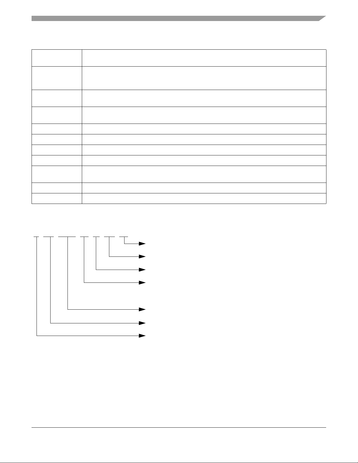
S FR 4310 J1 M AE 40
Speed Option
Temperature Option
Device Title
Controller Family
Qualification
Package Option
40 = 40 MHz
AE = 64-pin Lead Free/Halide Free LQFP
M = -40
o
C to +125oC
S = Maskset specific part number
Maskset Identifier First character usually identifies wafer fab
Second character usually identifiesSuffix
mask revision
active-high Names of signals that are active-high are shown in upper case text, without a # symbol at the end.
Active-high signals are asserted (active) when they are high and deasserted when they are low.
active-low An active-low signal is asserted (active) when it is at the logic low level and is deasserted when it is at the
logic high level.
Note: A # symbol at the end of a signal name indicates that the signal is active-low.
asserted A signal that is asserted is in its active logic state. An active-low signal changes from high to low when
asserted; an active-high signal changes from low to high when asserted.
deasserted A signal that is deasserted is in its inactive logic state. An active-low signal changes from low to high when
deasserted; an active-high signal changes from high to low when deasserted.
set To set a bit means to establish logic level one on the bit.
clear To clear a bit means to establish logic level zero on the bit.
0x0F The prefix 0x denotes a hexadecimal number.
0b0011 The prefix 0b denotes a binary number.
x In certain contexts, such as a signal encoding, this indicates don’t care. For example, if a field is binary
encoded 0bx001, the state of the most significant bit is don’t care.
== Used in equations, this symbol signifies comparison.
# A # symbol at the end of a signal name indicates that the signal is active-low.
Table 1-2. Notational Conventions
1.4 Part Number Coding
Figure 1-1. Order Part Number Coding
MFR4310 Reference Manual, Rev. 2
Freescale Semiconductor 27
Page 28

Introduction
MFR4310 Reference Manual, Rev. 2
28 Freescale Semiconductor
Page 29

Chapter 2 Device Overview
2.1 Introduction
The MFR4310 FlexRay Communication Controller implements the FlexRay protocol according to the
FlexRay Communications System Protocol Specification V2.1A.
The controller host interface (CHI) of the MFR4310 FlexRay Communication Controller is implemented
in accordance with Chapter 3, “FlexRay Module (FLEXRAYV4)” of this reference manual.
2.2 Features
The MFR4310 FlexRay controller provides the following features:
• Single channel support
— Internal channel A and FlexRay Port A can be configured to be connected to physical FlexRay
channel A or physical FlexRay channel B
• Variable bit rate support: 2.5, 5, 8, or 10 Mb/s
• 128 configurable message buffers with
— Individual frame ID filtering
— Individual channel ID filtering
— Individual cycle counter filtering
• Message buffer header, status and payload data are stored in FlexRay memory
— Consistent data access ensured by means of buffer locking scheme
— Host can lock multiple buffers at the same time
• Size of message buffer data section configurable from 0 up to 254 bytes
• Two independent message buffer segments with configurable size of payload data section
— Each segment can contain message buffers assigned to the static segment and message buffers
assigned to the dynamic segment at the same time
• Zero padding for transmit message buffers in static segment
— Applied when the frame payload length exceeds the size of the message buffer data section
• Transmit message buffers configurable with state/event semantics
• Message buffers can be configured as
— Receive message buffers
— Single buffered transmit message buffer
— Double buffered transmit message buffer (combines two single buffered message buffer)
• Individual message buffer reconfiguration supported
— Means provided to safely disable individual message buffers
— Disabled message buffers can be reconfigured
MFR4310 Reference Manual, Rev. 2
Freescale Semiconductor 29
Page 30

Device Overview
• Two independent receive FIFOs
— One receive FIFO per channel
— Up to 256 entries for each FIFO
— Global frame ID filtering, based on both value/mask filters and range filters
— Global channel ID filtering
— Global message ID filtering for the dynamic segment
• Four configurable slot error counters
• Four dedicated slot status indicators
— Used to observe slots without using receive message buffers
• Provides measured value indicators for clock synchronization
— PE internal synchronization frame ID and measurement tables can be copied into the FlexRay
memory
• Fractional macroticks are supported for clock correction
• Maskable interrupt sources provided through individual and combined interrupt lines
• One absolute timer
• One timer that can be configured to absolute or relative
Features specific to the MFR4310 include the following:
• Identical pinout to MFR4300; pin functionality compatible with MFR4300
• Three hardware selectable host interfaces:
— HCS12 Interface for direct connection to Freescale’ s HCS12 family of microcontrollers, with
interface clock signal to synchronize the data transfer (the maximum frequency of this clock
signal can be calculated from the ECLK_CC pulse width low and high times, t
LEC
and t
given in Table A-15.)
— Asynchronous Memory Interface (AMI) for asynchronous connection to microcontrollers —
minimum read access time of 56 ns (with CHICLK_CC running at 76 MHz)
— MPC Interface for asynchronous connection to Freescale’s MPC5xx and MPC55xx family
microcontrollers — minimum read access time of 56 ns (with CHICLK_CC running at
76 MHz)
• 8K bytes addressable for byte or word accesses
• Internal quartz oscillator of 40 MHz
• CHI and AMI/MPC clock selectable between 40 MHz oscillator clock used for PE and 20 MHz to
76 MHz separate CHI/AMI/MPC-only clock
• Internal voltage regulator for the digital logic and the oscillator
• Hardware selectable clock output to drive external host devices: disabled, 4, 10, or 40 MHz
• Maskable interrupt sources available over one interrupt output line
HEC
• RESET# glitch filter
• Electrical physical layer interface compatible with dedicated FlexRay physical layer
• Four multiplexed debug strobe pins
MFR4310 Reference Manual, Rev. 2
30 Freescale Semiconductor
Page 31

2.3 Block Diagram
Voltage Regulator
VSSR
VDDA
VSSA
VDDR
VSS2_5
VDD2_5
Oscillator
Clock and Reset
Gen. Module
RESET#
External
Clock Interface
CLKOUT/TM0
D0/PA7
D1/PA6
D2/PA5
D3/PA4
D4/PA3
D5/PA2
D6/PA1
D7/PA0
D8/PB7
D9/PB6
D10/PB5
D11/PB4
D12/PB3
D13/PB2
D14/PB1
D15/PB0
External
Bus Interface
AMI
HCS12
Interface
A1/XADDR19
A2/XADDR18
A3/XADDR17
A4/XADDR16
A5/XADDR15
A6/XADDR14
A7
A8
A9
OE#/ACS0
A11/ACS1
A12/ACS2
WE#/RW_CC#
CE#/LSTRB
A10/ECLK_CC
INT_CC#
Receiver A
Receiver B
RXD_BG2
RXD_BG1
Transmitter A Transmitter B
TXD_BG1/IF_SEL1
TXEN1#
TXD_BG2/IF_SEL0
TXEN2#
DBG3/CLK_S1
TCU Debug
TEST
VDDX[1:4]
VSSX[1:4]
XTAL
EXTAL/CLK_CC
VDDOSC
VSSOSC
BSEL0#/DBG1
BSEL1#/DBG0
DBG2/CLK_S0
CHICLK_CC
FlexRay Module
Device Overview
Figure 2-1. MFR4310 Functional Block Diagram
Freescale Semiconductor 31
MFR4310 Reference Manual, Rev. 2
Page 32

Device Overview
2.3.1 Memory Map
Table 2-1 shows the MFR4310 device memory map.
Table 2-1. MFR4310 Device Memory Map After Reset
address (Hex) Module Registers
1
0x0000–0x000E FlexRay
Configuration and Control Registers 16
Size
(bytes)
0x0010–0x0012 FlexRay Reserved 4
0x0014–0x0026 FlexRay Interrupt and Error Handling Registers 20
0x0028–0x003E FlexRay Protocol Status Registers 24
0x0040–0x0044 FlexRay Sync Frame Counter and Table Registers 6
0x0046–0x004A FlexRay Sync Frame Filter Registers 6
0x004C–0x0058 FlexRay Network Management Vector Registers 14
0x005A–0x0062 FlexRay Timer Configuration Registers 10
0x0064–0x0066 FlexRay Slot Status Configuration Registers 4
0x0068–0x007E FlexRay Slot Status and Slot Status Counter Registers 24
0x0080–0x0082 FlexRay MTS Generation Registers 4
0x0084 FlexRay Shadow Buffer Configuration Register 2
0x0086–0x008A FlexRay Receive FIFO — Configuration 6
0x008C–0x008E FlexRay Receive FIFO — Status 4
0x0090–0x009A FlexRay Receive FIFO — Filter 12
0x009C, 0x009E FlexRay Dynamic Segment Status Registers 4
0x00A0–0x00DE FlexRay Protocol Configuration Registers 64
0x00E0–0x00E2 CRG
2
Clock and Reset Generation Registers 4
0x00E4–0x00EE FlexRay Reserved 12
0x00F0–0x00FE PIM
3
Part ID, ASIC Version Number, and Interface Pin Drive Strength and
Pullup/pulldown Control and Enable Registers
0x0100–0x01FE FlexRay Message Buffers Configuration, Control, Status (Message Buffer 0–31) 256
0x0200–0x02FE FlexRay Message Buffers Configuration, Control, Status (Message Buffer 32–63) 256
0x0300–0x03FE FlexRay Message Buffers Configuration, Control, Status (Message Buffer 64–95) 256
0x0400–0x04FE FlexRay Message Buffers Configuration, Control, Status (Message Buffer 96–127) 256
0x0500–0x07FE FlexRay Reserved 768
0x0800–0x1FFE FlexRay Message Buffers and FIFO Frame Header/Offset/Status/Data 6144
1
For detailed information on the MFR4310 FlexRay module registers, see Chapter 3, “FlexRay Module (FLEXRAYV4).
2
For detailed information on the MFR4310 CRG module registers, see Chapter 6, “Clocks and Reset Generator (CRG)”.
3
For detailed information on the MFR4310 PIM module registers, see Chapter 4, “Port Integration Module (PIM)”.
MFR4310 Reference Manual, Rev. 2
16
32 Freescale Semiconductor
Page 33

Device Overview
2.3.2 Part ID and Module Version Number Assignments
Three 16-bit read-only registers provide information about the device and the MFR4310 FlexRay module
(see Table 2-2).
Table 2-2. Part ID and Module Version Numbers
Part ID
Device Mask Set Number
PIDR AVNR MVR
MFR4310 0M63J 4310 0000 8566
MFR4310 1M63J 4310 0001 8566
The PIDR (see Section 4.3.1.1, “Part ID Register (PIDR)”) provides the part ID number in binary coded
decimal.
The AVNR (see Section 4.3.1.2, “ASIC Version Number Register (AVNR)”) provides the ASIC version
number in binary coded decimal.
The MVR (see Section 3.3.2.3, “Module V ersion Register (MVR)”) provides the FlexRay module version
number in binary coded decimal. Bits 15 to 8 of the MVR comprise the controller host interface (CHI)
version number; bits 7 to 0 comprise the protocol engine (PE) version number.
These read-only values provide a unique ID for each revision of the device.
2.4 Signal Descriptions
2.4.1 System Pinout
The MFR4310 is available in a 64-pin low profile quad flat package (LQFP). Most pins perform two
functions, as described in Section 2.4.2, “Pin Functions and Signal Properties”. Figure 2-2 shows the pin
assignments.
NOTE
For a recommended printed circuit board layout, see Appendix C, “Printed
Circuit Board Layout Recommendations”.
MFR4310 Reference Manual, Rev. 2
Freescale Semiconductor 33
Page 34

Device Overview
1
2
3
4
5
6
7
8
9
10
11
12
13
14
15
16
171819202122232425262728293031
32
33
34
35
36
37
38
39
40
41
42
43
44
45
46
47
48
49
50
51
52
53
54
55
56
57
58
59
60
61
62
63
64
TEST
D9/PB6
D10/PB5
D11/PB4
D12/PB3
D13/PB2
D14/PB1
D15/PB0
VDDX1
VSSX1
A1/XADDR19
A2/XADDR18
A3/XADDR17
A4/XADDR16
A5/XADDR15
RESET#
INT_CC#
CLKOUT
D8/PB7
D7/PA0
VSS2_5
VDD2_5
D6/PA1
D5/PA2
D4/PA3
D3/PA4
VDDX3
A10/ECLK_CC
D2/PA5
VDDA
VSSA
VSSX3
BSEL1#/DBG0
BSEL0#/DBG1
DBG3/CLK_S1
TXD_BG2/IF_SEL0
TXEN2#
RXD_BG2
DBG2/CLK_S0
TXD_BG1/IF_SEL1
D1/PA6
D0/PA7
VSSX2
VDDX2
TXEN1#
VDDX4
A12/ACS2
RXD_BG1
CHICLK_CC
XTAL
VSSOSC
A9
A8
VDDR
VSSR
A7
A6/XADDR14
EXTAL/CLK_CC
VDDOSC
OE#/ACS0
A11/ACS1
CE#/LSTRB
WE#/RW_CC#
VSSX4
Figure 2-2. MFR4310 Pin Assignment
MFR4310 Reference Manual, Rev. 2
34 Freescale Semiconductor
Page 35

2.4.2 Pin Functions and Signal Properties
Table 2-3. Pin Functions and Signal Properties
Device Overview
Pin
#
11 A1 XADDR19 VDDX I PC - AMI/MPC address bus;
12 A2 XADDR18 VDDX I PC - AMI/MPC address bus;
13 A3 XADDR17 VDDX I PC - AMI/MPC address bus;
14 A4 XADDR16 VDDX I PC - AMI/MPC address bus;
15 A5 XADDR15 VDDX I PC - AMI/MPC address bus;
17 A6 XADDR14 VDDX I PC - AMI/MPC address bus;
18 A7 - VDDX I PC - AMI/MPC address bus
21 A8 - VDDX I PC - AMI/MPC address bus
Pin Name
Function 1 Function 2
1
Powered
by
I/O
Pin
2, 3
Type
Host Interface Pins
Reset Functional Description
HCS12 expanded address lines.
A1 is the LSB of the AMI/MPC address bus; XADDR14
is the LSB of the HCS12 expanded address lines
HCS12 expanded address lines.
HCS12 expanded address lines.
HCS12 expanded address lines.
HCS12 expanded address lines.
HCS12 expanded address lines.
22 A9 - VDDX I PC - AMI/MPC address bus
27 OE# ACS0 VDDX I PC - AMI/MPC read output enable signal;
HCS12 address select input
28 A11 ACS1 VDDX I PC - AMI/MPC address bus;
HCS12 address select inputs
34 A12 ACS2 VDDX I PC - AMI/MPC address bus;
HCS12 address select inputs
48 BSEL1# DBG0 VDDX I/O PC - AMI/MPC byte select;
Debug strobe point
47 BSEL0# DBG1 VDDX I/O PC - AMI/MPC byte select;
Debug strobe point
10 D15 PB0 VDDX I/O Z/DC/PC Z AMI/MPC data bus;
HCS12 multiplexed address/data bus.
D15 is the MSB of the AMI/MPC data bus; PB0 is the
LSB of the HCS12 address/data bus
7 D14 PB1 VDDX I/O Z/DC/PC Z AMI/MPC data bus;
HCS12 multiplexed address/data bus
6 D13 PB2 VDDX I/O Z/DC/PC Z AMI/MPC data bus;
HCS12 multiplexed address/data bus
MFR4310 Reference Manual, Rev. 2
Freescale Semiconductor 35
Page 36

Device Overview
Table 2-3. Pin Functions and Signal Properties (continued)
Pin
#
Pin Name
Function 1 Function 2
1
Powered
by
I/O
Pin
Type
Reset Functional Description
2, 3
5 D12 PB3 VDDX I/O Z/DC/PC Z AMI/MPC data bus;
HCS12 multiplexed address/data bus
4 D11 PB4 VDDX I/O Z/DC/PC Z AMI/MPC data bus;
HCS12 multiplexed address/data bus
3 D10 PB5 VDDX I/O Z/DC/PC Z AMI/MPC data bus;
HCS12 multiplexed address/data bus
2 D9 PB6 VDDX I/O Z/DC/PC Z AMI/MPC data bus;
HCS12 multiplexed address/data bus
62 D8 PB7 VDDX I/O Z/DC/PC Z AMI/MPC data bus;
HCS12 multiplexed address/data bus
61 D7 PA0 VDDX I/O Z/DC/PC Z AMI/MPC data bus;
HCS12 multiplexed address/data bus
58 D6 PA1 VDDX I/O Z/DC/PC Z AMI/MPC data bus;
HCS12 multiplexed address/data bus
57 D5 PA2 VDDX I/O Z/DC/PC Z AMI/MPC data bus;
HCS12 multiplexed address/data bus
56 D4 PA3 VDDX I/O Z/DC/PC Z AMI/MPC data bus;
HCS12 multiplexed address/data bus
55 D3 PA4 VDDX I/O Z/DC/PC Z AMI/MPC data bus;
HCS12 multiplexed address/data bus
51 D2 PA5 VDDX I/O Z/DC/PC Z AMI/MPC data bus;
HCS12 multiplexed address/data bus
40 D1 PA6 VDDX I/O Z/DC/PC Z AMI/MPC data bus;
HCS12 multiplexed address/data bus
39 D0 PA7 VDDX I/O Z/DC/PC Z AMI/MPC data bus;
HCS12 multiplexed address/data bus.
D0 is the LSB of the AMI data bus; PA7 is the MSB of
the HCS12 address/data bus
29 CE# LSTRB VDDX I PC - AMI/MPC chip select signal;
HCS12 low-byte strobe signal
30 WE# RW_CC# VDDX I PC - AMI write enable signal;
HCS12 read/write select signal
52 A10 ECLK_CC VDDX I PC - AMI/MPC address bus;
HCS12 clock input
Physical Layer Interface
33 RXD_BG1 - VDDX I PC - PHY Data receiver input
43 RXD_BG2 - VDDX I PC - PHY Data receiver input
36 TXEN1# - VDDX O DC 1 T ransmit enable for PHY
MFR4310 Reference Manual, Rev. 2
36 Freescale Semiconductor
Page 37

Table 2-3. Pin Functions and Signal Properties (continued)
Device Overview
Pin
#
Pin Name
Function 1 Function 2
1
Powered
by
I/O
Pin
Type
Reset Functional Description
2, 3
44 TXEN2# - VDDX O DC 1 T ransmit enable for PHY
45 TXD_BG2 IF_SEL0 VDDX I/O DC/PU - PHY Data transmitter output / Host interface select
41 TXD_BG1 IF_SEL1 VDDX I/O DC/PD - PHY Data transmitter output / Host interface select
Clock Signals
32 CHICLK_CC - VDDX I - - External CHI clock input – selectable
63 CLKOUT - VDDX I/O DC - Controller clock output – selectable as disabled/4/10/40
MHz
Others
16 RESET# - VDDX I PD - External hardware reset input
64 INT_CC# - VDDX O OD/DC 0 Controller level-sensitive interrupt output
1 TEST - VDDX I PD - Factory T e st mode select – must be tied to logic low in
application
42 DBG2 CLK_S0 VDDX I/O DC/PD - Debug strobe point / Output clock select
46 DBG3 CLK_S1 VDDX I/O DC/PD - Debug strobe point / Output clock select
Oscillator
24 EXTAL CLK_CC VDDOSC I - - Crystal driver / External clock
25 XTAL - - I - - Crystal driver
Supply/Bypass Filter pins
8 VDDX1 - - - - - Supply voltage, I/O
37 VDDX2 - - - - - Supply voltage, I/O
54 VDDX3 - - - - - Supply voltage, I/O
35 VDDX4 - - - - - Supply voltage, I/O
9 VSSX1 - - - - - Supply voltage ground, I/O
38 VSSX2 - - - - - Supply voltage ground, I/O
53 VSSX3 - - - - - Supply voltage ground, I/O
31 VSSX4 - - - - - Supply voltage ground, I/O
20 VDDR - - - - - Supply voltage, supply to pin drivers and internal
Voltage Regulator
19 VSSR - - - - - Supply voltage ground, ground to pin drivers and
internal Voltage Regulator
50 VDDA - - - - - Supply analog voltage
49 VSSA - - - - - Supply analog voltage ground
MFR4310 Reference Manual, Rev. 2
Freescale Semiconductor 37
Page 38

Device Overview
Table 2-3. Pin Functions and Signal Properties (continued)
Pin
#
59 VDD2_5
60 VSS2_5
26 VDDOSC4- - - - - Oscillator voltage power supply output (nominally 2.5V)
23 VSSOSC
1
# – signal is active-low
2
Acronyms:
PC – (Pullup/pulldown Controlled) Register controlled internal weak pullup/pulldown for a pin in the input mode. Refer to the
following sections for more information:
– Section 4.3.1.5, “Host Interface Pins Pullup/pulldown Enable Register (HIPPER)”
– Section 4.3.1.6, “Host Interface Pins Pullup/pulldown Control Register (HIPPCR)”
– Section 4.3.1.7, “Physical Layer Pins Pullup/pulldown Enable Register (PLPPER)”
– Section 4.3.1.8, “Physical Layer Pins Pullup/pulldown Control Register (PLPPCR)”
PU/PD – (Pullup/Pulldown) Internal weak pullup/pulldown for a pin in the input mode
DC – (Drive strength Controlled) Register controlled drive strength for a pin in the output mode. Refer to the following sections
for more information:
– Section 4.3.1.3, “Host Interface Pins Drive Strength Register (HIPDSR)”
– Section 4.3.1.4, “Physical Layer Pins Drive Strength Register (PLPDSR)”
Z – Tristated pin
OD – (Open Drain) Output pin with open drain
3
Reset state:
All pins with the PC option – pullup/pulldown is disabled,
all pins with the DC option – have full drive strength
4
No load allowed except for bypass capacitors.
Pin Name
Function 1 Function 2
4
4
4
1
- - - - - Core voltage power supply output (nominally 2.5V)
- - - - - Core voltage ground output
- - - - - Oscillator voltage ground output
Powered
by
I/O
Pin
Type
Reset Functional Description
2, 3
2.4.3 Detailed Signal Descriptions
2.4.3.1 A[6:1]/XADDR[14:19] — AMI/MPC Address Bus; HCS12 Expanded
Address Inputs
A[6:1]/XADDR[14:19] are general purpose input pins. Their function is selected by the IF_SEL[1:0] pins.
Refer to Section 2.7, “External Host Interface” for more information. The pins can be configured to enable
or disable pullup or pulldown resistors on the pins. (See Section 4.3.1.5, “Host Interface Pins
Pullup/pulldown Enable Register (HIPPER)” and Section 4.3.1.6, “Host Interface Pins Pullup/pulldown
Control Register (HIPPCR)”.)
A[6:1] are AMI/MPC interface address signals. A1 is the LSB of the AMI/MPC address bus.
XADDR[14:19] are HCS12 interface expanded address lines. XADDR14 is the LSB of the HCS12
interface expanded address lines.
MFR4310 Reference Manual, Rev. 2
38 Freescale Semiconductor
Page 39

Device Overview
2.4.3.2 A[9:7] — AMI/MPC Address Bus
A[9:7] are general purpose input pins. Their function is selected by the IF_SEL[1:0] pins. Refer to
Section 2.7, “External Host Interface” for more information. The pins can be configured to enable or
disable pullup or pulldown resistors on the pins.
A[9:7] are AMI/MPC interface address signals.
2.4.3.3 OE#/A CS0 — AMI/MPC Read Output Enable, HCS12 Address Select Input
OE#/ACS0 is a general purpose input pin. Its function is selected by the IF_SEL[1:0] pins. Refer to
Section 2.7, “External Host Interface” for more information. The pin can be configured to enable or
disable a pullup or pulldown resistor on the pin.
OE# is the AMI/MPC interface output enable signal. This signal controls MFR4310 data output and the
state of three-stated data pins D[15:0] during host read operations.
ACS0 is an HCS12 interface address select signal.
2.4.3.4 A[12:11]/ACS[2:1] — AMI/MPC Address Bus, HCS12 Expanded Address
Inputs
A[12:11]/ACS[2:1] are general purpose input pins. Their function is selected by the IF_SEL[1:0] pins.
Refer to Section 2.7, “External Host Interface” for more information. The pins can be configured to enable
or disable pullup or pulldown resistors on the pins.
A[12:11] are AMI/MPC interface address signals.
ACS[1:2] are HCS12 interface address select signals.
2.4.3.5 BSEL[1:0]#/DBG[0:1] — AMI/MPC Byte Select, Debug Strobe Points
BSEL[1:0]#/DBG[0:1] are general purpose input or output pins. Their function is selected by the
IF_SEL[1:0] pins. Refer to Section 2.7, “External Host Interface” for more information. The pins can be
configured to provide high or reduced output drive, and also to enable or disable pullup or pulldown
resistors on the pins.
BSEL[1:0]# are AMI/MPC byte select signals.
DBG[0:1] are debug strobe point output signals. The functions output on these pins are selected by the
debug port control register. Refer to Section 3.4.16, “Strobe Signal Support” for more information.
2.4.3.6 D[15:8]/PB[0:7] — AMI/MPC Data Bus, HCS12 Multiplexed Address/Data
Bus
D[15:8]/PB[0:7] are general purpose input or output pins. Their functions are selected by the IF_SEL[1:0]
pins. Refer to Section 2.7, “External Host Interface” for more information. These pins can be configured
to provide high or reduced output drive, and also to enable or disable pullup or pulldown resistors on the
pins.
MFR4310 Reference Manual, Rev. 2
Freescale Semiconductor 39
Page 40

Device Overview
D[15:8] are data signals of the AMI/MPC interface. D15 is the MSB of the AMI/MPC data bus.
PB[0:7] are HCS12 interface multiplexed address/data signals in the HCS12 Host interface mode of
operation. PB0 is the LSB of the HCS12 address/data bus.
2.4.3.7 D[7:0]/PA[0:7] — AMI/MPC Data Bus, HCS12 Multiplexed Address/Data
Bus
D[7:0]/PA[0:7] are general purpose input or output pins. Their functions are selected by the IF_SEL[1:0]
pins. Refer to Section 2.7, “External Host Interface” for more information. These pins can be configured
to provide high or reduced output drive, and also to enable or disable pullup or pulldown resistors on the
pins.
D[7:0] are data signals of the AMI/MPC interface. D0 is the LSB of the AMI/MPC data bus.
PA[0:7] are HCS12 interface multiplexed address/data signals in the HCS12 Host interface mode of
operation. PA7 is the MSB of the HCS12 address/data bus.
2.4.3.8 CE#/LSTRB — AMI/MPC Chip Select, HCS12 Low-byte Strobe
The function of this pin is selected by IF_SEL[1:0] pins. Refer Section 2.7, “External Host Interface” for
more information. The pin can be configured to enable or disable a pullup or pulldown resistor on the pin.
CE# is an AMI/MPC interface transfer size input signal. It indicates the size of the requested data transfer
in the current bus cycle.
LSTRB is an HCS12 interface low-byte strobe input signal. It indicates the type of bus access.
2.4.3.9 WE#/RW_CC# — AMI Write Enable, HCS12 R ead/Write Select
The function of this pin is selected by the IF_SEL[1:0] pins. Refer to Section 2.7, “External Host
Interface” for more information. The pin can be configured to enable or disable a pullup or pulldown
resistor on the pin.
WE# is an AMI interface write select signal. It strobes the valid data provided by the host on the D[15:0]
pins during write operations to the MFR4310 memory.
RW_CC# is an HCS12 interface read/write input signal. It indicates the direction of data transfer for a
transaction.
2.4.3.10 A10/ECLK_CC — AMI/MPC Address Bus, HCS12 Clock Input
The function of this pin is selected by the IF_SEL[1:0] pins. Refer Section 2.7, “External Host Interface”
for more information. The pin can be configured to enable or disable a pullup or pulldown resistor on the
pin.
A10 is an AMI/MPC interface address signal.
ECLK_CC is the HCS12 interface clock input signal. (The maximum frequency of this signal can be
calculated from the ECLK_CC pulse width low and high times, t
MFR4310 Reference Manual, Rev. 2
40 Freescale Semiconductor
LEC
and t
given in Table A-15.)
HEC
Page 41

Device Overview
2.4.3.11 RXD_BG[2:1] — PHY Data Receiver Inputs
RXD_BG[2:1] are bus driver receive data input signals if the FlexRay Optical/Electrical PHY is
configured:
• RXD_BG1 is the input to the CC from Physical Layer Channel 1
• RXD_BG2 is the input to the CC from Physical Layer Channel 2
These pins can be configured to enable or disable pullup or pulldown resistors on the pins.
2.4.3.12 TXEN[2:1]# — PHY Transmit Enable
TXEN[2:1]# are bus driver transmit enable output signals if the FlexRay Optical/Electrical PHY is
configured:
• TXEN1# is the output of the CC to Physical Layer Channel 1
• TXEN2# is the output of the CC to Physical Layer Channel 2
These pins can be configured to provide high or reduced output drive.
2.4.3.13 TXD_BG[1:2]/IF_SEL[1:0] — PHY Transmit Data Outputs, Host Interface
Selection
These pins can be configured to provide high or reduced output drive.
TXD_BG[1:2] are bus driver transmit data output signals if the FlexRay Optical/Electrical PHY is
configured:
• TXD_BG1 is the output of the CC to Physical Layer Channel 1
• TXD_BG2 is the output of the CC to Physical Layer Channel 2
IF_SEL[1:0] are the CC external interface selection input signals. Refer to Table 2-6 for the selection
coding.
NOTE
The IF_SEL[1:0] signals are inputs during the internal reset sequence and
are latched during the internal reset sequence.
While the IF_SEL[1:0] levels are being latched, the output drive control is
disabled and the internal pull resistors are connected (pullup on IF_SEL0;
pulldown on IF_SEL1).
As IF_SEL[1:0] signals share pins with Physical Layer Interface signals,
pullup/pulldown devices must be used for the selection. Recommended
pullup/pulldown resistor values for the IF_SEL[1:0] inputs are given in
Section 2.6.3, “Recommended Pullup/pulldown Resistor Values”.
2.4.3.14 CHICLK_CC — External CHI Clock Input
CHICLK_CC is the selectable external CHI clock input. It can be selected to drive the Asynchronous
Memory Interface (see Section 2.6.2, “External Host Interface Selection”).
MFR4310 Reference Manual, Rev. 2
Freescale Semiconductor 41
Page 42

Device Overview
2.4.3.15 CLKOUT — Clock Output
CLKOUT is a continuous clock output signal. The frequency of CLKOUT is selected by the CLK_S[1:0]
pins. The CLKOUT signal, if enabled, is always active:
1. after power-up of the CC,
2. after a low-voltage reset,
3. after a clock monitor failure reset,
4. during and after an external hard reset.
The pin can be configured to provide high or reduced output drive.
NOTE
As the CLKOUT signal can be disabled during internal resets, refer to
Section 6.4.3, “CLKOUT Mode Selection and Control” for more
information on CLKOUT generation during external hard and internal
resets.
2.4.3.16 RESET# — External Reset
RESET# is an active-low control signal that acts as an input to initialize the CC to a known startup state.
The RESET# pin is pulled down internally.
NOTE
The CRG has a built-in RESET# glitch filter to prevent glitches on the
RESET# pin from resetting the device (see Section 6.4.1.4, “RESET#
Glitch Filter”).
2.4.3.17 INT_CC# — Interrupt Output
INT_CC# is an AMI/MPC and HCS12 interfaces interrupt request output signal. The CC may request a
service routine from the host to run. The interrupt is indicated by the logic level: the interrupt is asserted
if the INT_CC# outputs a logic 0 and is deasserted if INT_CC# outputs a logic 1.
The pin can be configured to provide high or reduced output drive. This is an open-drain output.
2.4.3.18 TEST
The TEST pin is pulled down, internally, and must be tied to VSS in all applications.
2.4.3.19 DBG[3:2]/CLK_S[1:0] — Debug Strobe Points, Output Clock Select
DBG[3:2] are debug strobe point output signals. The functions output on these pins are selected by the
debug port control register. Refer to Section 3.4.16, “Strobe Signal Support” for more information.
NOTE
CLK_S[1:0] signals are inputs during the internal reset sequence and are
latched during the internal reset sequence.
MFR4310 Reference Manual, Rev. 2
42 Freescale Semiconductor
Page 43

Device Overview
Where:
• Q = 40 MHz crystal
• Rb is in the range 1M – 10 MΩ
• Rs is a lower value, which can be 0 Ω
•C1 = C2
• See crystal manufacturer’s product specification for
recommended values
Oscillator supply output capacitor C3 = 220 nF
MFR4310
XTAL
EXTAL
VDDOSC
VSSOSC
Q
C2
C1
Rb
Rs
VSSOSC
VSSOSC
C3
MFR4310
XTAL
EXTAL
VDDOSC
VSSOSC
VSSOSC
C3
Where:
G = 40 MHz CMOS-compatible External Oscillator
(VDDOSC-Level)
CLKOUT
G
Not connected
(left open)
While the CLK_S[1:0] levels are being latched, the output drive control is
disabled, and the internal pulldown resistors are connected to the pins.
2.4.3.20 EXTAL/CC_CLK — Crystal Driver, External Clock Pin
This pin can act as a crystal driver pin (EXT AL) or as an external clock input pin (CC_CLK). On reset, the
device clock is derived from the input frequency on this pin. Refer to Figure 2-3 for Pierce oscillator
connections and Figure 2-4 for external clock connections. See also Chapter 7, “Oscillator (OSCV2)”.
2.4.3.21 XTAL — Crystal Driver Pin
XTAL is a crystal driver pin. Refer to Figure 2-3 for oscillator connections and Figure 2-4 for external
clock connections. See also Chapter 7, “Oscillator (OSCV2)”.
Figure 2-3. Oscillator Connections
Freescale Semiconductor 43
Figure 2-4. External Square Wave Clock Generator Connection
MFR4310 Reference Manual, Rev. 2
Page 44

Device Overview
2.4.4 Power Supply Pins
MFR4310 power and ground pins are summarized in Table 2-4 and described below.
NOTE
All VSS pins must be connected together in the application.
Because fast signal transitions place high, short-duration current demands
on the power supply, use bypass capacitors with high-frequency
characteristics and place them as close to the MFR4310 as possible. Bypass
requirements depend on how heavily the MFR4310 pins are loaded.
Table 2-4. MFR4310 Power and Ground Connection Summary
Pin Number
Mnemonic
64-pin LQFP
VDD2_5 59 2.5V Internal power and ground generated by internal regulator
VSS2_5 60 0V
VDDR 20 3.3V External power and ground, supply to supply to pin drivers and internal
VSSR 19 0V
VDDX[1:4] 8, 37, 54, 35 3.3V External power and ground, supply to pin drivers.
VSSX[1:4] 9, 38, 53, 31 0V
VDDA 50 3.3V Operating voltage and ground for the internal voltage regulator.
VSSA 49 0V
VDDOSC 26 2.5V Provides operating voltage and ground for the internal oscillator. This
VSSOSC 23 0V
Nominal
Voltage
Description
voltage regulator.
allows the supply voltage to the oscillator to be bypassed independently.
Internal power and ground generated by internal regulator.
2.4.4.1 VDDX, VSSX — Power and Ground Pins for I/O Drivers
External power and ground for I/O drivers.
2.4.4.2 VDDR, VSSR — Power and Ground Pins for I/O Drivers and Internal
Voltage Regulator
External power and ground for I/O drivers and input to the internal voltage regulator.
NOTE
The VDDR pin enables the internal 3.3 V to 2.5 V voltage regulator. If this
pin is tied to ground, the internal voltage regulator is turned off.
MFR4310 Reference Manual, Rev. 2
44 Freescale Semiconductor
Page 45

Device Overview
2.4.4.3 VDD2_5, VSS2_5 — Core Power Pins
Power is supplied to the MFR4310 core through VDD2_5 and VSS2_5. This 2.5 V supply is derived from
the internal voltage regulator. No static load is allowed on these pins. If VDDR is tied to ground, the
internal voltage regulator is turned off.
NOTE
No load is allowed except for bypass capacitors.
2.4.4.4 VDDA, VSSA — Power Supply Pins for VREG
VDDA, VSSA are the power supply and ground input pins for the voltage regulator . They also provide the
reference voltages for the internal voltage regulator.
2.4.4.5 VDDOSC, VSSOSC — Power Supply Pins for OSC
VDDOSC, VSSOSC provide operating voltage and ground for the oscillator. This allows the supply
voltage to the oscillator to be bypassed independently. This 2.5 V voltage is generated by the internal
voltage regulator.
NOTE
No load is allowed except for bypass capacitors.
2.5 Modes of Operation
Refer to Section 3.1.6, “Modes of Operation” for full descriptions of the MFR4310 Disabled and Normal
modes of operation.
2.6 External Clock and Host Interface Selection
2.6.1 External 4/10/40 MHz Output Clock
A continuous external 4/10/40 MHz output clock signal is provided by the CC on the CLKOUT pin. See
Section 2.4.3.15, “CLKOUT — Clock Output” for details of when this signal is active.
The output frequency of the CLKOUT signal is selected by the CLK_S[1:0] input pins, in accordance with
Table 2-5:
Table 2-5. CLKOUT Frequency Selection
Pin
CLKOUT Function
CLK_S0 CLK_S1
0 0 4 MHz output
1
1 0 10 MHz output
MFR4310 Reference Manual, Rev. 2
Freescale Semiconductor 45
Page 46

Device Overview
Table 2-5. CLKOUT Frequency Selection
Pin
CLKOUT Function
CLK_S0 CLK_S1
0 1 40 MHz output
1 1 Disabled (CLKOUT output is “0“)
1
This is the default clock frequency selection (i.e. if no external pull
resistors are connected to CLK_S0 and CLK_S1, the internal pulldown
resistors on these pins take effect).
NOTE
As the CLK_S[1:0] signals are multiplexed with DBG[2:3], CLKOUT
should be selected using pullup and pulldown resistors
2.6.2 External Host Interface Selection
The MFR4310 can be connected and controlled by two types of interface through the CC EBI. Two pins,
IF_SEL0 and IF_SEL1, are used to configure the interface type, in accordance with Table 2-6.
Table 2-6. Interface Selection
Pin
Interface
IF_SEL0 IF_SEL1
0 0 MPC Interface CHICLK_CC 1
0 1 HCS12 Synchronous Interface CLK_CC 0
1 0 Asynchronous Memory Interface
1 1 Asynchronous Memory Interface CHICLK_CC 1
1
This is the default interface (i.e. if no external pull resistors are connected to IF_SEL0 and IF_SEL1, the
internal pullup on IF_SEL0 and the internal pul ldown on IF_SEL1 take effect).
CHI and Host
Interface Clock
1
CLK_CC 0
CRSR.ECS
The CC latches the values of the IF_SEL0 and IF_SEL1 signals, when it leaves an internal or external reset
state, and analyzes them to configure the interface for the type of exte rnal host. The CC does not analyze
them after it has left the reset state. For more information on the internal and external reset states, see
Chapter 6, “Clocks and Reset Generator (CRG)”.
NOTE
The internal pull devices on IF_SEL1 and IF_SEL0 are enabled only during
reset; they are disabled after the reset operation is complete.
NOTE
The following steps must be taken to select a correct external host interface
mode.
1. Set IF_SEL0, IF_SEL1 for MPC mode, HCS12 synchronous mode or AMI mode.
MFR4310 Reference Manual, Rev. 2
46 Freescale Semiconductor
Page 47

Device Overview
2. Assert the external hard reset signal of the CC again.
2.6.3 Recommended Pullup/pulldown Resistor Values
As the IF_SEL[1:0] signals share pins with Physical Layer Interface signals, pullup and pulldown resistors
should be used for the selection. The recommended pullup/pulldown resistor values for the IF_SEL[1:0]
inputs are given in Table 2-7:
Table 2-7. Recommended Pullup and Pulldown Resistor Values for IF_SEL[1:0] Inputs
IO, Regulator and analog supply le vel
(V
)
DD5
3.3V 16 47 k
5V 10 47 kΩ
1
The listed values are calculated for the MFR4310-Physical Layer connection where no internal pullup/pulldown
resistors are assumed in the Electrical PHY at the TXD_BG1 and TXD_BG2 interface lines. If an Electrical PHY
device has internal pullup/pulldown resistors connected to these signals, then the external pullup/pulldown resistor
values must be recalculated to ensure that V
resistors for the chosen V
are met. See Section A.1.9, “I/O Characteristics” for more details on VIL, VIH and V
DD5
Pullup resistor
requirements for pulldown resistors or VIH requirements for pullup
IL
1
Pulldown resistor
1
Units
Ω
.
DD5
2.7 External Host Interface
The MFR4310 can be connected through three types of bus interface (see Section 2.6.2, “External Host
Interface Selection” for information on how to select the host interface). The three types of microprocessor
interface are described below.
2.7.1 Asynchronous Memory Interface
Figure 2-5 shows how to connect the CC to a microcontroller using the AMI interface.
• Data exchange in AMI Mode is controlled by the CE#, WE# and OE# signals.
• The AMI interface is implemented as an asynchronous memory slave module, thus enabling fast
interfacing between the CC and a variety of microcontrollers.
• The AMI interface decodes its internal register addresses with the help of the chip select signal CE#
and the address lines A[12:1].
• The AMI interface accepts only aligned 16-bit read and 8-bit or 16-bit write transactions. The AMI
interface does not support 8-bit read accesses.
— The byte selects BSEL[1:0]#, the chip enable CE#, the output enable OE#, and the write enable
WE# are used to determine the type of access as shown in Table 2-8.
Table 2-8. AMI Access Types
CE# WE# OE# BSEL1# BSEL0# Type of Access
0 0 0 X X Illegal
0 0 1 0 0 16-bit wr ite to word address
0 0 1 0 1 8-bit write to even byte address
MFR4310 Reference Manual, Rev. 2
Freescale Semiconductor 47
1
2
Page 48

Device Overview
Table 2-8. AMI Access Types
CE# WE# OE# BSEL1# BSEL0# Type of Access
0 0 1 1 0 8-bit write to odd byte address
0 0 1 1 1 Illegal
0 1 1 X X no access
0 1 0 X X 16-bit read from word address
1 X X X X no access
1
Write data from D[15:8] to even byte address and from D[7:0] to odd byte address.
2
Write data from D[15:8].
3
Write data from D[7:0].
4
Read data from even byte address at D[15:8] and from odd byte address at D[7:0].
3
4
• WE# indicates the direction of data transfer for a transaction.
• OE# enables the AMI data output to a microcontroller during read transactions.
• INT_CC# is an interrupt line that can be used for requesting, by means of the internal interrupt
controller, a service routine from a host controller.
• The AMI interface does not support burst transactions.
NOTE
For the AMI, D0 is the LSB of the 16-bit data bus.
NOTE
If the AMI mode without the CHICLK_CC signal is selected (i.e.
IF_SEL[1:0] = 0b01), CHICLK_CC must be driven to logic 0 or logic 1 (it
must not be left floating).
MFR4310 Reference Manual, Rev. 2
48 Freescale Semiconductor
Page 49

2.7.1.1 Asynchronous Memory Interface with S12X Family
MFR4310
S12X Family
D0
D15 D15
D0
A1
A12 A12
A1
…
…
…
…
CE#
WE#
OE#
CSn
WE
RE
BSEL1#UDS
LDS BSEL0#
INT_CC#
TXD_BG2/IF_SEL0
TXD_BG1/IF_SEL1
IRQn
VDDXn
PL Interface
VSSXn
Device Overview
Freescale Semiconductor 49
Figure 2-5. AMI Interface with S12X Family
MFR4310 Reference Manual, Rev. 2
Page 50

Device Overview
MFR4310DSP56F83xx Family
D0
D15 D15
D0
A1
A11 A12
A0
…
…
…
…
WE#
CE#
OE#
WR#
CSn#
RD#
INT_CC#
TXD_BG2/IF_SEL0
TXD_BG1/IF_SEL1
IRQn#
VDDXn
PL Interface
VSSXn
BSEL1#
BSEL0#
2.7.1.2 Asynchronous Memory Interface with DSP 56F83 (Hawk) Family
Figure 2-6. AMI Interface with DSP 56F83 (Hawk) Family
2.7.1.3 Asynchronous Memory Interface Timing
See Section A.4, “Asynchronous Memory Interface Timing” for timing characteristics of the AMI
interface.
2.7.2 MPC Interface
Figure 2-7 shows how to connect the CC to a microcontroller using the MPC interface. In this case, the
host bus pins have the meanings shown in Table 2-9.
• Data exchange in MPC mode is controlled by the CE#, BSEL[1:0]#, and OE# inputs.
• The MPC interface is implemented as an asynchronous memory slave module, thus enabling the
fast interfacing with a variety of microcontrollers.
• The MPC interface decodes its internal register addresses with help of the chip select signal CE#
and the address lines A[12:1].
• The MPC interface accepts only aligned 16-bit read and 8- or 16-bit write transactions. The MPC
interface does not support 8-bit read accesses.
MFR4310 Reference Manual, Rev. 2
50 Freescale Semiconductor
Page 51

Device Overview
— The chip enable CE#, the output enable OE#, and the write enables BSEL[1:0]# are used to
determine the type of access as shown in Table 2-8.
Table 2-9. MPC Interface Access Types
CE# OE# BSEL1# BSEL0# Type of Access
0 0 X 0 illegal
0 0 0 X illegal
0 0 1 1 16-bit read from word address
0 1 0 0 16-bit write to word address
0 1 0 1 8-bit write to even byte address
0 1 1 0 8-bit write to odd byte address
0 1 1 1 no access
1 X X X no access
1
Read data from even byte address at D[15:8] and from odd byte address at
D[7:0].
2
Write data from D[15:8] to even byte address and from D[7:0] to odd byte
address.
3
Write data from D[15:8].
4
Write data from D[7:0].
1
2
3
4
• BSEL[1:0]# inputs indicate the direction of the data transfer for a transaction.
• OE# input enables the MPC data output during read transactions.
NOTE
D0 is the LSB of the 16-bit data bus.
MFR4310 Reference Manual, Rev. 2
Freescale Semiconductor 51
Page 52

Device Overview
MFR4310
MPC5xx Family
D0
DATA0 D15
DATA15
A1
ADDR19 A12
ADDR30
…
…
…
…
CE#
OE#
CSn#
OE#
INT_CC#
TXD_BG2/IF_SEL0
TXD_BG1/IF_SEL1
IRQn#
VDDXn
VSSXn
PL Interface
WE0/BE0
WE1/BE1
BSEL1#
BSEL0#
MPC55xx Family
2.7.2.1 MPC Interface with MPC5xx and MPC55xx Families
Figure 2-7. MPC EBI Interface with MPC5xx and MPC55xx Families
2.7.2.2 MPC Interface Timing
See Section A.5, “MPC Interface Timing” for timing characteristics of the MPC interface.
2.7.3 HCS12 Interface
Chip selection for the HCS12 interface is generated internally using the following signals (see Figure 2-8):
• The input values of the expanded address signals XADDR[14:19] are compared with logical 0’s
• The three most significant bits of the demultiplexed address bus, PA[5:7], are compared with the
(the HCS12 External Bus Interface (EBI) is in the Paged or Unpaged mode).
pattern set up externally on the address chip select pins ACS[0:2]; PA5 is compared with ACS0,
PA6 with ACS1, PA7 with ACS2.
NOTE
The address decoding phase of a read/write operation is passed if all the
comparisons described above are passed.
MFR4310 Reference Manual, Rev. 2
52 Freescale Semiconductor
Page 53

Device Overview
Figure 2-9 shows how to connect the CC to an HCS12 MCU with EBI paged mode support.
Figure 2-10 shows how to connect he CC to an HCS12 MCU with EBI unpaged mode support.
• The HCS12 interface supports the paged and the unpaged modes of the HCS12 External Bus
Interface connected to it.
• The HCS12 interface is implemented as an synchronous HCS12 External Bus slave module, thus
enabling the fast data exchange between them.
• The HCS12 interface decodes the addresses of read/write transactions to its internal registers, and
generates its internal chip select signal, CS, using the address/data lines PA[0:7], PB[0:7],
ACS[0:2], and XADDR[14:19]:
— The address and data lines PA[0:7], PB[0:7] are multiplexed. They are denoted ADR[0:15]
when referring to the address, and DAT A[0:15] when referring to the data. The FlexRay CC is
selected only when the address ADR[13:15] matches ACS[0:2] (ADR13 matches ACS0,
ADR12 matches ACS1, etc.) and the address XADDR[14:19] matches 0.
• The HCS12 interface accepts only aligned 16-bit read and 8-bit or 16-bit write transactions. The
HCS12 interface does not support 8-bit read accesses.
— The internal chip select, CS, the low byte strobe, LSTRB, the least significant bit of the address,
ADR0, and the read/write select, R W_CC#, are used to determine the type of access, as shown
in Table 2-10.
Table 2-10. HCS12 Access Types
CS RW_CC# LSTRB ADR0 Type of Access
0 X X X No access
1 0 0 0 16-bit write to word address
1 0 0 1 8-bit write to an odd address
1 0 1 0 8-bit write to an even address
1011Not supported
1 1 0 0 16-bit read from an even address
1101Not supported
1110Not supported
1111Not supported
1
Write data from PA to even byte address and from PB to odd byte address.
2
Write data from PB.
3
Read data from even byte address at PA and from odd byte address at PB.
1
2
2
3
• RW_CC# indicates the direction of data transfer for a transaction.
• INT_CC# is an interrupt line that can be used for requesting, by means of the internal interrupt
controller, a service routine from the HCS12 device.
MFR4310 Reference Manual, Rev. 2
Freescale Semiconductor 53
Page 54

Device Overview
16 bit
Address
/Data
Multi-
plexer
16 bit
16 bit
10 bit
3 bit
3 bit
6 bit
6 bit
2 bit
2 bit
&
1
0
1
000000
01
DATA[0:15]
DATA SIGNALS
ADR[0:15]
ADDRESS SIGNALS
ADR[0:9]
ADDRESS SIGNALS
CS
PA[0:7]
ACS[0:2]
XADDR[14:19]
ACS[0:2]
XADDR[14:19]
ADR[14:15]
ADR[13:15]
Address
Comparator 1
Address
Comparator 2
Address
Comparator 3
PB[0:7]
NOTE
AMI-only inputs A[9:7], BSEL[1:0]#/DBG[0:1] (if the debug strobes are
disabled), and CHICLK_CC are not used when the HCS12 interface is
selected and must be driven to logic 0 or logic 1 (i.e. they must not be left
floating).
54 Freescale Semiconductor
Figure 2-8. HCS12 Interface Address Decoding and Internal Chip Select Generation
MFR4310 Reference Manual, Rev. 2
Page 55

2.7.3.1 HCS12 interface with HCS12 Page Mode Support
MFR4310
HCS12 family
PB0
PA7
ADDR/DATA0 (PB0)
……
ECLK_CC
LSTRB
RW_CC#
ECLK
LSTRB
R/W#
INT_CC#
TXD_BG2/IF_SEL0
TXD_BG1/IF_SEL1
IRQn#
VDDXn
PL Interface
ADDR/DATA15 (PA7)
VSSXn
XADDR19
XADDR14
…
XADDR19
XADDR14
…
ACS2
ACS1
ACS0
Device Overview
Figure 2-9. HCS12 interface with HCS12 Page Mode Support
MFR4310 Reference Manual, Rev. 2
Freescale Semiconductor 55
Page 56

Device Overview
MFR4310HCS12 Family
PB0
PA7
ADDR/DATA0 (PB0)
……
ECLK_CC
LSTRB
RW_CC#
ECLK
LSTRB
R/W#
INT_CC#
TXD_BG2/IF_SEL0
TXD_BG1/IF_SEL1
IRQn#
VDDXn
PL Interface
ADDR/DATA15 (PA7)
VSSXn
XADDR19
XADDR14
…
ACS2
ACS1
ACS0
VSSXn
6
2.7.3.2 HCS12 interface with HCS12 Unpaged Mode Support
2.7.3.3 HCS12 Interface Timing
See Section A.6, “HCS12 Interface Timing” for timing characteristics of the HCS12 interface.
Figure 2-10. HCS12 interface with HCS12 Unpaged Mode Support
2.8 Resets and Interrupts
2.8.1 Resets
MFR4310 has the following resets:
• External hard reset input signal RESET#.
MFR4310 Reference Manual, Rev. 2
56 Freescale Semiconductor
Page 57

Device Overview
• Internal power-on and low-voltage resets provided by the internal voltage regulator (refer to
Chapter 6, “Clocks and Reset Generator (CRG)” and Chapter 5, “Dual Output Voltage Regulator
(VREG3V3V2)” for more information).
• Internal clock monitor failure reset (see Chapter 7, “Oscillator (OSCV2)”).
When a reset occurs, MFR4310 registers and control bits are changed to known startup states. Refer to the
respective module chapters for information on the different kinds of resets and for register reset states.
2.8.1.1 I/O Pin States After Reset
Refer to Table 2-3 for the configuration of the MFR4310 pins out of reset.
2.8.2 Interrupt Sources
All possible MFR4310 internal interrupt sources are combined and provided to the host by means of one
available interrupt line, INT_CC#. Refer to Section 3.4.19, “Interrupt Support” and Section 6.3.2, “Clock
and Reset Status Register (CRSR)” for more information on available interrupt sources. The type of
interrupt is level sensitive.
MFR4310 Reference Manual, Rev. 2
Freescale Semiconductor 57
Page 58

Device Overview
MFR4310 Reference Manual, Rev. 2
58 Freescale Semiconductor
Page 59

Chapter 3 FlexRay Module (FLEXRAYV4)
3.1 Introduction
3.1.1 Reference
The following documents are referenced.
• FlexRay Communications System Protocol Specification, Version 2.1 Rev A
• FlexRay Communications System Electrical Physical Layer Specification, Version 2.1 Rev A
3.1.2 Glossary
This section provides a list of terms used in the description of the FlexRay module.
Table 3-1. List of Terms
Term Definition
BCU Buffer Control Unit. Handles message buffer access.
CC Communication Controller
CDC Clock Domain Crosser
CHI Controller Host Interface
Cycle length in μT The actual length of a cycle in μT for the ideal controller (+/- 0 ppm)
EBI External Bus Interface
FRM FlexRay Memory. Memory to store message buffer payload, header, and status, and to store
synchronization frame related tables.
FSS Frame Start Sequence
HIF Host Interface. Provides host access to FlexRay module.
Host The FlexRay CC host MCU
LUT Look Up Table. Stores message buffer header index value.
MB Message Buffer
MBIDX Message Buffer Index: the position of a header field entry within the header area. If the header area
is accessed as an array, this is the same as the array index of the entry.
MBNum Message Buffer Number: Position of message buffer configuration registers within the register map .
For example, Message Buffer Number 5 corresponds to the MBCCS5 register.
MCU Microcontroller Unit
μT Microtick. A microtick is one CLK_CC period long, and starts on the rising edge of CLK_CC.
MT Macrotick
MTS Media Access Te st Symbol
MFR4310 Reference Manual, Rev. 2
Freescale Semiconductor 59
Page 60

FlexRay Module (FLEXRAYV4)
Table 3-1. List of Terms (Continued)
Term Definition
NIT Network Idle Time
PE Protocol Engine
POC Protocol Operation Control. Each state of the POC is denoted by POC:state
Rx Reception
SEQ Sequencer Engine
TCU Time Control Unit
Tx Transmission
3.1.3 Color Coding
Throughout this chapter types of items are highlighted through the use of an italicized color font.
FlexRay protocol parameters, constants and variables are highlighted with blue italics. An example is the
parameter gdActionPointOffset.
FlexRay protocol states are highlighted in green italics. An example is the state POC:normal active.
3.1.4 Overview
The FlexRay module is a FlexRay communication controller that implements the FlexRay
Communications System Protocol Specification, Version 2.1 Rev A.
The FlexRay module has three main components:
• Controller host interface (CHI)
• Protocol engine (PE)
• Clock domain crossing unit (CDC)
A block diagram of the FlexRay module with its surrounding modules is given in Figure 3-1.
MFR4310 Reference Manual, Rev. 2
60 Freescale Semiconductor
Page 61

FlexRay Module (FLEXRAYV4)
Clock Domain Crossing
PE
TxA
RxA
TCU
config
SEQ
CHI
HIF
SEARCH
LUT
BCU
RXD_BG1
RXD_BG2
DBG0
TXD_BG1
TXEN1#
TXD_BG2
TXEN2#
DBG1
DBG2
DBG3
FlexRa y Module
EBI
FlexRay
Memory
MIF
Figure 3-1. FlexRay Module Block Diagram
The protocol engine has two transmitter units TxA and TxB and two receiver units RxA and RxB for
sending and receiving frames through the two FlexRay channels. The time control unit (TCU) is
responsible for maintaining global clock synchronization to the FlexRay network. The overall activity of
the PE is controlled by the sequencer engine (SEQ).
The controller host interface provides host access to the module’s configuration, control, and status
registers, as well as to the message buffer configuration, control, and status registers. The message buffers
themselves, which contain the frame header and payload data received or to be transmitted, and the slot
status information, are stored in the FlexRay Memory (FRM).
The clock domain crossing unit implements signal crossing from the CHI clock domain to the PE clock
domain and vice versa, to allow for asynchronous PE and CHI clock domains.
The FlexRay module stores the frame header and payload data of frames received or of frames to be
transmitted in the FRM. The application accesses the FRM to retrieve and provide the frames to be
processed by the FlexRay module. In addition to the frame header and payload data, the FlexRay module
stores the synchronization frame related tables in the FRM for application processing.
NOTE
The FlexRay module does not provide a memory protection scheme for the
FlexRay Memory.
3.1.5 Features
The FlexRay module provides the following features:
Freescale Semiconductor 61
MFR4310 Reference Manual, Rev. 2
Page 62

FlexRay Module (FLEXRAYV4)
• FlexRay Communications System Protocol Specification, Version 2.1 Rev A compliant protocol
implementation
• FlexRay Communications System Electrical Physical Layer Specification, Version 2.1 Rev A
compliant bus driver interface
• single channel support
— FlexRay Port A can be configured to be connected to physical FlexRay channel A or physical
FlexRay channel B.
— FlexRay bus data rates of 10 Mbit/s, 8 Mbit/s, 5 Mbit/s, and 2.5 Mbit/s supported
• 128 configurable message buffers with
— individual frame ID filtering
— individual channel ID filtering
— individual cycle counter filtering
• message buffer header, status and payload data stored in dedicated FlexRay Memory
— allows for flexible and efficient message buffer implementation
— consistent data access ensured by means of buffer locking scheme
— application can lock multiple buffers at the same time
• size of message buffer payload data section configurable from 0 up to 254 bytes
• two independent message buffer segments with configurable size of payload data section
— each segment can contain message buffers assigned to the static segment and message buffers
assigned to the dynamic segment at the same time
• zero padding for transmit message buffers in static segment
— applied when the frame payload length exceeds the size of the message buffer data section
• transmit message buffers configurable with state/event semantics
• message buffers can be configured as
— receive message buffer
— single buffered transmit message buffer
— double buffered transmit message buffer (combines two single buffered message buffer)
• individual message buffer reconfiguration supported
— means provided to safely disable individual message buffers
— disabled message buffers can be reconfigured
• two independent receive FIFOs
— one receive FIFO per channel
— up to 255 entries for each FIFO
— global frame ID filtering, based on both value/mask filters and range filters
— global channel ID filtering
— global message ID filtering for the dynamic segment
• 4 configurable slot error counters
• 4 dedicated slot status indicators
— used to observe slots without using receive message buffers
MFR4310 Reference Manual, Rev. 2
62 Freescale Semiconductor
Page 63

FlexRay Module (FLEXRAYV4)
• measured value indicators for the clock synchronization
— internal synchronization frame ID and synchronization frame measurement tables can be
copied into the FlexRay Memory
• fractional macroticks are supported for clock correction
• maskable interrupt sources provided via individual and combined interrupt lines
• 1 absolute timer
• 1 timer that can be configured to absolute or relative
3.1.6 Modes of Operation
3.1.6.1 Disabled Mode
This is the default mode the FlexRay module enters during hard reset. The FlexRay module indicates that
it is in the Disabled Mode by negating the FlexRay module enable bit MEN in the Module Configuration
Register (MCR).
The protocol engine is in its reset state. No communication is performed on the FlexRay bus.
All registers with the write access conditions Any Time and Disabled Mode can be accessed for writing as
stated in Section 3.3.2, “Register Descriptions”.
The application can configure the FlexRay module by accessing the FlexRay module configuration bits
and fields in the Module Configuration Register (MCR).
The FlexRay module leaves disabled mode when the application sets the FlexRay module enable bit MEN
in the Module Configuration Register (MCR) The FlexRay module then deasserts the protocol engine reset
and puts the protocol engine into the POC:default config state.
NOTE
After the application has enabled the FlexRay module it cannot disable the
FlexRay module later on.
3.1.6.2 Normal Mode
In this mode the FlexRay module is fully functional.
The FlexRay module indicates that it is in normal mode by asserting the FlexRay module enable bit (MEN)
in the Module Configuration Register (MCR).
This mode is entered when the application requests the FlexRay module to leave the disabled mode. If this
mode is entered, the protocol engine is in its POC:default config state.
Depending on the values of the SCM, CHA, and CHB bits in the Module Configuration Register (MCR),
the corresponding FlexRay bus driver ports are enabled and driven.
The application can transition the protocol engine into other protocol states using the Protocol Operation
Control Register (POCR). For details regarding protocol states, see FlexRay Communications System
Protocol Specification, Version 2.1 Rev A.
MFR4310 Reference Manual, Rev. 2
Freescale Semiconductor 63
Page 64

FlexRay Module (FLEXRAYV4)
3.2 External Signal Description
This section lists and describes the FlexRay module signals, connected to external pins. These signals are
summarized in Table 3-2 and described in detail in Section 3.2.1, “Detailed Signal Descriptions”.
NOTE
The off chip signals RXD_BG1, TXD_BG1, and TXEN1# are available on
each package option. The availability of the other off chip signals depends
on the package option.
Table 3-2. External Signal Properties
Name Direction Active Reset Function
EXTAL/CLK_CC Input — — External Protocol Engine Clock
RXD_BG1 Input — — Receive Data Channel A
TXD_BG1 Output — 1 Transmit Data Channel A
TXEN1# Output Low 1 Transmit Enable Channel A
RXD_BG2 Input — — Receive Data Channel B
TXD_BG2 Output — 1 Transmit Data Channel B
TXEN2# Output Low 1 Transmit Enable Channel B
DBG0 Output — 0 Debug Strobe Signal 0
DBG1 Output — 0 Debug Strobe Signal 1
DBG2 Output — 0 Debug Strobe Signal 2
DBG3 Output — 0 Debug Strobe Signal 3
3.2.1 Detailed Signal Descriptions
This section provides a detailed description of the FlexRay module signals, connected to external pins.
3.2.1.1 EXTAL/CLK_CC — External Protocol Engine Clock
The EXTAL/CLK_CC signal carries the 40 MHz clock source signal for the Protocol Engine clock.
3.2.1.2 RXD_BG1 — Receive Data Channel A
The RXD_BG1 signal carries the receive data for channel A from the corresponding FlexRay bus driver.
3.2.1.3 TXD_BG1 — Transmit Data Channel A
The TXD_BG1 signal carries the transmit data for channel A to the corresponding FlexRay bus driver.
3.2.1.4 TXEN1# — Transmit Enable Channel A
The TXEN1# signal indicates to the FlexRay bus driver that the FlexRay module is attempting to transmit
data on channel A.
MFR4310 Reference Manual, Rev. 2
64 Freescale Semiconductor
Page 65

FlexRay Module (FLEXRAYV4)
3.2.1.5 RXD_BG2 — Receive Data Channel B
The RXD_BG2 signal carries the receive data for channel B from the corresponding FlexRay bus driver.
3.2.1.6 TXD_BG2 — Transmit Data Channel B
The TXD_BG2 signal carries the transmit data for channel B to the corresponding FlexRay bus driver
3.2.1.7 TXEN2# — Transmit Enable Channel B
The TXEN2# signal indicates to the FlexRay bus driver that the FlexRay module is attempting to transmit
data on channel B.
3.2.1.8 DBG3, DBG2, DBG1, DBG0 — Strobe Signals
These signals provide the selected debug strobe signals. For details on the debug strobe signal selection
refer to Section 3.4.16, “Strobe Signal Support”.
3.3 Memory Map and Register Description
The FlexRay module occupies 1280 bytes of address space starting at address 0x0000.
3.3.1 Memory Map
The complete memory map of the FlexRay module is shown in Table 3-3.
Table 3-3. FlexRay Memory Map
Address Register Access
Module Configuration and Control
0x0000 Module Version Register (MVR) R
0x0002 Module Configuration Register (MCR) R/W
0x0004 Reserved R
0x0006 Reserved R
0x0008 Strobe Signal Control Register (STBSCR) R/W
0x000A Reserved R/W
0x000C Message Buffer Data Size Register (MBDSR) R/W
0x000E Message Buffer Segment Size and Utilization Register (MBSSUTR) R/W
Test Registers
0x0010 Reserved R
0x0012 Reserved R
Interrupt and Error Handling
0x0014 Protocol Operation Control Register (POCR) R/W
0x0016 Global Interrupt Flag and Enable Register (GIFER) R/W
0x0018 Protocol Interrupt Flag Register 0 (PIFR0) R/W
0x001A Protocol Interrupt Flag Register 1 (PIFR1) R/W
0x001C Protocol Interrupt Enable Register 0 (PIER0) R/W
MFR4310 Reference Manual, Rev. 2
Freescale Semiconductor 65
Page 66

FlexRay Module (FLEXRAYV4)
Table 3-3. FlexRay Memory Map (Continued)
Address Register Access
0x001E Protocol Interrupt Enable Register 1 (PIER1) R/W
0x0020 CHI Error Flag Register (CHIERFR) R/W
0x0022 Message Buffer Interrupt Vector Register (MBIVEC) R
0x0024 Channel A Status Error Counter Register (CASERCR) R
0x0026 Channel B Status Error Counter Register (CBSERCR) R
Protocol Status
0x0028 Protocol Status Register 0 (PSR0) R
0x002A Protocol Status Register 1 (PSR1) R
0x002C Protocol Status Register 2 (PSR2) R
0x002E Protocol Status Register 3 (PSR3) R/W
0x0030 Macrotick Counter Register (MTCTR) R
0x0032 Cycle Counter Register (CYCTR) R
0x0034 Slot Counter Channel A Register (SLTCTAR) R
0x0036 Slot Counter Channel B Register (SLTCTBR) R
0x0038 Rate Correction Value Register (RTCORVR) R
0x003A Offset Correction Value Register (OFCORVR) R
0x003C Combined Interrup t Flag Register (CIFRR) R
0x003E Reserved R
Sync Frame Counter and Tables
0x0040 Sync Frame Counter Register (SFCNTR) R
0x0042 Sync Frame Table Offset Register (SFTOR) R/W
0x0044 Sync Frame Table Configuration, Control, Status Register (SFTCCSR) R/W
Sync Frame Filter
0x0046 Sync Frame ID Rejection Filter Register (SFIDRFR) R/W
0x0048 Sync Frame ID Acceptance Filter Value Register (SFIDAFVR) R/W
0x004A Sync Frame ID Acceptance Filter Mask Register (SFIDAFMR) R/W
Network Management Vector
0x004C Network Management Vector Register 0 (NMVR0) R
0x004E Network Management Vector Register 1 (NMVR1) R
0x0050 Network Management Vector Register 2 (NMVR2) R
0x0052 Network Management Vector Register 3 (NMVR3) R
0x0054 Network Management Vector Register 4 (NMVR4) R
0x0056 Network Management Vector Register 5 (NMVR5) R
0x0058 Network Management Vector Length Register (NMVLR) R/W
Timer Configuration
0x005A Timer Configuration and Control Register (TICCR)
0x005C Timer 1 Cycle Set Register (TI1CYSR) R/W
0x005E Timer 1 Macrotick Offset Register (TI1MTOR) R/W
0x0060 Timer 2 Configuration Register 0 (TI2CR0) R/W
0x0062 Timer 2 Configuration Register 1 (TI2CR1) R/W
Slot Status Configuration
R/W
MFR4310 Reference Manual, Rev. 2
66 Freescale Semiconductor
Page 67

FlexRay Module (FLEXRAYV4)
Table 3-3. FlexRay Memory Map (Continued)
Address Register Access
0x0064 Slot Status Selection Register (SSSR) R/W
0x0066 Slot Status Counter Condition Register (SSCCR) R/W
Slot Status
0x0068 Slot Status Register 0 (SSR0) R
0x006A Slot Status Register 1 (SSR1) R
0x006C Slot Status Register 2 (SSR2) R
0x006E Slot Status Register 3 (SSR3) R
0x0070 Slot Status Register 4 (SSR4) R
0x0072 Slot Status Register 5 (SSR5) R
0x0074 Slot Status Register 6 (SSR6) R
0x0076 Slot Status Register 7 (SSR7) R
0x0078 Slot Status Counter Register 0 (SSCR0) R
0x007A Slot Status Counter Register 1 (SSCR1) R
0x007C Slot Status Counter Register 2 (SSCR2) R
0x007E Slot Status Counter Register 3 (SSCR3) R
MTS Generation
0x0080 MTS A Configuration Register (MTSACFR) R/W
0x0082 MTS B Configuration Register (MTSBCFR) R/W
Shadow Buffer Configuration
0x0084 Receive Shadow Buffer Index Register (RSBIR) R/W
Receive FIFO — Configuration
0x0086 Receive FIFO Selection Register (RFSR) R/W
0x0088 Receive FIFO Start Index Register (RFSIR) R/W
0x008A Receive FIFO Depth and Size Register (RFDSR) R/W
Receive FIFO - Status
0x008C Receive FIFO A Read Index Register (RFARIR) R
0x008E Receive FIFO B Read Index Register (RFBRIR) R
Receive FIFO - Filter
0x0090 Receive FIFO Message ID Acceptance Filter Value Register (RFMIDAFVR) R/W
0x0092 Receive FIFO Message ID Acceptance Filter Mask Register (RFMIAFMR) R/W
0x0094 Receive FIFO Frame ID Rejection Filter Value Reg ister (RFFIDRFVR) R/W
0x0096 Receive FIFO Frame ID Rejection Filter Mask Register (RFFIDRFMR) R/W
0x0098 Receive FIFO Range Filter Configuration Register (RFRFCFR) R/W
0x009A Receive FIFO Range Filter Control Register (RFRFCTR) R/W
Dynamic Segment Status
0x009C Last Dynamic Transmit Slot Channel A Register (LDTXSLAR) R
0x009E Last Dynamic Transmit Slot Channel B Register (LDTXSLBR) R
Protocol Configuration
MFR4310 Reference Manual, Rev. 2
Freescale Semiconductor 67
Page 68

FlexRay Module (FLEXRAYV4)
Table 3-3. FlexRay Memory Map (Continued)
Address Register Access
0x00A0
...
0x00DC
0x00DE
...
0x00FE
0x0100 Message Buffer Configuration, Control, Status Register 0 (MBCCSR0) R/W
0x0102 Message Buffer Cycle Counter Filter Register 0 (MBCCFR0) R/W
0x0104 Message Buffer Frame ID Register 0 (MBFIDR0) R/W
0x0106 Message Buffer Index Register 0 (MBIDXR0) R/W
... ... ...
0x04F8 Message Buffer Configuration, Control, Status Register 127 (MBCCSR127) R/W
0x04FA Message Buffer Cycle Counter Filter Register 127 (MBCCFR127) R/W
0x04FC Message Buffer Frame ID Register 127 (MBFIDR127) R/W
0x04FE Message Buffer Index Register 127 (MBIDXR127) R/W
Protocol Configuration Register 0 (PCR0)
...
Protocol Configuration Register 30 (PCR30)
Reserved R
Message Buffers Configuration, Control, Status
R/W
–
R/W
3.3.2 Register Descriptions
This section provides detailed descriptions of all registers in ascending address order, presented as 16-bit
wide entities.
Table 3-4 provides a key for the register figures and register tables.
Table 3-4. Register Access Conventions
Convention Description
The shaded field indicates that the bit or field is not writeable.
R* The R* item indicates a reserved bit or field. The FlexRay module does not change its value. The application must
not write any value different from the reset value to this bit or field.
Reset Value
0 Resets to zero.
1 Resets to one.
– Not defined after reset and not affected by reset.
3.3.2.1 Register Reset
All registers except the Message Buffer Cycle Counter Filter Registers (MBCCFRn), Message Buffer
Frame ID Registers (MBFIDRn), and Message Buffer Index Registers (MBIDXRn) are reset to their reset
value on system reset. The registers mentioned above are located in physical memory blocks and, thus,
they are not affected by reset. For some register fields, additional reset conditions exist. These additional
reset conditions are mentioned in the detailed description of the register. The additional reset conditions
are explained in Table 3-5.
MFR4310 Reference Manual, Rev. 2
68 Freescale Semiconductor
Page 69

FlexRay Module (FLEXRAYV4)
Table 3-5. Additional Register Reset Conditions
Condition Description
Protocol RUN Command The register field is reset when the application writes to RUN command “0101” to the
POCCMD field in the Protocol Operation Control Register (POCR).
Message Buffer Disable The register field is reset when the application has disabled the message buffer.
This happens when the application writes 1 to the message buffer disable trigger bit
MBCCSRn.EDT while the message buffer is enabled (MBCCSn.EDS = 1) and the FlexRa y
module grants the disable to the application by clearing the MBCCSRn.EDS bit.
3.3.2.2 Register Write Access
This section describes the write access restriction terms that apply to all registers.
3.3.2.2.1 Register Write Access Restriction
For each register bit and register field, the write access conditions are specified in the detailed register
description. A description of the write access conditions is given in Table 3-6. If, for a specific register bit
or field, none of the given write access conditions is fulfilled, any write attempt to this register bit or field
is ignored without any notification. The values of the bits or fields are not changed. The condition term [A
or B] indicates that the register or field can be written to if at least one of the conditions is fulfilled.
Table 3-6. Register Write Access Restrictions
Condition Indication Description
Any Time - No write access restriction.
Disabled Mode MCR.MEN = 0 Write access only when the FlexRay module is in Disabled Mode.
Normal Mode MCR.MEN = 1 Write access only when the FlexRay module is in Normal Mode.
POC:config PSR0.PROTSTATE = POC:config Write access only when the Protocol is in the POC:config state.
MB_DIS MBCCSRn.EDS = 0 Write access only when the related Message Buffer is disabled.
MB_LCK MBCCSRn.LCKS = 1 Write access only when the related Message Buffer is locked.
3.3.2.2.2 Register Write Access Requirements
For some of the registers, a 16-bit wide write access is required to ensure correct operation. This write
access requirement is stated in the detailed register description for each register affected
3.3.2.2.3 Internal Register Access
The following memory mapped registers are used to access multiple internal registers.
• Strobe Signal Control Register (STBSCR)
• Slot Status Selection Register (SSSR)
• Slot Status Counter Condition Register (SSCCR)
• Receive Shadow Buffer Index Register (RSBIR)
Each of these memory mapped registers provides a SEL field and a WMD bit. The SEL field is used to
select the internal register. The WMD bit controls the write mode. If the WMD bit is set to 0 during the
write access, all fields of the internal register are updated. If the WMD bit set to 1, only the SEL field is
MFR4310 Reference Manual, Rev. 2
Freescale Semiconductor 69
Page 70

FlexRay Module (FLEXRAYV4)
changed. All other fields of the internal register remain unchanged. This allows for reading back the values
of the selected internal register in a subsequent read access.
3.3.2.3 Module Version Register (MVR)
0x0000
1514131211109876543210
R CHIVER PEVER
W
Reset1000010101100110
Figure 3-2. Module Version Register (MVR)
This register provides the FlexRay module version number. The module version number is derived from
the CHI version number and the PE version number.
Table 3-7. MVR Field Descriptions
Field Description
15–8
CHIVER
7–0
PEVER
CHI Version Number — This field provides the version number of the controller host interface.
PE Version Number — This field provides the version number of the protocol engine.
3.3.2.4 Module Configuration Register (MCR)
0x0002 Write: MEN, SCM, CHB, CHA, BITRATE: Disabled Mode
SFFE: Disabled Mode or POC:config
1514131211109876543210
R
MEN
W
Reset0000000000000000
This register defines the global configuration of the FlexRay module.
0
SCM CHB CHA SFFE
Figure 3-3. Module Configuration Register (MCR)
0
R*
000
R* BITRATE
0
MFR4310 Reference Manual, Rev. 2
70 Freescale Semiconductor
Page 71

Table 3-8. MCR Field Descriptions
Field Description
15
MEN
13
SCM
12–11
CHB
CHA
10
SFFE
8
R*
4
R*
3–1
BITRATE
Module Enable — This bit indicates whether or not the FlexRay module is in the Disabled Mode. The application
requests the FlexRay module to leave the Disabled Mode by writing 1 to this bit. Before leaving the Disabled
Mode, the application must configure the SCM, CHB, CHA, TMODE, BITRATE values. For details see
Section 3.1.6, “Modes of Operation”.
0 Write: ignored, FlexRay module disable not possible
Read: FlexRay module disabled
1 Write: enable FlexRay module
Read: FlexRay module enabled
Note: If the FlexRay module is enabled it can not be disabled.
Single Channel Device Mode — This control bit defines the channel device mode of the FlexRay module as
described in Section 3.4.10, “Channel Device Modes”.
0 FlexRay module works in dual channel device mode
1 FlexRay module works in single channel device mode
Channel Enable — protocol related para met e r: pChannels
The semantic of these control bits depends on the channel device mode controlled by the SCM bit and is given
Table 3-9.
Synchronization Frame Filter Enable — This bit controls the filtering for received synchronization frames. For
details see Section 3.4.15, “Sync Frame Filtering”.
0 Synchronization frame filtering disabled
1 Synchronization frame filtering enabled
Reserved — This bit is reserved. It is read as 0. Application must not write 1 to this bit.
Reserved — This bit is reserved. It is read as 0. Application must not write 1 to this bit.
FlexRay Bus Bit Rate — This bit field defines the bit rate of the flexray channels according to Table 3-10.
FlexRay Module (FLEXRAYV4)
Table 3-9. FlexRay Channel Selection
SCM CHB CHA Description
Dual Channel Device Modes
ports RXD_BG1, TXD_BG1, and TXEN1# not driven by FlexRay module
00
01
0
10
11
ports RXD_BG2, TXD_BG2, and TXEN1# not driven by FlexRay module
PE channel 0 idle
PE channel 1 idle
ports RXD_BG1, TXD_BG1, and TXEN1# driven by FlexRay module
ports RXD_BG2, TXD_BG2, and TXEN1# not driven by FlexRay module
PE channel 0 active
PE channel 1 idle
ports RXD_BG1, TXD_BG1, and TXEN1# not driven by FlexRay module
ports RXD_BG2, TXD_BG2, and TXEN1# driven by FlexRay module
PE channel 0 idle
PE channel 1 active
ports RXD_BG1, TXD_BG1, and TXEN1# driven by FlexRay module
ports RXD_BG2, TXD_BG2, and TXEN1# driven by FlexRay module
PE channel 0 active
PE channel 1 active
Single Channel Device Mode
MFR4310 Reference Manual, Rev. 2
Freescale Semiconductor 71
Page 72

FlexRay Module (FLEXRAYV4)
Table 3-9. FlexRay Channel Selection (Continued)
SCM CHB CHA Description
ports RXD_BG1, TXD_BG1, and TXEN1# not driven by FlexRay module
00
01
1
10
11reserved
ports RXD_BG2, TXD_BG2, and TXEN1# not driven by FlexRay module
PE channel 0 idle
PE channel 1 idle
ports RXD_BG1, TXD_BG1, and TXEN1# driven by FlexRay module
ports RXD_BG2, TXD_BG2, and TXEN1# not driven by FlexRay module
PE channel 0 active
PE channel 1 idle
ports RXD_BG1, TXD_BG1, and TXEN1# driven by FlexRay module
ports RXD_BG2, TXD_BG2, and TXEN1# not driven by FlexRay module
PE channel 0 active, uses cCrcInit[B] (see Figure 3-131)
PE channel 1 idle
Table 3-10. FlexRay Channel Bit Rate Selection
MCR [BITRATE] FlexRay Channel Bit Rate [Mbit/s]
000 10.0
001 5.0
010 2.5
011 8.0
100 reserved
101 reserved
110 reserved
111 reserved
3.3.2.5 Strobe Signal Control Register (STBSCR)
0x0008 16-bit write access required Write: Any Time
1514131211109876543210
R0
WWMD
Reset0000000000000000
SEL
Figure 3-4. Strobe Signal Control Register (STBSCR)
This register is used to assign the individual protocol timing related strobe signals given in Table 3-12 to
the external strobe ports. Each strobe signal can be assigned to at most one strobe port. Each write access
to registers overwrites the previously written ENB and STBPSEL values for the signal indicated by SEL.
If more than one strobe signal is assigned to one strobe port, the current values of the strobe signals are
combined with a binary OR and presented at the strobe port. If no strobe signal is assigned to a strobe port,
the strobe port carries logic 0. For more detailed and timing information refer to Section 3.4.16, “Strobe
Signal Support”.
NOTE
In single channel device mode, channel B related strobe signals are
undefined and should not be assigned to the strobe ports.
000
ENB
00
STBPSEL
MFR4310 Reference Manual, Rev. 2
72 Freescale Semiconductor
Page 73

Table 3-11. STBSCR Field Descriptions
Field Description
15
WMD
14–8
SEL
4
ENB
1–0
STBPSEL
Write Mode — This control bit defines the write mode of this register.
0 Write to all fields in this register on write access.
1 Write to SEL field only on write access.
Strobe Signal Select — This control field selects one of the strobe signals given in Table 3-12 to be enabled or
disabled and assigned to one of the four strobe ports given in Table 3-12.
Strobe Signal Enable — The control bit is used to enable and to disable the strobe signal selected by
STBSSEL.
0 Strobe signal is disabled and not assigned to any strobe port.
1 Strobe signal is enabled and assigned to the strobe port selected by STBPSEL.
Strobe Port Select — This field selects the strobe port that the strobe signal selected by the SEL is assigned
to. All strobe signals that are enabled and assigned to the same strobe port are combined with a binary OR
operation.
00 assign selected signal to DBG0
01 assign selected signal to DBG1
10 assign selected signal to DBG2
11 assign selected signal to DBG3
FlexRay Module (FLEXRAYV4)
.;
Table 3-12. Strobe Signal Mapping
SEL
Description Channel Type Offset1Reference
dec hex
0 0x00 poc_startup_state[0] (for coding see PSR0[4])
1 0x01 poc_startup_state[1] (for coding see PSR0[5])
2 0x02 poc_startup_state[2] (for coding see PSR0[6])
3 0x03 poc_startup_state[3] (for coding see PSR0[7])
- value 0 MT start
4 0x04 poc_state[0] (for coding see PSR0[8])
5 0x05 poc_state[1] (for coding see PSR0[9])
6 0x06 poc_state[2] (for coding see PSR0[10])
7 0x07
8 0x08 B RXD_BG2
9 0x09
10 0x0A B RXD_BG2
11 0x0B
12 0x0C B RXD_BG2
13 0x0D
14 0x0E B RXD_BG2
15 0x0F
16 0x10 B RXD_BG2
17 0x11
18 0x12 B RXD_BG2
19 0x13
20 0x14 B RXD_BG2
21 0x15
22 0x16 B RXD_BG2
channel idle indicator
receive data after glitch filtering
synchronization edge strobe
header received
wakeup symbol decode d
MTS or CAS symbol decoded
frame decoded
channel idle detected
A
A
A
A
A
A
A
A
level +5
value +4
pulse +4
pulse +4
pulse +5
pulse +4
pulse +4
pulse +4
RXD_BG1
RXD_BG1
RXD_BG1
RXD_BG1
RXD_BG1
RXD_BG1
RXD_BG1
RXD_BG1
MFR4310 Reference Manual, Rev. 2
Freescale Semiconductor 73
Page 74

FlexRay Module (FLEXRAYV4)
Table 3-12. Strobe Signal Mapping (Continued)
SEL
Description Channel Type Offset1Reference
dec hex
23 0x17
24 0x18 B RXD_BG2
25 0x19
26 0x1A B RXD_BG2
27 0x1B
28 0x1C B RXD_BG2
29 0x1D
30 0x1E B RXD_BG2
31 0x1F
32 0x20 B RXD_BG2
33 0x21
34 0x22 B TXD_BG2
35 0x23
36 0x24 B TXD_BG2
37 0x25
38 0x26 B TXD_BG2
39 0x27
40 0x28 B TXD_BG2
start of communication element detected
potential frame start channel
wakeup collision detected
content error detected
syntax error detected
start transmission of wakeup pattern
start transmission of MTS or CAS symbol
start of transmission
end of transmission
A
A
A
A
A
A
A
A
A
pulse +4
pulse +4
pulse +5
level +4
pulse +4
pulse -1
pulse -1
pulse -1
pulse -1
RXD_BG1
RXD_BG1
RXD_BG1
RXD_BG1
RXD_BG1
TXD_BG1
TXD_BG1
TXD_BG1
TXD_BG1
41 0x29 static segment indicator - level 0 MT start
42 0x2A dynamic segment indicator - le vel 0 MT start
43 0x2B symbol window indicator - level 0 MT start
44 0x2C NIT indicator - level 0 MT start
45 0x2D action point - pulse -1 TXD_BG1
46 0x2E sync calculation complete
2
-pulse- -
47 0x2F start of offset correction - pulse -2 MT start
48 0x30 cycle count[0]
49 0x31 cycle count[1]
50 0x32 cycle count[2]
51 0x33 cycle count[3]
- value -2 MT start
52 0x34 cycle count[4]
53 0x35 cycle count[5]
MFR4310 Reference Manual, Rev. 2
74 Freescale Semiconductor
Page 75

Table 3-12. Strobe Signal Mapping (Continued)
FlexRay Module (FLEXRAYV4)
SEL
Description Channel Type Offset1Reference
dec hex
54 0x36 slot co unt[0]
55 0x37 slot co unt[1]
56 0x38 slot co unt[2]
57 0x39 slot co unt[3]
58 0x3A slot count[4]
59 0x3B slot count[5]
A value 0 MT start
60 0x3C slot count[6]
61 0x3D slot count[7]
62 0x3E slot count[8]
63 0x3F slot count[9]
64 0x40 slot co unt[10]
65 0x41 slot co unt[0]
66 0x42 slot co unt[1]
67 0x43 slot co unt[2]
68 0x44 slot co unt[3]
69 0x45 slot co unt[4]
70 0x46 slot co unt[5]
B value 0 MT start
71 0x47 slot co unt[6]
72 0x48 slot co unt[7]
73 0x49 slot co unt[8]
74 0x4A slot count[9]
75 0x4B slot count[10]
76 0x4C cycle start - pulse 0 MT start
77 0x4D
78 0x4E B
slot start
A
pulse 0 MT start
79 0x4F minislot start - pulse 0 MT start
80 0x50 arm - value +1 MT start
81 0x51 mt - value +1 MT start
1
Given in PE clock cycles
2
Indicates internal PE event not directly related to FlexRay bus timing
3.3.2.6 Message Buffer Data Size Register (MBDSR)
0x000C Write: POC:config
1514131211109876543210
R0
W
MBSEG2DS
Reset0000000000000000
Figure 3-5. Message Buffer Data Size Register (MBDSR)
MFR4310 Reference Manual, Rev. 2
Freescale Semiconductor 75
0
MBSEG1DS
Page 76

FlexRay Module (FLEXRAYV4)
This register defines the size of the message buffer data section for the two message buffer segments in a
number of two-byte entities.
The FlexRay module provides two independent segments for the individual message buffers. All
individual message buffers within one segment have to have the same size for the message buffer data
section. This size can be different for the two message buffer segments.
Table 3-13. MBDSR Field Descriptions
Field Description
14–8
MBSEG2DS
6–0
MBSEG1DS
Message Buffer Segment 2 Data Size — The field defines the size of the message buffer data section in
two-byte entities for message buffers within the second message buffer segment.
Message Buffer Segment 1 Data Size — The field defines the size of the message buffer data section in
two-byte entities for message buffers within the first message buffer segment.
3.3.2.7 Message Buffer Segment Size and Utilization Register (MBSSUTR)
0x000E Write: POC:config
1514131211109876543210
R0
W
Reset0111111101111111
LAST_MB_SEG1
0
LAST_MB_UTIL
Figure 3-6. Message Buffer Segment Size and Utilization Register (MBSSUTR)
This register is used to define the last individual message buffer that belongs to the first message buffer
segment and the number of the last used individual message buffer.
Table 3-14. MBSSUTR Field Descriptions
Field Description
14–8
LAST_MB_SEG1
6–0
LAST_MB_UTIL
Last Message Buffer In Segment 1 — This field defines the message buffer number of the last individual
message buffer that is assigned to the first message buff er segment. The individual message buffers in the
first segment correspond to the message buffer control registers MBCCSRn, MBCCFRn, MBFIDRn, and
MBIDXRn with n less than or equaling LAST_MB_SEG1. The first message buffer segment contains
LAST_MB_SEG1+1 individual message buffers.
Note: The first message buffer segment contains at least one individual message buffer.
The individual message buffers in the second message buffer segment correspond to the message buffer
control registers MBCCSRn, MBCCFRn, MBFIDRn, MBIDXRn with LAST_MB_SEG1 < n < 128.
Note: If LAST_MB_SEG1 equals 127 all individual message buffers belong to the first message buffer
segment and the second message buffer segment is empty.
Last Message Buffer Utilized — This field defines the message buffer number of last utilized individual
message buffer . The message buffer search engine examines all individual message buffer with a message
buffer number n less than or equaling LAST_MB_UTIL.
Note: If LAST_MB_UTIL equals LAST_MB_SEG1 all individual message buffers belong to the first
message buffer segment and the second message buffer segment is empty.
MFR4310 Reference Manual, Rev. 2
76 Freescale Semiconductor
Page 77

FlexRay Module (FLEXRAYV4)
3.3.2.8 Protocol Operation Control Register (POCR)
0x0014 Write: Normal Mode
1514131211109876543210
R0000
WWME
Reset0000000000000000
EOC_AP ERC_AP
Figure 3-7. Protocol Operation Control Register (POCR)
The application uses this register to issue
• protocol control commands
• external clock correction commands
Protocol control commands are issued by writing to the POCCMD field. For more information on protocol
control commands, see Section 3.7.2, “Protocol Control Command Execution”.
External clock correction commands are issued by writing to the EOC_AP and ERC_AP fields. For more
information on external clock correction, refer to Section 3.4.11, “External Clock Synchronization”.
Table 3-15. POCR Field Descriptions
BSY 0 0 0
WMC
POCCMD
Field Description
15
WME
11–10
EOC_AP
9–8
ERC_AP
Write Mode External Correction — This bit controls the write mode of the EOC_AP and ERC_AP fields.
0 Write to EOC_AP and ERC_AP fields on register write.
1 No write to EOC_AP and ERC_AP fields on register write.
External Offset Correction Application — This field is used to trigger the application of the external offset
correction value defined in the Protocol Configuration Register 29 (PCR29).
00 do not apply external offset correction value
01 reserved
10 subtract external offset correction value
11 add external offset correction value
External Rate Correction Application — This field is used to trigger application of the external rate correction
value defined in the Protocol Configuration Register 21 (PCR21)
00 do not apply external rate correction value
01 reserved
10 subtract external rate correction value
11 add external rate correction value
MFR4310 Reference Manual, Rev. 2
Freescale Semiconductor 77
Page 78

FlexRay Module (FLEXRAYV4)
Table 3-15. POCR Field Descriptions (Continued)
Field Description
7
BSY
WMC
3–0
POCCMD
1
Delayed means on completion of current communication cycle .
2
Additional to FlexRay Communications System Protocol Specification, Version2.1 Rev A
Protocol Control Command Write Busy — This status bit indicates the acceptance of the protocol control
command issued by the application via the POCCMD field. The FlexRay module sets this status bit when the
application has issued a protocol control command via the POCCMD field. The FlexRay module clears this
status bit when protocol control command was accepted by the PE.When the application issues a protocol
control command while the BSY bit is asserted, the FlexRay module ignores this command, sets the protocol
command ignored error flag PCMI_EF in the CHI Error Flag Register (CHIERFR), and does not change the value
of the POCCMD field.
0 Command write idle, command accepted and ready to receive new protocol command.
1 Command write busy, command not yet accepted, not ready to receive new protocol command.
Write Mode Command — This bit controls the write mode of the POCCMD field.
0 Write to POCCMD field on register write.
1 Do not write to POCCMD field on register write.
Protocol Control Command — The application writes to this field to issue a protocol control command to the
PE. The FlexRay module sends the protocol command to the PE immediately. While the transfer is running, the
BSY bit is set.
0000 ALLOW_COLDSTART — Immediately activate capability of node to cold start cluster.
0001 ALL_SLOTS — Delayed
0010 CONFIG — Immediately transition to the POC:config state.
0011 FREEZE — Immediately transition to the POC:halt state.
0100 READY, CONFIG_COMPLETE — Immediately transition to the POC:ready state.
0101 RUN — Immediately transition to the POC:startup start state.
0110 DEFAULT_CONFIG — Immediately transition to the POC:default config state.
0111 HALT — Delayed transition to the POC:halt state
1000 WAKEUP — Immediately initiate the wakeup procedure.
1001 reserved
1010 reserved
1011 reserved
1100 RESET
1101 reserved
1110 reserved
1111 reserved
2
— Immediately reset the Protocol Engine.
1
transition to the all slots transmission mode.
NOTE
After sending the RESET command, it is mandatory to execute the
command sequence described in Section 3.7.3, “Protocol Reset Command”
immediately, to reach the DEFAULT CONFIG state correctly.
3.3.2.9 Global Interrupt Flag and Enable Register (GIFER)
0x0016 Write: Normal Mode
1514131211109876543210
R MIF PRIF CHIF
W
Reset0000000000000000
WUPIF
FNEBIF
Figure 3-8. Global Interrupt Flag and Enable Register (GIFER)
MFR4310 Reference Manual, Rev. 2
78 Freescale Semiconductor
RBIF TBIF
FNEAIF
MIE PRIE CHIE
RBIE TBIE
WUPIE
FNEBIE
FNEAIE
Page 79

FlexRay Module (FLEXRAYV4)
This register provides the means to control some of the interrupt request lines and provides the
corresponding interrupt flags. The interrupt flags MIF, PRIF, CHIF, RBIF, and TBIF are the outcome of a
binary OR of the related individual interrupt flags and interrupt enables. The generation scheme for these
flags is depicted in Figure 3-140. For more details on interrupt generation, see Section 3.4.19, “Interrupt
Support. These flags are cleared automatically when all of the corresponding interrupt flags or interrupt
enables in the related interrupt flag and enable registers are cleared by the application. In this register the
application can clear only the interrupt flags WUPIF, FNEBIF, and FNEAIF, by writing 1 to each them.
Writing 0 does not change the flag state. If the application clears a flag and the FlexRay module sets the
flag on the same cycle, then that flag remains set.
Table 3-16. GIFER Field Descriptions (Sheet 1 of 2)
Field Description
15
MIF
13
PRIF
13
CHIF
12
WUPIF
11
FNEBIF
10
FNEAIF
Module Interrupt Flag — This flag is set if at least one of the other interrupt flags is in this register is asserted
and the related interrupt enable is asserted, too. The FlexRay module generates the module interrupt request if
MIE is asserted.
0 No interrupt flag is asserted or no interrupt enable is set
1 At least one of the other interrupt flags in this register is asserted and the related interrupt bit is asserted, too
Protocol Interrupt Flag — This flag is set if at least one of the individual protocol interrupt flags in the Protocol
Interrupt Flag Register 0 (PIFR0) and Protocol Interrupt Flag Register 1 (PIFR1) is asserted and the related
interrupt enable flag is asserted, too. The FlexRay module generates the combined protocol interrupt request if
the PRIE flag is asserted.
0 All individual protocol interrupt flags are equal to 0 or no interrupt enable bit is set.
1 At least one of the individual protocol interrupt flags and the related interrup t enable is equal to 1.
CHI Interrupt Flag — This flag is set if at least one of the individual CHI error flags in the CHI Error Flag Register
(CHIERFR) is asserted and the chi error interrupt enable GIFER.CHIE is asserted. The FlexRay module
generates the combined CHI error interrupt if the CHIE flag is asserte d, too.
0 All CHI error flags are equal to 0 or the chi error interrupt is disabled
1 At least one CHI error flag is asserted and chi error interrupt is enabled
Wakeup Interrupt Flag — This flag is set when the FlexRay module has received a wakeup symbol on the
FlexRay bus . The application can determine on which channel the wakeup symbol was received by reading the
related wakeup flags WUB and WUA in the Protocol Status Register 3 (PSR3). The FlexRay module generates
the wakeup interrupt request if the WUPIE flag is asserted.
0 No wakeup condition or interrupt disabled
1 Wakeup symbol received on FlexRay bus and interrupt enabled
Receive FIFO channel B Not Empty Interrupt Flag — This flag is set when the receive FIFO for channel B is
not empty . If the application writes 1 to this bit, the FlexRay module updates the FIFO status, increments or wraps
the FIFO read index in the Receive FIFO B Read Index Register (RFBRIR) and clears the interrupt flag if the
FIFO B is now empty. If the FIFO remains not empty, the FlexRay module sets this flag again. The FlexRay
module generates the Receive FIFO B Not empty interrupt if the FNEBIE flag is asserted.
0 Receive FIFO B is empty or interrupt is disabled
1 Receive FIFO B is not empty and interrupt enabled
Receive FIFO channel A Not Empty Interrupt Flag — This flag is set when the receive FIFO for channel A is
not empty . If the application writes 1 to this bit, the FlexRay module updates the FIFO status, increments or wraps
the FIFO read index in the Receive FIFO A Read Index Register (RFARIR) and clears the interrupt flag if the
FIFO A is now empty. If the FIFO remains not empty, the FlexRay module sets this flag again. The FlexRay
module generates the Receive FIFO A Not empty interrupt if the FNEAIE flag is asserted.
0 Receive FIFO A is empty or interrupt is disabled
1 Receive FIFO A is not empty and interrupt enabled
MFR4310 Reference Manual, Rev. 2
Freescale Semiconductor 79
Page 80

FlexRay Module (FLEXRAYV4)
Table 3-16. GIFER Field Descriptions (Sheet 2 of 2)
Field Description
9
RBIF
8
TBIF
7
MIE
6
PRIE
5
CHIE
4
WUPIE
3
FNEBIE
2
FNEAIE
1
RBIE
0
TBIE
Receive Message Buffer Interrupt Flag — This flag is set if for at least one of the individual receive message
buffers (MBCCSn.MTD = 0) both the interrupt flag MBIF and the interrupt enable bit MBIE in the corresponding
Message Buffer Configuration, Control, Status Registers (MBCCSRn) are asserted. The application can not
clear this RBIF flag directly. This flag is cleared by the FlexRay module when all of the interrupt flags MBIF of
the individual receive message buffers are cleared by the application or if the application has cleared the
interrupt enables bit MBIE.
0 None of the individual receive message buffers has the MBIF and MBIE flag asserted.
1 At least one individual receive message buffer has the MBIF and MBIE flag asserted.
Transmit Buffer Interrupt Flag — This flag is set if for at least one of the individual single or double transmit
message buffers (MBCCSn.MTD = 0) both the interrupt flag MBIF and the interrupt enable bit MBIE in the
corresponding Message Buffer Configuration, Control, Status Registers (MBCCSRn) are equal to 1. The
application can not clear this TBIF flag directly. This flag is cleared by the FlexRay module when all of the
individual interrupt flags MBIF of the individual transmit message buffers are cleared by the application or the
host has cleared the interrupt enables bit MBIE.
0 None of the individual transmit message buffers has the MBIF and MBIE flag asserted.
1 At least one individual transmit message buffer has the MBIF and MBIE flag asserted.
Module Interrupt Enable — This flag controls if the module interrupt line is asserted when the MIF flag is set.
0 Disable interrupt line
1 Enable interrupt line
Protocol Interrupt Enable — This flag controls if the protocol interrupt line is asserted when the PRIF flag is set.
0 Disable interrupt line
1 Enable interrupt line
CHI Interrupt Enable — This flag controls if the CHI interrupt line is asserted when the CHIF flag is set.
0 Disable interrupt line
1 Enable interrupt line
Wakeup Interrupt Enable — This flag controls if the wakeup interrupt line is asserted when the WUPIF flag is
set.
0 Disable interrupt line
1 Enable interrupt line
Receive FIFO channel B Not Empty Interrupt Enable — This flag controls if the receive FIFO B interrupt line
is asserted when the FNEBIF flag is set.
0 Disable interrupt line
1 Enable interrupt line
Receive FIFO channel A Not Empty Interrupt Enable — This flag controls if the receive FIFO A interrupt line
is asserted when the FNEAIF flag is set.
0 Disable interrupt line
1 Enable interrupt line
Receive Buffer Interrupt Enable — This flag controls if the receive buffer interrupt line is asserted when the
RBIF flag is set.
0 Disable interrupt line
1 Enable interrupt line
Transmit Interrupt Enable — This flag controls if the transmit buffer interrupt line is asserted when the TBIF
flag is set.
0 Disable interrupt line
1 Enable interrupt line
MFR4310 Reference Manual, Rev. 2
80 Freescale Semiconductor
Page 81

FlexRay Module (FLEXRAYV4)
3.3.2.10 Protocol Interrupt Flag Register 0 (PIFR0)
0x0018 Write: Normal Mode
1514131211109876543210
R
W
TI2_IF
INTL_IF
FATL_IF
Reset0000000000000000
ILCF_IF
CSA_IF
MRC_IF
MOC_IF
CCL_IF
MXS_IF
MTX_IF
LTXB_IF
LTXA_IF
TBVB_IF
TBVA_IF
Figure 3-9. Protocol Interrupt Flag Register 0 (PIFR0)
The register holds one set of the protocol-related individual interrupt flags. The application can clear each
interrupt flag by writing a 1 to it. Writing a 0 does not change the state of the flag..
Table 3-17. PIFR0 Field Descriptions
Field Description
15
FATL_IF
14
INTL_IF
13
ILCF_IF
12
CSA_IF
11
MRC_IF
10
MOC_IF
Fatal Protocol Error Interrupt Flag — This flag is set when the protocol engine has detected a fatal protocol
error. In this case, the protocol engine goes into the POC:halt state immediately. The fatal protocol errors are:
1) pLatestTx violation, as described in the MAC process of the FlexRay protocol
2) transmission across slot boundary violation, as described in the FSP process of the FlexRay protocol
0 No such event.
1 Fatal protocol error detected.
Internal Protocol Error Interrupt Flag — This flag is set when the protocol engine has detected an internal
protocol error. In this case, the protocol engine goes into the POC:halt state immediately. An internal protocol
error occurs when the protocol engine has not finished a calculation and a new calculation is requested. This
can be caused by a hardware error.
0 No such event.
1 Internal protocol error detected.
Illegal Protocol Configuration Interrupt Flag — This flag is set when the protocol engine has detected an
illegal protocol configuration parameter setting. In this case, the protocol engine goes into the POC:halt state
immediately.
The protocol engine chec ks the listen_timeout value programmed into the Protocol Configuration Register 14
(PCR14) and Protocol Configuration Register 15 (PCR15) when the CONFIG_COMPLETE command was sent
by the application via the Protocol Operation Control Register (POCR). If the value of listen_timeout is equal to
zero, the protocol configuration setting is considered as illegal.
0 No such event.
1 Illegal protocol configuration detected.
Cold Start Abort Interrupt Flag — This flag is set when the configured number of allowed cold start attempts
is reached and none of these attempts was successful. The number of allowed cold start attempts is configured
by the coldstart_attempts field in the Protocol Configuration Register 3 (PCR3).
0 No such event.
1 Cold start aborted and no more coldstart attempts allowed.
Missing Rate Correction Interrupt Flag — This flag is set when an insufficient number of measurements is
available for rate correction at the end of the communication cycle.
0 No such event
1 Insufficient number of measurements for rate correction detected
Missing Offset Correction Interrupt Flag — This flag is set when an insufficient number of measurements is
available for offset correction. This is related to the MISSING_TERM event in the CSP process for offset
correction in the FlexRay protocol.
0 No such event.
1 Insufficient number of measurements for offset correction detected.
TI1_IF
CYS_IF
MFR4310 Reference Manual, Rev. 2
Freescale Semiconductor 81
Page 82

FlexRay Module (FLEXRAYV4)
Table 3-17. PIFR0 Field Descriptions (Continued)
Field Description
9
CCL_IF
8
MXS_IF
7
MTX_IF
6
LTXB_IF
5
LTXA_IF
4
TBVB_IF
3
TBVA_IF
2
TI2_IF
1
TI1_IF
0
CYS_IF
Clock Correction Limit Reached Interrupt Flag — This flag is set when the internal calculated offset or rate
calculation values have reached or exceeded its configured thresholds as given by the offset_coorection_out
field in the Protocol Configuration Register 9 (PCR9) and the rate_correction_out field in the Protocol
Configuration Register 14 (PCR14).
0 No such event.
1 Offset or rate correction limit reached.
Max Sync Frames Detected Interrupt Flag — This flag is set when the number of synchronization frames
detected in the current communication cycle exceeds the value of the node_sync_max field in the Protocol
Configuration Register 30 (PCR30).
0 No such event.
1 More than node_sync_max sync frames detected.
Note: Only synchronization frames that have passed the synchronization frame acceptance and rejection filters
are taken into account.
Media Access Test Symbol Received Interrupt Flag — This flag is set when the MTS symbol was received
on channel A or channel B.
0 No such event.
1 MTS symbol received.
pLatestTx Violation on Channel B Interrupt Flag — This flag is set when the frame transmission on channel B
in the dynamic segment exceeds the dynamic segment boundary. This is related to the pLatestTx violation, as
described in the MAC process of the FlexRay protocol.
0 No such event.
1 pLatestTx violation occurred on channel B.
pLatestTx Violation on Channel A Interrupt Flag — This flag is set when the frame transmission on channel A
in the dynamic segment exceeds the dynamic segment boundary. This is related to the pLatestTx violation as
described in the MAC process of the FlexRay protocol.
0 No such event.
1 pLatestTx violation occurred on channel A.
T ransmission acr oss boundary on channel B Interrupt Flag — This flag is set when the frame transmission
on channel B crosses the slot boundary. This is related to the transmission across slot boundary violation as
described in the FSP process of the FlexRay protocol.
0 No such event.
1 Transmission across boundary violation occurred on channel B.
T ransmission acr oss boundary on channel A Interrupt Flag — This flag is set when the frame transmission
on channel A crosses the slot boundary. This is related to the transmission across slot boundary violation as
described in the FSP process of the FlexRay protocol.
0 No such event.
1 Transmission across boundary violation occurred on channel A.
Timer 2 Expired Interrupt Flag — This flag is set when timer 2 expires.
0 No such event.
1 Timer 2 has reached its time limit.
Timer 1 Expired Interrupt Flag
— This flag is set when timer 1 expires.
0 No such event
1 Timer 1 has reached its time limit
Cycle Start Interrupt Flag — This flag is set when a communication cycle starts.
0 No such event
1 Communication cycle started.
MFR4310 Reference Manual, Rev. 2
82 Freescale Semiconductor
Page 83

FlexRay Module (FLEXRAYV4)
3.3.2.11 Protocol Interrupt Flag Register 1 (PIFR1)
0x001A Write: Normal Mode
1514131211109876543210
R
W
IPC_IF
EMC_IF
Reset0000000000000000
PECF_IF
PSC_IF
SSI3_IF
SSI2_IF
SSI1_IF
Figure 3-10. Protocol Interrupt Flag Register 1 (PIFR1)
The register holds one set of the protocol-related individual interrupt flags. The application can clear each
interrupt flag by writing a 1 to it. Writing a 0 does not change the state of the flag.
Table 3-18. PIFR1 Field Descriptions
Field Description
00
SSI0_IF
EVT_IF
0000
ODT_IF
15
EMC_IF
14
IPC_IF
13
PECF_IF
12
PSC_IF
11–8
SSI[3:0]_IF
5
EVT_IF
4
ODT_IF
Error Mode Changed Interrupt Flag — This flag is set when the value of the ERRMODE bit field in the Protocol
Status Register 0 (PSR0) is changed by the FlexRay module.
0 No such event.
1 ERRMODE field changed.
Illegal Protocol Control Command Interrupt Flag — This flag is set when the PE tries to execute a protocol
control command, which was issued via the POCCMD field of the Protocol Operatio n Control Regi ster (POCR),
and detects that this protocol control command is not allowed in the current protocol state. In this case the
command is not executed. For more details, see Section 3.7.2, “Protocol Control Command Execution”.
0 No such event.
1 Illegal protocol control command detected.
Protocol Engine Communicat ion Failure Interrupt Flag — This flag is set if the FlexRay module has detected
a communication failure between the protocol engine and the controller host interface
0 No such event.
1 Protocol Engine Communication Failure detected.
Protocol State Changed Interrupt Flag — This flag is set when the protocol state in the PROTSTATE field in
the Protocol Status Register 0 (PSR0) has changed.
0 No such event.
1 Protocol state changed.
Slot Status Counter Incremented Interrupt Flag — Each of these flags is set when the SLOTSTATUSCNT
field in the corresponding Slot Status Counter Registers (SSCR0–SSCR3) is incremented.
0 No such event.
1 The corresponding slot status counter has incremented.
Even Cycle Table Written Interrupt Flag — This flag is set if the FlexRay module has written the sync frame
measurement / ID tables into the FlexRay Memory for the even cycle.
0 No such event.
1 Sync frame measurement table written
Odd Cycle Table Written Interrupt Flag — This flag is set if the FlexRay module has written the sync frame
measurement / ID tables into the FlexRay Memory for the odd cycle.
0 No such event.
1 Sync frame measurement table written
MFR4310 Reference Manual, Rev. 2
Freescale Semiconductor 83
Page 84

FlexRay Module (FLEXRAYV4)
3.3.2.12 Protocol Interrupt Enable Register 0 (PIER0)
0x001C Write: Any Time
1514131211109876543210
R
W
TI2_IE
INTL_IE
FATL_IE
Reset0000000000000000
ILCF_IE
CSA_IE
MRC_IE
MOC_IE
CCL_IE
MXS_IE
MTX_IE
LTXB_IE
LTXA_IE
TBVB_IE
TBVA_IE
Figure 3-11. Protocol Interrupt Enable Register 0 (PIER0)
This register defines whether or not the individual interrupt flags defined in the Protocol Interrupt Flag
Register 0 (PIFR0) can generate a protocol interrupt request.
Table 3-19. PIER0 Field Descriptions
Field Description
15
FATL_IE
14
INTL_IE
13
ILCF_IE
12
CSA_IE
11
MRC_IE
10
MOC_IE
9
CCL_IE
8
MXS_IE
7
MTX_IE
6
LTXB_IE
5
LTXA_IE
Fatal Protocol Error Interrupt Enable — This bit controls FATL_IF interrupt request generation.
0 interrupt request generation disabled
1 interrupt request generation enabled
Internal Protocol Error Interrupt Enable — This bit controls INTL_IF interrupt request generation.
0 interrupt request generation disabled
1 interrupt request generation enabled
Illegal Protocol Configuration Interrupt Enable — This bit controls ILCF_IF interrupt re quest generation.
0 interrupt request generation disabled
1 interrupt request generation enabled
Cold Start Abort Interrupt Enable — This bit controls CSA_IF interrupt request generation.
0 interrupt request generation disabled
1 interrupt request generation enabled
Missing Rate Correction Interrupt Enable — This bit controls MRC_IF interrupt request generation.
0 interrupt request generation disabled
1 interrupt request generation enabled
Missing Offset Correction Interrupt Enable — This bit controls MOC_IF interrupt request generation.
0 interrupt request generation disabled
1 interrupt request generation enabled
Clock Correction Limit Reached Interrupt Enable — This bit controls CCL_IF interrupt request generation.
0 interrupt request generation disabled
1 interrupt request generation enabled
Max Sync Frames Detected Interrupt Enable — This bit controls MXS_IF interrupt request generation.
0 interrupt request generation disabled
1 interrupt request generation enabled
Media Access Test Symbol Received Interrupt Enable — This bit controls MTX_IF interrupt request
generation.
0 interrupt request generation disabled
1 interrupt request generation enabled
pLatestTx Violation on Channel B Interrupt Enable — This bit controls LTXB_IF interrupt request generation.
0 interrupt request generation disabled
1 interrupt request generation enabled
pLatestTx Violation on Channel A Interrupt Enable — This bit controls LTXA_IF interrupt request generation.
0 interrupt request generation disabled
1 interrupt request generation enabled
TI1_IE
CYS_IE
MFR4310 Reference Manual, Rev. 2
84 Freescale Semiconductor
Page 85

Table 3-19. PIER0 Field Descriptions (Continued)
Field Description
FlexRay Module (FLEXRAYV4)
4
TBVB_IE
3
TBVA_IE
2
TI2_IE
1
TI1_IE
0
CYS_IE
T ransmission across boundary on channel B Interrupt Enable — This bit controls TBVB_IF interrupt request
generation.
0 interrupt request generation disabled
1 interrupt request generation enabled
T ransmission acro ss boundary on channel A Interrupt En able — This bit controls TBV A_IF interrupt request
generation.
0 interrupt request generation disabled
1 interrupt request generation enabled
Timer 2 Expired Interrupt Enable — This bit controls TI1_IF interrupt request generation.
0 interrupt request generation disabled
1 interrupt request generation enabled
Timer 1 Expired Interrupt Enable — This bit controls TI1_IF interrupt request generation.
0 interrupt request generation disabled
1 interrupt request generation enabled
Cycle Start Interrupt Enable — This bit controls CYC_IF interrupt request generation.
0 interrupt request generation disabled
1 interrupt request generation enabled
3.3.2.13 Protocol Interrupt Enable Register 1 (PIER1)
0x001E Write: Any Time
1514131211109876543210
R
W
IPC_IE
EMC_IE
Reset0000000000000000
PECF_IE
PSC_IE
SSI3_IE
SSI2_IE
SSI1_IE
00
SSI0_IE
0000
EVT_IE
ODT_IE
Figure 3-12. Protocol Interrupt Enable Register 1 (PIER1)
This register defines whether or not the individual interrupt flags defined in Protocol Interrupt Flag
Register 1 (PIFR1) can generate a protocol interrupt request.
Table 3-20. PIER1 Field Descriptions
Field Description
15
EMC_IE
14
IPC_IE
13
PECF_IE
12
PSC_IE
Error Mode Changed Interrupt Enable — This bit controls EMC_IF interrupt request generation.
0 interrupt request generation disabled
1 interrupt request generation enabled
Illegal Protocol Control Command Interrupt Enable — This bit controls IPC_IF interrupt request generation.
0 interrupt request generation disabled
1 interrupt request generation enabled
Protocol Engine Communication Failure Interrupt Enable — This bit controls PECF_IF interrupt request
generation.
0 interrupt request generation disabled
1 interrupt request generation enabled
Protocol State Changed Interrupt Enable — This bit controls PSC_IF interrupt request generation.
0 interrupt request generation disabled
1 interrupt request generation enabled
MFR4310 Reference Manual, Rev. 2
Freescale Semiconductor 85
Page 86

FlexRay Module (FLEXRAYV4)
Table 3-20. PIER1 Field Descriptions (Continued)
Field Description
11–8
SSI[3:0]_IE
5
EVT_IE
4
ODT_IE
Slot Status Counter Incremented Interrupt Enable — This bit controls SSI[3:0]_IF interrupt request
generation.
0 interrupt request generation disabled
1 interrupt request generation enabled
Even Cycle Table Written Interrupt Enable — This bit controls EVT_IF interrupt request generation.
0 interrupt request generation disabled
1 interrupt request generation enabled
Odd Cycle Table Written Interrupt Enable — This bit controls ODT_IF interrupt request generation.
0 interrupt request generation disabled
1 interrupt request generation enabled
3.3.2.14 CHI Error Flag Register (CHIERFR)
0x0020 Write: Normal Mode
1514131211109876543210
R
W
FRLB_EF
FRLA_EF
Reset0000000000000000
PCMI_EF
FOVB_EF
MBS_EF
FOVA_EF
MBU_EF
LCK_EF
DBL_EF
FID_EF
SBCF_EF
Figure 3-13. CHI Error Flag Register (CHIERFR)
This register holds the CHI related error flags. The application can clear each error flag by writing a 1 to
it. Writing a 0 does not change the state of the flag. The interrupt generation for each of these error flags
is controlled by the CHI interrupt enable bit CHIE in the Global Interrupt Flag and Enable Register
(GIFER).
DPL_EF
SPL_EF
NML_EF
NMF_EF
ILSA_EF
Table 3-21. CHIERFR Field Descriptions
Field Description
15
FRLB_EF
14
FRLA_EF
13
PCMI_EF
Frame Lost Channel B Err or Fla g — This flag is set if a complete frame w as receiv ed on channel B but could
not be stored in the selected individual message buffer because this message buffer is currently locked by the
application. In this case, the frame and the related slot status information are lost.
0 No such event
1 Frame lost on channel B detected
Frame Lost Channel A Err or Fla g — This flag is set if a complete frame w as receiv ed on channel A but could
not be stored in the selected individual message buffer because this message buffer is currently locked by the
application. In this case, the frame and the related slot status information are lost.
0 No such error
1 Frame lost on channel A detected
Protocol Command Ignored Error Flag — This flag is set if the application has issued a POC command by
writing to the POCCMD field in the Protocol Operation Control Register (POCR) while the BSY flag is equal to
1. In this case the command is ignored by the FlexRay module and is lost.
0 No such error
1 POC command ignored
MFR4310 Reference Manual, Rev. 2
86 Freescale Semiconductor
Page 87

Table 3-21. CHIERFR Field Descriptions (Continued)
Field Description
FlexRay Module (FLEXRAYV4)
12
FOVB_EF
11
FOVA_EF
10
MSB_EF
9
MBU_EF
8
LCK_EF
7
DBL_EF
6
SBCF_EF
5
FID_EF
4
DPL_EF
Receive FIFO Overrun Channel B Error Flag — This flag is set when an overrun of the Receive FIFO for
channel B occurred. This error occurs if a semantically valid frame was received on channel B and matches the
all criteria to be appended to the FIFO for channel B but the FIFO is full. In this case, the received frame and its
related slot status information is lost.
0 No such error
1 Receive FIFO overrun on channel B has been detected
Receive FIFO Overrun Channel A Error Flag — This flag is set when an overrun of the Receive FIFO for
channel A occurred. This error occurs if a semantically valid frame was received on channel A and matches the
all criteria to be appended to the FIFO for channel A but the FIFO is full. In this case, the received frame and its
related slot status information is lost.
0 No such error
1 Receive FIFO overrun on channel B has been detected
Message Buffer Search Error Flag — This flag is set if the message buffer search engine continues running
while the next search cycle must be started due to the FlexRay protocol timing. In this case, not all message
buffers are considered while searching.
0 No such event
1 Search engine active while search start appears
Message Buffer Utilization Error Flag — This flag is asserted if the application writes to a message buffer
control field that is beyond the number of utilized message buffers programmed in the Message Buffer
Segment Size and Utilization Register (MBSSUTR).
If the application writes to a MBCCSRn register with n > LAST_MB_UTIL, the FlexRay module ignores the write
attempt and asserts the message buffer utilization error flag MBU_EF in the CHI Error Flag Register (CHIERFR).
0 No such event
1 Non-utilized message buffer enabled
Lock Error Flag — This flag is set if the application tries to lock a message buffer that is already locked by the
FlexRay module due to internal operations. In that case, the FlexRay module does not grant the lock to the
application. The application must issue the lock request again.
0 No such error
1 Lock error detected
Double T r ansmit Messa ge Buffer Loc k Err or Flag — This flag is set if the application tries to lock the transmit
side of a double transmit message buffer . In this case, the FlexRa y module does not grant the lock to the transmit
side of a double transmit message buffer.
0 No such event
1 Double transmit buffer lock error occurred
System Bus Communication Failure Error Flag — This flag is set if the FlexRay module was not able to
transmit or receive data via the system bus in time. In the case of writing, data is lost; in the case of reading, the
transmission onto the FlexRay bus is stopped for the current slot and resumed in the next slot.
0 No such event
1 System bus communication failure occurred
Frame ID Error Flag — This flag is set if the frame ID stored in the message buffer header area differs from the
frame ID stored in the message buffer control register.
0 No such error occurred
1 Frame ID error occurred
Dynamic Payload Length Err o r Fla g — This flag is set if the payload length written into the message buffer
header field of a single or double transmit message buffer assigned to the dynamic segment is greater than the
maximum payload length for the dynamic segment as it is configured in the corresponding protocol configuration
register field max_payload_length_dynamic in the Protocol Configuration Register 24 (PCR24).
0 No such error occurred
1 Dynamic payload length error occurred
MFR4310 Reference Manual, Rev. 2
Freescale Semiconductor 87
Page 88

FlexRay Module (FLEXRAYV4)
Table 3-21. CHIERFR Field Descriptions (Continued)
Field Description
3
SPL_EF
2
NML_EF
1
NMF_EF
0
ILSA_EF
Static Payl oad Length Error Flag — This flag is set if the payload length written into the message buffer header
field of a single or double transmit message buffer assigned to the static segment is different from the payload
length for the static segment as it is configured in the corresponding protocol configuration register field
payload_length_static in the Protocol Configuration Register 19 (PCR19).
0 No such error occurred
1 Static payload length error occurred
Network Management Length Error Fl ag — This flag is set if the payload length written into the header
structure of a receive message buffer assigned to the static segment is less than the configured length of the
Network Management Vector as configured in the Network Management Vector Length Register (NMVLR). In
this case, the received part of the Network Management Vector is used to update the Network Management
Vector.
0 No such error occurred
1 Network management length error occurred
Network Management Frame Error Flag — This flag is set if a received message in the static segment with a
Preamble Indicator flag PP asserted has its Null Frame indicator flag NF asserted as well. In this case, the Global
Network Management Registers (see Network Management Vector Registers (NMVR0–NMVR5)) are not
updated.
0 No such error occurred
1 Network management frame error occurred
Illegal System Memory Access Error Flag — This flag is set if the external system memory subsystem has
detected and indicated an illegal system memory access from the FlexRay module. The exact meaning of an
illegal system memory access is defined by the current implementation of the memory subsystem.
0 No such event.
1 Illegal system memory access occurred.
3.3.2.15 Message Buffer Interrupt Vector Register (MBIVEC)
0x0022
1514131211109876543210
R 0 TBIVEC 0 RBIVEC
W
Reset0000000000000000
Figure 3-14. Message Buffer Interrupt Vector Register (MBIVEC)
This register indicates the lowest numbered receive message buffer and the lowest numbered transmit
message buffer that have their interrupt status flag MBIF and interrupt enable MBIE bits asserted. This
means that message buffers with lower message buffer numbers have higher priority.
Table 3-22. MBIVEC Field Descriptions
Field Description
14-8
TBIVEC
6-0
RBIVEC
Transmit Buffer Interrupt Vector — This field provides the number of the lowest numbered enabled transmit
message buffer that has its interrupt status flag MBIF and its interrupt enable bit MBIE set. If there is no transmit
message buffer with the interrupt status flag MBIF and the interrupt enable MBIE bits asserted, the value in this
field is set to 0.
Receive Buffer Interrupt Vector — This field provides the message buffer number of the lowest numbered
receive message buffer which has its interrupt flag MBIF and its interrupt enable bit MBIE asserted. If there is
no receive message buffer with the interrupt status flag MBIF and the interrupt enable MBIE bits asserted, the
value in this field is set to 0.
MFR4310 Reference Manual, Rev. 2
88 Freescale Semiconductor
Page 89

FlexRay Module (FLEXRAYV4)
3.3.2.16 Channel A Status Error Counter Register (CASERCR)
0x0024 Additional Reset: RUN Command
1514131211109876543210
R STATUS_ERR_CNT
W
Reset0000000000000000
Figure 3-15. Channel A Status Error Counter Register (CASERCR)
This register provides the channel status error counter for channel A. The protocol engine generates a slot
status vector for each static slot, each dynamic slot, the symbol window , and the NIT . The slot status vector
contains the four protocol related error indicator bits vSS!SyntaxError, vSS!ContentError, vSS!BViolation,
and vSS!TxConflict. The FlexRay module increments the status error counter by 1 if, for a slot or segment,
at least one error indicator bit is set to 1. The counter wraps around after it has reached the maximum value.
For more information on slot status monitoring, see Section 3.4.18, “Slot Status Monitoring”.
Table 3-23. CASERCR Field Descriptions
Field Description
15–0
STATUS_ERR_CNT
Channel Status Error Counter — This field provides the current value channel status error counter. The
counter value is updated within the first macrotick of the following slot or segment.
3.3.2.17 Channel B Status Error Counter Register (CBSERCR)
0x0026 Additional Reset: RUN Command
1514131211109876543210
R STATUS_ERR_CNT
W
Reset0000000000000000
Figure 3-16. Channel B Status Error Counter Register (CBSERCR)
This register provides the channel status error counter for channel B. The protocol engine generates a slot
status vector for each static slot, each dynamic slot, the symbol window , and the NIT . The slot status vector
contains the four protocol related error indicator bits vSS!SyntaxError, vSS!ContentError, vSS!BViolation,
and vSS!TxConflict. The FlexRay module increments the status error counter by 1 if, for a slot or segment,
at least one error indicator bit is set to 1. The counter wraps around after it has reached the maximum value.
For more information on slot status monitoring see Section 3.4.18, “Slot Status Monitoring”.
Table 3-24. CBSERCR Field Descriptions
Field Description
15–0
STATUS_ERR_CNT
Channel Status Error Counter — This field provides the current channel status error count. The counter
value is updated within the first macrotick of the following slot or segment.
MFR4310 Reference Manual, Rev. 2
Freescale Semiconductor 89
Page 90

FlexRay Module (FLEXRAYV4)
3.3.2.18 Protocol Status Register 0 (PSR0)
0x0028
1514131211109876543210
R ERRMODE SLOTMODE 0 PROTSTATE STARTUPSTATE 0 WAKEUPSTATUS
W
Reset0000000000000000
Figure 3-17. Protocol Status Register 0 (PSR0)
This register provides information about the current protocol status.
Table 3-25. PSR0 Field Descriptions (Sheet 1 of 2)
Field Description
15–14
ERRMODE
13–12
SLOTMODE
10–8
PROTSTATE
Error Mode — protocol related variable: vPOC!ErrorMode. This field indicates the error mode of the protocol.
00 ACTIVE
01 PASSIVE
10 COMM_HALT
11 reserved
Slot Mode — protocol related variable: vPOC!SlotMode. This field indicates the slot mode of the protocol.
00 SINGLE
01 ALL_PENDING
10 ALL
11 reserved
Protocol State — protocol related variable: vPOC!State. This field indicates the state of the protocol.
000 POC:default config
001 POC:config
010 POC:wakeup
011 POC:ready
100 POC:normal passive
101 POC:normal active
110 POC:halt
111 POC:startup
MFR4310 Reference Manual, Rev. 2
90 Freescale Semiconductor
Page 91

Table 3-25. PSR0 Field Descriptions (Sheet 2 of 2)
Field Description
FlexRay Module (FLEXRAYV4)
7–4
STARTUP
STATE
2–0
WAKEUP
STATUS
Startup State — protocol related variable: vPOC!StartupState. This field indicates the current sub-state of the
startup procedure.
0000 reserved
0001 reserved
0010 POC:coldstart collision resolution
0011 POC:coldstart listen
0100 POC:integration consistency check
0101 POC:integrationi listen
0110 reserved
0111 POC:initialize schedule
1000 reserved
1001 reserved
1010 POC:coldstart consistency check
1011 reserved
1100 reserved
1101 POC:integration coldstart check
1110 POC:coldstart gap
1111 POC:coldstart join
Wakeup Status — protocol related variable: vPOC!WakeupStatus. This field provides the outcome of the
execution of the wakeup mechanism.
000 UNDEFINED
001 RECEIVED_HEADER
010 RECEIVED_WUP
011 COLLISION_HEADER
100 COLLISION_WUP
101 COLLISION_UNKNOWN
110 TRANSMITTED
111 reserved
3.3.2.19 Protocol Status Register 1 (PSR1)
0x002A Additional Reset: CSAA, CSP, CPN: RUN Command Write: Normal Mode
1514131211109876543210
R
CSAA
W
Reset0000000000000000
CSP 0 REMCSAT CPN HHR FRZ APTAC
Figure 3-18. Protocol Status Register 1 (PSR1)
MFR4310 Reference Manual, Rev. 2
Freescale Semiconductor 91
Page 92

FlexRay Module (FLEXRAYV4)
Table 3-26. PSR1 Field Descriptions
Field Description
15
CSAA
14
CSP
12–8
REMCSAT
7
CPN
6
HHR
5
FRZ
4–0
APTAC
Cold Start Attempt Aborted Flag — Protocol related event: Set coldstart abort indicator in CHI’
This flag bit is set when the FlexRay modulehas aborted a cold start attempt. The application clears this flag by
writing 1 to it. Writing a 0 does not change the state of the flag. If the application clears the flag while the FlexRay
module sets the flag at the same time, then the flag is not cleared.
0 No such event
1 Cold start attempt aborted
Leading Cold Start Path — This status bit is set when the FlexRa y module has reached the POC:normal active
state via the leading cold start path. This indicates that this node has started the network
0 No such event
1 POC:normal active reached from POC:startup state via leading cold start path
Remaining Coldstart Attempts — protocol related variable: vRemainingColdstartAttempts
This field provides the number of remaining cold start attempts that the FlexRay module executes.
Leading Cold Start Path Noise — protocol related variable: vPOC!ColdstartNoise
This status bit is set if the FlexRay module has reached the POC:normal active state via the leading cold start
path under noise conditions. This indicates there was some activity on the FlexRay bus while the FlexRay
module was starting up the cluster.
0 No such event
1 POC:normal active state was reached from POC:startup state via noisy leading cold start path
Host Halt Request Pending — protocol related variable: vPOC!CHIHaltRequest
This status bit is set when FlexRay module receives the HALT command from the application via the Protocol
Operation Control Register (POCR). The FlexRay module clears this status bit after a hard reset condition or
when the protocol is in the POC:default config state.
0 No such event
1 HALT command received
Freeze Occurred — protocol related variable: vPOC!Freeze
This status bit is set when the FlexRay module has reached the POC:halt state due to the host FREEZE
command or due to an internal error condition requiring immediate halt. The FlexRay module clears this status
bit after a hard reset condition or when the protocol is in the POC:default config state.
0 No such event
1 Immediate halt due to FREEZE or internal error condition
Allow Passive to Active Counter — protocol related variable: vPOC!vAllowPassivetoActiv e
This field provides the number of consecutive even/odd communication cycle pairs that have passed with valid
rate and offset correction terms, but the protocol remains in the POC:normal passive state due to an application
configured dela y to enter POC:normal active state. This delay is defined by the allow_passiv e_to_active field in
the Protocol Configuration Register 12 (PCR12)..
3.3.2.20 Protocol Status Register 2 (PSR2)
0x002C Additional Reset: RUN Command
1514131211109876543210
R NBVB NSEB STCB SBVB SSEB MTB NBVA NSEA STCA SBVA SSEA MTA CLKCORRFAILCNT
W
Reset0000000000000000
Figure 3-19. Protocol Status Register 2 (PSR2)
This register provides a snapshot of status information about the Network Idle Time NIT, the Symbol
Window and the clock synchronization. The NIT related status bits NBVB, NSEB, NBVA, and NSEA are
updated by the FlexRay module after the end of the NIT and before the end of the first slot of the next
MFR4310 Reference Manual, Rev. 2
92 Freescale Semiconductor
Page 93

FlexRay Module (FLEXRAYV4)
communication cycle. The Symbol Window related status bits STCB , SBVB, SSEB, MTB, STCA, SBVA,
SSEB, and MTA are updated by the FlexRay module after the end of the symbol window and before the
end of the current communication cycle. If no symbol window is configured, the symbol window related
status bits remain in their reset state. The clock synchronization related CLKCORRFAILCNT is updated
by the FlexRay module after the end of the static segment and before the end of the current communication
cycle.
Table 3-27. PSR2 Field Descriptions
Field Description
15
NBVB
14
NSEB
13
STCB
12
SBVB
11
SSEB
10
MTB
9
NBVA
8
NSEA
7
STCA
NIT Boundary Violation on Channel B — protocol related variable: vSS!BViolation for NIT on channel B
This status bit is set when there was some media activity on the FlexRay bus channel B at the end of the NIT.
0 No such event
1 Media activity at boundaries detected
NIT Syntax Error on Channel B — protocol related variable: vSS!SyntaxError for NIT on channel B
This status bit is set when a syntax error was detected during NIT on channel B.
0 No such event
1 Syntax error detected
Symbol Window Transmit Conflict on Channel B — protocol related variable: vSS!TxConflict for symbol
window on channel B
This status bit is set if there was a transmission conflict during the symbol window on channel B.
0 No such event
1 Transmission conflict detected
Symbol Window Boundary Violation on Channel B — protocol related variable: vSS!BViolation for symbol
window on channel B
This status bit is set if there was some media activity on the FlexRay bus channel B at the start or at the end of
the symbol window.
0 No such event
1 Media activity at boundaries detected
Symbol Window Syntax Error on Channel B — protocol related v ariable: vSS!SyntaxError f or symbol window
on channel B
This status bit is set when a syntax error was detected during the symbol window on channel B.
0 No such event
1 Syntax error detected
Media Access Test Symbol MTS Received on Channel B — protocol related variable: vSS!ValidMTS for
Symbol Window on channel B
This status bit is set if the Media Access Test Symbol MTS was received in the symbol window on channel B.
0 No such event
1 MTS symbol received
NIT Boundary Violation on Channel A — protocol related variable: vSS!BViolation for NIT on channel A
This status bit is set when there was some media activity on the FlexRay bus channel A at the end of the NIT.
0 No such event
1 Media activity at boundaries detected
NIT Syntax Error on Channel A — protocol related variable: vSS!SyntaxError for NIT on channel A
This status bit is set when a syntax error was detected during NIT on channel A.
0 No such event
1 Syntax error detected
Symbol Window Transmit Conflict on Channel A — protocol related variable: vSS!TxConflict for symbol
window on channel A
This status bit is set if there was a transmission conflicts during the symbol window on channel A.
0 No such event
1 Transmission conflict detected
MFR4310 Reference Manual, Rev. 2
Freescale Semiconductor 93
Page 94

FlexRay Module (FLEXRAYV4)
Table 3-27. PSR2 Field Descriptions (Continued)
Field Description
6
SBVA
5
SSEA
4
MTA
3–0
CLKCORR-
FAILCNT
Symbol Window Boundary Violation on Channel A — protocol related variable: vSS!BViolation for symbol
window on channel A
This status bit is set if there was some media activity on the FlexRay bus channel A at the start or at the end of
the symbol window.
0 No such event
1 Media activity at boundaries detected
Symbol Window Syntax Error on Channel A — protocol related v ariable: vSS!SyntaxError f or symbol window
on channel A
This status bit is set when a syntax error was detected during the symbol window on channel A.
0 No such event
1 Syntax error detected
Media Access Test Symbol MTS Received on Channel A — protocol related v ariable: vSS!ValidMTS for
symbol window on channel A
This status bit is set if the Media Access Test Symbol MTS was received in the symbol window on channel A.
1 MTS symbol received
0 No such event
Clock Correction Failed Count er — protocol related variable: vClockCorrectionFailed
This field provides the number of consecutive even/odd communication cycle pairs that have passed without
clock synchronization having performed an offset or a rate correction due to lack of synchronization frames. It is
not incremented when it has reached the configured value of max_without_clock_correction_fatal or
max_without_clock_correction_passive as defined in the Protocol Configuration Register 8 (PCR8). The
FlexRa y modul e resets this co unter on a ha rd reset cond ition, w hen the p rotoc ol enters th e POC:normal active
state, or when both the rate and offset correction terms have been calculated successfully.
3.3.2.21 Protocol Status Register 3 (PSR3)
0x002E Additional Reset: RUN Command Write: Normal Mode
1514131211109876543210
R0 0
W
Reset0000000000000000
WUB ABVB AACB ACEB ASEB AVFB
00
WUA ABVA AACA ACEA ASEA AVFA
Figure 3-20. Protocol Status Register 3 (PSR3)
This register provides aggregated channel status information as an accrued status of channel activity for
all communication slots, regardless of whether they are assigned for transmission or subscribed for
reception. It provides accrued information for the symbol window, the NIT, and the wakeup status. The
application can clear any flag at any time by writing a 1 to it. Writing a 0 does not change the flag state. If
the application tries to clear a flag while the FlexRay module sets the flag at the same time, then that flag
is not cleared.
MFR4310 Reference Manual, Rev. 2
94 Freescale Semiconductor
Page 95

Table 3-28. PSR3 Field Descriptions
Field Description
13
WUB
12
ABVB
11
AACB
10
ACEB
9
ASEB
8
AVFB
5
WUA
4
ABVA
3
AACA
2
ACEA
Wakeup Symbol Received on Channel B — This flag is set when a wakeup symbol was received on
channel B.
0 No wakeup symbol received
1 Wakeup symbol received
Aggregated Boundary Violation on Channel B — This flag is set when a boundary violation has been
detected on channel B. Boundary violations are detected in the communication slots, the symbol window, and
the NIT.
0 No boundary violation detected
1 Boundary violation detected
Aggregated Additional Communication on Channel B — This flag is set when at least one valid frame was
received on channel B in a slot that also contained an additional communication with syntax error, content error,
or boundary violations.
0 No additional communication detected
1 Additional communication detected
Aggregated Content Error on Channel B — This flag is set when a content error has been detected on
channel B. Content errors are detected in the communication slots, the symbol window, and the NIT.
0 No content error detected
1 Content error detected
Aggregated Syntax Error on Channel B — This flag is set when a syntax error has been detected on
channel B. Syntax errors are detected in the communication slots, the symbol window and the NIT.
0 No syntax error detected
1 Syntax errors detected
Aggregated Valid Frame on Channel B — This flag is set when a syntactically correct valid frame has been
received in any static or dynamic slot through channel B.
1 At least one syntactically valid frame received
0 No syntactically valid frames received
Wakeup Symbol Received on Channel A — This flag is set when a wakeup symbol was received on
channel A.
0 No wakeup symbol received
1 Wakeup symbol received
Aggregated Boundary Violation on Channe l A — This flag is set when a boundary violation has been
detected on channel A. Boundary violations are detected in the communication slots, the symbol window, and
the NIT.
0 No boundary violation detected
1 Boundary violation detected
Aggregated Additional Communication on Channel A — This flag is set when a valid frame was received in
a slot on channel A that also contained an additional communication with syntax error, content error, or boundary
violations.
0 No additional communication detected
1 Additional communication detected
Aggregated Content Error on Channel A — This flag is set when a content error has been detected on
channel A. Content errors are detected in the communication slots, the symbol window, and the NIT.
0 No content error detected
1 Content error detected
FlexRay Module (FLEXRAYV4)
MFR4310 Reference Manual, Rev. 2
Freescale Semiconductor 95
Page 96

FlexRay Module (FLEXRAYV4)
Table 3-28. PSR3 Field Descriptions (Continued)
Field Description
1
ASEA
0
AVFA
Aggregated Syntax Error on Channel A — This flag is set when a syntax error has been detected on channel
A. Syntax errors are detected in the communication slots, the symbol window, and the NIT.
0 No syntax error detected
1 Syntax errors detected
Aggregated Valid Frame on Channel A — This flag is set when a syntactically correct valid frame has been
received in any static or dynamic slot through channel A.
0 No syntactically valid frames received
1 At least one syntactically valid frame received
3.3.2.22 Macrotick Counter Register (MTCTR)
0x0030
1514131211109876543210
R0 0 MTCT
W
Reset0000000000000000
Figure 3-21. Macrotick Counter Register (MTCTR)
This register provides the macrotick count of the current communication cycle.
Table 3-29. MTCTR Field Descriptions
Field Description
13–0
MTCT
Macrotick Counter — protocol related variable: vMacrotick
This field provides the macrotick count of the current communication cycle.
3.3.2.23 Cycle Counter Register (CYCTR)
0x0032
1514131211109876543210
R0000000000 CYCCNT
W
Reset0000000000000000
Figure 3-22. Cycle Counter Register (CYCTR)
This register provides the number of the current communication cycle.
Table 3-30. CYCTR Field Descriptions
Field Description
5–0
CYCCNT
Cycle Counter — protocol related variable: vCycleCounter
This field provides the number of the current communication cycle. If the counter reaches the maximum value of
63, the counter wraps and starts from zero again.
MFR4310 Reference Manual, Rev. 2
96 Freescale Semiconductor
Page 97

FlexRay Module (FLEXRAYV4)
3.3.2.24 Slot Counter Channel A Register (SLTCTAR)
0x0034
1514131211109876543210
R00000 SLOTCNTA
W
Reset0000000000000000
Figure 3-23. Slot Counter Channel A Register (SLTCTAR)
This register provides the number of the current slot in the current communication cycle for channel A.
Table 3-31. SLTCTAR Field Descriptions
Field Description
10–0
SLOTCNTA
Slot Counter Value for Channel A — protocol related variable: vSlotCounter for channel A
This field provides the number of the current slot in the current communication cycle.
3.3.2.25 Slot Counter Channel B Register (SLTCTBR)
0x0036
1514131211109876543210
R00000 SLOTCNTB
W
Reset0000000000000000
Figure 3-24. Slot Counter Channel B Register (SLTCTBR)
This register provides the number of the current slot in the current communication cycle for channel B.
Table 3-32. SLTCTBR Field Descriptions
Field Description
10–0
SLOTCNTA
Slot Counter Value for Channel B — protocol related variable: vSlotCounter for channel B
This field provides the number of the current slot in the current communication cycle.
3.3.2.26 Rate Correction Value Register (RTCORVR)
0x0038 Additional Reset: RUN Command
1514131211109876543210
RRATECORR
W
Reset0000000000000000
Figure 3-25. Rate Correction Value Register (RTCORVR)
This register provides the sign extended rate correction value in microticks as it was calculated by the clock
synchronization algorithm. The FlexRay module updates this register during the NIT of each odd
numbered communication cycle.
MFR4310 Reference Manual, Rev. 2
Freescale Semiconductor 97
Page 98

FlexRay Module (FLEXRAYV4)
Table 3-33. RTCORVR Field Descriptions
Field Description
15–0
RATECORR
Rate Correction Value — protocol related variable: vRateCorrection (before value limitation and external rate
correction)
This field provides the sign extended rate correction value in microticks as it was calculated by the clock
synchronization algorithm. The value is represented in 2’s complement format. This value does not include the
value limitation and the application of the external rate correction. If the magnitude of the internally calculated
rate correction value exceeds the limit given by rate_correction_out in the Protocol Configuration Register 13
(PCR13), the clock correction reached limit interrupt flag CCL_IF is set in the Protocol Interrupt Flag Register 0
(PIFR0).
Note: If the FlexRay module was not able to calculate a ne w rate correction term due to a lack of synchronization
frames, the RATECORR value is not updated.
3.3.2.27 Offset Correction Value Register (OFCORVR)
0x003A Additional Reset: RUN Command
1514131211109876543210
R OFFSETCORR
W
Reset0000000000000000
Figure 3-26. Offset Correction Value Register (OFCORVR)
This register provides the sign extended offset correction value in microticks as it was calculated by the
clock synchronization algorithm. The FlexRay module updates this register during the NIT.
Table 3-34. OFCORVR Field Descriptions
Field Description
15–0
OFFSET-
CORR
Offset Correction Value — protocol related variable: vOffsetCorrection (before value limitation and external
offset correction)
This field provides the sign extended offset correction value in microticks as it was calculated by the clock
synchronization algorithm. The value is represented in 2’s complement format. This value does not include the
value limitation and the application of the external offset correction. If the magnitude of the internally calculated
rate correction value exceeds the limit given by offset_correction_out field in the Protocol Configuration Register
29 (PCR29), the clock correction reached limit interrupt flag CCL_IF is set in the Protocol Interrupt Flag Register
0 (PIFR0).
Note: If the FlexRay module was not able to calculate an new offset correction term due to a lack of
synchronization frames, the OFFSETCORR value is not updated.
3.3.2.28 Combined Interrupt Flag Register (CIFRR)
0x003C
1514131211109876543210
R
00000000MIFPRIFCHIF
WUPIF
FNEBIF
W
Reset0000000000000000
RBIF TBIF
FNEAIF
Figure 3-2 7. Combin ed In te rrup t Fl ag Regi st er (CI FR R)
MFR4310 Reference Manual, Rev. 2
98 Freescale Semiconductor
Page 99

FlexRay Module (FLEXRAYV4)
This register provides five combined interrupt flags and a copy of three individual interrupt flags. The
combined interrupt flags are the result of a binary OR of the values of other interrupt flags regardless of
the state of the interrupt enable bits. The generation scheme for the combined interrupt flags is depicted in
Figure 3-142. The individual interrupt flags WUPIF, FNEBIF, and FNEAIF are copies of corresponding
flags in the Global Interrupt Flag and Enable Register (GIFER) and are provided here to simplify the
application interrupt flag check. T o clear the individual interrupt flags, the application must use the Global
Interrupt Flag and Enable Register (GIFER).
NOTE
The meanings of the five combined status bits MIF , PRIF, CHIF , RBIF, and
TBIF are different from those mentioned in the Global Interrupt Flag and
Enable Register (GIFER).
Table 3-35. CIFRR Field Descriptions
Field Description
7
MIF
6
PRIF
5
CHIF
4
WUPIF
3
FNEBIF
2
FNEAIF
1
RBIF
0
TBIF
Module Interrupt Flag — This flag is set if there is at least one interrupt source that has its interrupt flag
asserted.
0 No interrupt source has its interrupt flag as serted
1 At least one interrupt source has its interrupt flag asser ted
Protocol Interrupt Flag — This flag is set if at least one of the individual protocol interrupt flags in the Protocol
Interrupt Flag Register 0 (PIFR0) or Protocol Interrupt Flag Register 1 (PIFR1) is equal to 1.
0 All individual protocol interrupt flags are equal to 0
1 At least one of the individual protocol interrupt flags is equal to 1
CHI Interrupt Flag — This flag is set if at least one of the individual CHI error flags in the CHI Error Flag Register
(CHIERFR) is equal to 1.
0 All CHI error flags are equal to 0
1 At least one CHI error flag is equal to 1
Wakeup Interrupt Flag — Provides the same value as GIFER{WUPIF]
Receive FIFO channel B Not Empty Interrupt Flag — Provides the same value as GIFER[FNEBIF]
Receive FIFO channel A Not Empty Interrupt Flag — Provides the same value as GIFER[FNEAIF]
Receive Message Buffer Interrupt Flag — This flag is set if for at least one of the individual receive message
buffers (MBCCSRn[MTD] = 0) the interrupt flag MBIF in the corresponding Message Buffer Configuration,
Control, Status Registers (MBCCSRn) is equal to 1.
0 None of the individual receive message buffers has the MBIF flag asserted.
1 At least one individual receive message buffers has the MBIF flag asserted.
Transmit Message Buff er In terr upt F la g — This flag is set if for at least one of the individual single or double
transmit message buffers (MBCCSRn[MTD] = 1) the interrupt flag MBIF in the corresponding Message Buff er
Configuration, Control, Status Registers (MBCCSRn) is equal to 1.
0 None of the individual transmit message buffers has the MBIF flag asserted.
1 At least one individual transmit message buffers has the MBIF flag asserted.
MFR4310 Reference Manual, Rev. 2
Freescale Semiconductor 99
Page 100

FlexRay Module (FLEXRAYV4)
3.3.2.29 Sync Frame Counter Register (SFCNTR)
0x0040 Additional Reset: RUN Command
1514131211109876543210
R SFEVB SFEVA SFODB SFODA
W
Reset0000000000000000
Figure 3-28. Sync Frame Counter Register (SFCNTR)
This register provides the number of synchronization frames that are used for clock synchronization in the
last even and in the last odd numbered communication cycle. This register is updated after the start of the
NIT and before 10 MT after offset correction start.
NOTE
If the application has locked the even synchronization table at the end of the
static segment of an even communication cycle, the FlexRay module does
not update the fields SFEVB and SFEVA.
If the application has locked the odd synchronization table at the end of the
static segment of an odd communication cycle, the FlexRay module does
not update the values SFODB and SFODA.
Table 3-36. SFCNTR Field Descriptions
Field Description
15–12
SFEVB
11–8
SFEVB
7–4
SFODB
3–0
SFODA
Sync Frames Channel B, even cycle — protocol related variable: size of (vsSyncIdListB for ev en cycle)
This field provides the size of the internal list of frame IDs of received synchronization frames used for clock
synchronization.
Sync Frames Channel A, even cycle — protocol related variable: size of (vsSyncIdListA for even cycle)
This field provides the size of the internal list of frame IDs of received synchronization frames used for clock
synchronization.
Sync Frames Channel B, odd cycle — protocol related variable: size of (vsSyncIdListB for odd cycle)
This field provides the size of the internal list of frame IDs of received synchronization frames used for clock
synchronization.
Sync Frames Channel A, odd cycle — protocol related variable: size of (vsSyncIdListA for odd cycle)
This field provides the size of the internal list of frame IDs of received synchronization frames used for clock
synchronization.
3.3.2.30 Sync Frame Table Offset Register (SFTOR)
0x0042 Write: POC:config
1514131211109876543210
R
W
Reset0000000000000000
SFT_OFFSET[15:1]
0
Figure 3-29. Sync Frame Table Offset Register (SFTOR)
This register defines the Flexray Memory related offset for sync frame tables. For more details, see
Section 3.4.12, “Sync Frame ID and Sync Frame Deviation Tables”.
MFR4310 Reference Manual, Rev. 2
100 Freescale Semiconductor
 Loading...